JP3662075B2 - Image processing device - Google Patents
Image processing device Download PDFInfo
- Publication number
- JP3662075B2 JP3662075B2 JP17989696A JP17989696A JP3662075B2 JP 3662075 B2 JP3662075 B2 JP 3662075B2 JP 17989696 A JP17989696 A JP 17989696A JP 17989696 A JP17989696 A JP 17989696A JP 3662075 B2 JP3662075 B2 JP 3662075B2
- Authority
- JP
- Japan
- Prior art keywords
- image
- relatively
- noise level
- video signal
- overlapping portion
- Prior art date
- Legal status (The legal status is an assumption and is not a legal conclusion. Google has not performed a legal analysis and makes no representation as to the accuracy of the status listed.)
- Expired - Fee Related
Links
- 238000009499 grossing Methods 0.000 claims description 45
- 238000003706 image smoothing Methods 0.000 claims description 3
- 238000000034 method Methods 0.000 description 37
- 230000008569 process Effects 0.000 description 36
- 238000010586 diagram Methods 0.000 description 19
- 230000006870 function Effects 0.000 description 16
- 238000003384 imaging method Methods 0.000 description 16
- 230000000694 effects Effects 0.000 description 9
- 230000015654 memory Effects 0.000 description 9
- 230000008859 change Effects 0.000 description 8
- 230000003321 amplification Effects 0.000 description 7
- 238000003199 nucleic acid amplification method Methods 0.000 description 7
- 230000004048 modification Effects 0.000 description 5
- 238000012986 modification Methods 0.000 description 5
- 239000002131 composite material Substances 0.000 description 2
- 230000007423 decrease Effects 0.000 description 2
- 239000000203 mixture Substances 0.000 description 2
- 230000003287 optical effect Effects 0.000 description 2
- 230000003292 diminished effect Effects 0.000 description 1
- 238000011112 process operation Methods 0.000 description 1
- 230000035945 sensitivity Effects 0.000 description 1
- 230000007704 transition Effects 0.000 description 1
Images


Landscapes
- Image Processing (AREA)
- Transforming Electric Information Into Light Information (AREA)
- Facsimile Scanning Arrangements (AREA)
Description
【0001】
【発明の属する技術分野】
本発明は、複数枚の画像を重複部分を持たせて貼り合わせる(つなぎ合わせる)ことにより合成する操作に相応した画像データ処理を行なう画像処理装置に関するものであり、例えば、上記合成により比較的少ない画素数の画像を元にして高精細の画像を得るために適用して有効なものである。
【0002】
【従来の技術】
図6は貼り合わせ処理の対象とされる複数の画像を複数の撮像素子により生成する様子を示す概念図である。図6において、撮像素子SAの光学系LAを通しての撮像視野FVA と撮像素子SBの光学系LBを通しての撮像視野FVB とは重複部Wを持って隣接した関係にある。上記撮像視野FVA およびFVB に対応する画像(画像データ)等がこの種の画像処理装置における貼り合わせ(つなぎ合わせ)処理の対象となる画像の例である。
【0003】
図7は図6に示されたような撮像方法により生成された2枚の画像を貼り合わせ処理して得た1枚の連続した画像の状態を示す模式図である。
図7の(A)部は上記撮像視野FVA およびFVB に対応する画像を単純に貼り合わせ処理して得た画像の状態が示されている。この(A)の場合では、双方の画像を貼り合わせ処理するに際し、各画像の幾何学的特性や階調特性を揃えた上で直線状の境界をもってそのまま接合しており、図6での2つの撮像素子SAおよびSBの感度差などに起因する、画像を表わす信号(データ)即ち映像信号レベルの差によって図示のように接合部分の境界線が目立ってしまうという問題があった。
【0004】
図7の(B)部は(A)の場合のように境界線が目立ってしまうといった問題を軽減するために、双方の画像を貼り合わせ処理するに際しての両画像の重複部Wに特段の処理(スムージング)を施して得た画像を示す模式図である。
この(B)のような画像を得る方式については、例えば、特開昭57−9168号公報に開示されている。
【0005】
図8は従来の装置の構成を示すブロック図である。図8の装置は上記公報に開示された装置と略々同様の構成である。図6の撮像素子SAに相応する撮像素子10および、図6の撮像素子SBに相応する撮像素子20が設けられ、撮像素子10の出力信号は増幅機能部を含むアナログ信号処理部11を通してA/D変換器12に供給されてディジタル画像データに変換され、このディジタル画像データが第1のメモリ13に格納される。同様に、撮像素子20の出力信号は増幅機能部を含むアナログ信号処理部21を通してA/D変換器22に供給されてディジタル画像データに変換され、このディジタル画像データが第2のメモリ23に格納される。
【0006】
第1および第2のメモリ13および23から読み出された出力画像データは各対応する乗算器14および24により各対応する重み付け係数(A)および(B)が掛けられた上、画像データ(C)および(D)として加算器30の一方および他方の各入力端に供給され、ここで加算合成される。
【0007】
この画像データ(C)および(D)は重複部Wを持って隣接した関係にある図6の撮像視野FVA およびFVB に対応した各領域の画像である。
【0008】
乗算器14および24には加算器30での画像データ(C)および(D)の加算に関する両データの重み付けをするために混合比配分器40から上記各対応する重み付け係数(A)および(B)がそれぞれ供給されるように構成されている。尚、アナログ信号処理部11および21並びに混合比配分器40はCPU50の制御下で動作するようになされている。
【0009】
加算器30の出力画像データが図7の(B)部に示される貼り合わせ処理された画像に対応する画像データ(E)である。尚、この画像データ(E)はCPU50に供給されここで認識される。
【0010】
図9は図8の装置における各部の信号(データ)のタイミング関係を示すタイミング図である。図9において、(A)〜(E)は図8について説明した各部の信号乃至データ(A)〜(E)に各対応付けされている。図9で矢線によりF1として示された領域が図8の撮像素子10の出力に関する画像(画像データ)であって図6の撮像視野FVA に対応しており、矢線によりF2として示された領域が図8の撮像素子20の出力に関する画像(画像データ)であって図6の撮像視野FVB に対応している。領域F1とF2とは、図6,図7(B)の重複部Wに対応する重複部Wを持つ。
【0011】
図9に示されたように、一の画像F1に属する一の走査ライン(C)とこの走査ライン(C)とつなぎ合わされる他の画像F2に属する他の走査ライン(D)とを接合するとき、上記重複部分Wに対応する領域では、上記一の画像F1の中央部に近い側程上記一の走査ライン(C)を表わす映像信号の重み(即ち重み付け係数A)が相対的に大きく上記他の画像F2の中央部に近い側程上記他の走査ライン(D)を表わす映像信号の重み(即ち重み付け係数B)が相対的に大きくなるような重み付けによる重み付け加算処理が加算器30で行われ、これによりつなぎ合わせ部の境界を目立たなくするようなスムージング処理が行われる。尚、図9の(E)部に破線で示された曲線は重み付け係数(A),(B)が掛けられる以前の走査ライン(C),(D)のレベルを示している。
【0012】
図示のように、時間軸上で見ると、画像F1の始端時点がt1 ,同終端時点がt3 、画像F2の始端時点がt2 ,同終端時点がt4 、重複部分Wの始端時点がt2 ,同終端時点がt3 となる。重み付け係数(A)はt1 からt2 までの区間では1を維持し、重複部分Wの始端時点t2 から終端時点t3 に到る間に1から0まで漸減し、他方、重み付け係数(B)は重複部分Wの始端時点t2 から終端時点t3 に到る間に0から1まで漸増し、t3 からt4 までの区間では1を維持しする。
一般に、重複部分Wの幅を大きくする程つなぎ合わせ部の境界が目立たなくなる。
【0013】
【発明が解決しようとする課題】
図10は図8および図9を用いて説明した装置における上述のスムージング処理の特性を示す図である。
図10の(A)部は、画像信号のレベルが比較的低い画像F1と比較的高い画像F2とを接合する様子を示している。(B)部は重複部においてスムージング処理を施してつなぎ合わせたときの画像信号レベルの推移を示している。(C)部は画像信号にノイズが重畳している場合の特性を示している。この(C)部に図示のように、スムージング処理が施された重複部Wでは、この処理によって他部との相対で見るとノイズレベルが抑制される。(D)部に示すように、重複部Wではノイズが略々3dB程度改善されることがある。
このようにスムージング処理が施された重複部だけノイズレベルが抑制されると貼り合わせ処理された結果の合成画像中でつなぎ合わせの部分(重複部)が一層目立ってしまうこととなり、折角のスムージング処理による効果が減殺されてしまうことになる。
【0014】
本発明は上述のような事情に鑑みてなされたものであり、ノイズを含む複数の画像を貼り合わせ(つなぎ合わせ)して一つの画像(画像信号)を作るに際して、貼り合わせの重複部にスムージング処理を施してもつなぎ合わせの部分(重複部)が一層目立ってしまうようなことのないこの種の装置を提供することを目的とする。
【0015】
【課題を解決するための手段および作用】
上記課題を解決するため、一つの本願発明は:
複数枚の画像を、各走査ライン毎に、重複部分を持たせてつなぎ合わせることにより合成する操作に相応した画像データ処理を行なう画像処理装置であって、
一の画像に属する一の走査ラインとこの走査ラインとつなぎ合わされる他の画像に属する他の走査ラインとを、上記重複部分に対応する領域では、上記一の画像の中央部に近い側程上記一の走査ラインを表わす映像信号の重みが相対的に大きく上記他の画像の中央部に近い側程上記他の走査ラインを表わす映像信号の重みが相対的に大きくなるような重み付けによる重み付け加算処理を施してつなぎ合わせ部の境界を目立たなくするように構成されたスムージング手段と、
上記映像信号に関するノイズレベルが相対的に低いときには上記重複部分の幅を相対的に広くし、ノイズレベルが相対的に高いときには上記重複部分の幅を相対的に狭くして、上記スムージング手段による重み付け加算処理を行なう対象となる上記重複部分に対応する領域の幅を変更する動作態様変更手段と、
を備えたことを特徴とする画像処理装置である。……(1)
【0016】
また、他の一つの本願発明は:
回路ゲインが相対的に高いときはノイズレベルが相対的に高いと判断することを特徴とする上記(1)に記載の画像処理装置である。…(2)
【0017】
また、更に他の一つの本願発明は:
映像信号レベルが相対的に高いときはノイズレベルが相対的に低いと判断することを特徴とする上記(1)に記載の画像処理装置である。……(3)
【0018】
尚、本願発明の種々の限定的局面で見た特徴について次に列挙しておく。
・上記動作態様変更手段は、上記映像信号に関する状態としてのノイズレベルまたは回路ゲインに応じて上記スムージング手段による重み付け加算処理の実行または非実行を選択的に変更するように構成されてなるものであることを特徴とする上記(1)に記載の画像処理装置……(4)
・上記動作態様変更手段は、上記映像信号に関する状態としての映像信号レベルに応じて上記スムージング手段による重み付け加算処理の実行または非実行を選択的に変更するように構成されてなるものであることを特徴とする上記(1)に記載の画像処理装置……(5)
【0019】
【実施の形態】
図1は本発明の第1の実施の形態としての画像処理装置を示すブロック図である。この図1の実施の形態は図8について説明した装置とブロック図上での構成を略々同じくするものであるが、図8のCPU50に替えて後述する動作態様変更機能を果たす動作態様変更機能部501が備えられたCPU500が適用されている。後の説明の便宜のために各部の信号(データ)については図8とは異なる符号を用いてある。
【0020】
図1において、図6の撮像素子SAに相応する撮像素子10および、図6の撮像素子SBに相応する撮像素子20が設けられ、撮像素子10の出力信号は増幅機能部を含む公知のアナログ信号処理部11を通してA/D変換器12に供給されてディジタル画像データに変換され、このディジタル画像データが第1のメモリ13に格納される。同様に、撮像素子20の出力信号は増幅機能部を含む公知のアナログ信号処理部21を通してA/D変換器22に供給されてディジタル画像データに変換され、このディジタル画像データが第2のメモリ23に格納される。
【0021】
第1のメモリ13から読み出された撮像素子10の出力に対応した画像データe1(E1)、および、第2のメモリ14から読み出された撮像素子20の出力に対応した画像データe2(E2)は、各対応する乗算器14および24によりそれぞれ該当する重み付け係数C1(c1)およびC2(c2)が掛けられた上、画像データe3(E3)およびe4(E4)として加算器30の一方および他方の入力端に各供給され、ここで加算合成される。
【0022】
上記画像データe1(E1)およびe2(E2)、従って画像データe3(E3)およびe4(E4)は重複部Wを持って隣接した関係にある図6の撮像視野FVA およびFVB に対応した領域の画像である。尚、上記各データを表わす符号でアルファベットの小文字と数字で示すものはノイズレベルが相対的に低い場合のデータを示し、アルファベットの大文字と数字に括弧を付して示すものはノイズレベルが相対的に高い場合のデータを示す便宜的な表記であり、以下同様に表記する。
【0023】
乗算器14および24には後段の加算器30でその双方の入力画像データe3(E3)およびe4(E4)の加算に関して両データに重み付けをするために混合比配分器40から上記各対応する重み付け係数C1(c1)およびC2(c2)がそれぞれ供給されるように構成されている。尚、アナログ信号処理部11および21並びに混合比配分器40はCPU500の制御下で動作するようになされている。既述のとおり、このCPU500は動作態様変更機能を果たす動作態様変更機能部501を含んでいる。
【0024】
加算器30の出力画像データが、本装置の出力である、貼り合わせ処理された画像に対応する画像データe5(E5)である。尚、この画像データe5(E5)はCPU500に供給されここで認識される。
【0025】
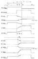
図2は図1の装置における各部の信号(データ)のタイミング関係を示すタイミング図である。図2において、(e1),(e2),(c1),(c2),(e3),(e4),(e5)は回路ゲインが相対的に低くノイズレベルが相対的に低い場合のデータが示され、(E1),(E2),(C1),(C2),(E3),(E4),(E5)は回路ゲインが相対的に高くノイズレベルが相対的に高い場合のデータが示されている。これらは図1について説明した各部の信号乃至データの符号に対応付けされている。尚、e1とE1、および、e2とE2については、双方の場合を兼ねた概念的表記となっている。
【0026】
図2で矢線によりF1として示された領域が図1の撮像素子10の出力に関する画像(画像データ)であり、図6の撮像視野FVA に対応しており、矢線によりF2として示された領域が図1の撮像素子20の出力に関する画像(画像データ)であり、図6の撮像視野FVB に対応している。領域F1とF2とは、図6,図7(B)の重複部Wに対応する重複部Wまたはこれより狭い重複部W′を持つ。
【0027】
図2に示されたように、一の画像F1に属する一の走査ラインe1(E1)およびこの走査ラインe1(E1)とつなぎ合わされる他の画像F2に属する他の走査ラインe2(E2)とを接合するに際し、装置の回路ゲインが相対的に小さくノイズレベルが相対的に低いときには、上記重複部分Wを相対的に広くするようなスムージング処理が行われるように、CPU500の上記動作態様変更機能部501が作用し、混合比配分器40から出力される重み付け係数の出力タイミングが調節される。
【0028】
上記重複部分Wに対応する領域では、上記一の画像F1の中央部に近い側程上記一の走査ラインe1を表わす映像信号の重み(c1)が相対的に大きく上記他の画像F2の中央部に近い側程上記他の走査ラインe2を表わす映像信号の重み(c2)が相対的に大きくなるような重み付けで、重み付け加算処理が加算器30で行われ、上記のように相対的に幅の広い重複部分Wを以てつなぎ合わせ部の境界を目立たなくするようなスムージング処理が行われる。
【0029】
図示のように、時間軸上で見ると、画像F1の始端時点がt1 ,同終端時点がt3 、画像F2の始端時点がt2 ,同終端時点がt4 、重複部分Wの始端時点がt2 ,同終端時点がt3 となる。重み付け係数c1はt1 からt2 までの区間では1を維持し、重複部分Wの始端時点t2 から終端時点t3 に到る間に1から0まで漸減し、他方、重み付け係数c2は重複部分Wの始端時点t2 から終端時点t3 に到る間に0から1まで漸増し、t3 からt4 までの区間では1を維持しする。
【0030】
既述のように、一般的には重複部分Wの幅を大きくする程つなぎ合わせ部の境界が目立たなくなるが、図10を用いて説明したように、信号にノイズが重畳している場合には、スムージング処理が施された重複部だけ隣接領域よりもノイズレベルが抑制され、貼り合わせ処理された結果の合成画像中でつなぎ合わせの部分(重複部)が一層目立ってしまうこととなり、折角のスムージング処理による効果が減殺されてしまうことになる。この傾向はスムージング処理を施す重複部の幅が広い程顕著になる。
【0031】
本実施の形態では、画像信号(映像信号)に重畳したノイズレベルの程度に応じて、ノイズレベルが相対的に低いときには上記重複部分の幅を相対的に広い図示のWとし、ノイズレベルが相対的に高いときには上記重複部分の幅を相対的に狭い図示のW′としてスムージング処理を施すことにより境界部分が目立ってしまうといった問題を解消している。
【0032】
尚、本実施の形態では、CPU500からの指令により、増幅機能部を含む公知のアナログ信号処理部11および21中での増幅率(ゲイン)が低く設定されているときには、ノイズレベルが相対的に低いため、CPU500の動作態様変更機能部501から混合比配分器40に指令を与えて上記スムージング処理を施す重複部分の幅を相対的に広い図示のWとし、同増幅率(ゲイン)が高く設定されているときには、ノイズレベルが相対的に高いため、CPU500の動作態様変更機能部501から混合比配分器40に指令を与えて上記スムージング処理を施す重複部分の幅を相対的に狭い図示のW′とする制御を行っている。
【0033】
図1及び図2により説明した実施の形態とブロック図上での構成を同じくする変形例として、回路ゲイン(ノイズレベル)に応じて上記スムージング処理を施す重複部分の幅を調節するに替えて、信号レベルに応じて上記スムージング処理を施す重複部分の幅を調節する形態を採ることもできる。
即ち、映像信号のガンマー特性等に対応して信号レベルの低い領域ではノイズレベルが相対的に大きくなるため、上記スムージング処理を施す重複部分の幅を相対的に狭くし、信号レベルが十分に高いときにはノイズレベルが相対的に小さくなるため、上記スムージング処理を施す重複部分の幅を相対的に広くして、境界部分を目立たなくする効果が十分られるようにすることができる。
【0034】
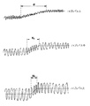
図3は図1および図2を用いて説明した実施の形態、または、上述した変形例の作用を説明するための信号波形図である。いずれも図1における出力信号(データ)E5を表わしたものであり、同図の上段がノイズレベルが相対的に最も低いとき、下段がノイズレベルが相対的に最も高いとき、中段が両者の中間的状態のときを示している。図中、W1 ,W2 ,W3 はそれぞれの場合におけるスムージング処理を施す重複部分の幅を表している。
【0035】
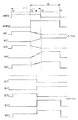
本発明の他の実施の形態として、ブロック図上での構成は図1の実施の形態と同様であり、CPU500の動作態様変更機能部501を異にする形態も可能である。図4はこのような他の実施の形態における作用を表わす各部の信号(データ)のタイミング関係を示すタイミング図である。図4においても、図2同様に、(e1),(e2),(c1),(c2),(e3),(e4),(e5)は回路ゲインが相対的に低くノイズレベルが相対的に低い場合のデータが示されている。これらは図1について説明した各部の信号乃至データの符号に対応付けされている。また(E1′),(E2′),(C1′),(C2′),(E3′),(E4′),(E5′)は回路ゲインが相対的に高くノイズレベルが相対的に高い場合のデータが示されている。尚、e1とE1′、および、e2とE2′については、双方の場合を兼ねた概念的表記となっている。
【0036】
図4の(c1),(c2)と(C1′),(C2′)を比較して理解される通り、この実施の形態では、回路ゲインが相対的に低くノイズレベルが相対的に低い場合には既述の形態同様にスムージング処理が実行されるが、回路ゲインが相対的に高くノイズレベルが相対的に高い場合にはスムージング処理動作が実行されない。従って、ノイズレベルが相対的に高い場合に生じる、スムージング処理を施す重複部分のみでノイズが隣接領域よりも抑制されてかえってこの部分が目立ってしまうといった問題が解消する。上記のようなスムージング処理動作の実行/非実行の切り換え選択はCPU500の動作態様変更機能部501からの指令に基づいて行われる。
【0037】
図4を用いて説明した実施の形態の変形例として、ノイズレベルが相対的に高いか否か(回路ゲインが相対的に高いか否か)に基づいてスムージング処理動作の実行/非実行の切り換え選択を行なうに替えて、映像信号(データ)のレベルが相対的に高いか低いかに応じてスムージング処理動作の実行/非実行の切り換え選択を行なう形態も可能である。
【0038】
図5は図4を用いて説明した実施の形態の変形例の作用を説明するための信号波形図である。図5の(A)は映像信号のレベルが相対的に高い(ノイズレベルが相対的に低い)場合にスムージング処理を行わずに画像を合成した場合を示すものであり、つなぎ合わせの境界部分に映像信号(データ)レベルの段差が顕著に生じて境界が目立っており、つなぎ合わせ不良の場合である。その下の図5(B)は映像信号のレベルが(A)同様の状態にあるときスムージング処理を行うことでつなぎ合わせの境界部分で映像信号(データ)レベルの段差が目立たなくなっており、つなぎ合わせ良好な場合である。
【0039】
図5の(C)は映像信号のレベルが相対的に低い(ノイズレベルが相対的に高い)場合にスムージング処理を行わずに画像を合成した場合を示すものであり、つなぎ合わせの境界部分のノイズレベルが他部と略々同レベルとなって境界が目立ち難く、つなぎ合わせ良好な場合である。その下の図5(D)は映像信号のレベルが(C)同様の状態にあるときスムージング処理を行うことでつなぎ合わせの境界部分でノイズレベルが他部より一段と低くなり、境界が目立っており、つなぎ合わせ不良の場合である。
【0040】
以上図5を用いて説明した形態では映像信号のガンマー特性部の信号レベルが低い領域などに対して同図(C)のうよな処理を施し、映像信号レベルが高い領域に対して同図(B)のような処理を施すようにすることにより、良好な特性を得ることができる。このようなスムージング処理形態の選択は、CPU500の動作態様変更機能部501からの指令に基づいて行われる。
【0041】
以下に、本願に含まれる種々の局面で見た発明を列挙して、それらの作用効果について併記する。
【0042】
(1)複数枚の画像を、各走査ライン毎に、重複部分を持たせてつなぎ合わせることにより合成する操作に相応した画像データ処理を行なう画像処理装置であって、
一の画像に属する一の走査ラインとこの走査ラインとつなぎ合わされる他の画像に属する他の走査ラインとを、上記重複部分に対応する領域では、上記一の画像の中央部に近い側程上記一の走査ラインを表わす映像信号の重みが相対的に大きく上記他の画像の中央部に近い側程上記他の走査ラインを表わす映像信号の重みが相対的に大きくなるような重み付けによる重み付け加算処理を施してつなぎ合わせ部の境界を目立たなくするように構成されたスムージング手段と、
上記映像信号に関するノイズレベルが相対的に低いときには上記重複部分の幅を相対的に広くし、ノイズレベルが相対的に高いときには上記重複部分の幅を相対的に狭くして、上記スムージング手段による重み付け加算処理を行なう対象となる上記重複部分に対応する領域の幅を変更する動作態様変更手段と、
を備えたことを特徴とする画像処理装置。
【0043】
上記(1)の発明以前の技術では、ノイズを含む複数の画像を貼り合わせ(つなぎ合わせ)して一つの画像(画像信号)を作るに際して、貼り合わせの重複部にスムージング処理を施してもつなぎ合わせの部分(重複部)が一層目立ってしまうような不具合があったが、この(1)の発明によればこのような不具合を解消することができる。
【0044】
(2)回路ゲインが相対的に高いときはノイズレベルが相対的に高いと判断することを特徴とする上記(1)に記載の画像処理装置。
【0045】
上記(2)の発明によれば、上記(1)の発明による効果に加えて、特に、回路ゲインが相対的に高いときはノイズレベルが相対的に高いと判断し、適応的にスムージング処理を施してつなぎ合わせの部分(重複部)を目立たなくすることができる。
【0046】
(3)映像信号レベルが相対的に高いときはノイズレベルが相対的に低いと判断することを特徴とする上記(1)に記載の画像処理装置。
【0047】
上記(3)の発明によれば、上記(1)の発明による効果に加えて特に、映像信号レベルが相対的に高いときはノイズレベルが相対的に低いと判断し、適応的にスムージング処理を施してつなぎ合わせの部分(重複部)を目立たなくすることができる。
【0048】
(4)上記動作態様変更手段は、上記映像信号に関する状態としてのノイズレベルまたは回路ゲインに応じて上記スムージング手段による重み付け加算処理の実行または非実行を選択的に変更するように構成されてなるものであることを特徴とする上記(1)に記載の画像処理装置。
【0049】
上記(4)の発明によれば、上記(1)の発明による効果に加えて特に、映像信号に関する状態としてのノイズレベルまたは回路ゲインに応じて適応的にスムージング処理を施してつなぎ合わせの部分(重複部)を目立たなくすることができる。
【0050】
(5)上記動作態様変更手段は、上記映像信号に関する状態としての映像信号レベルに応じて上記スムージング手段による重み付け加算処理の実行または非実行を選択的に変更するように構成されてなるものであることを特徴とする上記(1)に記載の画像処理装置。
【0051】
上記(5)の発明によれば、上記(1)の発明による効果に加えて特に、映像信号レベル(従ってノイズの影響度)に対して適応的にスムージング処理を施してつなぎ合わせの部分(重複部)を目立たなくすることができる。
【0052】
【発明の効果】
本願発明によれば、ノイズを含む複数の画像を貼り合わせ(つなぎ合わせ)して一つの画像(画像信号)を作るに際して、貼り合わせの重複部にスムージング処理を施してもつなぎ合わせの部分(重複部)が目立たないようにし得る画像処理装置を提供することができる。
【図面の簡単な説明】
【図1】本発明の第1の実施の形態としての画像処理装置を示すブロック図である。
【図2】図1の装置における各部の信号(データ)のタイミング関係を示すタイミング図である。
【図3】図1および図2を用いて説明した実施の形態、または、その変形例の作用を説明するための信号波形図である。
【図4】他の実施の形態における作用を表わす各部の信号(データ)のタイミング関係を示すタイミング図である。
【図5】図4を用いて説明した実施の形態の変形例の作用を説明するために用いる信号波形図である。
【図6】貼り合わせ処理の対象とされる複数の画像を複数の撮像素子により生成する様子を示す概念図である。
【図7】図6に示されたような撮像方法により生成された2枚の画像を貼り合わせ処理して得た1枚の連続した画像の状態を示す模式図である。
【図8】従来の装置の構成を示すブロック図である。
【図9】図8の装置における各部の信号(データ)のタイミング関係を示すタイミング図である。
【図10】図8および図9を用いて説明した装置における上述のスムージング処理の特性を示す図である。
【符号の説明】
10 撮像素子
11 アナログ信号処理部
12 A/D変換器
13 メモリ
14 乗算器
20 撮像素子
21 アナログ信号処理部
22 A/D変換器
23 メモリ
24 乗算器
30 加算器
40 混合比配分器
50 CPU
500 CPU
501 動作態様変更機能部[0001]
BACKGROUND OF THE INVENTION
The present invention relates to an image processing apparatus that performs image data processing corresponding to an operation of combining a plurality of images by overlapping (joining) them together with overlapping portions. The present invention is effective when applied to obtain a high-definition image based on an image having the number of pixels.
[0002]
[Prior art]
FIG. 6 is a conceptual diagram showing a state in which a plurality of images to be subjected to the bonding process are generated by a plurality of imaging elements. In FIG. 6, the imaging field of view FVA through the optical system LA of the imaging device SA and the imaging field of view FVB through the optical system LB of the imaging device SB are adjacent to each other with an overlapping portion W. Images (image data) and the like corresponding to the imaging fields of view FVA and FVB are examples of images to be subjected to a pasting (joining) process in this type of image processing apparatus.
[0003]
FIG. 7 is a schematic diagram showing a state of one continuous image obtained by pasting two images generated by the imaging method as shown in FIG.
FIG. 7A shows the state of an image obtained by simply pasting the images corresponding to the imaging fields of view FVA and FVB. In the case of (A), when both the images are pasted together, the geometrical characteristics and gradation characteristics of the images are aligned and joined together with a linear boundary. There is a problem that the boundary line of the joint portion becomes conspicuous as shown in the figure due to the difference in the signal (data) representing the image, that is, the video signal level, due to the sensitivity difference between the two image pickup devices SA and SB.
[0004]
In order to alleviate the problem that the boundary line is conspicuous as in the case of (A), the part (B) in FIG. It is a schematic diagram which shows the image obtained by giving (smoothing).
A method for obtaining an image such as (B) is disclosed in, for example, Japanese Patent Application Laid-Open No. 57-9168.
[0005]
FIG. 8 is a block diagram showing the configuration of a conventional apparatus. The apparatus shown in FIG. 8 has substantially the same configuration as the apparatus disclosed in the above publication. An
[0006]
The output image data read from the first and
[0007]
These image data (C) and (D) are images of respective areas corresponding to the imaging fields of view FVA and FVB of FIG.
[0008]
The
[0009]
The output image data of the
[0010]
FIG. 9 is a timing chart showing the timing relationship of signals (data) of each part in the apparatus of FIG. 9, (A) to (E) are respectively associated with the signals or data (A) to (E) of the respective units described with reference to FIG. The region indicated by F1 in FIG. 9 is an image (image data) relating to the output of the
[0011]
As shown in FIG. 9, one scanning line (C) belonging to one image F1 and another scanning line (D) belonging to another image F2 joined to the scanning line (C) are joined. In the region corresponding to the overlapping portion W, the weight of the video signal representing the one scanning line (C) (that is, the weighting coefficient A) is relatively large toward the side closer to the center of the one image F1. The
[0012]
As shown in the figure, when viewed on the time axis, the start point of the image F1 is t1, the end point is t3, the start point of the image F2 is t2, the end point is t4, and the start point of the overlapping portion W is t2. The end point is t3. The weighting coefficient (A) maintains 1 in the interval from t1 to t2, and gradually decreases from 1 to 0 during the period from the start end time t2 to the end time t3 of the overlapping portion W, while the weighting coefficient (B) overlaps. It gradually increases from 0 to 1 during the period from the start point t2 to the end point t3 of the portion W, and maintains 1 in the section from t3 to t4.
Generally, as the width of the overlapping portion W is increased, the boundary of the joining portion becomes inconspicuous.
[0013]
[Problems to be solved by the invention]
FIG. 10 is a diagram illustrating the characteristics of the smoothing process described above in the apparatus described with reference to FIGS. 8 and 9.
Part (A) of FIG. 10 shows a state in which the image F1 having a relatively low level of the image signal and the image F2 having a relatively high level are joined. Part (B) shows the transition of the image signal level when the smoothing process is applied to the overlapping part and connected. Part (C) shows the characteristics when noise is superimposed on the image signal. As shown in the part (C), in the overlapping part W subjected to the smoothing process, the noise level is suppressed by this process when viewed relative to the other part. As shown in part (D), in the overlapping part W, the noise may be improved by about 3 dB.
In this way, if the noise level is suppressed only in the overlapped portion subjected to the smoothing process, the stitched portion (overlapped portion) becomes more noticeable in the composite image resulting from the pasting process, and the corner smoothing process is performed. The effect of will be reduced.
[0014]
The present invention has been made in view of the circumstances as described above, and when a plurality of images including noise are bonded (joined) to create one image (image signal), smoothing is performed at the overlapping portion of the bonding. It is an object of the present invention to provide an apparatus of this type in which the joined portions (overlapping portions) are not more noticeable by processing.
[0015]
[Means and Actions for Solving the Problems]
In order to solve the above problems, one invention of the present application is:
An image processing apparatus that performs image data processing corresponding to an operation of combining a plurality of images by combining each scan line with overlapping portions,
One scan line belonging to one image and another scan line belonging to another image joined to the scan line are closer to the center of the one image in the region corresponding to the overlapping portion. Weighted addition processing by weighting so that the weight of the video signal representing one scanning line is relatively large and the weight of the video signal representing the other scanning line is relatively large toward the side closer to the center of the other image Smoothing means configured to make the boundary of the joining portion inconspicuous,
When the noise level related to the video signal is relatively low, the width of the overlapping portion is relatively widened, and when the noise level is relatively high, the width of the overlapping portion is relatively narrowed, and weighting by the smoothing means An operation mode changing means for changing the width of the region corresponding to the overlapping portion to be subjected to addition processing ;
An image processing apparatus comprising: ...... (1)
[0016]
Another invention of the present application is:
The image processing apparatus according to (1), wherein when the circuit gain is relatively high, the noise level is determined to be relatively high . ... (2)
[0017]
Yet another invention of the present application is:
The image processing apparatus according to (1), wherein when the video signal level is relatively high, it is determined that the noise level is relatively low . ...... (3)
[0018]
The features seen in various limited aspects of the present invention will be listed below.
The operation mode changing unit is configured to selectively change execution or non-execution of the weighted addition processing by the smoothing unit according to a noise level or a circuit gain as a state relating to the video signal. The image processing apparatus according to (1) above, characterized in that ... (4)
The operation mode changing means is configured to selectively change execution or non-execution of the weighted addition processing by the smoothing means according to the video signal level as a state relating to the video signal. The image processing apparatus described in (1) above, which is characterized ... (5)
[0019]
Embodiment
FIG. 1 is a block diagram showing an image processing apparatus as a first embodiment of the present invention. The embodiment shown in FIG. 1 has substantially the same configuration on the block diagram as the apparatus described with reference to FIG. 8, but an operation mode changing function that performs an operation mode changing function described later in place of the
[0020]
In FIG. 1, an
[0021]
Image data e1 (E1) corresponding to the output of the
[0022]
The image data e1 (E1) and e2 (E2), and thus the image data e3 (E3) and e4 (E4), are in the region corresponding to the imaging fields FVA and FVB in FIG. It is an image. Note that the symbols representing the above data indicated by lower case letters and numbers indicate data when the noise level is relatively low, and those indicated by the upper case letters and numbers in parentheses are relative to the noise level. This is a convenient notation showing data in the case of high, and so on.
[0023]
The
[0024]
The output image data of the
[0025]
FIG. 2 is a timing chart showing the timing relationship of signals (data) of each part in the apparatus of FIG. In FIG. 2, (e1), (e2), (c1), (c2), (e3), (e4), and (e5) are data when the circuit gain is relatively low and the noise level is relatively low. (E1), (E2), (C1), (C2), (E3), (E4), and (E5) show data when the circuit gain is relatively high and the noise level is relatively high. Has been. These are associated with the codes of the signals or data of each part described with reference to FIG. Note that e1 and E1 and e2 and E2 are conceptual notations that serve both cases.
[0026]
The area indicated by F1 in FIG. 2 as an arrow F1 is an image (image data) relating to the output of the
[0027]
As shown in FIG. 2, one scan line e1 (E1) belonging to one image F1 and another scan line e2 (E2) belonging to another image F2 joined to the scan line e1 (E1) When the circuit gain of the apparatus is relatively small and the noise level is relatively low, the operation mode changing function of the
[0028]
In the region corresponding to the overlapping portion W, the weight (c1) of the video signal representing the one scanning line e1 is relatively larger toward the side closer to the central portion of the one image F1, and the central portion of the other image F2. The weighting and adding process is performed by the
[0029]
As shown in the figure, when viewed on the time axis, the start point of the image F1 is t1, the end point is t3, the start point of the image F2 is t2, the end point is t4, and the start point of the overlapping portion W is t2. The end point is t3. The weighting coefficient c1 maintains 1 in the interval from t1 to t2, and gradually decreases from 1 to 0 during the period from the start end point t2 to the end point t3 of the overlapped portion W, while the weighting coefficient c2 is the start end of the overlapped portion W. It gradually increases from 0 to 1 during the period from the time point t2 to the end time point t3, and maintains 1 in the interval from t3 to t4.
[0030]
As described above, in general, the boundary of the joining portion becomes inconspicuous as the width of the overlapping portion W is increased. However, as described with reference to FIG. 10, when noise is superimposed on the signal, The noise level is suppressed only in the overlapped areas where the smoothing process has been performed, compared to the adjacent area, and the stitched parts (overlapped areas) become more noticeable in the resultant composite image. The effect of processing will be diminished. This tendency becomes more prominent as the width of the overlapping portion subjected to the smoothing process is wider.
[0031]
In the present embodiment, according to the level of the noise level superimposed on the image signal (video signal), when the noise level is relatively low, the width of the overlapped portion is set to a relatively wide W, and the noise level is relative. On the other hand, the problem that the boundary portion becomes conspicuous can be solved by performing the smoothing process when the width of the overlapping portion is relatively narrow as shown in FIG.
[0032]
In the present embodiment, when the amplification factor (gain) in the known analog
[0033]
As a modified example having the same configuration on the block diagram as the embodiment described with reference to FIGS. 1 and 2, instead of adjusting the width of the overlapping portion to be subjected to the smoothing process according to the circuit gain (noise level), It is also possible to take a form in which the width of the overlapped portion to be subjected to the smoothing process is adjusted according to the signal level.
That is, since the noise level is relatively large in the low signal level region corresponding to the gamma characteristics of the video signal, the width of the overlapping portion where the smoothing process is performed is relatively narrow, and the signal level is sufficiently high. Since the noise level is sometimes relatively small, the width of the overlapping portion subjected to the smoothing process can be made relatively wide so that the effect of making the boundary portion inconspicuous is sufficient.
[0034]
FIG. 3 is a signal waveform diagram for explaining the operation of the embodiment described with reference to FIGS. 1 and 2 or the modification described above. Each represents the output signal (data) E5 in FIG. 1. When the noise level is relatively lowest in the upper part of the figure, the noise level is relatively highest in the lower part, and the middle part is between the two. It shows the time of the target state. In the figure, W1, W2, and W3 represent the widths of the overlapping portions to be smoothed in each case.
[0035]
As another embodiment of the present invention, the configuration on the block diagram is the same as that of the embodiment of FIG. 1, and the operation mode changing
[0036]
As can be understood by comparing (c1), (c2) and (C1 ′), (C2 ′) in FIG. 4, in this embodiment, the circuit gain is relatively low and the noise level is relatively low. As in the above-described embodiment, the smoothing process is executed. However, when the circuit gain is relatively high and the noise level is relatively high, the smoothing process operation is not executed. Therefore, the problem that the noise is suppressed more than the adjacent region only in the overlapping portion where the smoothing process is performed, which occurs when the noise level is relatively high, is solved. The selection of execution / non-execution of the smoothing processing operation as described above is performed based on a command from the operation mode
[0037]
As a modification of the embodiment described with reference to FIG. 4, switching between execution / non-execution of the smoothing processing operation based on whether or not the noise level is relatively high (whether or not the circuit gain is relatively high). Instead of performing the selection, a mode is also possible in which the smoothing operation is switched between execution and non-execution according to whether the level of the video signal (data) is relatively high or low.
[0038]
FIG. 5 is a signal waveform diagram for explaining the operation of the modification of the embodiment described with reference to FIG. FIG. 5A shows a case where an image is synthesized without performing smoothing processing when the level of the video signal is relatively high (noise level is relatively low). This is a case where the level difference of the video signal (data) level is noticeable and the boundary is conspicuous, resulting in poor jointing. In FIG. 5B below, when the level of the video signal is in the same state as in (A), the step of the video signal (data) level becomes inconspicuous at the boundary portion of the stitching by performing the smoothing process. This is a good case.
[0039]
FIG. 5C shows a case where an image is synthesized without performing smoothing processing when the level of the video signal is relatively low (the noise level is relatively high). This is a case where the noise level is substantially the same as the other parts, the boundary is not conspicuous, and the connection is good. In FIG. 5D below, when the level of the video signal is in the same state as in FIG. 5C, the smoothing process is performed, so that the noise level becomes lower than the other part at the boundary part of the joint, and the boundary is conspicuous. This is a case of poor jointing.
[0040]
In the embodiment described above with reference to FIG. 5, the processing as shown in FIG. 5C is performed on a region where the signal level of the gamma characteristic portion of the video signal is low, and the region where the video signal level is high is shown in FIG. By performing the treatment as in (B), good characteristics can be obtained. Such selection of the smoothing processing mode is performed based on a command from the operation mode changing
[0041]
Below, the invention seen in the various situation contained in this application is enumerated, and those effects are described together.
[0042]
(1) An image processing apparatus that performs image data processing corresponding to an operation of combining a plurality of images by combining each scan line with overlapping portions.
One scan line belonging to one image and another scan line belonging to another image joined to the scan line are closer to the center of the one image in the region corresponding to the overlapping portion. Weighted addition processing by weighting so that the weight of the video signal representing one scanning line is relatively large and the weight of the video signal representing the other scanning line is relatively large toward the side closer to the center of the other image Smoothing means configured to make the boundary of the joining portion inconspicuous,
When the noise level related to the video signal is relatively low, the width of the overlapping portion is relatively widened, and when the noise level is relatively high, the width of the overlapping portion is relatively narrowed, and weighting by the smoothing means An operation mode changing means for changing the width of the region corresponding to the overlapping portion to be subjected to addition processing ;
An image processing apparatus comprising:
[0043]
In the technology before the invention of (1), when a plurality of images including noise are pasted (joined) to create one image (image signal), the overlapping portion of the pasting is subjected to a smoothing process to connect There is a problem that the combined part (overlapping part) becomes more conspicuous. According to the invention of (1), such a problem can be solved.
[0044]
(2) The image processing apparatus according to (1), wherein when the circuit gain is relatively high, it is determined that the noise level is relatively high .
[0045]
According to the invention of (2) above, in addition to the effect of the invention of (1) above, particularly when the circuit gain is relatively high, it is determined that the noise level is relatively high, and the smoothing process is adaptively performed. It is possible to make the joining portion (overlapping portion) inconspicuous.
[0046]
(3) The image processing apparatus according to (1), wherein when the video signal level is relatively high, it is determined that the noise level is relatively low .
[0047]
According to the invention of (3) above, in addition to the effect of the invention of (1) above, particularly when the video signal level is relatively high, it is determined that the noise level is relatively low, and the smoothing process is adaptively performed. It is possible to make the joining portion (overlapping portion) inconspicuous.
[0048]
(4) The operation mode changing unit is configured to selectively change execution or non-execution of the weighted addition processing by the smoothing unit according to a noise level or a circuit gain as a state relating to the video signal. The image processing apparatus according to (1), wherein:
[0049]
According to the invention of (4) above, in addition to the effects of the invention of (1) above, in particular, a smoothing process is applied adaptively according to the noise level or circuit gain as the state relating to the video signal, (Overlapping part) can be made inconspicuous.
[0050]
(5) The operation mode changing means is configured to selectively change execution or non-execution of the weighted addition processing by the smoothing means in accordance with a video signal level as a state relating to the video signal. The image processing apparatus according to (1), characterized in that:
[0051]
According to the invention of the above (5), in addition to the effect of the invention of the above (1), in particular, a smoothing process is applied adaptively to the video signal level (and hence the influence of noise), and the stitched part (overlapping) Part) can be made inconspicuous.
[0052]
【The invention's effect】
According to the present invention, when a plurality of images including noise are joined (joined) to create one image (image signal), a smoothing process is performed on the overlapped part of the joined parts (overlapping part). It is possible to provide an image processing apparatus that can prevent the image from being conspicuous.
[Brief description of the drawings]
FIG. 1 is a block diagram showing an image processing apparatus as a first embodiment of the present invention.
FIG. 2 is a timing chart showing a timing relationship of signals (data) of respective units in the apparatus of FIG.
FIG. 3 is a signal waveform diagram for explaining the operation of the embodiment described with reference to FIGS. 1 and 2 or a modification thereof;
FIG. 4 is a timing diagram showing a timing relationship of signals (data) of respective parts representing the operation in another embodiment.
FIG. 5 is a signal waveform diagram used for explaining the operation of the modification of the embodiment described with reference to FIG. 4;
FIG. 6 is a conceptual diagram illustrating a state in which a plurality of images to be subjected to a bonding process are generated by a plurality of imaging elements.
7 is a schematic diagram showing a state of one continuous image obtained by pasting two images generated by the imaging method as shown in FIG. 6; FIG.
FIG. 8 is a block diagram showing a configuration of a conventional apparatus.
9 is a timing chart showing a timing relationship of signals (data) of respective units in the apparatus of FIG.
10 is a diagram illustrating the characteristics of the smoothing process described above in the apparatus described with reference to FIGS. 8 and 9. FIG.
[Explanation of symbols]
DESCRIPTION OF
500 CPU
501 Operation mode change function unit
Claims (3)
一の画像に属する一の走査ラインとこの走査ラインとつなぎ合わされる他の画像に属する他の走査ラインとを、上記重複部分に対応する領域では、上記一の画像の中央部に近い側程上記一の走査ラインを表わす映像信号の重みが相対的に大きく上記他の画像の中央部に近い側程上記他の走査ラインを表わす映像信号の重みが相対的に大きくなるような重み付けによる重み付け加算処理を施してつなぎ合わせ部の境界を目立たなくするように構成されたスムージング手段と、
上記映像信号に関するノイズレベルが相対的に低いときには上記重複部分の幅を相対的に広くし、ノイズレベルが相対的に高いときには上記重複部分の幅を相対的に狭くして、上記スムージング手段による重み付け加算処理を行なう対象となる上記重複部分に対応する領域の幅を変更する動作態様変更手段と、
を備えたことを特徴とする画像処理装置。An image processing apparatus that performs image data processing corresponding to an operation of combining a plurality of images by combining each scan line with overlapping portions,
One scan line belonging to one image and another scan line belonging to another image joined to the scan line are closer to the center of the one image in the region corresponding to the overlapping portion. Weighted addition processing by weighting so that the weight of the video signal representing one scanning line is relatively large and the weight of the video signal representing the other scanning line is relatively large toward the side closer to the center of the other image Smoothing means configured to make the boundary of the joining portion inconspicuous,
When the noise level related to the video signal is relatively low, the width of the overlapping portion is relatively widened, and when the noise level is relatively high, the width of the overlapping portion is relatively narrowed, and weighting by the smoothing means An operation mode changing means for changing the width of the region corresponding to the overlapping portion to be subjected to addition processing ;
An image processing apparatus comprising:
Priority Applications (1)
| Application Number | Priority Date | Filing Date | Title |
|---|---|---|---|
| JP17989696A JP3662075B2 (en) | 1996-06-19 | 1996-06-19 | Image processing device |
Applications Claiming Priority (1)
| Application Number | Priority Date | Filing Date | Title |
|---|---|---|---|
| JP17989696A JP3662075B2 (en) | 1996-06-19 | 1996-06-19 | Image processing device |
Publications (2)
| Publication Number | Publication Date |
|---|---|
| JPH1013769A JPH1013769A (en) | 1998-01-16 |
| JP3662075B2 true JP3662075B2 (en) | 2005-06-22 |
Family
ID=16073805
Family Applications (1)
| Application Number | Title | Priority Date | Filing Date |
|---|---|---|---|
| JP17989696A Expired - Fee Related JP3662075B2 (en) | 1996-06-19 | 1996-06-19 | Image processing device |
Country Status (1)
| Country | Link |
|---|---|
| JP (1) | JP3662075B2 (en) |
Families Citing this family (1)
| Publication number | Priority date | Publication date | Assignee | Title |
|---|---|---|---|---|
| JP4876803B2 (en) * | 2006-09-08 | 2012-02-15 | 大日本印刷株式会社 | Inspection image acquisition method |
-
1996
- 1996-06-19 JP JP17989696A patent/JP3662075B2/en not_active Expired - Fee Related
Also Published As
| Publication number | Publication date |
|---|---|
| JPH1013769A (en) | 1998-01-16 |
Similar Documents
| Publication | Publication Date | Title |
|---|---|---|
| JP2951909B2 (en) | Gradation correction device and gradation correction method for imaging device | |
| US5521636A (en) | Horizontal line interpolation circuit and image pickup apparatus including it | |
| US7148925B2 (en) | Solid-state honeycomb type image pickup apparatus using a complementary color filter and signal processing method therefor | |
| JPS6359266A (en) | Method and apparatus for regulating picture contrast | |
| US7728882B2 (en) | Green reconstruction for image sensors | |
| JPH07298275A (en) | Signal processing circuit for video camera | |
| US5784499A (en) | Method for reducing noise in image signals and apparatus therefor | |
| JP4119290B2 (en) | Video processing apparatus and imaging system | |
| JPH055432B2 (en) | ||
| JP3662075B2 (en) | Image processing device | |
| US6380973B1 (en) | Image sensing apparatus and method for image processing a moving image or a still image | |
| JP3410008B2 (en) | Contour compensation system | |
| JP3725609B2 (en) | Image input device | |
| JP3578246B2 (en) | Solid-state imaging device | |
| JPH1023331A (en) | Image processor | |
| JP2698404B2 (en) | Luminance signal processing device | |
| JPH0221200B2 (en) | ||
| JP3196423B2 (en) | High chroma image detail compensation circuit | |
| JP4626104B2 (en) | Video signal processing circuit | |
| JP3739066B2 (en) | Television camera device | |
| JP3962518B2 (en) | Image signal processing device | |
| JP2698406B2 (en) | Imaging device | |
| JP2551113B2 (en) | Noise reduction device | |
| JP2890774B2 (en) | Image enlargement device and imaging device with electronic zoom function | |
| JPH09130816A (en) | Signal processing circuit |
Legal Events
| Date | Code | Title | Description |
|---|---|---|---|
| A977 | Report on retrieval |
Free format text: JAPANESE INTERMEDIATE CODE: A971007 Effective date: 20041221 |
|
| A131 | Notification of reasons for refusal |
Free format text: JAPANESE INTERMEDIATE CODE: A131 Effective date: 20041228 |
|
| A521 | Request for written amendment filed |
Free format text: JAPANESE INTERMEDIATE CODE: A523 Effective date: 20050228 |
|
| TRDD | Decision of grant or rejection written | ||
| A01 | Written decision to grant a patent or to grant a registration (utility model) |
Free format text: JAPANESE INTERMEDIATE CODE: A01 Effective date: 20050318 |
|
| A61 | First payment of annual fees (during grant procedure) |
Free format text: JAPANESE INTERMEDIATE CODE: A61 Effective date: 20050322 |
|
| FPAY | Renewal fee payment (event date is renewal date of database) |
Free format text: PAYMENT UNTIL: 20090401 Year of fee payment: 4 |
|
| FPAY | Renewal fee payment (event date is renewal date of database) |
Free format text: PAYMENT UNTIL: 20090401 Year of fee payment: 4 |
|
| FPAY | Renewal fee payment (event date is renewal date of database) |
Free format text: PAYMENT UNTIL: 20100401 Year of fee payment: 5 |
|
| FPAY | Renewal fee payment (event date is renewal date of database) |
Free format text: PAYMENT UNTIL: 20110401 Year of fee payment: 6 |
|
| FPAY | Renewal fee payment (event date is renewal date of database) |
Free format text: PAYMENT UNTIL: 20120401 Year of fee payment: 7 |
|
| FPAY | Renewal fee payment (event date is renewal date of database) |
Free format text: PAYMENT UNTIL: 20130401 Year of fee payment: 8 |
|
| FPAY | Renewal fee payment (event date is renewal date of database) |
Free format text: PAYMENT UNTIL: 20140401 Year of fee payment: 9 |
|
| LAPS | Cancellation because of no payment of annual fees |