JP3676006B2 - Fuel injection pump control device - Google Patents
Fuel injection pump control device Download PDFInfo
- Publication number
- JP3676006B2 JP3676006B2 JP33635596A JP33635596A JP3676006B2 JP 3676006 B2 JP3676006 B2 JP 3676006B2 JP 33635596 A JP33635596 A JP 33635596A JP 33635596 A JP33635596 A JP 33635596A JP 3676006 B2 JP3676006 B2 JP 3676006B2
- Authority
- JP
- Japan
- Prior art keywords
- fuel
- governor
- fuel injection
- injection amount
- piston
- Prior art date
- Legal status (The legal status is an assumption and is not a legal conclusion. Google has not performed a legal analysis and makes no representation as to the accuracy of the status listed.)
- Expired - Lifetime
Links
- 239000000446 fuel Substances 0.000 title claims description 90
- 238000002347 injection Methods 0.000 title claims description 85
- 239000007924 injection Substances 0.000 title claims description 85
- 239000012530 fluid Substances 0.000 claims description 30
- XLYOFNOQVPJJNP-UHFFFAOYSA-N water Substances O XLYOFNOQVPJJNP-UHFFFAOYSA-N 0.000 description 20
- 230000003247 decreasing effect Effects 0.000 description 7
- 238000006073 displacement reaction Methods 0.000 description 6
- 238000010586 diagram Methods 0.000 description 4
- MWUXSHHQAYIFBG-UHFFFAOYSA-N Nitric oxide Chemical compound O=[N] MWUXSHHQAYIFBG-UHFFFAOYSA-N 0.000 description 3
- 230000000903 blocking effect Effects 0.000 description 1
- 238000002485 combustion reaction Methods 0.000 description 1
- 230000006835 compression Effects 0.000 description 1
- 238000007906 compression Methods 0.000 description 1
- 230000036461 convulsion Effects 0.000 description 1
- 230000003111 delayed effect Effects 0.000 description 1
- 230000000694 effects Effects 0.000 description 1
- 239000007789 gas Substances 0.000 description 1
- 238000003780 insertion Methods 0.000 description 1
- 230000037431 insertion Effects 0.000 description 1
- 239000000463 material Substances 0.000 description 1
- 238000000034 method Methods 0.000 description 1
- JLQFVGYYVXALAG-CFEVTAHFSA-N yasmin 28 Chemical compound OC1=CC=C2[C@H]3CC[C@](C)([C@](CC4)(O)C#C)[C@@H]4[C@@H]3CCC2=C1.C([C@]12[C@H]3C[C@H]3[C@H]3[C@H]4[C@@H]([C@]5(CCC(=O)C=C5[C@@H]5C[C@@H]54)C)CC[C@@]31C)CC(=O)O2 JLQFVGYYVXALAG-CFEVTAHFSA-N 0.000 description 1
Images




Classifications
-
- Y—GENERAL TAGGING OF NEW TECHNOLOGICAL DEVELOPMENTS; GENERAL TAGGING OF CROSS-SECTIONAL TECHNOLOGIES SPANNING OVER SEVERAL SECTIONS OF THE IPC; TECHNICAL SUBJECTS COVERED BY FORMER USPC CROSS-REFERENCE ART COLLECTIONS [XRACs] AND DIGESTS
- Y02—TECHNOLOGIES OR APPLICATIONS FOR MITIGATION OR ADAPTATION AGAINST CLIMATE CHANGE
- Y02T—CLIMATE CHANGE MITIGATION TECHNOLOGIES RELATED TO TRANSPORTATION
- Y02T10/00—Road transport of goods or passengers
- Y02T10/10—Internal combustion engine [ICE] based vehicles
- Y02T10/12—Improving ICE efficiencies
Landscapes
- High-Pressure Fuel Injection Pump Control (AREA)
- Output Control And Ontrol Of Special Type Engine (AREA)
Description
【0001】
【発明の属する技術分野】
本発明は内燃機関用燃料噴射ポンプ、特にディーゼルエンジン用ジャーク式燃料噴射ポンプの制御装置に関する。
【0002】
【従来の技術】
図4はディーゼルエンジン用制御装置の一例を示す平面図である。
図4において、100はエンジン本体、1は燃料を加圧して燃料噴射弁(図示せず)に供給する燃料噴射ポンプ、12はエンジンの回転数を制御するガバナ、2は前記燃料噴射ポンプ1の燃料噴射量を調整する燃料ラックである。
【0003】
かかるディーゼルエンジンにおいては、フライウエイトの速心力とガバナスプリングとの力の釣り合いによって変化するシフタを出力端とする機械式ガバナ、エンジン回転数変化により油圧で作動するパワーピストンを出力端とする油圧式ガバナ、そしてエンジン回転数あるいは負荷を入力とし、アナログあるいはデジタル電子制御により作動するアクチュエータを出力端とする電子ガバナ等が使用されているが、これら各ガバナの上記出力端が図4に示すガバナ出力リンク3に連結される。
【0004】
そして、前記ガバナ出力リンク3はこれに固定された連結リンク4を介して前記燃料ラック2に連結される。7は前記ガバナ出力リンク3を往復摺動自在に支持するブラケットで、エンジン本体100にボルトにより固定されている。
【0005】
かかる燃料噴射ポンプ制御装置を備えたディーゼルエンジンの運転時において、エンジン回転数あるいは負荷の増減によってガバナ12からの出力がガバナ出力リンク3に伝達され、これが図4のZ矢印のように往復移動する。この往復変位は連結リンク4を介して燃料ラック2に伝達され、該燃料ラック2が往復動せしめられる。該ラック2の往復変位によって周知のように、燃料噴射ポンプ1のピニオンを介してプランジャが回動されてこれの有効行程が変化せしめられ、これによって燃料噴射量が変化せしめられる。
【0006】
【発明が解決しようとする課題】
前記ディーゼルエンジンにおいては、排気ガス中の窒素酸化物(NOX )の発生を抑制するため、燃料とともに水を噴射する方式が種々提供されている。かかるディーゼルエンジンにおいて、1本の燃料噴射弁より燃料と水とを混合噴射させる方式の場合、燃料に水が添加される分、燃料噴射ポンプ1からの噴射量は燃料のみの噴射に較べて大幅に増加する必要がある。
【0007】
然るに燃料噴射制御を司さどるガバナ12は、一般に燃料のみの噴射量制御を行なう事を前提としてエンジンの最大出力時における燃料制御作動最大範囲を設定している。つまり、かかる従来技術では図5に示す燃料噴射量線図において、ガバナ12の燃料制御最大値即ちガバナの最大作動量M1及びこれに対応する最大燃料噴射量Q1を設定している。
【0008】
このため、かかるディーゼルエンジンにおいては、上記のように水が添加されると、これによる噴射量の増加に対応する量だけ、ガバナ12はその作動範囲即ち最大作動量M1を超えて作動することを要し、これによってガバナ12による噴射量制御が不可能となるという問題が生ずる。
【0009】
本発明はかかる従来技術の課題に鑑み、ガバナの最大作動量即ち作動範囲を変えることなく、水噴射等の他流体の噴射に伴う噴射量増に対応可能として、燃料と水等との二流体噴射及び燃料のみの噴射の切り換えをガバナ性能を変えることなく自在に実施可能とした燃料噴射ポンプの制御装置を提供することを目的とする。
【0010】
【課題を解決するための手段】
本発明はかかる課題を解決するために、ガバナの出力をガバナ出力リンクを介して燃料噴射ポンプの燃料噴射量調整用の燃料ラックに伝達するようにした燃料噴射ポンプ制御装置において、
前記ガバナ出力リンクと燃料ラックとを、該ガバナ出力リンクに往復動可能に挿通された連結リンク及び該連結リンクと前記ガバナ出力リンクとの間に介装されて前記燃料ラックを噴射量減の方向に付勢するばねを介して連結するとともに、前記ガバナ出力リンクに固定されたシリンダと該シリンダ内を往復動するピストンと該ピストンの端部に固定された調整ねじを備えた流体圧シリンダを設け、前記ガバナ出力リンクの燃料増方向への移動を前記シリンダ、ピストン及び調整ねじを介して前記燃料ラックに伝達可能に、かつ該ピストン及び調整ねじが前記ばねを圧縮する方向に変位することにより前記燃料ラックが噴射量増となるように構成し、前記流体圧シリンダへの作動流体供給路には、該流体圧シリンダのピストン及び前記調整ねじを移動せしめるための作動流体の該流体圧シリンダへの供給、遮断を司どる電磁弁を設けてなることを特徴とする燃料噴射ポンプ制御装置を提案する。
【0011】
さらに本発明は、前記手段に加えて、前記ガバナ出力軸と燃料ラックとを連結リンクを介して連結し、該連結リンクの一端面と前記ガバナ出力リンクとの間に前記ばねを介装し、該連結リンクの前記ばねとは逆方向の面に前記調整ねじの端面を当接し、該調整ねじを突出せしめたとき、前記燃料ラックが前記連結リンクを介して噴射量増の方向に移動するように構成する。
【0012】
かかる発明によれば、水(他の流体も含む)噴射に対応する際には電磁弁を閉として、流体圧シリンダの一方側の流体室への流体の供給を遮断することにより、調整ねじを介して燃料ラックを噴射量増量位置にシフトせしめる。即ち、ガバナ出力リンクの位置、つまりガバナ作動量を変更することなく燃料噴射ポンプの噴射量を増加し、水噴射による噴射量増加に対応することができる。
【0013】
水噴射を遮断する際には、電磁弁を閉として流体圧シリンダの双方の流体室に作動流体を供給すると、流体圧シリンダ内の面積差により、調整ねじを介して燃料ラックは噴射量減の方向に引き戻され前記水噴射のための噴射量増のシフトが解除される。
【0014】
従って、流体圧シリンダへの作動流体の給排を電磁弁によって制御することにより、ガバナ作動量を変化させることを要さずに噴射量の増減を行なうことができ、ガバナを最大燃料噴射量に対応する最大作動範囲内で水噴射による噴射量の増量が実現できる。
【0015】
また、流体圧シリンダに取付けられた調整ねじの突出量を調整することにより、噴射量の増化量を任意に調整することができる。
【0016】
【発明の実施の形態】
以下、図面を参照して本発明の好適な実施例を例示的に詳しく説明する。
但し、この実施例に記載されている構成部品の寸法、材質、形状、その相対的配置等は特に特定的な記載がないかぎりは、この発明の範囲をそれに限定する趣旨ではなく、単なる説明例にすぎない。
【0017】
図1は本発明の実施形態に係るディーゼルエンジンの燃料噴射ポンプ制御装置の要部平面図、図2はエアシリンダ取付部近傍の構造図、図3は作用説明図である。
【0018】
図1〜図2において、1は燃料噴射ポンプ、2は該燃料噴射ポンプ1の燃料噴射量を調整する燃料ラック、12は前記機械式ガバナ、油圧式ガバナ、電子ガバナ等を含むガバナである。
【0019】
3は該ガバナ12の出力端であるガバナ出力リンク、7はエンジン本体100に固着されて、該ガバナ出力リンク3を往復摺動自在に支持するブラケットである。
4はボス部4a及びレバー部4bからなる連結リンクであり、該レバー部4bの端部が前記燃料ラック2に固定され、ボス部4aの挿通孔内に前記ガバナ出力リンク3が往復動可能に挿通されている。
【0020】
6は、前記連結リンク4のボス部4aのガバナ12側端面4cと前記ガバナ出力リンク3に形成されたばね受部3aとの間に、架設されたばねで、圧縮ばねにて構成され、前記連結リンク4を介して燃料ラック2を噴射量「0」(ゼロ)の方向(図2のY矢印と逆方向)に付勢している。
従って、前記ガバナ出力リンク3と連結リンク4とは直接に連結されず、ばね6を介して連結させることとなる。
【0021】
5はシリンダ5dが前記ガバナ出力リンク3に固定されたエアシリンダであり、該エアシリンダ5の往復動用ピストン5aの一端には調整ねじ11が取り付けられ、該調整ねじ11の先端が前記連結リンク4のレバー部4bの反ガバナ側の板面4d(前記ボス4aの端面4cとは反対側の板面)に、前記ばね6の弾力により常時、当接されるようになっている。
【0022】
5bは該エアシリンダ5のピストン5aによって区画された第1の空気室、5cは第2の空気室、9は該第2の空気量5cに接続される主空気管、10は第1の空気室5bに接続されるパイロット空気管、8は該パイロット空気管10に設けられた開閉制御用の電磁弁である。前記第1の空気室5bの断面積は、第2の空気室5cよりも大きく形成されている。
【0023】
そして、前記エアシリンダ5の第2の空気室5cには、前記主空気管9を経て、常時所定圧力に加圧された空気が供給され、また第1の空気室5bには、前記パイロット空気管10を経て電磁弁8の開閉により、空気が給断されるようになっている。
【0024】
かかる構成を備えた燃料噴射ポンプの制御装置を用いたディーゼルエンジンの運転時において、前記ガバナ出力リンク3が燃料減の方向に作動すると、該ガバナ出力リンク3から前記ばね6及び前記連結リンク4を介して燃料ラック2が燃料減の方向(図2のY矢と逆方向)に作動せしめられる。また、前記ガバナ出力リンク3が燃料増の方向に作動すると、前記のように該ガバナ出力リンク3に固定されたシリンダ5d及び常時空気圧が作用している第2の空気室5c及びピストン5a及び調整ねじ11を介して前記燃料ラック2が燃料増の方向(図2のY矢方向)に作動せしめられる。
そして、前記パイロット空気管10の電磁弁8を閉じると、エアシリンダ5の第2の空気室5cには主空気管9を経た加圧空気が供給されている状態で、第1の空気室5bへの空気の供給が遮断される。これによりエアシリンダ5のピストン5a及び調整ねじ11は、燃料ラック2を図2の右方向即ちY矢印にて示す噴射量増の方向に、該ピストン5aのストローク相当分だけ変位させる。
【0025】
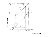
即ち、図3において、ガバナ作動量M2(ガバナ変位量a)にて燃料ラック2がc分だけ噴射量増の方向に変位し、同じガバナ作動量M2にこのcに相当する量だけ水の噴射量を許容することとなる。
【0026】
この状態でガバナ作動量Mが増加すると、燃料ラック2は図3のA線に沿って噴射量が増加するように変位せしめられ、燃料と水の噴射がなされる。
そして、水の噴射が終了し、図3のガバナ変位量bにおいて、電磁弁8が開に切り換えられると、エアシリンダ5の第1の空気室5bにパイロット空気管10を経たパイロット空気(第2の空気室5cの空気と同じ圧力)が供給される。
【0027】
これを受けて、ピストン5aは第1の空気室5bと第2の空気室5cとの断面積差によって図2のY矢印と逆方向即ち噴射量減の方向に調整ねじ11とともに変位し、燃料ラック2は前記ばね6の弾力により連結リンク4を介して、同じガバナ作動量M3の状態で、噴射量減の方向(図3のB点からC点まで)に押し戻される。
これによって図3のC点からD点までは燃料のみの噴射がガバナ12の制御によってなされる。
【0028】
上記水の噴射に対応する燃料ラック2の増化量即ち図3のcの量は、エアシリンダ5のピストン5aに取り付けられた調整ねじ11の突出量を調整することにより、任意に調整することができる。
【0029】
また、水の噴射始め時期における燃料ラック2の噴射量増への変位開始位置即ち図3のa位置及び水の噴射終了時期における燃料ラック2の噴射量減への変位開始位置即ち図3のb位置の調整は、パイロット空気管10の電磁弁8の開始時期及び閉塞時期を変えることより夫々行なうことができる。
【0030】
即ち、電磁弁8の閉時期を早くすれば図3のaが小さくなって、水噴射のための燃料ラック2の噴射量増へのシフトが早くなり、電磁弁8の開時期を早くすれば、図3のb位置が小さくなって水噴射のためのシフトの解除(噴射量減)が早くなる(電磁弁8の開閉時期を遅くするときは上記と逆)。
【0031】
尚、この実施形態におけるエアシリンダ5に代えて油圧シリンダ等、他の流体を使用した流体圧シリンダとすることもできる。
【0032】
【発明の効果】
以上の記載の如く、本発明によれば、燃料噴射ポンプの燃料ラックに調整ねじを介して連結された流体圧シリンダへの作動流体の給排を電磁弁によって制御することにより、ガバナ作動量を変化させることを要さずに噴射量の増減を行なうことができ、ガバナを最大燃料噴射量に対応する最大作動範囲内で水噴射による噴射量の増量が実現する。
【0033】
また、流体圧シリンダに取り付けられた調整ねじの突出量を調整することにより、噴射量の増加量を任意に調整することができる。
これにより、エンジンの停止時、運転時の何れにおいても、燃料のみの運転と燃料、水噴射運転との切り換えがガバナ性能を変えることなく、容易に実現できる。
【図面の簡単な説明】
【図1】本発明の実施形態に係るディーゼルエンジンの燃料噴射ポンプ制御装置の要部平面図である。
【図2】図1の実施形態におけるシリンダ(流体圧シリンダ)取付部近傍の拡大構造図である。
【図3】図1の実施形態における作用説明図ある。
【図4】従来の燃料噴射ポンプ制御装置の要部平面図である。
【図5】図4の従来技術の作用説明図である。
【符号の説明】
1 燃料噴射ポンプ
2 燃料ラック
3 ガバナ出力リンク
4 連結リンク
5 エアシリンダ
5a ピストン
5b 第1の空気室
5c 第2の空気室
6 ばね
8 電磁弁
9 主空気管
10 パイロット空気管
11 調整ねじ
12 ガバナ[0001]
BACKGROUND OF THE INVENTION
The present invention relates to a fuel injection pump for an internal combustion engine, and more particularly to a control device for a jerk fuel injection pump for a diesel engine.
[0002]
[Prior art]
FIG. 4 is a plan view showing an example of a control device for a diesel engine.
In FIG. 4, 100 is an engine body, 1 is a fuel injection pump that pressurizes fuel and supplies it to a fuel injection valve (not shown), 12 is a governor that controls the rotational speed of the engine, and 2 is the fuel injection pump 1. It is a fuel rack that adjusts the fuel injection amount.
[0003]
In such a diesel engine, a mechanical governor whose output end is a shifter that changes depending on the balance between the force of the flyweight and the governor spring, and a hydraulic type whose output end is a power piston that operates hydraulically due to a change in engine speed The governor and an electronic governor having an output that is an actuator that is operated by analog or digital electronic control with the engine speed or load as an input are used. The output ends of these governors are the governor outputs shown in FIG. Connected to link 3.
[0004]
The
[0005]
During operation of a diesel engine equipped with such a fuel injection pump control device, the output from the governor 12 is transmitted to the
[0006]
[Problems to be solved by the invention]
In the diesel engine, various methods for injecting water together with fuel are provided in order to suppress generation of nitrogen oxide (NO x ) in exhaust gas. In such a diesel engine, in the case of a system in which fuel and water are mixed and injected from a single fuel injection valve, the amount of fuel injected from the fuel injection pump 1 is much larger than that of fuel alone because water is added to the fuel. Need to increase.
[0007]
However, the
[0008]
Therefore, in such a diesel engine, when water is added as described above, the governor 12 operates beyond its operating range, that is, the maximum operating amount M1 by an amount corresponding to the increase in the injection amount. This causes a problem that the injection amount control by the
[0009]
In view of the problems of the prior art, the present invention can deal with an increase in the injection amount accompanying the injection of other fluids such as water injection without changing the maximum operation amount of the governor, that is, the operation range, It is an object of the present invention to provide a control device for a fuel injection pump that can freely switch between injection and fuel-only injection without changing the governor performance.
[0010]
[Means for Solving the Problems]
In order to solve this problem, the present invention provides a fuel injection pump control apparatus in which an output of a governor is transmitted to a fuel rack for adjusting a fuel injection amount of a fuel injection pump via a governor output link.
The governor output link and the fuel rack are connected to the governor output link so as to be able to reciprocate, and the fuel rack is inserted between the connection link and the governor output link to reduce the injection amount. And a fluid pressure cylinder having a cylinder fixed to the governor output link, a piston reciprocating in the cylinder, and an adjusting screw fixed to an end of the piston. The movement of the governor output link in the fuel increasing direction can be transmitted to the fuel rack via the cylinder, piston and adjustment screw, and the piston and adjustment screw are displaced in the direction of compressing the spring. The fuel rack is configured to increase the injection amount, and the working fluid supply path to the fluid pressure cylinder includes the piston of the fluid pressure cylinder and the adjustment screw. Supply to the fluid pressure cylinder of the hydraulic fluid for allowing moving, proposes a fuel injection pump control apparatus characterized by comprising providing a solenoid valve Nikki by Tsukasa blocking.
[0011]
Further, the present invention, in addition to the above means, connects the governor output shaft and the fuel rack via a connecting link, and interposes the spring between one end surface of the connecting link and the governor output link, When the end face of the adjusting screw is brought into contact with the surface of the connecting link opposite to the spring, and the adjusting screw is protruded, the fuel rack moves in the direction of increasing the injection amount through the connecting link. Configure.
[0012]
According to this invention, when the water (including other fluid) injection is supported, the solenoid valve is closed and the supply of the fluid to the fluid chamber on one side of the fluid pressure cylinder is shut off, so that the adjusting screw is The fuel rack is shifted to the injection amount increase position. That is, it is possible to increase the injection amount of the fuel injection pump without changing the position of the governor output link, that is, the governor operation amount, and to cope with the increase in the injection amount due to water injection.
[0013]
When shutting off water injection, if the solenoid valve is closed and the working fluid is supplied to both fluid chambers of the fluid pressure cylinder, the fuel rack will reduce the injection amount via the adjustment screw due to the area difference in the fluid pressure cylinder. The shift of the injection amount increase for the water injection is canceled by being pulled back in the direction.
[0014]
Therefore, by controlling the supply and discharge of the working fluid to and from the fluid pressure cylinder by the solenoid valve, the injection amount can be increased or decreased without changing the governor operation amount, and the governor is set to the maximum fuel injection amount. The injection amount can be increased by water injection within the corresponding maximum operating range.
[0015]
Further, the amount of increase in the injection amount can be arbitrarily adjusted by adjusting the protruding amount of the adjusting screw attached to the fluid pressure cylinder.
[0016]
DETAILED DESCRIPTION OF THE INVENTION
Hereinafter, exemplary embodiments of the present invention will be described in detail with reference to the drawings.
However, the dimensions, materials, shapes, relative arrangements, and the like of the components described in this embodiment are not intended to limit the scope of the present invention unless otherwise specified, and are merely illustrative examples. Only.
[0017]
FIG. 1 is a plan view of a main part of a fuel injection pump control device for a diesel engine according to an embodiment of the present invention, FIG. 2 is a structural diagram in the vicinity of an air cylinder mounting portion, and FIG.
[0018]
1 and 2, 1 is a fuel injection pump, 2 is a fuel rack for adjusting the fuel injection amount of the
[0019]
3 is a governor output link which is an output end of the
Reference numeral 4 denotes a connecting link composed of a boss portion 4a and a
[0020]
6 is a spring installed between the
Therefore, the
[0021]
[0022]
5b is a first air chamber defined by the piston 5a of the
[0023]
The
[0024]
During operation of the diesel engine using the fuel injection pump control device having such a configuration, when the
Then, when the electromagnetic valve 8 of the pilot air pipe 10 is closed, the first air chamber 5b is in a state where the pressurized air that has passed through the main air pipe 9 is supplied to the
[0025]
That is, in FIG. 3, the
[0026]
When the governor operation amount M increases in this state, the
Then, when the water injection is completed and the solenoid valve 8 is switched to open at the governor displacement amount b in FIG. 3, the pilot air (second air) which has passed through the pilot air pipe 10 into the first air chamber 5 b of the
[0027]
In response to this, the piston 5a is displaced together with the adjusting screw 11 in the direction opposite to the arrow Y in FIG. 2, that is, in the direction of decreasing the injection amount due to the cross-sectional area difference between the first air chamber 5b and the
Thus, only the fuel is injected from the point C to the point D in FIG. 3 by the control of the
[0028]
The increase amount of the
[0029]
Also, the displacement start position for increasing the injection amount of the
[0030]
That is, if the closing timing of the solenoid valve 8 is made earlier, a in FIG. 3 becomes smaller, the shift to the injection amount increase of the
[0031]
In addition, it can replace with the
[0032]
【The invention's effect】
As described above, according to the present invention, the governor operating amount is controlled by controlling the supply and discharge of the working fluid to and from the fluid pressure cylinder connected to the fuel rack of the fuel injection pump via the adjusting screw. The injection amount can be increased / decreased without changing, and the injection amount can be increased by water injection within the maximum operating range corresponding to the maximum fuel injection amount of the governor.
[0033]
Further, the amount of increase in the injection amount can be arbitrarily adjusted by adjusting the protruding amount of the adjusting screw attached to the fluid pressure cylinder.
As a result, when the engine is stopped and during operation, switching between the fuel-only operation and the fuel / water injection operation can be easily realized without changing the governor performance.
[Brief description of the drawings]
FIG. 1 is a plan view of an essential part of a fuel injection pump control device for a diesel engine according to an embodiment of the present invention.
FIG. 2 is an enlarged structural view of the vicinity of a cylinder (fluid pressure cylinder) mounting portion in the embodiment of FIG. 1;
FIG. 3 is an operation explanatory diagram of the embodiment of FIG. 1;
FIG. 4 is a plan view of a main part of a conventional fuel injection pump control device.
5 is an operation explanatory diagram of the prior art of FIG. 4;
[Explanation of symbols]
DESCRIPTION OF SYMBOLS 1 Fuel injection pump 2
Claims (2)
前記ガバナ出力リンクと燃料ラックとを、該ガバナ出力リンクに往復動可能に挿通された連結リンク及び該連結リンクと前記ガバナ出力リンクとの間に介装されて前記燃料ラックを噴射量減の方向に付勢するばねを介して連結するとともに、前記ガバナ出力リンクに固定されたシリンダと該シリンダ内を往復動するピストンと該ピストンの端部に固定された調整ねじを備えた流体圧シリンダを設け、前記ガバナ出力リンクの燃料増方向への移動を前記シリンダ、ピストン及び調整ねじを介して前記燃料ラックに伝達可能に、かつ該ピストン及び調整ねじが前記ばねを圧縮する方向に変位することにより前記燃料ラックが噴射量増となるように構成し、
前記流体圧シリンダへの作動流体供給路には、該流体圧シリンダのピストン及び前記調整ねじを移動せしめるための作動流体の該流体圧シリンダへの供給、遮断を司どる電磁弁を設けてなることを特徴とする燃料噴射ポンプ制御装置。In the fuel injection pump control device configured to transmit the output of the governor to the fuel rack for adjusting the fuel injection amount of the fuel injection pump via the governor output link,
The governor output link and the fuel rack are connected to the governor output link so as to be able to reciprocate, and the fuel rack is inserted between the connection link and the governor output link to reduce the injection amount. And a fluid pressure cylinder having a cylinder fixed to the governor output link, a piston reciprocating in the cylinder, and an adjusting screw fixed to an end of the piston. The movement of the governor output link in the fuel increasing direction can be transmitted to the fuel rack via the cylinder, piston and adjustment screw, and the piston and adjustment screw are displaced in the direction of compressing the spring. Configure the fuel rack to increase the injection amount,
The working fluid supply path to the fluid pressure cylinder is provided with an electromagnetic valve for controlling the supply and shutoff of the working fluid for moving the piston and the adjusting screw of the fluid pressure cylinder to the fluid pressure cylinder. A fuel injection pump control device.
Priority Applications (1)
| Application Number | Priority Date | Filing Date | Title |
|---|---|---|---|
| JP33635596A JP3676006B2 (en) | 1996-12-02 | 1996-12-02 | Fuel injection pump control device |
Applications Claiming Priority (1)
| Application Number | Priority Date | Filing Date | Title |
|---|---|---|---|
| JP33635596A JP3676006B2 (en) | 1996-12-02 | 1996-12-02 | Fuel injection pump control device |
Publications (2)
| Publication Number | Publication Date |
|---|---|
| JPH10159590A JPH10159590A (en) | 1998-06-16 |
| JP3676006B2 true JP3676006B2 (en) | 2005-07-27 |
Family
ID=18298278
Family Applications (1)
| Application Number | Title | Priority Date | Filing Date |
|---|---|---|---|
| JP33635596A Expired - Lifetime JP3676006B2 (en) | 1996-12-02 | 1996-12-02 | Fuel injection pump control device |
Country Status (1)
| Country | Link |
|---|---|
| JP (1) | JP3676006B2 (en) |
-
1996
- 1996-12-02 JP JP33635596A patent/JP3676006B2/en not_active Expired - Lifetime
Also Published As
| Publication number | Publication date |
|---|---|
| JPH10159590A (en) | 1998-06-16 |
Similar Documents
| Publication | Publication Date | Title |
|---|---|---|
| US5979803A (en) | Fuel injector with pressure balanced needle valve | |
| EP1683954B1 (en) | Fuel supply apparatus | |
| US6199533B1 (en) | Pilot valve controlled three-way fuel injection control valve assembly | |
| JP2001501272A (en) | Fuel injection device for internal combustion engines | |
| GB2307946A (en) | I.c. engine fuel injection valve with damping of valve element in intermediate position | |
| US5884848A (en) | Fuel injector with piezoelectric and hydraulically actuated needle valve | |
| KR101010393B1 (en) | Method and apparatus for generating pressure pulse | |
| JP2005528563A5 (en) | ||
| CN101798977A (en) | Piezoelectric and electromagnetic combination double-valve device | |
| JP2001520720A (en) | Direct control injectors, especially fuel injectors | |
| US7228845B2 (en) | Fuel injection apparatus for internal combustion engine | |
| JP4272887B2 (en) | Injection valve | |
| CN101208512B (en) | Method for controlling a fuel injector | |
| JP3676006B2 (en) | Fuel injection pump control device | |
| CN100356058C (en) | Fuel injection system | |
| US7100579B2 (en) | Fuel injection device | |
| US6540160B2 (en) | Fuel injection device for an internal combustion engine | |
| JPH02191865A (en) | Fuel injection device | |
| JP2001012640A (en) | Poppet vavle, fuel supply system, engine and working machine | |
| US6688278B2 (en) | Method and device for shaping the injection pressure course in injectors | |
| JPH10131828A (en) | Injection valve device | |
| JP2004156552A (en) | Fuel injection device | |
| US6269792B1 (en) | Internal combustion engine with compressor function | |
| WO2009064454A1 (en) | Fuel injector having valve with opposins sealing surfaces | |
| CN222991629U (en) | Micro-injection ignition dual-fuel gas engine fuel supply system based on electric control unit pump |
Legal Events
| Date | Code | Title | Description |
|---|---|---|---|
| A131 | Notification of reasons for refusal |
Free format text: JAPANESE INTERMEDIATE CODE: A131 Effective date: 20041102 |
|
| A521 | Written amendment |
Free format text: JAPANESE INTERMEDIATE CODE: A523 Effective date: 20041227 |
|
| TRDD | Decision of grant or rejection written | ||
| A01 | Written decision to grant a patent or to grant a registration (utility model) |
Free format text: JAPANESE INTERMEDIATE CODE: A01 Effective date: 20050406 |
|
| A61 | First payment of annual fees (during grant procedure) |
Free format text: JAPANESE INTERMEDIATE CODE: A61 Effective date: 20050427 |
|
| FPAY | Renewal fee payment (event date is renewal date of database) |
Free format text: PAYMENT UNTIL: 20090513 Year of fee payment: 4 |
|
| FPAY | Renewal fee payment (event date is renewal date of database) |
Free format text: PAYMENT UNTIL: 20090513 Year of fee payment: 4 |
|
| FPAY | Renewal fee payment (event date is renewal date of database) |
Free format text: PAYMENT UNTIL: 20100513 Year of fee payment: 5 |
|
| FPAY | Renewal fee payment (event date is renewal date of database) |
Free format text: PAYMENT UNTIL: 20110513 Year of fee payment: 6 |
|
| FPAY | Renewal fee payment (event date is renewal date of database) |
Free format text: PAYMENT UNTIL: 20120513 Year of fee payment: 7 |
|
| FPAY | Renewal fee payment (event date is renewal date of database) |
Free format text: PAYMENT UNTIL: 20130513 Year of fee payment: 8 |
|
| FPAY | Renewal fee payment (event date is renewal date of database) |
Free format text: PAYMENT UNTIL: 20140513 Year of fee payment: 9 |
|
| EXPY | Cancellation because of completion of term |