JP3676475B2 - Rehabilitation of existing pipes - Google Patents
Rehabilitation of existing pipes Download PDFInfo
- Publication number
- JP3676475B2 JP3676475B2 JP2116696A JP2116696A JP3676475B2 JP 3676475 B2 JP3676475 B2 JP 3676475B2 JP 2116696 A JP2116696 A JP 2116696A JP 2116696 A JP2116696 A JP 2116696A JP 3676475 B2 JP3676475 B2 JP 3676475B2
- Authority
- JP
- Japan
- Prior art keywords
- section
- pipe
- circular cross
- synthetic resin
- existing
- Prior art date
- Legal status (The legal status is an assumption and is not a legal conclusion. Google has not performed a legal analysis and makes no representation as to the accuracy of the status listed.)
- Expired - Fee Related
Links
Images


Landscapes
- Lining Or Joining Of Plastics Or The Like (AREA)
Description
【0001】
【発明の属する技術分野】
本発明は断面形状が四角形等の断面非円形の既設管の更生方法に関するものである。
【0002】
【従来の技術】
従来、例えば、特開平2−245317号公報に記載されているように、一側端部に係合凹条が設けられ、他側端部に係合突条が設けられた合成樹脂製帯状板を螺旋状に供給巻回し、相隣る一方の合成樹脂製帯状板の係合凹条と他方の合成樹脂製帯状板の係合突条とを係合させることにより螺旋管を形成し、螺旋管を金属管やヒューム管等の既設管内に挿入し、螺旋管により既設管をライニングする既設管の更生方法が知られている。
【0003】
【発明が解決しようとする課題】
しかしながら、このような従来の既設管の更生方法においては、既設管が通常の断面円形のものであれば、特別問題はないが、既設管の断面形状が四角形等の非円形である場合には、断面非円形の既設管内に断面円形の螺旋管を挿入すると断面非円形の既設管の内面と断面円形の螺旋管外面との間に大きな間隙が生じることとなり、その分既設管内の流路断面積が大幅に縮小し、所定の流量が確保できない問題がある。
【0004】
本発明は、従来の既設管の更生方法における、このような問題点に着目してなされたものであり、その目的とするところは、上記の問題を解決し、流路断面積が大幅に縮小することのない既設管の更生方法を提供することにある。
【0005】
【課題を解決するための手段】
上記目的を達成するために、本発明既設管の更生方法は、断面形状が非円形の既設管の内面を螺旋管によりライニングする既設管の更生方法であって、合成樹脂製帯状板を断面非円形の既設管内に挿入し、合成樹脂製帯状板を螺旋状に巻回し、合成樹脂製帯状板の端部同士を接合することにより断面円形の螺旋管を形成し、この断面円形の螺旋管を放射方向に往復移動できるように設けられた押し型により内面を押して断面四角形の螺旋管に成形して、断面非円形の既設管に適合する断面非円形に成形し、断面非円形の螺旋管により既設管をライニングすることを特徴とする。
【0006】
本発明において、合成樹脂製帯状板の材質としては、従来から螺旋管形成のために使用されているものがそのまま使用できるものであって特に限定されるものではないが、例えば、硬質塩化ビニル樹脂、ポリエチレン、ポリプロピレン、ポリフェニレンサルファイド(PPS)、ナイロン、ABS樹脂等の合成樹脂が使用できる。
【0007】
本発明において、合成樹脂製帯状板を螺旋状に巻回し、合成樹脂製帯状板の端部同士を接合することにより螺旋管を形成する方法としては、従来から採用されている装置がそのまま使用できるものであって、特に限定されるものではないが、例えば、一側端部に係合凹条が設けられ、他側端部に係合突条が設けられた合成樹脂製帯状板を螺旋状に供給巻回し、相隣る一方の合成樹脂製帯状板の係合凹条と他方の合成樹脂製帯状板の係合突条とを係合させることにより螺旋管を形成すればよい。
【0008】
このような螺旋管を形成するには、特公平3−48392号公報や特公平3−10493号公報等に記載されているように、合成樹脂製帯状板をガイドロールにより所定位置に案内し、内外から合成樹脂製帯状板を挟圧する挟圧ロール間に導入して挟圧ロールにより相隣る一方の合成樹脂製帯状板の係合凹条と他方の合成樹脂製帯状板の係合突条とを係合させることにより螺旋管を形成すればよい。
【0009】
【作用】
本発明既設管の更生方法においては、合成樹脂製帯状板を断面非円形の既設管内に挿入し、合成樹脂製帯状板を螺旋状に巻回し、合成樹脂製帯状板の端部同士を接合することにより断面円形の螺旋管を形成し、この断面円形の螺旋管を放射方向に往復移動できるように設けられた押し型により内面を押して断面四角形の螺旋管に成形して、断面非円形の既設管に適合する断面非円形に成形し、断面非円形の螺旋管により既設管をライニングするものであるから、断面非円形の既設管の内面と断面非円形の螺旋管外面との間に大きな間隙が生じることがなく、既設管内の流路断面積が大幅に減少する恐れはない。
【0010】
【発明の実施の形態】
次に、本発明の実施の形態例を図面を参照しながら説明する。
図1は本発明既設管の更生方法の一実施態様を示す説明図である。
図1において、1は更生しようとする既設下水管(ボックスカルバート)であり、既設下水管1の断面形状はほぼ四角形である。
【0011】
2はポリエチレン製帯状板であり、帯状板2は図2に示すように、その一側縁に二股状で且つ開口端内に抜け止め部22、22が対設された係合凹条21が設けられ、他側縁に、係合凹条21内に係合される先太の係合突条23が設けられている。24は帯状板2の片面にほぼ等間隔に設けられたT形リブ、25は2個のT形リブ24、24の間に係止された断面W形の鋼製補強材であり、帯状板2により形成される螺旋管の形状保持の役目を備えている。
【0012】
3はドラムであり、ドラム3内に帯状板2が巻回して収納されており、帯状板2はドラム3から捩じれないように繰り出されるようになっている。
【0013】
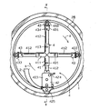
4は、螺旋管成形装置であり、螺旋管成形装置4は図3、4に示すように、中心部に設けられた取付フレーム41と、取付フレーム41から放射状に延設される4個の延長部の一つに装備される接合機構部42と、同じく取付フレーム41の他の延長部に装備される案内機構部43とからなる。
【0014】
取付フレーム41は管体411が十字状に溶接されて構成されている。管体411の管口に腕杆412が摺動、且つ回転自在に挿通され、固定ボルト413により固定されている。
接合機構部42には外部ロール421と内部ロール422が設けられ、これらの外部ロール421と内部ロール422を駆動回転する歯車機構が箱体423内に設けられ、歯車機構はハンドル424により駆動される。425は間隔保持用のスペーサーロールである。
【0015】
案内機構部43には短管状取付部材431が設けられ、取付部材431には枠体432が設けられ、枠体432には案内ロール433が転動可能に設けられている。434は取付部材431に設けられた固定ボルトである。
帯状板2は接合機構部42の外部ロール421と内部ロール422とにより相隣る一方の帯状板2の係合凹条21と他方の帯状板2の係合突条23とを係合させることにより断面円形の螺旋管26を形成するようになっている。
【0016】
この際、接合機構部42の外部ロール421と帯状板2のT形リブ24、24の間の凹溝との係合案内作用及び内部ロール422と帯状板2の係合凹条21との係合案内作用により外部ロール421と内部ロール422とは矢印aで示すように、螺旋管26の周方向に公転し、且つ、矢印bで示すように、螺旋管26の軸方向に移動する。同時に案内機構部43の案内ロール433と帯状板2の係合凹条21との係合案内作用により螺旋管成形装置4は前方に移動するようになっている。
【0017】
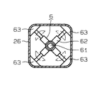
5は螺旋管26内であって既設管1の奥方向に推進移動する台車であり、台車5には芯軸支持部51が設けられ、芯軸支持部51には角形成形装置6の芯軸61が支持されている。
角形成形装置6は、図5に示すように、その芯軸61からアクチュエータ62により押し型63が放射方向に往復移動できるように設けられており、断面円形の螺旋管26は角形成形装置6に到り、押し型63により内面が押されて断面形状がほぼ正方形に成形され、断面四角形の螺旋管27に成形されるようになっている。
【0018】
次に、叙上の装置を使用して本発明更生方法を実施する態様について説明する。
ドラム3内から帯状板2が既設下水管1内に供給され、螺旋管成形装置4により相隣る一方の帯状板2の係合凹条21と他方の帯状板2の係合突条23とを係合させることにより断面円形の螺旋管26を形成し次いで、断面円形の螺旋管26を角形成形装置6により断面四角形の螺旋管27に成形し、断面四角形の螺旋管27により既設下水管1をライニングし、既設下水管1を更新する。
既設下水管1の内面と、挿入された四角形の螺旋管27との間に間隙が生じる場合には、裏込め材としてモルタルを注入する。
【0019】
以上、本発明の実施の形態を図により説明したが、本発明の具体的な構成は図示の実施の形態に限定されるものではなく、本発明の要旨を逸脱しない範囲の設計変更は本発明に含まれる。
例えば、図示の実施の形態においては、外部ロール421と内部ロール422はハンドル424によりを駆動回転するものであるが、動力により駆動回転するようにしてもよい。
【0020】
【発明の効果】
本発明既設管の更生方法においては、合成樹脂製帯状板を断面非円形の既設管内に挿入し、合成樹脂製帯状板を螺旋状に巻回し、合成樹脂製帯状板の端部同士を接合することにより断面円形の螺旋管を形成し、この断面円形の螺旋管を放射方向に往復移動できるように設けられた押し型により内面を押して断面四角形の螺旋管に成形して、断面非円形の既設管に適合する断面非円形に成形し、断面非円形の螺旋管により既設管をライニングするものであるから、断面非円形の既設管の内面と断面非円形の螺旋管外面との間に大きな間隙が生じることがなく、既設管内の流路断面積が大幅に減少する恐れはない。
【図面の簡単な説明】
【図1】 本発明既設管の更生方法の一実施態様例を示す説明図。
【図2】 本発明既設管の更生方法に使用する帯状体の一例を示す断面図。
【図3】 図1に示す本発明既設管の更生方法に使用する螺旋管成形装置を示す正面図。
【図4】 図3のIV−IV線における断面図。
【図5】 図1に示す本発明既設管の更生方法に使用する角形成形装置を示す正面図。
【符号の説明】
1 既設下水管
2 帯状板
21 係合凹条
23 係合凸条
24 T形リブ
25 補強材
26 断面円形の螺旋管
27 断面四角形の螺旋管
3 ドラム
4 螺旋管成形装置
5 台車
6 角形成形装置[0001]
BACKGROUND OF THE INVENTION
The present invention relates to a method for rehabilitating an existing pipe having a non-circular cross section such as a square cross section.
[0002]
[Prior art]
Conventionally, as described in, for example, Japanese Patent Laid-Open No. 2-245317, a synthetic resin belt-shaped plate in which an engagement groove is provided at one end and an engagement protrusion is provided at the other end. Are spirally fed, and a helical tube is formed by engaging the engaging recesses of one of the adjacent synthetic resin strips with the engaging protrusion of the other synthetic resin strip. There is known a method of rehabilitating an existing pipe by inserting the pipe into an existing pipe such as a metal pipe or a fume pipe and lining the existing pipe with a spiral pipe.
[0003]
[Problems to be solved by the invention]
However, in such a conventional method of rehabilitating existing pipes, there is no particular problem if the existing pipe has a normal circular cross section, but when the existing pipe has a non-circular shape such as a square cross section. When a spiral tube having a circular cross section is inserted into an existing tube having a non-circular cross section, a large gap is formed between the inner surface of the existing tube having a non-circular cross section and the outer surface of the spiral tube having a circular cross section. There is a problem that the area is greatly reduced and a predetermined flow rate cannot be secured.
[0004]
The present invention has been made by paying attention to such problems in the conventional method of rehabilitating existing pipes, and the object of the present invention is to solve the above problems and to greatly reduce the cross-sectional area of the flow path. The object is to provide a method for rehabilitating existing pipes that is not required.
[0005]
[Means for Solving the Problems]
In order to achieve the above object, the existing pipe rehabilitation method of the present invention is a method for rehabilitating an existing pipe in which the inner surface of an existing pipe having a non-circular cross-sectional shape is lined with a spiral pipe, and the synthetic resin belt-like plate is cross- Inserted into a circular existing tube, wound a synthetic resin strip in a spiral shape, joined the ends of the synthetic resin strip to form a circular tube with a circular cross section, The inner surface is pushed into a spiral tube with a square cross section by a push die provided so that it can reciprocate in the radial direction, and it is formed into a non-circular cross section that matches an existing pipe with a non-circular cross section. It is characterized by lining existing pipes.
[0006]
In the present invention, the material of the strip plate made of synthetic resin is not particularly limited as long as it can be used as it is for forming a helical tube. For example, a hard vinyl chloride resin is used. , Synthetic resins such as polyethylene, polypropylene, polyphenylene sulfide (PPS), nylon, and ABS resin can be used.
[0007]
In the present invention, as a method of forming a spiral tube by winding a synthetic resin strip in a spiral shape and joining the ends of the synthetic resin strip together, a conventionally employed apparatus can be used as it is. Although not particularly limited, for example, a synthetic resin belt-like plate having an engaging recess at one end and an engaging protrusion at the other end is spiral. The spiral tube may be formed by supplying and winding and engaging the engaging recesses of one of the adjacent synthetic resin strips and the engaging protrusion of the other synthetic resin strip.
[0008]
In order to form such a spiral tube, as described in Japanese Patent Publication No. 3-48392 and Japanese Patent Publication No. 3-10493, a synthetic resin strip is guided to a predetermined position by a guide roll, Engagement ridges of one synthetic resin belt-shaped plate adjacent to each other by the pressure roller introduced between the pressure-rolling rollers that sandwich the synthetic resin belt-shaped plate from the inside and outside, and the engagement ridges of the other synthetic resin belt-shaped plate And the helical tube may be formed by engaging the.
[0009]
[Action]
In the rehabilitation method for an existing pipe of the present invention, a synthetic resin strip is inserted into an existing pipe having a non-circular cross section, the synthetic resin strip is wound spirally, and the ends of the synthetic resin strip are joined together. By forming a spiral tube with a circular cross section, the inner surface of the spiral tube having a circular cross section is formed by a pressing die provided so as to be able to reciprocate in the radial direction. Since the existing pipe is lined with a non-circular spiral tube that conforms to the pipe, a large gap is formed between the inner surface of the non-circular existing pipe and the outer surface of the non-circular spiral pipe. Does not occur, and there is no fear that the channel cross-sectional area in the existing pipe will be significantly reduced.
[0010]
DETAILED DESCRIPTION OF THE INVENTION
Next, embodiments of the present invention will be described with reference to the drawings.
FIG. 1 is an explanatory view showing an embodiment of a method for rehabilitating an existing pipe of the present invention.
In FIG. 1, 1 is an existing sewer pipe (box culvert) to be rehabilitated, and the cross-sectional shape of the existing
[0011]
2 is a polyethylene belt-like plate. As shown in FIG. 2, the belt-
[0012]
Reference numeral 3 denotes a drum, in which the belt-
[0013]
[0014]
The
The
[0015]
The
In the belt-
[0016]
At this time, the engagement guide action of the
[0017]
5 is a cart within the
As shown in FIG. 5, the
[0018]
Next, a mode for carrying out the rehabilitation method of the present invention using the above apparatus will be described.
A belt-
When a gap is generated between the inner surface of the existing
[0019]
The embodiment of the present invention has been described above with reference to the drawings. However, the specific configuration of the present invention is not limited to the illustrated embodiment, and design changes within a scope not departing from the gist of the present invention can be made. include.
For example, in the illustrated embodiment, the
[0020]
【The invention's effect】
In the rehabilitation method for an existing pipe of the present invention, a synthetic resin strip is inserted into an existing pipe having a non-circular cross section, the synthetic resin strip is wound spirally, and the ends of the synthetic resin strip are joined together. By forming a spiral tube with a circular cross section, the inner surface is pushed into a spiral tube with a square cross section by a pressing die provided so that the circular tube with a circular cross section can be reciprocated in the radial direction. Since the existing pipe is lined with a non-circular spiral tube that conforms to the pipe, a large gap is formed between the inner surface of the non-circular existing pipe and the outer surface of the non-circular spiral pipe. Does not occur, and there is no fear that the channel cross-sectional area in the existing pipe will be significantly reduced.
[Brief description of the drawings]
FIG. 1 is an explanatory view showing an embodiment of a method for rehabilitating an existing pipe of the present invention.
FIG. 2 is a cross-sectional view showing an example of a band used in the method for rehabilitating an existing pipe of the present invention.
FIG. 3 is a front view showing a helical tube forming apparatus used in the method for rehabilitating the existing pipe of the present invention shown in FIG. 1;
4 is a cross-sectional view taken along line IV-IV in FIG. 3;
FIG. 5 is a front view showing the angulation apparatus used in the method for rehabilitating the existing pipe of the present invention shown in FIG. 1;
[Explanation of symbols]
DESCRIPTION OF
Claims (1)
Priority Applications (1)
| Application Number | Priority Date | Filing Date | Title |
|---|---|---|---|
| JP2116696A JP3676475B2 (en) | 1996-02-07 | 1996-02-07 | Rehabilitation of existing pipes |
Applications Claiming Priority (1)
| Application Number | Priority Date | Filing Date | Title |
|---|---|---|---|
| JP2116696A JP3676475B2 (en) | 1996-02-07 | 1996-02-07 | Rehabilitation of existing pipes |
Publications (2)
| Publication Number | Publication Date |
|---|---|
| JPH09207218A JPH09207218A (en) | 1997-08-12 |
| JP3676475B2 true JP3676475B2 (en) | 2005-07-27 |
Family
ID=12047336
Family Applications (1)
| Application Number | Title | Priority Date | Filing Date |
|---|---|---|---|
| JP2116696A Expired - Fee Related JP3676475B2 (en) | 1996-02-07 | 1996-02-07 | Rehabilitation of existing pipes |
Country Status (1)
| Country | Link |
|---|---|
| JP (1) | JP3676475B2 (en) |
Families Citing this family (2)
| Publication number | Priority date | Publication date | Assignee | Title |
|---|---|---|---|---|
| JP6922140B2 (en) * | 2017-07-05 | 2021-08-18 | タキロンシーアイ株式会社 | Inner surface material pressing device |
| JP6940098B2 (en) * | 2017-12-11 | 2021-09-22 | 株式会社クボタケミックス | Pipe making machine, pipe making method of pipe body and strip-shaped member |
-
1996
- 1996-02-07 JP JP2116696A patent/JP3676475B2/en not_active Expired - Fee Related
Also Published As
| Publication number | Publication date |
|---|---|
| JPH09207218A (en) | 1997-08-12 |
Similar Documents
| Publication | Publication Date | Title |
|---|---|---|
| JP6518324B2 (en) | Pipe forming apparatus for spiral pipe and pipe forming method | |
| JP3676475B2 (en) | Rehabilitation of existing pipes | |
| JP3072015B2 (en) | Lining construction equipment in sewer | |
| JP3216760B2 (en) | Lining construction equipment in sewer | |
| JP2019084728A (en) | Pipe manufacturing equipment for spiral tube | |
| JP3898862B2 (en) | Lining construction method in pipe and auxiliary equipment for construction | |
| JP6940098B2 (en) | Pipe making machine, pipe making method of pipe body and strip-shaped member | |
| JP2014113793A (en) | Lining method, conduit making machine used for the same, and renovation conduit line | |
| JPH08261363A (en) | Lining construction method and construction equipment for irregular cross section pipe | |
| JP3473999B2 (en) | How to insert a helical tube into a sheath tube | |
| JP3786506B2 (en) | Lining method for existing pipes | |
| JP7684653B2 (en) | Pipe making machine and pipe making method | |
| JP7679031B2 (en) | Pipe making machine and pipe making method | |
| JP7684654B2 (en) | Pipe making machine and pipe making method | |
| JPH10176771A (en) | Lining pipe making apparatus and shield secondary lining method | |
| JPH09207217A (en) | Rehabilitation method for existing pipes | |
| JP7602232B2 (en) | Pipe making machine and pipe making method | |
| JP2020029009A (en) | Existing pipe rehabilitation method and pipe making device | |
| JP2000096996A (en) | Backing material secondary lining method | |
| JP3634715B2 (en) | Middle push pipe for propulsion method of power cave | |
| JPH11188794A (en) | Construction method of lining pipe in sewer | |
| JPH1182865A (en) | Sewer lining method | |
| JP2002181236A (en) | Method and apparatus for lining lining in sewer | |
| JP2002113778A (en) | Lining method in sewer | |
| JPH09300466A (en) | Profile for existing pipe lining |
Legal Events
| Date | Code | Title | Description |
|---|---|---|---|
| A977 | Report on retrieval |
Effective date: 20040616 Free format text: JAPANESE INTERMEDIATE CODE: A971007 |
|
| A131 | Notification of reasons for refusal |
Effective date: 20040623 Free format text: JAPANESE INTERMEDIATE CODE: A131 |
|
| A521 | Written amendment |
Effective date: 20040819 Free format text: JAPANESE INTERMEDIATE CODE: A523 |
|
| TRDD | Decision of grant or rejection written | ||
| A01 | Written decision to grant a patent or to grant a registration (utility model) |
Free format text: JAPANESE INTERMEDIATE CODE: A01 Effective date: 20050413 |
|
| A61 | First payment of annual fees (during grant procedure) |
Free format text: JAPANESE INTERMEDIATE CODE: A61 Effective date: 20050428 |
|
| FPAY | Renewal fee payment (prs date is renewal date of database) |
Free format text: PAYMENT UNTIL: 20090513 Year of fee payment: 4 |
|
| FPAY | Renewal fee payment (prs date is renewal date of database) |
Year of fee payment: 4 Free format text: PAYMENT UNTIL: 20090513 |
|
| FPAY | Renewal fee payment (prs date is renewal date of database) |
Free format text: PAYMENT UNTIL: 20100513 Year of fee payment: 5 |
|
| FPAY | Renewal fee payment (prs date is renewal date of database) |
Year of fee payment: 6 Free format text: PAYMENT UNTIL: 20110513 |
|
| LAPS | Cancellation because of no payment of annual fees |