JP4419246B2 - Ventilation damper - Google Patents
Ventilation damper Download PDFInfo
- Publication number
- JP4419246B2 JP4419246B2 JP2000029831A JP2000029831A JP4419246B2 JP 4419246 B2 JP4419246 B2 JP 4419246B2 JP 2000029831 A JP2000029831 A JP 2000029831A JP 2000029831 A JP2000029831 A JP 2000029831A JP 4419246 B2 JP4419246 B2 JP 4419246B2
- Authority
- JP
- Japan
- Prior art keywords
- fin
- passage
- ventilation damper
- pair
- rotation
- Prior art date
- Legal status (The legal status is an assumption and is not a legal conclusion. Google has not performed a legal analysis and makes no representation as to the accuracy of the status listed.)
- Expired - Lifetime
Links
- 238000009423 ventilation Methods 0.000 title claims description 39
- 230000002441 reversible effect Effects 0.000 claims description 10
- 230000005540 biological transmission Effects 0.000 claims description 9
- 230000002093 peripheral effect Effects 0.000 description 7
- 238000004378 air conditioning Methods 0.000 description 6
- 239000000428 dust Substances 0.000 description 6
- 230000000903 blocking effect Effects 0.000 description 2
- 230000000295 complement effect Effects 0.000 description 2
- 238000001514 detection method Methods 0.000 description 1
- 238000010586 diagram Methods 0.000 description 1
- 238000006073 displacement reaction Methods 0.000 description 1
- 230000000694 effects Effects 0.000 description 1
- 239000002184 metal Substances 0.000 description 1
- 230000002265 prevention Effects 0.000 description 1
- 239000007787 solid Substances 0.000 description 1
Images


Landscapes
- Ventilation (AREA)
- Air-Flow Control Members (AREA)
Description
【0001】
【発明の属する技術分野】
本発明は、事務所ビル、集合住宅、戸建住宅、倉庫等の室内と室外との通気のために、これらの壁等に取り付けて通気の程度を制御する換気ダンパに関する。
【0002】
【発明が解決しようとする課題】
通常、この種の換気ダンパでは、通路を規定するフレーム内にフィンが回動自在に配され、フィンの回動により通路の開度を決定して、通路を介する通気の程度を制御するようにしている。
【0003】
斯かる換気ダンパにおいて、通路開放状態で室外において一定以上の風速の風が吹く等して室内外に大きな気圧差が生じると、通路を介して室内に対して必要以上に空気が導出入されて、室内に不快な空気流が生じると共に、室外の塵埃を室内に持ち込み、更には、室内を所定に温度設定した状態が大きく乱されて、これを補正するために空調消費電力の増大を招来する等の好ましくない事態が生じ得る。
【0004】
本発明は、前記諸点に鑑みてなされたものであって、その目的とするところは、室内外に大きな気圧差が生じて通路に一定以上の流速の空気流が生じる際には、この空気流を利用して自然に通路閉塞を行い得、而して、室内に不快な空気流が生じないようにできると共に室外の塵埃の室内への持ち込みをなくし得、しかも、空調消費電力の低減を図り得る換気ダンパを提供することにある。
【0005】
【課題を解決するための手段】
本発明の第一の態様の換気ダンパは、入口孔及び出口孔を有する通路を内部に有したフレームと、回動により通路を開閉するようにフレーム内に回動自在に配されたフィンと、このフィンによる通路開閉を行わせるべくフィンを回動させる回動手段とを具備しており、斯かる換気ダンパにおいて、回動手段は、回動力発生手段と、この回動力発生手段により発生された回動力をフィンに伝達する伝達手段とを具備しており、伝達手段は、フィンが通路開放位置に回動された際に、通路閉塞位置に向かうフィンの自由回動を許容するようになっており、フィンは、軸部と、この軸部から径方向に伸びた一対のフィン本体部とを具備していると共に、通路開放位置に向かって回動されるように常時付勢されており、フィン本体部の先端部は、通路を通過する空気流により通路閉塞位置に向かう回転モーメントをフィンに生じさせるように湾曲している。
【0006】
第一の態様の換気ダンパによれば、フィンが、通路開放位置に回動された際に、通路閉塞位置に向かうフィンの自由回動を許容するようになっていると共に、フィン本体部の先端部が、通路を通過する空気流により通路閉塞位置に向かう回転モーメントをフィンに生じさせるように湾曲しているために、フィンを通路開放位置に向かって常時回動付勢させる付勢力を適宜設定することにより、室内外に大きな気圧差が生じて通路に一定以上の流速の空気流、例えば3m/sec以上の空気流が生じる際に、この空気流を利用して自然に通路閉塞を行い得、而して、強風等により通路を介して室内に対して必要以上に空気が導出入されて、室内に不快な空気流が生じることをなくし得ると共に、室外の塵埃を室内に持ち込むようなことをなくし得、しかも、室内の空調状態が大きく乱されることがなく、空調消費電力の低減を図り得る。
【0007】
本発明の換気ダンパにおいて、好ましくは、第二の態様の換気ダンパのように、先端部及びその近傍でのフィン本体部の一方の面は、凸面となるように湾曲しており、その他方の面は、凹面となるように湾曲している。
【0008】
本発明の第三の態様の換気ダンパでは、第一又は第二の態様の換気ダンパにおいて、通路閉塞位置に向かうフィンの自由回動に抗する弾性手段を更に具備しており、フィンは、この弾性手段により通路開放位置に向かって回動されるように常時付勢されている。
【0009】
第三の態様の換気ダンパによれば、通路開放位置に向かうフィンの回動付勢を弾性手段により行うために、弾性手段の弾性力を適宜設定することにより、空気流を利用する自然な通路閉塞を確実に行うことができる。
【0010】
本発明の換気ダンパにおいて、伝達手段を、本発明の第四の態様の換気ダンパのように、フィンの軸方向の一端に配された円板状の鍔体に一端が取付けられた連結部材と、この連結部材の他端がフィンの回動方向に関して遊びをもって係合した円弧スリットを有していると共に回動力発生手段に連結された回転自在部材とを有して構成しても、参考の第五の態様の換気ダンパの例として、回動力発生手段に連結された回転自在部材と、円板状の鍔体に設けられた円弧スリットと、一端が回転自在部材に固着され、他端がフィンの回動方向に関して遊びをもって円弧スリットに係合した連結部材とを具備して構成してもよい。なお、第四又は第五の態様の換気ダンパのように伝達手段を構成すると共に第三の態様の弾性手段を設ける場合、当該弾性手段を、一端がフレームに、他端が円板状の鍔体に連結されたコイルばねを具備して構成するとよい。
【0011】
本発明の第六の態様の換気ダンパでは、第一から第五のいずれかの態様の換気ダンパにおいて、一方のフィン本体部は他方のフィン本体部よりも重く、フィンは、この一対のフィン本体部の重量の差違により通路開放位置に向かって回転されるように常時付勢されている。
【0012】
第六の態様の換気ダンパのように、通路開放位置に向かうフィンの回動付勢を一対のフィン本体部の重量の差違により行ってもよく、斯かる一対のフィン本体部の重量の差違を得るために、一対のフィン本体部を軸部に対して軸対称に形成すると共に、一方のフィン本体部を中実にして、他方のフィン本体部に空洞を設けるか、一方のフィン本体部に重りを付加するかし、更には、一対のフィン本体部が軸部に対して非対称になるように、一方のフィン本体部を他方のフィン本体部よりも長く形成してもよい。
【0013】
【発明の実施の形態】
次に本発明及びその実施の形態を、図に示す好ましい例を参照して更に詳細に説明する。なお、本発明はこの例に何等限定されないのである。
【0014】
図1から図7において、本例の換気ダンパ1は、入口孔2及び出口孔3を有する通路4を内部に有したフレーム5と、回動により通路4を開閉するようにフレーム5内に回動自在に配されたフィン6と、フィン6による通路4の開閉を行わせるべくフィン6を回動させる回動手段7と、フィン6の軸方向の両端に配された円板状の鍔体8及び9と、鍔体8及び9の夫々の外周面10及び11に常時接触すると共に、回動手段7によりフィン6が通路閉塞位置(図1に示す位置)に回動された際に、フィン6の軸方向の両縁部12及び13に接触するように、軸方向において通路4側に突出してフレーム5の両側に取付けられたゴム等の弾性体からなる一対の側部閉塞部材14及び15と、一対の側部閉塞部材14及び15を橋絡して、回動手段7によりフィン6が通路閉塞位置に回動された際に、フィン6の先端部16及び17に接触するように、フレーム5に取付けられたゴム等の弾性体からなる先端部閉塞部材18及び19とを具備している。
【0015】
フレーム5は、上部壁部31、上部壁部31に対して下方に対向して配された下部壁部32並びに互いに軸方向において対向する側壁部33及び34を一体的に具備しており、これら上部壁部31、下部壁部32並びに側壁部33及び34に囲まれて形成された入口孔2及び出口孔3を含む通路4が室外部35及び室内部36の夫々に、雨水侵入防止兼防鳥板37及び防塵網38の夫々を介して開口している。
【0016】
複数の庇及び開口を有した雨水侵入防止兼防鳥板37は、フレーム5が取付けられる横サッシ39及び40間に配されており、防塵網38は、フレーム5に取付けられている。
【0017】
フィン6は、中空の軸部41と、軸部41から径方向に且つ軸対称に一体的に伸びて形成された一対のフィン本体部42及び43とを具備しており、フィン本体部42及び43の夫々は、その先端部16及び17並びにその近傍で湾曲している。
【0018】
先端部16及びその近傍でのフィン本体部42の一方の面101は、後述の湾曲面83に向かって凸となるように、すなわち凸面となるように湾曲しており、その他方の面102は、面101に相補的な凹面となるように湾曲しており、同じく、先端部17及びその近傍でのフィン本体部43の一方の面103は、後述の湾曲面84に向かって凸となるように、すなわち凸面となるように湾曲しており、その他方の面104は、面103に相補的な凹面となるように湾曲している。斯かる先端部16及び17並びにその近傍でのフィン本体部42及び43の湾曲形状は、フィン6による通路4の開放状態(図2に示す位置)で通路4に空気流Aが生じる際に、フィン本体部42には湾曲面83に向かう揚力を、フィン本体部43には湾曲面84に向かう揚力を夫々生じさせ、この揚力に基づく回転モーメントでフィン6を通路閉塞位置に向かわせるように回転させることになる。
【0019】
フィン本体部42及び43の端面には、一体的に鍔体8及び9が固着されており、鍔体8及び9は、軸部41及び一対のフィン本体部42及び43の夫々の対応の端面に密に接触している。鍔体8は、小径鍔部44と、大径鍔部53とを一体に有しており、鍔部9も、小径鍔部45と、大径鍔部54とを一体に有している。大径鍔部54には回転軸52の一端が固着されており、大径鍔部53には一体的に軸方向に伸びた筒部46が形成されている。
【0020】
回動手段7は、回動力発生手段としての可逆電動モータ61と、可逆電動モータ61により発生された回動力をフィン6に伝達する伝達手段62とを具備している。可逆電動モータ61は、フレーム5に連接された基台63に取付けられており、伝達手段62は、基台63に取付けられて、可逆電動モータ61の出力回転軸の回転を減速する減速歯車機構64と、減速歯車機構64の出力軸に連結されており、基台63に軸受65を介して回転自在に支持された回転自在軸51と、回転自在軸51に固着された円盤状の回転自在部材47と、回転自在部材47に形成された一対の円弧スリット48及び49の夫々に、夫々の一端がフィン6の回転方向に関して遊びをもって係合し、夫々の他端が大径鍔部53に一体に取付けられた連結部材としての一対の円柱状のピン50及び55と、フィン6が通路開放位置に回動された際に、当該通路閉塞位置に向かうフィン6の自由回動に抗する弾性手段20とを具備している。円弧スリット48及び49は、軸対称に回転自在部材47に形成されており、ピン50及び55もまた、軸対称に大径鍔部53に植設されている。
【0021】
弾性手段20は、一端56が鍔体8の大径鍔部53に、他端57が連結金具58を介してフレーム5の側壁部33に連結されて、筒部46の周りに配された捩じりコイルばね59を具備しており、連結金具58は、一端がねじ60を介して側壁部33に固着されており、他端にコイルばね59の他端57が掛け止めされており、コイルばね59は、通路4の開放位置に向かってフィン6を回動させるように、鍔体8の大径鍔部53を常時弾性的に付勢している。而して、フィン6は、コイルばね59により通路4の開放位置に向かって回動されるように常時付勢されている。
【0022】
回動手段7は、可逆電動モータ61の作動により減速歯車機構64、回転自在軸51を介して回転自在部材47を回転させ、回転自在部材47の回転で、円弧スリット48及び49の夫々に、夫々の一端が係合する円柱状のピン50及び55を介して大径鍔部53を回転させて、これにより通路4を開閉するようにフィン6を回動させるようになっている。
【0023】
大径鍔部53及び54の夫々は、側壁部33及び34の夫々に回転自在に支持されており、大径鍔部53及び54の夫々の外周面と当該大径鍔部53及び54が配される円孔を規定する側壁部33及び34の夫々の内周面との間には、Oリング71及び73が配されている。
【0024】
大径鍔部54に固着されている回転自在軸52は、フレーム5に連接された基台75に軸受76を介して回転自在に支持されている。
【0025】
軸部41に関して対称に配されて側壁部33に固着された一対の側部閉塞部材14の夫々は、鍔体8の小径鍔部44の外周面10に常時接触する円弧面77及び78を有していると共に、フィン6が通路閉塞位置に回動された際に、フィン6の軸方向の縁部12であるフィン本体部42及び43の夫々の軸方向の縁部に接触する平面81及び82並びに当該平面81及び82に連接した湾曲面83及び84を有している。
【0026】
軸部41に関して対称に配されて側壁部34に固着された一対の側部閉塞部材15の夫々もまた、一対の側部閉塞部材14の夫々と同様に、鍔体9の小径鍔部45の外周面11に常時接触する円弧面(図示せず)を有していると共に、フィン6が通路閉塞位置に回動された際に、フィン6の軸方向の縁部13であるフィン本体部42及び43の夫々の軸方向の縁部に接触する平面(図示せず)並びに当該平面に連接した湾曲面(図示せず)を有している。
【0027】
先端部閉塞部材18は、上部壁部31側の側部閉塞部材14と15との間では、上部壁部31に嵌着されており、その両端部では、上部壁部31側の側部閉塞部材14及び15に夫々嵌着されており、先端部閉塞部材19は、下部壁部32側の側部閉塞部材14と15との間では、下部壁部32に嵌着されており、その両端部では、下部壁部32側の側部閉塞部材14及び15に嵌着されている。
【0028】
換気ダンパ1は、フィン6が通路4を閉塞した状態(図1、図6及び図7に示す位置)から通路4を開放した状態(図2、図8及び図9に示す位置)までの当該フィン6の位置を夫々検出する検出器(図示せず)を更に具備しており、可逆電動モータ61は、これら検出器からの検出信号に基づいて、その作動が制御されてフィン6による通路4の開度を所定の値にするようになっている。
【0029】
以上の換気ダンパ1では、図2、図8及び図9に示す通路4の全開位置で、可逆電動モータ61が作動されてその出力回転軸が正転されると、フィン6は、円弧スリット48及び49の夫々とピン50及び55の夫々との係合を介して、回動されて、図1に示すようにその両縁部12及び13が側部閉塞部材14及び15に夫々接触し、その先端部16及び17が先端部閉塞部材18及び19に夫々接触して、通路4を閉塞する状態に配される。この状態では、通路4を介しての空気の流通はフィン6により阻止されることになる。
【0030】
図1、図6及び図7に示すフィン6の状態から、可逆電動モータ61が作動されてその出力回転軸26が逆転されると、コイルばね59の弾性力に付勢されて、フィン6は回動されて、図2、図8及び図9に示す通路4を全開する状態に配される。この状態では、通路4を介して室外部35及び室内部36の空気は、流通されることになる。
【0031】
換気ダンパ1では、図2、図8及び図9に示すように、フィン6が通路開放位置に回動された際に、通路閉塞位置に向かうフィン6の自由回動を許容するようになっていると共に、コイルばね59が通路閉塞位置に向かうフィン6の自由回動に抗するようになっているために、コイルばね59の弾性力を適宜設定することにより、室内外36及び35の大きな気圧差に基づいて室外35から室内36への又は室内36から室外35への一定以上の流速の空気流A、例えば3m/sec以上の空気流Aが通路4に生じる際には、通路閉塞位置に向かう方向にフィン6を自然に回動させることができ、而して、室外35の強風等に起因する室内外36及び35の大きな気圧差により通路4を介して室内36に対して必要以上に空気が導出入されて、室内36に不快な空気流Aが生じることをなくし得ると共に、室外35の塵埃を室内36に持ち込むようなことをなくし得、しかも、空調電力低減を図り得る。更に、換気ダンパ1では、先端部16及び17並びにその近傍でフィン本体部42及び43が上述のように湾曲しているために、通路4での空気流Aにより一定方向の回転モーメントがフィン6に生じる結果、一定以上の流速の空気流A、例えば3m/sec以上の空気流Aで確実に通路4を閉塞できることになる。
【0032】
また、換気ダンパ1においては、フィン6の軸方向の両端面をフレーム5の側壁部33及び34に隙間なしに配置しなくても、通路4を完全閉塞できると共に、フィン6若しくはフレーム5の熱膨張又はそれらの多少の変形、変位でも、通路開閉のためのフィン6の回動を滑らかに行い得て、騒音等が生じたりする虞がない。
【0033】
更に、換気ダンパ1の側部閉塞部材14及び15並びに先端部閉塞部材18及び19が弾性体からなるために、フィン6の両縁部12及び13と先端部16及び17とをこれらに弾性反力をもってぴったりと押し付けることができるために、より完全に通路4を閉塞することができる。加えて、換気ダンパ1の側部閉塞部材14及び15と対応の鍔体8及び9の外周面10及び11とが円弧面接触するために、側部閉塞部材14及び15と鍔体8及び9の外周面10及び11とを介する空気洩れを完全になくすことができる。
【0034】
その上、換気ダンパ1では、側部閉塞部材14及び15とフィン6との夫々が湾曲面を有して、この湾曲面同士で互いに接触するために、接触面積が広くなり、通路閉塞をより完全に達成できる。
【0035】
なお、換気ダンパ1では、電動によりフィン6を回動させると共に、通路4を傾斜させ、そして入口孔2及び出口孔3を夫々水平方向に開口させたが、本発明はこれらに限定されず、例えば、手動でフィン6を回動させるようにし、また、通路4を水平に伸びるようにしてもよく、更に、出口孔3を垂直方向に開口させてもよい。
【0036】
【発明の効果】
本発明によれば、室内外に大きな気圧差が生じて通路に一定以上の流速の空気流が生じる際には、この空気流を利用して自然に通路閉塞を行い得、而して、室内に不快な空気流が生じないようにできると共に室外の塵埃の室内への持ち込みをなくし得、しかも、空調消費電力の低減を図り得る換気ダンパを提供することができる。
【図面の簡単な説明】
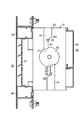
【図1】本発明の好ましい実施の形態の例の通路閉鎖状態の縦断面図である。
【図2】図1に示す例の通路開放状態の縦断面図である。
【図3】図1に示す例のフィンを省いた縦断面図である。
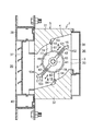
【図4】図1に示す例の室内部からの説明図である。
【図5】図1に示す例の室内部からの拡大説明図である。
【図6】フィンによる通路閉塞状態での図4に示すVI−VI線矢視断面図である。
【図7】フィンによる通路閉塞状態での図4に示すVII−VII線矢視断面図である。
【図8】フィンによる通路開放状態での図4に示すVI−VI線矢視断面図である。
【図9】フィンによる通路開放状態での図4に示すVII−VII線矢視断面図である。
【符号の説明】
1 換気ダンパ
2 入口孔
3 出口孔
4 通路
5 フレーム
6 フィン
7 回動手段
20 弾性手段
48、49 円弧スリット
50、55 ピン
62 伝達手段[0001]
BACKGROUND OF THE INVENTION
The present invention relates to a ventilation damper that is attached to these walls or the like and controls the degree of ventilation for ventilation between indoors and outdoors such as office buildings, apartment houses, detached houses, and warehouses.
[0002]
[Problems to be solved by the invention]
Usually, in this type of ventilation damper, fins are rotatably arranged in a frame defining the passage, and the degree of ventilation through the passage is controlled by determining the opening degree of the passage by the rotation of the fin. ing.
[0003]
In such a ventilation damper, when a large air pressure difference occurs outside the room due to a wind of a certain speed or more outside in the outdoor state when the passage is open, air is led in and out of the room more than necessary through the passage. An unpleasant air flow is generated in the room, dust outside the room is brought into the room, and a state in which the room is set to a predetermined temperature is greatly disturbed, and an increase in air-conditioning power consumption is caused to correct this. Such an unfavorable situation may occur.
[0004]
The present invention has been made in view of the above-mentioned points. The object of the present invention is to generate an air flow at a flow rate higher than a certain level in the passage due to a large pressure difference between the room and the outside. It is possible to naturally block the passage by using air, and to prevent unpleasant air flow in the room and to eliminate the introduction of dust outside the room, and to reduce air-conditioning power consumption. It is to provide a ventilation damper that gets.
[0005]
[Means for Solving the Problems]
The ventilation damper of the first aspect of the present invention includes a frame having a passage having an inlet hole and an outlet hole therein, a fin that is rotatably disposed in the frame so as to open and close the passage by rotation, A rotating means for rotating the fin to open and close the passage by the fin. In such a ventilation damper, the rotating means is generated by the rotating power generating means and the rotating power generating means. Transmission means for transmitting the rotational force to the fin, and the transmission means allows the fin to freely rotate toward the passage closing position when the fin is turned to the passage opening position. The fin has a shaft portion and a pair of fin main body portions extending in the radial direction from the shaft portion, and is always urged to rotate toward the passage opening position. The tip of the fin body is the passage The rotational moment toward the passage closed position is curved so as to cause the fins by an air flow passing through.
[0006]
According to the ventilation damper of the first aspect, when the fin is rotated to the passage opening position, the fin is allowed to freely rotate toward the passage closing position, and the front end of the fin main body portion. Since the part is curved so that a rotational moment toward the passage closing position is generated in the fin by the air flow passing through the passage, an urging force for constantly urging the fin toward the passage opening position is appropriately set. By doing so, when a large pressure difference occurs inside and outside of the room and an air flow having a flow velocity above a certain level, for example, an air flow of 3 m / sec or more, is generated, the passage can be naturally blocked using this air flow. Therefore, it is possible to prevent air from being unnecessarily introduced into the room through the passage due to strong winds and the like, and uncomfortable airflow to occur in the room, and to bring outdoor dust into the room. Lost , Moreover, without indoor air conditioning state is disturbed greatly, can work to reduce the air-conditioning power consumption.
[0007]
In the ventilation damper of the present invention, preferably, as in the ventilation damper of the second aspect, one surface of the fin body portion in the vicinity of the tip portion and its vicinity is curved so as to be a convex surface, The surface is curved to be a concave surface.
[0008]
In the ventilation damper of the third aspect of the present invention, the ventilation damper of the first or second aspect further includes elastic means that resists free rotation of the fin toward the passage closing position. It is always urged to be rotated toward the passage opening position by the elastic means.
[0009]
According to the ventilation damper of the third aspect, the natural passage using the air flow is set by appropriately setting the elastic force of the elastic means in order to bias the fin toward the passage opening position by the elastic means. Occlusion can be reliably performed.
[0010]
In the ventilation damper of the present invention, as in the ventilation damper of the fourth aspect of the present invention, the transmission means includes a connecting member having one end attached to a disk-shaped housing disposed at one end in the axial direction of the fin. Even if the other end of the connecting member has an arc slit engaged with play in the rotation direction of the fin and a rotatable member connected to the rotational force generating means, As an example of the ventilation damper of the fifth aspect, a rotatable member connected to the rotational power generating means, an arc slit provided in a disk-shaped housing, one end fixed to the rotatable member, and the other end You may comprise and comprise the connection member engaged with the circular arc slit with play about the rotation direction of the fin. When the transmission means is configured as in the ventilation damper of the fourth or fifth aspect and the elastic means of the third aspect is provided, the elastic means is attached to the frame at one end and the disc-shaped flange at the other end. A coil spring connected to the body may be provided.
[0011]
In the ventilation damper of the sixth aspect of the present invention, in the ventilation damper of any one of the first to fifth aspects, one fin main body is heavier than the other fin main body, and the fin is a pair of fin main bodies. It is always urged to rotate toward the passage opening position due to the difference in weight of the parts.
[0012]
As in the ventilation damper of the sixth aspect, the rotational biasing of the fins toward the passage opening position may be performed by the difference in the weights of the pair of fin body parts, and the difference in the weights of the pair of fin body parts In order to obtain, a pair of fin main body portions are formed symmetrically with respect to the shaft portion, and one fin main body portion is solid, and a cavity is provided in the other fin main body portion, or in one fin main body portion A weight may be added, and further, one fin body part may be formed longer than the other fin body part so that the pair of fin body parts are asymmetric with respect to the shaft part.
[0013]
DETAILED DESCRIPTION OF THE INVENTION
Next, the present invention and its embodiments will be described in more detail with reference to preferred examples shown in the drawings. The present invention is not limited to this example.
[0014]
1 to 7, the ventilation damper 1 of the present example includes a
[0015]
The
[0016]
The rainwater intrusion prevention / bird-
[0017]
The
[0018]
One
[0019]
The
[0020]
The rotating means 7 includes a reversible
[0021]
The elastic means 20 has one
[0022]
The rotating means 7 rotates the
[0023]
Each of the large-
[0024]
The
[0025]
Each of the pair of
[0026]
Each of the pair of
[0027]
The front
[0028]
The ventilation damper 1 is in the state from the state in which the
[0029]
In the ventilation damper 1 described above, when the reversible
[0030]
When the reversible
[0031]
In the ventilation damper 1, as shown in FIGS. 2, 8, and 9, when the
[0032]
Further, in the ventilation damper 1, the
[0033]
Further, since the
[0034]
In addition, in the ventilation damper 1, the
[0035]
In the ventilation damper 1, the
[0036]
【The invention's effect】
According to the present invention, when a large air pressure difference occurs outside the room and an air flow with a flow velocity above a certain level is generated in the passage, the air flow can be used to naturally block the passage, It is possible to provide a ventilation damper that can prevent an unpleasant air flow from being generated and can eliminate the entry of outdoor dust into the room, and can reduce power consumption of air conditioning.
[Brief description of the drawings]
FIG. 1 is a longitudinal sectional view of an example of a preferred embodiment of the present invention in a closed passage state.
FIG. 2 is a longitudinal sectional view of the example shown in FIG.
FIG. 3 is a longitudinal sectional view of the example shown in FIG. 1 with the fins omitted.
FIG. 4 is an explanatory diagram from the inside of the example shown in FIG. 1;
FIG. 5 is an enlarged explanatory view from the indoor portion of the example shown in FIG. 1;
6 is a cross-sectional view taken along line VI-VI shown in FIG. 4 in a state where a passage is closed by a fin.
7 is a cross-sectional view taken along line VII-VII shown in FIG. 4 in a state in which a passage is blocked by a fin.
8 is a cross-sectional view taken along line VI-VI shown in FIG. 4 in a state in which a passage is opened by a fin.
9 is a cross-sectional view taken along the line VII-VII shown in FIG.
[Explanation of symbols]
DESCRIPTION OF SYMBOLS 1
Claims (4)
Priority Applications (1)
| Application Number | Priority Date | Filing Date | Title |
|---|---|---|---|
| JP2000029831A JP4419246B2 (en) | 2000-02-07 | 2000-02-07 | Ventilation damper |
Applications Claiming Priority (1)
| Application Number | Priority Date | Filing Date | Title |
|---|---|---|---|
| JP2000029831A JP4419246B2 (en) | 2000-02-07 | 2000-02-07 | Ventilation damper |
Related Child Applications (1)
| Application Number | Title | Priority Date | Filing Date |
|---|---|---|---|
| JP2009223549A Division JP4780227B2 (en) | 2009-09-28 | 2009-09-28 | Ventilation damper |
Publications (2)
| Publication Number | Publication Date |
|---|---|
| JP2001221492A JP2001221492A (en) | 2001-08-17 |
| JP4419246B2 true JP4419246B2 (en) | 2010-02-24 |
Family
ID=18554928
Family Applications (1)
| Application Number | Title | Priority Date | Filing Date |
|---|---|---|---|
| JP2000029831A Expired - Lifetime JP4419246B2 (en) | 2000-02-07 | 2000-02-07 | Ventilation damper |
Country Status (1)
| Country | Link |
|---|---|
| JP (1) | JP4419246B2 (en) |
Families Citing this family (5)
| Publication number | Priority date | Publication date | Assignee | Title |
|---|---|---|---|---|
| JP5023418B2 (en) * | 2001-07-05 | 2012-09-12 | 株式会社日本設計 | Ventilation equipment |
| JP2003083600A (en) * | 2001-09-06 | 2003-03-19 | Nishimatsu Constr Co Ltd | Damper |
| JP4984710B2 (en) * | 2006-07-24 | 2012-07-25 | マックス株式会社 | Air conditioner |
| JP2015111022A (en) * | 2013-12-06 | 2015-06-18 | オイレスEco株式会社 | Ventilation damper |
| JP2014157012A (en) * | 2014-05-14 | 2014-08-28 | Oiles Eco Corp | Ventilation damper |
-
2000
- 2000-02-07 JP JP2000029831A patent/JP4419246B2/en not_active Expired - Lifetime
Also Published As
| Publication number | Publication date |
|---|---|
| JP2001221492A (en) | 2001-08-17 |
Similar Documents
| Publication | Publication Date | Title |
|---|---|---|
| KR101317441B1 (en) | Damper for ventilation | |
| JP4419246B2 (en) | Ventilation damper | |
| JP2014157012A (en) | Ventilation damper | |
| KR101415526B1 (en) | Louver system having forced exhaust and natural ventilation | |
| JP4780227B2 (en) | Ventilation damper | |
| JP4362918B2 (en) | Ventilation damper | |
| JP4655391B2 (en) | Ventilation damper | |
| JP4586244B2 (en) | Ventilation damper | |
| JP2000304345A (en) | Air supply damper | |
| KR20120076987A (en) | Duct damper with opening/closing structure utilizing spring | |
| JP5023418B2 (en) | Ventilation equipment | |
| JP3988537B2 (en) | Ventilation equipment | |
| JP4797268B2 (en) | Ventilation equipment | |
| JPH06207732A (en) | Shutter of duct ventilation apparatus | |
| JP4373140B2 (en) | Ventilation unit | |
| CN218820822U (en) | Air regenerating device with baffle mechanism | |
| JP4151429B2 (en) | Ventilation damper | |
| JP2005188426A (en) | Air conditioner plug fan room | |
| CN115077088A (en) | Airflow non-return device for fresh air conditioner and fresh air conditioner | |
| JP4118643B2 (en) | Ventilation structure | |
| CN214093170U (en) | Scavenger fan check valve structure and scavenger fan | |
| JP4734744B2 (en) | Ventilation damper | |
| JP3448453B2 (en) | Building ventilation device and method of setting the ventilation device | |
| JP4568699B2 (en) | Ventilation equipment | |
| JP4453347B2 (en) | Ventilation equipment |
Legal Events
| Date | Code | Title | Description |
|---|---|---|---|
| A621 | Written request for application examination |
Free format text: JAPANESE INTERMEDIATE CODE: A621 Effective date: 20070205 |
|
| A977 | Report on retrieval |
Free format text: JAPANESE INTERMEDIATE CODE: A971007 Effective date: 20090714 |
|
| A131 | Notification of reasons for refusal |
Free format text: JAPANESE INTERMEDIATE CODE: A131 Effective date: 20090728 |
|
| A521 | Written amendment |
Free format text: JAPANESE INTERMEDIATE CODE: A523 Effective date: 20090928 |
|
| TRDD | Decision of grant or rejection written | ||
| A01 | Written decision to grant a patent or to grant a registration (utility model) |
Free format text: JAPANESE INTERMEDIATE CODE: A01 Effective date: 20091110 |
|
| A01 | Written decision to grant a patent or to grant a registration (utility model) |
Free format text: JAPANESE INTERMEDIATE CODE: A01 |
|
| FPAY | Renewal fee payment (event date is renewal date of database) |
Free format text: PAYMENT UNTIL: 20121211 Year of fee payment: 3 |
|
| R150 | Certificate of patent or registration of utility model |
Ref document number: 4419246 Country of ref document: JP Free format text: JAPANESE INTERMEDIATE CODE: R150 Free format text: JAPANESE INTERMEDIATE CODE: R150 |
|
| A61 | First payment of annual fees (during grant procedure) |
Free format text: JAPANESE INTERMEDIATE CODE: A61 Effective date: 20091123 |
|
| FPAY | Renewal fee payment (event date is renewal date of database) |
Free format text: PAYMENT UNTIL: 20131211 Year of fee payment: 4 |
|
| R250 | Receipt of annual fees |
Free format text: JAPANESE INTERMEDIATE CODE: R250 |
|
| R250 | Receipt of annual fees |
Free format text: JAPANESE INTERMEDIATE CODE: R250 |
|
| R250 | Receipt of annual fees |
Free format text: JAPANESE INTERMEDIATE CODE: R250 |
|
| R250 | Receipt of annual fees |
Free format text: JAPANESE INTERMEDIATE CODE: R250 |
|
| R250 | Receipt of annual fees |
Free format text: JAPANESE INTERMEDIATE CODE: R250 |
|
| R250 | Receipt of annual fees |
Free format text: JAPANESE INTERMEDIATE CODE: R250 |
|
| R250 | Receipt of annual fees |
Free format text: JAPANESE INTERMEDIATE CODE: R250 |
|
| R250 | Receipt of annual fees |
Free format text: JAPANESE INTERMEDIATE CODE: R250 |
|
| EXPY | Cancellation because of completion of term |