JP4878541B2 - 動力伝達装置 - Google Patents
動力伝達装置 Download PDFInfo
- Publication number
- JP4878541B2 JP4878541B2 JP2006294851A JP2006294851A JP4878541B2 JP 4878541 B2 JP4878541 B2 JP 4878541B2 JP 2006294851 A JP2006294851 A JP 2006294851A JP 2006294851 A JP2006294851 A JP 2006294851A JP 4878541 B2 JP4878541 B2 JP 4878541B2
- Authority
- JP
- Japan
- Prior art keywords
- power transmission
- case
- case portion
- diameter gear
- opening
- Prior art date
- Legal status (The legal status is an assumption and is not a legal conclusion. Google has not performed a legal analysis and makes no representation as to the accuracy of the status listed.)
- Expired - Fee Related
Links
- 230000005540 biological transmission Effects 0.000 title claims description 25
- 230000002093 peripheral effect Effects 0.000 claims description 23
- 230000008878 coupling Effects 0.000 claims description 5
- 238000010168 coupling process Methods 0.000 claims description 5
- 238000005859 coupling reaction Methods 0.000 claims description 5
- 230000004048 modification Effects 0.000 description 6
- 238000012986 modification Methods 0.000 description 6
- 239000000463 material Substances 0.000 description 5
- XEEYBQQBJWHFJM-UHFFFAOYSA-N Iron Chemical compound [Fe] XEEYBQQBJWHFJM-UHFFFAOYSA-N 0.000 description 4
- 230000000694 effects Effects 0.000 description 2
- 238000003780 insertion Methods 0.000 description 2
- 230000037431 insertion Effects 0.000 description 2
- 229910052742 iron Inorganic materials 0.000 description 2
- XAGFODPZIPBFFR-UHFFFAOYSA-N aluminium Chemical compound [Al] XAGFODPZIPBFFR-UHFFFAOYSA-N 0.000 description 1
- 229910052782 aluminium Inorganic materials 0.000 description 1
- 239000000428 dust Substances 0.000 description 1
- 239000002828 fuel tank Substances 0.000 description 1
- 230000036316 preload Effects 0.000 description 1
- 238000007789 sealing Methods 0.000 description 1
- 238000003466 welding Methods 0.000 description 1
Images


Landscapes
- Gear Transmission (AREA)
- General Details Of Gearings (AREA)
Description
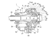
図1は、動力分配機構の断面図、図2は、同側面図である。
分配ケース5は、ボルト挿通部7,9,11,13,15,17等を備え、ボルト挿通部7,9,11,13,15,17等に挿通したボルトによりトランスミッション側のベル・ハウジングに取り付けられている。
分配ケース5内には、フロント・デファレンシャル装置のデフ・ケースから回転部材である連結中空軸19が延設されている。連結中空軸19は、中間軸3の外周に嵌合している。
連結中空軸19には、一端側外周に結合用のスプライン部20が設けられ、他端側内周にセンタリング部21が設けられている。センタリング部21は、中間軸3をセンタリングしている。センタリング部21には、軸方向にオイルを導く螺旋溝23が形成されている。
雄ねじ部63には、固定部としてナット64が締結され、第2のケース部分57の緩み止めが行われている。従って、第1のケース部分55に対する第2のケース部分57の螺合の緩みを規制する固定部を設けた構成となっている。
環状壁部65の先端には、環状のシール壁部69が設けられている。シール壁部69は、前記リング・ギヤ25の軸方向に突設され前記開口61の内周側に嵌合する。シール壁部69は、回転軸方向でベアリングであるテーパー・ローラ・ベアリング35よりもリング・ギヤ25側に突出した構成となっている。シール壁部69は、回転部材である連結中空軸19のフランジ部24の半径方向に対向している。この対向により、配置スペースの軸方向のコンパクト化に寄与している。シール壁部69を、リング・ギヤ25の半径方向に対向する構成にすることで、配置スペースをさらに有効活用することができる。
第3のケース部分59は、第1のケース部分55に結合されている。第3のケース部分59には、軸受け収容部83が設けられ、前記テーパー・ローラ・ベアリング53が支持されている。従って、分配ケース5は、ピニオン・ギヤ29を支持する第3のケース部分59を備えた構成となっている。
分配ケース5の内部には、オイルが収容されている。
[動力伝達]
フロント・デファレンシャル装置のデフ・ケースへ入力された駆動力は、左右
サイド・ギヤへ伝達されると共に、連結中空軸19、リング・ギヤ25、ピニオン・ギヤ29、後輪側出力軸27へと分配される。
フロント・デファレンシャル装置のサイド・ギヤからは、中間軸3を介して一方の前輪車軸へ出力される。
本発明実施例1では、リング・ギヤ25及びピニオン・ギヤ29を有するギヤ組31と、前記ギヤ組31を収容すると共に端部にリング・ギヤ25を回転軸方向から組み付け可能とする開口61を有する第1のケース部分55と、前記開口61に取り付けられて分配ケース5を構成する第2のケース部分57とを有し、前記開口61の内周側に、前記第2のケース部分57を螺合により結合したため、図2のように開口61の外周側にボルトを取り付けるためのスペースの確保が不要となり、他部材、例えばエンジンとのスペースの取り合いを抑制し、設計的な自由度を拡げることができる。
第1のケース部分55に対する第2のケース部分57の螺合の緩みを規制するナット64を設けたため、第1のケース部分55に対する第2のケース部分57の確実な固定を行わせることができる。
第1のケース部分55に対する第2のケース部分57の螺合は、前記第2のケース部分57を前記リング・ギヤ25の回転軸方向で位置調整可能とするため、テーパー・ローラー・ベアリング33,35のプリロード調整が容易であり、組み付け性、分解性の向上を図ることができる。
図3,図4は、固定部の変形例を示す要部拡大断面図である。
第2のケース部分57Aのシール壁部69Aは、フランジ部24Aに対し半径方向に対向している。
本実施例の凹部71A及びオーリング73Aは、第1のケース部分55A側に設けられている。
[その他]
上記実施例では、第2のケース部分を、第1のケース部分の開口内周側に螺合する構成としたが、開口外周側に螺合する構成であっても、ボルトによる結合に比較して外周への張り出しを抑制することができる。
1A 終減速装置(動力伝達装置)
5 分配ケース(ケース)
5A キャリヤ・ケース(ケース)
25,25A リング・ギヤ(大径ギヤ)
29 ピニオン・ギヤ(小径ギヤ)
29A ドライブ・ピニオン・ギヤ(小径ギヤ)
31,31A ギヤ組
35,35A テーパー・ローラー・ベアリング(ベアリング)
59 第3のケース部分
61,61A 開口
64 ナット(固定部)
65,65A 環状壁部
69,69A シール壁部
73,73A オーリング(オイル・シール)
85 ピン(固定部)
87 スナップ・リング(固定部)
Claims (8)
- 大径ギヤ及び小径ギヤを有するギヤ組と、
前記ギヤ組を収容すると共に端部に大径ギヤを回転軸方向から組み付け可能とする開口を有する第1のケース部分と、
前記開口に取り付けられてケースを構成する第2のケース部分とを有し、
前記開口の内周側に、前記第2のケース部分を嵌合又は螺合により結合し、
この嵌合又は螺合は、前記第2のケース部分の外周部と前記第1のケース部分の開口の端部内周との間の結合固定を含み、
この端部内周の結合固定の内周側に前記第2のケース部分の壁部を備え、
この第2のケース部分の壁部の内周部に前記大径ギヤが固定された回転部材を支持するための軸受を収容する軸受け収容部を備えた、
ことを特徴とする動力伝達装置。 - 請求項1記載の動力伝達装置であって、
前記第2のケース部分に、前記開口の内周側に嵌合又は螺合する環状壁部を備え、
前記環状壁部の先端に、前記大径ギヤの軸方向に突設され前記開口の内周側に嵌合する環状のシール壁部を設け、
前記開口の内周側と前記シール壁部との間に、オイルの流通を阻止するオイルシールを設け、
前記ケースの内部に、オイルを収容した、
ことを特徴とする動力伝達装置。 - 請求項2記載の動力伝達構造であって、
前記大径ギヤは、前記第2のケース部分にベアリングを介して回転自在に支持され、
前記シール壁部は、回転軸方向で前記ベアリングよりも大径ギヤ側に位置する、
ことを特徴とする動力伝達装置。 - 請求項2記載の動力伝達構造であって、
前記大径ギヤは、回転部材に一体回転可能に固定され、
前記シール壁部は、前記大径ギヤ又は回転部材の半径方向に対向している、
ことを特徴とする動力伝達装置。 - 請求項1〜4の何れかに記載の動力伝達構造であって、
前記第1のケース部分に対する第2のケース部分の嵌合又は螺合の抜け又は緩みを規制する固定部を設けた、
ことを特徴とする動力伝達装置。 - 請求項1〜5の何れかに記載の動力伝達構造であって、
前記第1のケース部分に対する第2のケース部分の螺合は、前記第2のケース部分を前記大径ギヤの回転軸方向で第1のケース部分に対して位置調整可能とする、
ことを特徴とする動力伝達装置。 - 請求項1記載の動力伝達構造であって、
前記ギヤ組は、ベベル・ギヤ組であり、
前記大径ギヤは、リング・ギヤであり、
前記小径ギヤは、ピニオンである、
ことを特徴とする動力伝達装置。 - 請求項7記載の動力伝達構造であって、
前記ケースは、前記ピニオンを支持する第3のケース部分を備えた、
ことを特徴とする動力伝達装置。
Priority Applications (1)
| Application Number | Priority Date | Filing Date | Title |
|---|---|---|---|
| JP2006294851A JP4878541B2 (ja) | 2006-10-30 | 2006-10-30 | 動力伝達装置 |
Applications Claiming Priority (1)
| Application Number | Priority Date | Filing Date | Title |
|---|---|---|---|
| JP2006294851A JP4878541B2 (ja) | 2006-10-30 | 2006-10-30 | 動力伝達装置 |
Publications (3)
| Publication Number | Publication Date |
|---|---|
| JP2008111487A JP2008111487A (ja) | 2008-05-15 |
| JP2008111487A5 JP2008111487A5 (ja) | 2009-11-12 |
| JP4878541B2 true JP4878541B2 (ja) | 2012-02-15 |
Family
ID=39444105
Family Applications (1)
| Application Number | Title | Priority Date | Filing Date |
|---|---|---|---|
| JP2006294851A Expired - Fee Related JP4878541B2 (ja) | 2006-10-30 | 2006-10-30 | 動力伝達装置 |
Country Status (1)
| Country | Link |
|---|---|
| JP (1) | JP4878541B2 (ja) |
Family Cites Families (10)
| Publication number | Priority date | Publication date | Assignee | Title |
|---|---|---|---|---|
| JPS50123774A (ja) * | 1974-03-12 | 1975-09-29 | ||
| JPS5934157A (ja) * | 1982-08-19 | 1984-02-24 | Nippon Denso Co Ltd | 機械式回転数指示計器 |
| JP2757180B2 (ja) * | 1985-08-22 | 1998-05-25 | スズキ株式会社 | 差動機収容ケース |
| JPS6259130A (ja) * | 1985-09-06 | 1987-03-14 | Nissan Motor Co Ltd | 4輪駆動装置 |
| JPS63170659A (ja) * | 1987-01-09 | 1988-07-14 | Canon Inc | 電子写真用トナ− |
| JPS63195470A (ja) * | 1987-02-06 | 1988-08-12 | Toyota Motor Corp | 車輌用動力伝達装置の出力軸の軸受の潤滑装置 |
| JPH0415353A (ja) * | 1990-05-09 | 1992-01-20 | Tochigi Fuji Ind Co Ltd | 動力伝達装置 |
| JP4421006B2 (ja) * | 1999-05-06 | 2010-02-24 | 株式会社電業社機械製作所 | 立軸渦巻ポンプ |
| US7231847B2 (en) * | 2005-03-28 | 2007-06-19 | American Axle & Manufacturing, Inc. | Axle assembly with threaded cover pan attachment and method of assembly |
| JP2007071306A (ja) * | 2005-09-07 | 2007-03-22 | Toyota Motor Corp | デファレンシャルハウジング |
-
2006
- 2006-10-30 JP JP2006294851A patent/JP4878541B2/ja not_active Expired - Fee Related
Also Published As
| Publication number | Publication date |
|---|---|
| JP2008111487A (ja) | 2008-05-15 |
Similar Documents
| Publication | Publication Date | Title |
|---|---|---|
| US8764601B2 (en) | Carrier with center backbone and dual lateral cases | |
| EP2412554B1 (en) | In-wheel motor unit | |
| US20050277480A1 (en) | Flange assembly for supporting a bearing and an end fitting in a driveshaft assembly | |
| JP5212710B2 (ja) | 車輪用軸受装置 | |
| JP2010151155A (ja) | アイドラギヤ支持構造 | |
| JP4878541B2 (ja) | 動力伝達装置 | |
| JP6905359B2 (ja) | モータ及びピニオン軸の組み付け方法 | |
| US20230256805A1 (en) | Power transmission apparatus for hybrid vehicle | |
| JP2009041650A (ja) | 歯車装置 | |
| EP4299354A1 (en) | Wheel end assembly | |
| JP5613419B2 (ja) | 動力伝達装置 | |
| JP5247861B2 (ja) | 動力伝達装置 | |
| JP5225208B2 (ja) | 動力伝達装置 | |
| JP2005225255A (ja) | 駆動軸の支持構造 | |
| JP2020090980A (ja) | 推進軸 | |
| JP2019132389A (ja) | 差動装置 | |
| JP7675392B2 (ja) | プロペラシャフト | |
| JP2008005576A (ja) | ギヤドモータ及びロボット用ギヤドモータ | |
| JP6852635B2 (ja) | 減速機一体型ハブ機構 | |
| JP2016056887A (ja) | 動力伝達装置 | |
| JP6962809B2 (ja) | 車両用推進軸 | |
| JP2007192326A (ja) | 動力伝達装置 | |
| JP2020132037A (ja) | インホイールモータ駆動装置 | |
| JP2012051406A (ja) | ラックアンドピニオン式ステアリングギヤユニット | |
| JP2008208947A (ja) | 歯車装置 |
Legal Events
| Date | Code | Title | Description |
|---|---|---|---|
| A521 | Written amendment |
Free format text: JAPANESE INTERMEDIATE CODE: A523 Effective date: 20090924 |
|
| A621 | Written request for application examination |
Free format text: JAPANESE INTERMEDIATE CODE: A621 Effective date: 20090924 |
|
| A977 | Report on retrieval |
Free format text: JAPANESE INTERMEDIATE CODE: A971007 Effective date: 20110214 |
|
| A131 | Notification of reasons for refusal |
Free format text: JAPANESE INTERMEDIATE CODE: A131 Effective date: 20110329 |
|
| A521 | Written amendment |
Free format text: JAPANESE INTERMEDIATE CODE: A523 Effective date: 20110519 |
|
| TRDD | Decision of grant or rejection written | ||
| A01 | Written decision to grant a patent or to grant a registration (utility model) |
Free format text: JAPANESE INTERMEDIATE CODE: A01 Effective date: 20111122 |
|
| A01 | Written decision to grant a patent or to grant a registration (utility model) |
Free format text: JAPANESE INTERMEDIATE CODE: A01 |
|
| A61 | First payment of annual fees (during grant procedure) |
Free format text: JAPANESE INTERMEDIATE CODE: A61 Effective date: 20111128 |
|
| R150 | Certificate of patent or registration of utility model |
Ref document number: 4878541 Country of ref document: JP Free format text: JAPANESE INTERMEDIATE CODE: R150 Free format text: JAPANESE INTERMEDIATE CODE: R150 |
|
| FPAY | Renewal fee payment (event date is renewal date of database) |
Free format text: PAYMENT UNTIL: 20141209 Year of fee payment: 3 |
|
| R250 | Receipt of annual fees |
Free format text: JAPANESE INTERMEDIATE CODE: R250 |
|
| R250 | Receipt of annual fees |
Free format text: JAPANESE INTERMEDIATE CODE: R250 |
|
| R250 | Receipt of annual fees |
Free format text: JAPANESE INTERMEDIATE CODE: R250 |
|
| LAPS | Cancellation because of no payment of annual fees |