JP4884898B2 - シリンダ錠 - Google Patents
シリンダ錠 Download PDFInfo
- Publication number
- JP4884898B2 JP4884898B2 JP2006253003A JP2006253003A JP4884898B2 JP 4884898 B2 JP4884898 B2 JP 4884898B2 JP 2006253003 A JP2006253003 A JP 2006253003A JP 2006253003 A JP2006253003 A JP 2006253003A JP 4884898 B2 JP4884898 B2 JP 4884898B2
- Authority
- JP
- Japan
- Prior art keywords
- cylinder
- tumbler
- magnet
- inner cylinder
- key
- Prior art date
- Legal status (The legal status is an assumption and is not a legal conclusion. Google has not performed a legal analysis and makes no representation as to the accuracy of the status listed.)
- Expired - Fee Related
Links
- 239000000463 material Substances 0.000 claims description 16
- 229910000831 Steel Inorganic materials 0.000 claims description 14
- 239000010959 steel Substances 0.000 claims description 14
- 239000002184 metal Substances 0.000 claims description 12
- 229910052751 metal Inorganic materials 0.000 claims description 12
- 239000000696 magnetic material Substances 0.000 claims description 11
- 230000004308 accommodation Effects 0.000 claims description 5
- 230000005389 magnetism Effects 0.000 claims description 2
- 230000006835 compression Effects 0.000 description 8
- 238000007906 compression Methods 0.000 description 8
- 230000002265 prevention Effects 0.000 description 8
- 238000005553 drilling Methods 0.000 description 6
- 229910001220 stainless steel Inorganic materials 0.000 description 5
- 239000010935 stainless steel Substances 0.000 description 5
- 230000007257 malfunction Effects 0.000 description 4
- -1 for example Substances 0.000 description 3
- 239000007769 metal material Substances 0.000 description 3
- 229910001369 Brass Inorganic materials 0.000 description 2
- PXHVJJICTQNCMI-UHFFFAOYSA-N Nickel Chemical compound [Ni] PXHVJJICTQNCMI-UHFFFAOYSA-N 0.000 description 2
- 239000010951 brass Substances 0.000 description 2
- 238000001179 sorption measurement Methods 0.000 description 2
- 229910000760 Hardened steel Inorganic materials 0.000 description 1
- 230000007547 defect Effects 0.000 description 1
- 230000001066 destructive effect Effects 0.000 description 1
- 238000000605 extraction Methods 0.000 description 1
- 238000003780 insertion Methods 0.000 description 1
- 230000037431 insertion Effects 0.000 description 1
- 238000000034 method Methods 0.000 description 1
- 230000004048 modification Effects 0.000 description 1
- 238000012986 modification Methods 0.000 description 1
- 229910052759 nickel Inorganic materials 0.000 description 1
- 230000002093 peripheral effect Effects 0.000 description 1
- 238000007747 plating Methods 0.000 description 1
- 238000010791 quenching Methods 0.000 description 1
- 230000000171 quenching effect Effects 0.000 description 1
- 229910000859 α-Fe Inorganic materials 0.000 description 1
Images


Landscapes
- Lock And Its Accessories (AREA)
Description
本発明の請求項1記載のシリンダ錠は、施錠開閉体に固定される外筒33と、
鍵穴35を有して該外筒33に回動自在に内設される内筒37と、
前記外筒33と該内筒37との境界上にわたるよう配置され前記外筒33に対する前記内筒37の回動を規制するとともに、前記鍵穴35に挿入された合鍵65によって前記境界を形成する位置へ移動されることで前記内筒37の回動規制を解除するタンブラ41、59と、を備え、
前記タンブラ41,59の少なくとも一つが、前記合鍵65に設けられた磁石69の同極反発力によって前記境界を形成する位置へ移動されるマグネットタンブラ59であるシリンダ錠100であって、
前記内筒37が焼き入れ硬質鋼材を素材とする磁性を有する金属からなり、
該内筒37に穿設される貫通穴に、非磁性体からなり有底筒形状のホルダ53が嵌入され、
該ホルダ53の収容室55は前記外筒33に穿設された貫通穴57と一致し、前記収容室55と前記貫通穴57とに前記マグネットタンブラ59が可動自在に収容されており、
該マグネットタンブラ59は、前記ホルダ53の底部53aによって前記鍵穴35の内部と遮蔽されていることを特徴とする。
該収容室55A,55B,55Cのそれぞれに、前記マグネットタンブラ59A,59B,59Cが収容されたことを特徴とする。
前記外筒33の先端に、前記凸状二次曲面71に連続する表出面73aを有した焼き入れ硬質鋼材からなるハードキャップ73が前記外筒33の軸線回りに空転自在に冠着されたことを特徴とする。
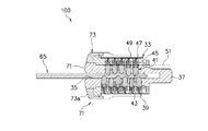
図1は本発明に係るシリンダ錠の平断面図、図2は図1に示したシリンダ錠の側断面図、図3は図1に示した合鍵の平面視を(a)、側面視を(b)に示した説明図、図4は合鍵抜脱時の内筒と外筒の平断面図、図5は合鍵挿入時のシリンダ錠の要部拡大平断面図、図6は合鍵抜脱時のシリンダ錠の要部拡大平断面図である。
本実施の形態に係るシリンダ錠100は、施錠開閉体(扉など)に固定された図示しない外装筒の内側に、外筒33を相対回転不能に装着する。外筒33の内部には、鍵穴35を有した内筒37を回動自在に内設している。内筒37は、硬質な金属素材で磁性体である金属、例えばステンレス鋼(SUS420F)からなり好ましくは焼き入れ処理を施している。外筒33と内筒37とには、図2に示すように、両者に亘って半径方向に貫通穴39を穿設している。この貫通穴39は、一端が鍵穴35の内部で開口し、他端が外筒33の外周面に開口している。貫通穴39は、鍵穴35の軸線方向に沿って複数配設される。
合鍵65の非挿入時(図6の状態)には、タンブラピン41は、圧縮スプリング47によって付勢され、先端を鍵穴35に突出させている。また、それぞれのタンブラピン41のシアライン51は、不連続となり、その結果ドライバピン45が外筒33と内筒37との境界部分に位置している。このため、内筒37は、外筒33に対して回動が規制されている。また、マグネットタンブラ59も、図6に示すように、ドライバピン63がシアライン51に位置し、内筒37の回動を規制している。
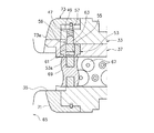
なお、本発明に係るシリンダ錠は、図7に示すように、ホルダ53Aに、内筒37の軸線に沿う方向で複数の収容室55A,55B,55Cが設けられ、収容室55A,55B,55Cのそれぞれに、マグネットタンブラ59A,59B,59Cが収容されるものであってもよい。このような構成によるシリンダ錠100Aによれば、一つのホルダ53Aを内筒37に嵌入することで、同時に複数のマグネットタンブラ59A,59B,59Cを収容でき、簡単な組み立て作業でカギ違い数を増やすことができ、安全性、防犯性能を容易に高めることができる。
35…鍵穴
37…内筒
41…タンブラ(タンブラピン)
53…ホルダ
55…収容室
59…マグネットタンブラ
65…合鍵
67…ディンプル
69…磁石
71…凸状二次曲面
73…ハードキャップ
73a…凸状二次曲面に連続する表出面
100…シリンダ錠
Claims (4)
- 施錠開閉体に固定される外筒と、
鍵穴を有して該外筒に回動自在に内設される内筒と、
前記外筒と該内筒との境界上にわたるよう配置され前記外筒に対する前記内筒の回動を規制するとともに、前記鍵穴に挿入された合鍵によって前記境界を形成する位置へ移動されることで前記内筒の回動規制を解除するタンブラと、を備え、
前記タンブラの少なくとも一つが、前記合鍵に設けられた磁石の同極反発力によって前記境界を形成する位置へ移動されるマグネットタンブラであるシリンダ錠であって、
前記内筒が焼き入れ硬質鋼材を素材とする磁性を有する金属からなり、
該内筒に穿設される貫通穴に、非磁性体からなり有底筒形状のホルダが嵌入され、
該ホルダの収容室は前記外筒に穿設された貫通穴と一致し、前記収容室と前記貫通穴とに前記マグネットタンブラが可動自在に収容されており、
該マグネットタンブラは、前記ホルダの底部によって前記鍵穴の内部と遮蔽されていることを特徴とするシリンダ錠。 - 前記マグネットタンブラ以外のタンブラが、前記合鍵の表裏面の少なくとも一方の面に複数凹設された所定のディンプルに対応して可動されることで前記境界を形成する位置へ移動されることを特徴とする請求項1記載のシリンダ錠。
- 前記ホルダに、前記内筒の軸線に沿う方向で複数の収容室が設けられ、
該収容室のそれぞれに、前記マグネットタンブラが収容されたことを特徴とする請求項1又は2記載のシリンダ錠。 - 前記内筒の先端表出面が、前記鍵穴を頂きとした凸状二次曲面で形成され、
前記外筒の先端に、前記凸状二次曲面に連続する表出面を有した焼き入れ硬質鋼材からなるハードキャップが前記外筒の軸線回りに空転自在に冠着されたことを特徴とする請求項1,2,3のいずれか1つに記載のシリンダ錠。
Priority Applications (1)
| Application Number | Priority Date | Filing Date | Title |
|---|---|---|---|
| JP2006253003A JP4884898B2 (ja) | 2006-09-19 | 2006-09-19 | シリンダ錠 |
Applications Claiming Priority (1)
| Application Number | Priority Date | Filing Date | Title |
|---|---|---|---|
| JP2006253003A JP4884898B2 (ja) | 2006-09-19 | 2006-09-19 | シリンダ錠 |
Publications (2)
| Publication Number | Publication Date |
|---|---|
| JP2008075273A JP2008075273A (ja) | 2008-04-03 |
| JP4884898B2 true JP4884898B2 (ja) | 2012-02-29 |
Family
ID=39347620
Family Applications (1)
| Application Number | Title | Priority Date | Filing Date |
|---|---|---|---|
| JP2006253003A Expired - Fee Related JP4884898B2 (ja) | 2006-09-19 | 2006-09-19 | シリンダ錠 |
Country Status (1)
| Country | Link |
|---|---|
| JP (1) | JP4884898B2 (ja) |
Family Cites Families (7)
| Publication number | Priority date | Publication date | Assignee | Title |
|---|---|---|---|---|
| JPS62268480A (ja) * | 1986-05-14 | 1987-11-21 | 太田興業株式会社 | シリンダ錠 |
| JPH09296636A (ja) * | 1996-05-07 | 1997-11-18 | Clover:Kk | 錠 |
| JPH1061268A (ja) * | 1996-08-22 | 1998-03-03 | Sanpou Lock Co Ltd | ドリル破壊防止錠 |
| JP3375542B2 (ja) * | 1998-05-13 | 2003-02-10 | 美和ロック株式会社 | 開閉扉用シリンダー錠 |
| JP4360515B2 (ja) * | 2001-02-22 | 2009-11-11 | 美和ロック株式会社 | マグネットシリンダ錠 |
| JP4138298B2 (ja) * | 2001-11-09 | 2008-08-27 | 美和ロック株式会社 | 錠装置 |
| JP4246005B2 (ja) * | 2003-07-03 | 2009-04-02 | 株式会社アルファ | シリンダ錠セット |
-
2006
- 2006-09-19 JP JP2006253003A patent/JP4884898B2/ja not_active Expired - Fee Related
Also Published As
| Publication number | Publication date |
|---|---|
| JP2008075273A (ja) | 2008-04-03 |
Similar Documents
| Publication | Publication Date | Title |
|---|---|---|
| US3967479A (en) | Key lock | |
| US7000441B2 (en) | Lock cylinder assembly | |
| US10533345B2 (en) | Electronic locking device | |
| JP4875738B2 (ja) | 鍵穴隠れ式解錠装置 | |
| AU2018332493B2 (en) | Locking device | |
| JP2009228283A (ja) | シリンダ錠の保護装置 | |
| US6446475B1 (en) | Switchlock assembly with snap-in cam | |
| KR200460718Y1 (ko) | 안심 자물쇠 | |
| JP4884898B2 (ja) | シリンダ錠 | |
| TW201323696A (zh) | 鎖具防盜裝置及用於該裝置之鑰匙 | |
| CA3183156A1 (en) | Electronic padlock | |
| US20100024499A1 (en) | High Security Cylinder Lock | |
| GB2413152A (en) | Cylinder lock with master key capability | |
| JP4138298B2 (ja) | 錠装置 | |
| CN102022034B (zh) | 隐藏钥匙孔的开锁装置 | |
| JP4112201B2 (ja) | 錠構造 | |
| US11230859B2 (en) | Magnetic keyed lock | |
| JP2003232145A (ja) | 複合型シリンダ錠 | |
| JP7780928B2 (ja) | シリンダ錠及びドア | |
| RU2785937C2 (ru) | Запирающее устройство с устройством защиты от постороннего вмешательства и ключом | |
| EP3578743A1 (en) | An electronic locking device | |
| JP4478528B2 (ja) | ケース用施錠装置 | |
| JP2006045770A (ja) | ケース用施錠装置 | |
| KR200263131Y1 (ko) | 실린더자물쇠 | |
| JP4832216B2 (ja) | サムターン |
Legal Events
| Date | Code | Title | Description |
|---|---|---|---|
| A621 | Written request for application examination |
Free format text: JAPANESE INTERMEDIATE CODE: A621 Effective date: 20090918 |
|
| A977 | Report on retrieval |
Free format text: JAPANESE INTERMEDIATE CODE: A971007 Effective date: 20110905 |
|
| A131 | Notification of reasons for refusal |
Free format text: JAPANESE INTERMEDIATE CODE: A131 Effective date: 20110913 |
|
| A521 | Written amendment |
Free format text: JAPANESE INTERMEDIATE CODE: A523 Effective date: 20111111 |
|
| TRDD | Decision of grant or rejection written | ||
| A01 | Written decision to grant a patent or to grant a registration (utility model) |
Free format text: JAPANESE INTERMEDIATE CODE: A01 Effective date: 20111206 |
|
| A01 | Written decision to grant a patent or to grant a registration (utility model) |
Free format text: JAPANESE INTERMEDIATE CODE: A01 |
|
| A61 | First payment of annual fees (during grant procedure) |
Free format text: JAPANESE INTERMEDIATE CODE: A61 Effective date: 20111207 |
|
| FPAY | Renewal fee payment (event date is renewal date of database) |
Free format text: PAYMENT UNTIL: 20141216 Year of fee payment: 3 |
|
| R150 | Certificate of patent or registration of utility model |
Free format text: JAPANESE INTERMEDIATE CODE: R150 |
|
| R250 | Receipt of annual fees |
Free format text: JAPANESE INTERMEDIATE CODE: R250 |
|
| R250 | Receipt of annual fees |
Free format text: JAPANESE INTERMEDIATE CODE: R250 |
|
| LAPS | Cancellation because of no payment of annual fees |