JP4982273B2 - Data display method of molding machine - Google Patents
Data display method of molding machine Download PDFInfo
- Publication number
- JP4982273B2 JP4982273B2 JP2007178520A JP2007178520A JP4982273B2 JP 4982273 B2 JP4982273 B2 JP 4982273B2 JP 2007178520 A JP2007178520 A JP 2007178520A JP 2007178520 A JP2007178520 A JP 2007178520A JP 4982273 B2 JP4982273 B2 JP 4982273B2
- Authority
- JP
- Japan
- Prior art keywords
- torque
- mold
- graph data
- mold closing
- value
- Prior art date
- Legal status (The legal status is an assumption and is not a legal conclusion. Google has not performed a legal analysis and makes no representation as to the accuracy of the status listed.)
- Active
Links
Images


Landscapes
- Moulds For Moulding Plastics Or The Like (AREA)
- Injection Moulding Of Plastics Or The Like (AREA)
Description
本発明は、トグルリンク式型締装置の作動時に検出したモータのトルクに係わるグラフデータを表示する際に用いて好適な成形機のデータ表示方法に関する。 The present invention relates to a data display method for a molding machine suitable for use in displaying graph data relating to motor torque detected during operation of a toggle link type mold clamping device.
サーボモータとボールねじ機構を有する駆動部を備え、この駆動部の進退運動をトグルリンク機構により可動盤に伝達するトグルリンク式型締装置を搭載した射出成形機は知られている。ところで、この種の型締装置では、型閉時に可動型と固定型間に異物が挟まった場合、金型を損傷する虞れがあるため、異物の有無を監視(検出)する監視区間(金型保護区間)を型閉工程の後段に設定している。 2. Description of the Related Art An injection molding machine equipped with a toggle link type mold clamping device that includes a drive unit having a servo motor and a ball screw mechanism and transmits the advance / retreat movement of the drive unit to a movable platen by a toggle link mechanism is known. By the way, in this type of mold clamping device, there is a risk of damaging the mold if a foreign object is caught between the movable mold and the fixed mold when the mold is closed. The mold protection section is set after the mold closing process.
従来、このような監視区間における異物の有無を監視する方法としては、特許文献1で開示される射出成形機の異物検出方法及び特許文献2で開示される射出成形機の型締制御方法が知られている。
Conventionally, as a method for monitoring the presence or absence of foreign matter in such a monitoring section, a foreign matter detection method for an injection molding machine disclosed in Patent Document 1 and a mold clamping control method for an injection molding machine disclosed in
前者の異物検出方法は、型締工程における監視区間の型閉動作に伴う物理量を検出するとともに、当該物理量の検出値と予め設定した設定値との偏差が予め設定した閾値以上になったなら異物検出処理を行うものであり、特に、予め試型締を行うことにより当該偏差の最大値を検出し、この最大値を予め設定した基準値に加算することにより閾値を設定する。また、監視区間では、サーボ回路にトルク制限信号を付与することにより、予め設定したトルク制限値となるようにトルク出力を制限し、可動型と固定型間に異物が挟まることにより金型に無理な加圧力が付加される弊害を防止している。したがって、この際のトルク制限値は、手動で設定する固定のトルク制限値となる。 The former foreign object detection method detects a physical quantity associated with the mold closing operation in the monitoring section in the mold clamping process, and if the deviation between the detected value of the physical quantity and a preset set value exceeds a preset threshold value, the foreign substance is detected. A detection process is performed, and in particular, a maximum value of the deviation is detected by performing trial mold clamping in advance, and a threshold is set by adding the maximum value to a preset reference value. In the monitoring section, a torque limit signal is given to the servo circuit to limit the torque output so that the torque limit value is set in advance. This prevents the harmful effect of applying a large pressure. Accordingly, the torque limit value at this time is a fixed torque limit value set manually.
後者の型締制御方法は、型締工程の型閉動作に対して設定した所定の監視区間における負荷トルクを検出するとともに、検出により得たトルク検出値が、設定したトルク制限値に達したなら、このトルク制限値を越えないようにトルク制御を行うに際し、自動設定モードを設け、この自動設定モードにより、監視区間におけるトルク検出値を、予め設定したサンプリング周期により順次検出し、かつ予め設定したショット回数分だけ検出するとともに、得られたトルク検出値から、各サンプリング順位毎のトルク制限値を所定の演算式により求めて自動設定するものである。したがって、この際のトルク制限値は、所定の条件に対応して変動する自動で設定されるトルク制限値となる。
しかし、上述した監視区間(金型保護区間)において異物を監視する従来の方法は、次のような解決すべき課題が存在した。 However, the conventional method for monitoring foreign matter in the monitoring section (mold protection section) described above has the following problems to be solved.
即ち、従来の方法は、いずれも監視区間の監視対象にモータのトルクを用いている。金型に異物が挟まった場合、これに対応してモータのトルク(負荷)が上昇するため、閾値を設定することにより異物の有無を検出(監視)できる。監視区間の設定は異物の監視を目的とするため、型締装置の種類に拘わらず、モータのトルクを監視すれば、異物の有無を監視する目的を十分に達成できる。 In other words, all of the conventional methods use the motor torque as the monitoring target in the monitoring section. When a foreign object is caught in the mold, the torque (load) of the motor increases correspondingly, and therefore the presence or absence of the foreign object can be detected (monitored) by setting a threshold value. Since the monitoring section is set for the purpose of monitoring foreign matter, the purpose of monitoring the presence or absence of foreign matter can be sufficiently achieved by monitoring the motor torque regardless of the type of mold clamping device.
ところで、型締装置は、その型締原理に着目した場合、直圧式型締装置とトグルリンク式型締装置が存在する。直圧式型締装置は、金型における実際の型閉力が型締機構を駆動するモータのトルクに対して正比例的に変化するため、型閉力に対する拡大率は変化しないが、トグルリンク式型締装置は、実際の型閉力がトグルリンク機構を駆動するモータのトルクに対して所定の拡大率により増圧されるため、監視区間の終端付近では相当の型閉力が発生する。 By the way, when the mold clamping device pays attention to the mold clamping principle, there are a direct pressure type mold clamping device and a toggle link type mold clamping device. In the direct pressure type mold clamping device, since the actual mold closing force in the mold changes in direct proportion to the torque of the motor that drives the mold clamping mechanism, the enlargement ratio for the mold closing force does not change. In the clamping device, the actual mold closing force is increased by a predetermined expansion rate with respect to the torque of the motor that drives the toggle link mechanism, so that a considerable mold closing force is generated near the end of the monitoring section.
一方、異物の有無を監視するトルク制限値や閾値の大きさ或いは監視条件等は、成形品の種類や成形条件等に応じてユーザーサイドで設定する必要がある。したがって、例えば、直圧式型締装置を搭載する射出成形機のユーザーが、トグルリンク式型締装置を搭載した新規の射出成形機を導入したような場合、直圧式型締装置を使用していた際における異物の有無を監視するトルク制限値(閾値)及び監視条件等の設定に係わるノウハウや感覚(勘)を利用できなくなる。結局、設定作業が面倒かつ設定時間が長時間化し、作業能率の低下を来すのみならず、反って不適切な設定或いは誤設定を招く虞れもあるなど、確実な金型保護を図る観点からは不十分となる。 On the other hand, it is necessary to set the torque limit value for monitoring the presence or absence of foreign matter, the size of the threshold or the monitoring conditions on the user side according to the type of the molded product, the molding conditions, and the like. Therefore, for example, when a user of an injection molding machine equipped with a direct pressure type clamping device introduces a new injection molding machine equipped with a toggle link type clamping device, the direct pressure type clamping device was used. The know-how and feeling (intuition) related to the setting of the torque limit value (threshold value) and the monitoring condition for monitoring the presence or absence of foreign matter at the time cannot be used. After all, the setting work is troublesome and the setting time is prolonged, which not only decreases the work efficiency, but also leads to inappropriate setting or incorrect setting, which can lead to reliable mold protection. Is not enough.
本発明は、このような背景技術に存在する課題を解決した成形機のデータ表示方法の提供を目的とするものである。 An object of the present invention is to provide a data display method for a molding machine that solves the problems existing in the background art.
本発明に係る成形機のデータ表示方法は、上述した課題を解決するため、モータ2により駆動するトグルリンク機構3を介して金型Cの型開閉及び型締を行う型締装置Mcの作動時に、モータ2のトルクTを所定のサンプリング間隔で検出し、少なくとも検出したトルクTに係わるグラフデータDtd,Dtc,Dtsをディスプレイ4に表示するに際し、少なくともトルクTに係わるグラフデータDtd,Dtc,Dtsに、トルク実測値Tdに係わるグラフデータDtdに加え、少なくとも手動で設定する固定のトルク制限値Tsc及び/又は所定の条件に対応して変動する自動で設定されるトルク制限値Tssに係わるグラフデータDtc,Dts,トルク指令値に係わるグラフデータ,の少なくとも一つ以上を含ませるとともに、当該トルクTに係わるグラフデータグラフデータDtd,Dtc,Dtsを金型Cの型閉力Fに係わるグラフデータDfd,Dfc,Dfsに変換し、かつトルクTの検出時における金型Cの型閉位置Xを、予め設定した、正常な型閉時における型閉時間tと型閉位置Xの関係を登録したデータベース5から求めるとともに、型閉位置Xに対する型閉力Fに係わるグラフデータDfd,Dfc,Dfsを、トルクTに係わるグラフデータDtd,Dtc,Dtsの表示に代えて、又はトルクTに係わるグラフデータDtd,Dtc,Dtsの表示に加えて、ディスプレイ4に表示するようにしたことを特徴とする。
In order to solve the above-described problem, the data display method of the molding machine according to the present invention operates when a mold clamping device Mc that opens / closes and molds the mold C via the
この場合、発明の好適な態様により、トルクTに係わるグラフデータDtd,Dtc,Dtsから金型Cの型閉力Fに係わるグラフデータDfd,Dfc,Dfsへの変換は、予め設定した所定の演算式(102)を用いることができる。 In this case, according to a preferred aspect of the invention, the conversion from the graph data Dtd, Dtc, Dts related to the torque T to the graph data Dfd, Dfc, Dfs related to the mold closing force F of the mold C is performed by a predetermined calculation. Equation (102) can be used.
このような手法による本発明に係る成形機のデータ表示方法によれば、次のような顕著な効果を奏する。 According to the data display method of the molding machine according to the present invention by such a method, the following remarkable effects are obtained.
(1) トグルリンク式型締装置Mcであっても、金型Cにおける実際の型閉力Fの大きさを容易かつ正確に把握できる。したがって、各種設定作業の容易化及び迅速化による作業能率向上に寄与できるとともに、より確実な金型保護を実現できる。特に、直圧式型締装置からトグルリンク式型締装置に変更したような場合でも、ユーザーは異物の有無を監視する際のトルク制限値や閾値及び監視条件等の設定を容易かつ的確に行うことができる。 (1) Even with the toggle link type mold clamping device Mc, the magnitude of the actual mold closing force F in the mold C can be easily and accurately grasped. Therefore, it is possible to contribute to improvement in work efficiency by facilitating and speeding up various setting operations, and it is possible to realize more reliable mold protection. In particular, even when the direct pressure type clamping device is changed to the toggle link type clamping device, the user can easily and accurately set the torque limit value, threshold value, monitoring condition, etc. when monitoring the presence or absence of foreign matter. Can do.
(2) トルクTに係わるグラフデータDtd,Dtc,Dtsには、トルク実測値Tdに係わるグラフデータDtdに加え、トルク制限値Tsc,Tssに係わるグラフデータDtc,Dts,トルク指令値に係わるグラフデータ,の少なくとも一つ以上を含ませるようにしたため、実際に発生する型閉力Fの大きさとトルク制限値Tsc,Tss或いはトルク指令値に対応する型閉力Fの大きさを同時に把握でき、過大な型閉力Fに対してもどの程度の水準にあるのかなどを容易かつ的確に把握することができる。 (2) The graph data Dtd, Dtc, and Dts related to the torque T include the graph data Dtc, Dts related to the torque limit values Tsc and Tss, and the graph data related to the torque command value in addition to the graph data Dtd related to the actual torque value Td. Therefore, the magnitude of the mold closing force F actually generated and the magnitude of the mold closing force F corresponding to the torque limit values Tsc, Tss or the torque command value can be grasped simultaneously. It is possible to easily and accurately grasp the level of the mold closing force F.
(3) トルク制限値Tsc,Tssには、少なくとも手動で設定する固定のトルク制限値Tsc及び/又は所定の条件に対応して変動する自動で設定されるトルク制限値Tssを含ませたため、手動設定モードと自動設定モードの双方に対応可能となり、特に、手動設定モードでは、自動設定が行われないことに対する設定支援ツールとして利用できるとともに、自動設定モードでは、自動で設定されてしまうことに対する設定確認ツールとして利用できる。 (3) Since the torque limit values Tsc and Tss include at least a fixed torque limit value Tsc that is manually set and / or a torque limit value Tss that is automatically set and fluctuates corresponding to a predetermined condition, Both the setting mode and the automatic setting mode can be supported. Especially, in the manual setting mode, it can be used as a setting support tool for the fact that automatic setting is not performed, and in the automatic setting mode, it can be set for automatic setting. Can be used as a confirmation tool.
(4) 型閉位置Xは、予め設定した、正常な型閉時における型閉時間tと型閉位置Xの関係を登録したデータベース5から求めるようにしたため、位置センサによる位置検出が不要になるとともに、型閉時間tを型閉位置Xに反映できるため、より多様性のある表示を行うことができる。
(4) Since the mold closing position X is obtained from the registered
(5) 好適な態様により、トルクTに係わるグラフデータDtd,Dtc,Dtsを、金型Cの型閉力Fに係わるグラフデータDfd,Dfc,Dfsへ変換する際に、予め設定した所定の演算式(102)を用いれば、正確で信頼性の高い型閉力Fを容易に求めることができる。 (5) When the graph data Dtd, Dtc, Dts relating to the torque T is converted into the graph data Dfd, Dfc, Dfs relating to the mold closing force F of the mold C according to a preferred embodiment, a predetermined calculation set in advance. If Formula (102) is used, the exact and reliable mold closing force F can be calculated | required easily.
次に、本発明に係る最良の実施形態を挙げ、図面に基づき詳細に説明する。 Next, the best embodiment according to the present invention will be given and described in detail with reference to the drawings.
まず、本実施形態に係るデータ表示方法を実施できる射出成形機Mの概要について、図5〜図7を参照して説明する。 First, the outline | summary of the injection molding machine M which can implement the data display method which concerns on this embodiment is demonstrated with reference to FIGS.
図5中、仮想線で示すMは射出成形機であり、機台Mbと、この機台Mb上に設置された射出装置Mi及びトグルリンク式型締装置Mcを備える。射出装置Miは、加熱筒11を備え、この加熱筒11は、後部に材料を供給するホッパ12を有するとともに、図6に示すように、前端に射出ノズル13を有し、また、内部にはスクリュ14を備える。一方、機台Mb上には側面パネル15を起設し、この側面パネル15にカラー液晶ディスプレイ等を用いたタッチパネル付のディスプレイ4を配設する。このディスプレイ4は後述するコントローラ34(図6)に接続する。
In FIG. 5, M indicated by an imaginary line is an injection molding machine, and includes a machine base Mb, an injection device Mi and a toggle link type clamping device Mc installed on the machine base Mb. The injection device Mi includes a
図6には、型締装置Mcの構成を詳細に示す。型締装置Mcは、離間して配した固定盤21cと駆動盤21rを備え、この固定盤21cと駆動盤21rは機台Mb(図5)上に固定されている。固定盤21cと駆動盤21r間には、四本のタイバー22…を架設し、このタイバー22…に可動盤21mをスライド自在に装填する。そして、可動盤21mには可動型Cmを取付けるとともに、固定盤21cには固定型Ccを取付ける。この可動型Cmと固定型Ccにより金型Cを構成する。また、駆動盤21rと可動盤21m間には駆動機構部23を配設する。この駆動機構部23は、駆動盤21rに取付けたサーボモータ2と、この駆動盤21rに回動自在に支持されたボールねじ部24s及びこのボールねじ部24sに螺合するナット部24nからなるボールねじ機構24と、サーボモータ2の回転をボールねじ部24sに伝達する回転伝達機構25からなる駆動部26を備えるとともに、駆動盤21rと可動盤21m間に取付けたトグルリンク機構3を備える。トグルリンク機構3は、複数のトグルリンクメンバ3r…の組合わせにより構成し、入力部となるクロスヘッド3hはナット部24nに固定する。これにより、サーボモータ2の作動によりボールねじ部24sが回転し、ナット部24nの進退運動がトグルリンク機構3を介して可動盤21mに伝達されることにより金型Cの型開閉及び型締が行われる。なお、27はエジェクタ機構を示す。
FIG. 6 shows the configuration of the mold clamping device Mc in detail. The mold clamping device Mc includes a fixed
一方、31は制御系を示す。制御系31において、32はサーボ回路であり、このサーボ回路32にはサーボモータ2及びこのサーボモータ2に付設したロータリエンコーダ33を接続するとともに、サーボ回路32はコントローラ34に接続する。コントローラ34は、射出成形機Mの全体の制御を司るコンピュータ機能を有し、各種演算処理及び各種制御処理を実行する。また、コントローラ34には前述したディスプレイ4を接続するとともに、メモリ35を内蔵する。メモリ35には、各種データを書込むことができるとともに、後述する正常な型閉時における型閉時間tと型閉位置Xの関係をデータベース5として登録する。さらに、メモリ35には、PLCプログラム及びHMIプログラムをはじめ、各種処理プログラムを格納する。なお、PLCプログラムは、射出成形機Mにおける各種工程のシーケンス動作や射出成形機Mの監視等を実現するためのソフトウェアであり、HMIプログラムは、射出成形機Mの動作パラメータの設定及び表示,射出成形機Mの動作監視データの表示等を実現するためのソフトウェアである。これらのソフトウェアは、コントローラ34を搭載する射出成形機Mの固有アーキテクチャとして構築され、特に、本実施形態に係るデータ表示方法に係わる表示処理を実行できる。
On the other hand, 31 indicates a control system. In the
図7には、サーボ回路32の具体的構成を示す。サーボ回路32は、偏差演算部41,42、加算器43、位置ループゲイン設定部44、フィードフォワードゲイン設定部45、加減速時間設定部46、速度変換器47、速度ループゲイン設定部48、ドライバ49、トルク比較処理部50、トルク微分器51、トルク微分比較処理部52をそれぞれ備え、同図に示す系統によりサーボ制御系を構成する。なお、各部の機能(動作)は後述する型締装置Mcの全体動作により説明する。
FIG. 7 shows a specific configuration of the
他方、図2は、本実施形態に係るデータ表示方法によりディスプレイ4に表示される型開閉画面Vmを示す。この場合、ディスプレイ4には、上段と下段に、各種画面を切換える画面項目毎に設けた複数の画面切換キーK1…が表示される。上段には、型開閉画面切換キーK1,エジェクタ画面切換キーK2,射出・計量画面切換キーK3,温度画面切換キーK4,モニタ画面切換キーK5,主要条件画面切換キーK6,条件切換画面切換キーK7を有する成形機の動作条件の設定に係わる第一のグループAuが横一列に配されるとともに、下段には、これ以外となる段取り画面切換キーK8,工程監視画面切換キーK9,生産情報画面切換キーK10,波形画面切換キーK11,履歴画面切換キーK12,支援画面切換キーK13を有する第二のグループAdが横一列に配される。なお、第二のグループAdは、第一階層が表示された状態であるが、画面右端の階層画面切換キーKcを選択(ON)することにより、他の画面切換キーに入れ替えることができる。
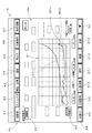
On the other hand, FIG. 2 shows a mold opening / closing screen Vm displayed on the
したがって、オペレータ(ユーザー)が型開閉画面切換キーK1を選択(ON)すれば、ディスプレイ4には、図2に示す型開閉画面Vmが表示される。この型開閉画面Vmは中間位置に、グラフ表示部61を有し、このグラフ表示部61には、図3(a)に示すトルクTに係わるグラフデータ、即ち、横軸を型閉時間tとしたトルク実測値TdのグラフデータDtd及びトルク制限値Tsc,TssのグラフデータDtc,Dts、又は図2及び図3(b)に示す型閉力Fに係わるグラフデータ、即ち、横軸を金型Cの型閉位置Xとした型閉力Fに係わるグラフデータDfd,Dfc,Dfsを選択的に表示することができる。
Therefore, when the operator (user) selects (ON) the mold opening / closing screen switching key K1, the
また、図2に示すように、型開閉画面Vmの左上には、金型保護モード切換キー62を有するとともに、型開閉画面Vmの左下には、表示切換キー63を有する。金型保護モード切換キー62は、「固定」モードと「高精度」モードに切換えるための切換キーである。この場合、「固定」モードは、固定(一定)のトルク制限値Tscを手動で設定するモードである。したがって、ユーザーは、不図示の設定画面により任意のトルク制限値Tscを数値により設定することができる。一方、「高精度」モードは、所定の条件に対応して変動するトルク制限値Tssが自動で設定されるモードであり、このトルク制限値Tssの設定は次のように行われる。
Further, as shown in FIG. 2, a mold protection
最初に、試し成形によりトルク制限値Tssの初期設定を行う。この際、トルク制限は解除しておく。試し成形の開始によりサーボモータ2が作動し、可動盤21mは型開位置から高速で型閉方向へ前進移動する高速型閉が行われる。この場合、サーボ回路32により可動盤21mに対する速度制御及び位置制御が行われる。具体的には、コントローラ34からサーボ回路32の偏差演算部41に対して位置指令値が付与され、ロータリエンコーダ33の検出パルスに基づいて得られる位置検出値と比較されることにより位置偏差分が得られる。そして、この位置偏差分に基づいて位置のフィードバック制御が行われる。この際、位置偏差分は、位置ループゲイン設定部44,フィードフォワードゲイン設定部45及び加減速時間設定部46により補償される。また、加減速時間設定部46の出力は、偏差演算部42に付与され、速度変換器47の出力と比較されることにより速度偏差分が得られる。そして、この速度偏差分に基づいて速度のフィードバック制御が行われる。この際、速度偏差分は速度ループゲイン設定部48により補償される。
First, initial setting of the torque limit value Tss is performed by trial molding. At this time, the torque limit is released. The
可動盤21mが型閉方向へ前進移動し、予め設定した金型保護区間(監視区間)の開始点に達すれば、設定したサンプリング周期毎にトルクTを検出する。金型保護区間は、低圧型締(低速型閉)開始点から高圧型締開始点までの間を設定できる。トルクTは、速度ループゲイン設定部48から出力する速度制御信号Scを取込むことにより検出する。即ち、速度制御信号Scの大きさは、トルクTの大きさに対応するため、速度制御信号Scの電圧値をトルク検出値Tdoとして用いる。サンプリング周期毎に検出されるトルク検出値Tdo…は、コントローラ34を介してメモリ35のデータエリアに書き込まれる。このようなトルク検出値Tdoの検出処理は、金型保護区間が終了するまで、サンプリング周期毎に実行される。
When the
また、一回目のショット(成形サイクル)が終了したなら、次のショットを行い、同様にトルク検出値Tdo…の検出を行うとともに、トルク検出値Tdo…に対する同様の検出を、予め設定したショット回数N分だけ行う。ショット回数N分の検出が終了したなら、得られたトルク検出値Tdo…から、各ショットにおける同一サンプリング順位のトルク検出値Tdo…に対する平均値Aiを算出する。さらに、各ショットにおける同一サンプリング順位のトルク検出値Tdo…から最大値Awを選出する。最大値Awは、前後のサンプリング順位に対して設定した所定の範囲における複数のサンプリング順位の中の最も大きい最大値を選出する。 Further, when the first shot (molding cycle) is completed, the next shot is performed, the torque detection value Tdo... Is detected in the same manner, and the same detection for the torque detection value Tdo. Do only N minutes. When the detection for the number of shots N is completed, an average value Ai for the torque detection values Tdo... Of the same sampling order in each shot is calculated from the obtained torque detection values Tdo. Further, the maximum value Aw is selected from the detected torque values Tdo. As the maximum value Aw, the largest maximum value among a plurality of sampling orders in a predetermined range set for the preceding and succeeding sampling orders is selected.
そして、得られた平均値Aiと最大値Awから、各サンプリング順位毎のトルク制限値Tssを、
Tss=Qi+kq=〔{(Aw−Ai)×kp}+Ai〕+kq …(100)
の演算式により求める。この場合、Qiは基準値である。また、kp,kqは定数であり、kqは基準値Qiに対して所定の余裕度(オフセット)を設定するための定数、kpは、通常、「1〜2」の間の任意数に設定することができる。なお、平均値Aiの代わりに中央値Ajを用いることもできる。即ち、各ショットにおける同一サンプリング順位のトルク検出値Tdo…に対する最小値Asと最大値Awを求め、この最小値Asと最大値Awから中央値Ajを、Aj=(Aw−As)/2の演算式により求めるとともに、この中央値Ajと最大値Awから、各トルク制限値Tssを、
Tss=〔{(Aw−Aj)×kp}+Aj〕+kq …(101)
の演算式により求めることもできる。なお、定数kp,kqは、前述した定数kp,kqと同一値であってもよいし、必要に応じて異ならせてもよい。
Then, from the obtained average value Ai and maximum value Aw, a torque limit value Tss for each sampling order is obtained,
Tss = Qi + kq = [{(Aw−Ai) × kp} + Ai] + kq (100)
Obtained by the following equation. In this case, Qi is a reference value. Kp and kq are constants, kq is a constant for setting a predetermined margin (offset) with respect to the reference value Qi, and kp is normally set to an arbitrary number between “1 and 2”. be able to. The median value Aj can be used instead of the average value Ai. That is, the minimum value As and the maximum value Aw for the torque detection values Tdo of the same sampling order in each shot are obtained, and the median value Aj is calculated from the minimum value As and the maximum value Aw by Aj = (Aw−As) / 2 While calculating | requiring by Formula, from this median value Aj and maximum value Aw, each torque limiting value Tss is
Tss = [{(Aw−Aj) × kp} + Aj] + kq (101)
It can also obtain | require by the computing equation of. The constants kp and kq may be the same value as the constants kp and kq described above, or may be different as necessary.
一方、得られたトルク制限値Tss…は、対応する型閉時間tと対にしてメモリ35に自動設定される。以上のトルク制限値Tss…を求める一連の処理は、自動設定モードを選択することにより設定されたシーケンス動作により自動で実行される。また、監視区間における異物検出のための閾値Di…の設定もトルク制限値Tss…の初期設定と同様に行われる。
On the other hand, the obtained torque limit values Tss... Are automatically set in the
さらに、初期設定されたトルク制限値Tss…と閾値Di…は、生産稼働時において、所定の条件となるショット回数が予め設定した設定数Mに達する毎に、自動設定モードの起動により定期的に自動更新される。なお、これらの設定方法や更新方法については、特開2004−330528号公報で開示される設定方法及び更新方法を利用できる。 Further, the initially set torque limit values Tss and threshold values Di are periodically set by the activation of the automatic setting mode every time the number of shots that satisfy a predetermined condition reaches a preset number M during production operation. Automatically updated. As for these setting method and updating method, the setting method and updating method disclosed in JP-A-2004-330528 can be used.
また、上述したサンプリング結果から型締工程(型閉工程)における正常な型閉時の型閉時間tと型閉位置Xの関係をデータベース5として設定する。即ち、所定のサンプリング周期毎に、少なくとも型閉時間tと型閉位置Xが得られるため、得られた結果から、例えば、教示分(複数回)を連続して採取し、各サンプリング順位の型閉時間tと型閉位置Xの平均を計算してメモリ35にデータベース5として保存(登録)する。このデータベース5は、独立したデータベースであってもよいし、トルク制限値Tss…,閾値Di…及び最大値Aw…等のデータと一緒のデータベースであってもよい。なお、型閉位置Xは、型閉時における可動型Cmの位置である。
Further, the relationship between the mold closing time t and the mold closing position X at the time of normal mold closing in the mold clamping process (mold closing process) is set as the
このように、トルク制限値Tsc,Tssに、少なくとも手動で設定する固定のトルク制限値Tsc及び/又は所定の条件に対応して変動する自動で設定されるトルク制限値Tssを含ませれば、手動設定モードと自動設定モードの双方に対応可能となり、特に、手動設定モードでは、自動設定が行われないことに対する設定支援ツールとして利用できるとともに、自動設定モードでは、自動で設定されてしまうことに対する設定確認ツールとして利用できる利点がある。 As described above, if the torque limit values Tsc and Tss include at least the fixed torque limit value Tsc that is manually set and / or the torque limit value Tss that is automatically set and fluctuates according to a predetermined condition, Both the setting mode and the automatic setting mode can be supported. Especially, in the manual setting mode, it can be used as a setting support tool for the fact that automatic setting is not performed, and in the automatic setting mode, it can be set for automatic setting. There is an advantage that can be used as a confirmation tool.
次に、本実施形態に係る成形機のデータ表示方法について、図1〜図7を参照して説明する。 Next, a data display method of the molding machine according to the present embodiment will be described with reference to FIGS.
最初に、本実施形態に係るデータ表示方法の理解を容易にするため、生産稼働時における型締工程の動作について説明する。型締工程では、サーボモータ2が作動し、まず、可動盤21mが型開位置から型閉方向へ高速で前進移動する高速型閉が行われる。この際、サーボ回路32により可動盤21mに対する速度制御及び位置制御が行われる。
First, in order to facilitate understanding of the data display method according to the present embodiment, the operation of the mold clamping process during production operation will be described. In the mold clamping process, the
そして、可動盤21mが型閉方向へ移動し、金型保護区間(監視区間)の開始点である低圧型締(低速型閉)開始点に達すれば、所定のサンプリング周期毎にトルクTの検出が行われ、トルク実測値Td…としてメモリ35のデータエリアに書き込まれる。したがって、これらの処理は、前述したトルク制限値Tssを初期設定する場合と同様に行われる。また、検出されたトルク実測値Td…は、トルク微分器51にも付与され、このトルク微分器51により微分されるとともに、微分後の微分検出値Ddはトルク微分比較処理部52に付与される。トルク微分比較処理部52には、コントローラ34から微分検出値Ddと同じサンプリング順位における設定された閾値Diが付与され、同じサンプリング順位の閾値Diと微分検出値Ddが比較処理される。したがって、可動型Cmと固定型Cc間に異物が挟まった場合には、異物を挟んだ時点でトルクが急上昇、即ち、速度制御信号Sc、更にはトルク微分器51から得られる微分検出値Ddも急激に大きくなるため、微分検出値Ddは閾値Diを越える。これにより、トルク微分比較処理部52は、異物が挟まったものとして検出し、サーボ回路32からコントローラ34に異物検出信号Seを付与する。これに対して、異物が挟まることなく正常な動作を継続すれば、微分検出値Ddは閾値Diを越えることが無いため、設定したサンプリング期間毎に、微分検出値Ddの検出処理がそのまま繰り返される。
When the
他方、サンプリング周期毎に検出されたトルク実測値Tdは、トルク比較処理部50にも付与される。トルク比較処理部50には、コントローラ34からトルク実測値Tdと同じサンプリング順位のトルク制限値Tsが付与されており、同じサンプリング順位におけるトルク制限値Tsとトルク実測値Tdが比較処理される。そして、トルク実測値Tdが増加し、トルク制限値Tsに達した場合には、トルク制限値Tsを越えないように、コントローラ34及びサーボ回路32によるトルク制御処理が行われる。さらに、監視区間の終了により、可動盤21mが低圧型締の終了する低圧終了位置、即ち、高圧型締開始位置に達すれば、高圧制御による高圧型締が行われ、さらに、所定の成形動作が終了すれば、型開きが行われる。
On the other hand, the actual torque value Td detected for each sampling period is also given to the torque
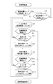
次に、本実施形態に係る成形機のデータ表示方法について、各図を参照しつつ図1に示すフローチャートに従って説明する。 Next, the data display method of the molding machine according to the present embodiment will be described according to the flowchart shown in FIG. 1 with reference to the drawings.
金型保護モード切換キー62は、「高精度」モードに切換えられているものとする(ステップS1)。なお、金型保護モード切換キー62は、「固定」モードに切換えることもできる(ステップS2)。「固定」モードは、ユーザーが手動で設定するモードであるため、「固定」モードを選択した場合には、設定した数値により固定(一定)されたトルク制限値Tscが機能する。
It is assumed that the mold protection
また、表示切換キー63は操作しない限り、標準となる「トルク」表示モードに切換わっている。これにより、少なくとも型締工程(型閉工程)の金型保護区間では、図3(a)に示すように、横軸を型閉時間tとしたトルク実測値Td…をグラフデータDtdとして型開閉画面Vmのグラフ表示部61に表示する。また、メモリ35からは予め設定したトルク制限値Tss…を読出し、トルク制限値Tss…のグラフデータDtsを、トルク実測値Td…の型閉時間tに同期させてグラフ表示部61に表示する(ステップS3)。トルク制限値Tscは、ユーザーが設定した一定値のため、グラフ表示部61には一本の直線によるグラフデータDtcが水平に表示される。このようなトルクTに係わるグラフ表示部61におけるグラフデータDtd…の表示は、型開閉画面切換キーK1の選択を解除しない限り継続する(ステップS4)。
The
このように、トルクTに係わるグラフデータDtd,Dtc,Dtsに、少なくともトルク実測値Tdに係わるグラフデータDtd、及び/又はトルク制限値Tsc,Tssに係わるグラフデータDtc,Dtsを含ませれば、実際に発生する型閉力Fの大きさとトルク制限値Tsc,Tssに対応する型閉力Fの大きさを同時に把握できるため、過大な型閉力Fに対してもどの程度の水準にあるのかなどを容易かつ的確に把握できる利点がある。 As described above, if the graph data Dtd, Dtc, and Dts related to the torque T include at least the graph data Dtd related to the actually measured torque value Td and / or the graph data Dtc and Dts related to the torque limit values Tsc and Tss, Since the magnitude of the mold closing force F generated at the same time and the magnitude of the mold closing force F corresponding to the torque limit values Tsc, Tss can be grasped at the same time, what level is there for the excessive mold closing force F, etc. There is an advantage that can be grasped easily and accurately.
ところで、このようなトルクTに係わるグラフデータDtd,Dtc,Dtsの表示では、トグルリンク機構3の場合、金型Cにおける実際の型閉力Fを把握できない。このため、例えば、直圧式型締装置を搭載する射出成形機のユーザーが、トグルリンク式型締装置Mcを搭載した新規の射出成形機Mを導入したような場合、直圧式型締装置を使用していた際における異物の有無を監視するトルク制限値(閾値)及び監視条件等の設定に係わるノウハウや感覚(勘)を利用できなくなる。結局、設定作業が面倒かつ設定時間が長時間化し、作業能率の低下を来すのみならず、反って不適切な設定或いは誤設定を招く虞れもあるなど、より確実な金型保護を図る観点からは好ましくない。
By the way, in the case of the
そこで、ユーザーは、トルクTに係わるグラフデータDtd,Dtc,Dtsの表示を、型閉力Fに係わるグラフデータDfd,Dfc,Dfsの表示に変更することができる(ステップS5)。この場合、ユーザーは、表示切換キー63を操作し、「トルク」表示モードを「型閉力」表示モードに切換える(ステップS6)。これにより、図2及び図3(b)に示すように、型閉力Fに係わるグラフデータDfd,Dfc,Dfsが切換表示される(ステップS7)。 Therefore, the user can change the display of the graph data Dtd, Dtc, Dts related to the torque T to the display of the graph data Dfd, Dfc, Dfs related to the mold closing force F (step S5). In this case, the user operates the display switching key 63 to switch the “torque” display mode to the “mold closing force” display mode (step S6). Thereby, as shown in FIG. 2 and FIG. 3B, the graph data Dfd, Dfc, and Dfs related to the mold closing force F are switched and displayed (step S7).
この場合、所定のサンプリング間隔毎に、トルクTから金型Cの型閉力Fを求め、かつ型閉力Fを求めたトルクTの検出時における金型Cの型閉位置Xを求める。具体的には、予め設定した所定の演算式により求めることができ、演算式には、
F={(2πRTη)/Np}・k(x) …(102)
を用いることができる。なお、この演算式において、Rは減速比,Tはトルク〔Nmm〕,ηは機械効率,Npはボールねじのピッチ〔mm〕,k(x)は型閉位置Xにより変化する係数である。
In this case, the mold closing force F of the mold C is obtained from the torque T at every predetermined sampling interval, and the mold closing position X of the mold C at the time of detecting the torque T obtained from the mold closing force F is obtained. Specifically, it can be obtained by a predetermined arithmetic expression set in advance,
F = {(2πRTη) / Np} · k (x) (102)
Can be used. In this equation, R is the reduction ratio, T is the torque [Nmm], η is the mechanical efficiency, Np is the pitch of the ball screw [mm], and k (x) is a coefficient that varies depending on the mold closing position X.
そして、手動で設定する固定のトルク制限値Tscを型閉力Fに係わるグラフデータDfcに変換する場合には、この演算式の機械効率ηを「0.5」前後に設定できる。また、トルク実測値Tdを型閉力Fに係わるグラフデータDfdに変換する場合、及び自動で設定されるトルク制限値Tssを型閉力Fに係わるグラフデータDfsに変換する場合には、この演算式の機械効率ηを「0.9」前後に設定できる。このように、トルクTに係わるグラフデータDtd,Dtc,Dtsから金型Cにおける型閉力Fに係わるグラフデータDfd,Dfc,Dfsへの変換に、予め設定した所定の演算式(102)を用いれば、正確で信頼性の高い型閉力Fを容易に求めることができる。 When the manually set fixed torque limit value Tsc is converted into the graph data Dfc related to the mold closing force F, the mechanical efficiency η of this arithmetic expression can be set to around “0.5”. Further, when converting the actually measured torque value Td into the graph data Dfd related to the mold closing force F, and when converting the automatically set torque limit value Tss to the graph data Dfs related to the mold closing force F, this calculation is performed. The mechanical efficiency η in the equation can be set around “0.9”. As described above, a predetermined arithmetic expression (102) set in advance is used to convert the graph data Dtd, Dtc, Dts related to the torque T to the graph data Dfd, Dfc, Dfs related to the mold closing force F in the mold C. Thus, an accurate and reliable mold closing force F can be easily obtained.
また、型閉位置Xは、予め設定した、正常な型閉時における型閉時間tと型閉位置Xの関係を登録したデータベース5から求める。即ち、トルクTを検出した型閉時間tに対応する型閉位置Xをデータベース5から読出す。このように、型閉位置Xを、正常な型閉時における型閉時間tと型閉位置Xの関係を登録したデータベース5から求めるようにすれば、位置センサによる位置検出が不要になるとともに、型閉時間tを型閉位置Xに反映できるため、より多様性のある表示を行うことができる。
The mold closing position X is obtained from the
このような処理を経ることにより、型閉力Fに係わるグラフデータDfd,Dfc,Dfsが、図2及び図3(b)に示すグラフ表示部61に表示される。このグラフ表示部61におけるグラフデータDfd,Dfc,Dfsの表示は、型開閉画面切換キーK1の選択を解除しない限り継続する(ステップS8)。他方、ユーザーは、このような「型閉力」表示モードを、標準となる「トルク」表示モードに復帰させることができる(ステップS9)。この場合、表示切換キー63を操作し、「型閉力」表示モードを「トルク」表示モードに切換える(ステップS10)。これにより、トルクTに係わるグラフデータDtd…がグラフ表示部61に切換表示される(ステップS3…)。
Through such processing, graph data Dfd, Dfc, and Dfs related to the mold closing force F are displayed on the
なお、図2及び図3(b)には、型閉力Fに係わるグラフデータDfd,Dfc,Dfsを表示した態様を示したが、図4に示すように、グラフデータDfcを除いたグラフデータDfd及びDfsを表示してもよい。これにより、Y軸方向のレンジを小さくできるため、変化度合をより強調して表示することができる。したがって、このような表示態様は、例示に限定されることなく各種態様を適用できる。 FIGS. 2 and 3B show a mode in which the graph data Dfd, Dfc, and Dfs related to the mold closing force F are displayed. As shown in FIG. 4, the graph data excluding the graph data Dfc is shown. Dfd and Dfs may be displayed. Thereby, since the range in the Y-axis direction can be reduced, the degree of change can be displayed with more emphasis. Therefore, such a display mode is not limited to an example, and various modes can be applied.
よって、このような本実施形態に係るデータ表示方法によれば、トルクTに係わるグラフデータDtd,Dtc,Dtsを金型Cにおける型閉力Fに係わるグラフデータDfd,Dfc,Dfsに変換し、かつトルクTの検出時における金型Cの型閉位置Xを求めるとともに、型閉位置Xに対する型閉力Fに係わるグラフデータDfd,Dfc,Dfsを、トルクTに係わるグラフデータDtd,Dtc,Dtsの表示に代えて、又はトルクTに係わるグラフデータDtd,Dtc,Dtsの表示に加えて、ディスプレイ4に表示するようにしたため、トグルリンク式型締装置Mcであっても、金型Cにおける実際の型閉力Fの大きさを容易かつ正確に把握できる。したがって、各種設定作業の容易化及び迅速化による作業能率向上に寄与できるとともに、より確実な金型保護を実現できる。特に、直圧式型締装置からトグルリンク式型締装置に変更したような場合でも、ユーザーは異物の有無を監視する際のトルク制限値や閾値及び監視条件等の設定を容易かつ的確に行うことができる。
Therefore, according to such a data display method according to the present embodiment, the graph data Dtd, Dtc, Dts related to the torque T are converted into the graph data Dfd, Dfc, Dfs related to the mold closing force F in the mold C, In addition, the mold closing position X of the mold C at the time of detecting the torque T is obtained, and the graph data Dfd, Dfc, and Dfs related to the mold closing force F with respect to the mold closing position X are converted into the graph data Dtd, Dtc, Dts related to the torque T. Or in addition to the display of graph data Dtd, Dtc, and Dts related to torque T, the
以上、最良の実施形態について詳細に説明したが、本発明は、このような実施形態に限定されるものではなく、細部の構成,形状,素材,数量,数値等において、本発明の要旨を逸脱しない範囲で、任意に変更,追加,削除することができる。 Although the best embodiment has been described in detail above, the present invention is not limited to such an embodiment, and departs from the gist of the present invention in the detailed configuration, shape, material, quantity, numerical value, and the like. It can be changed, added, or deleted as long as it is not.
例えば、例示の演算式は必要により他の演算式に置換することができ、例示の演算式に限定されるものではない。また、この演算式には、データベース(データテーブル)を利用して変換する場合も含まれる。したがって、実施形態で挙げたデータベース5も、このデータベースの代わりに演算式で求める場合が含まれる。一方、サーボモータ2を例示したが、他の種類のモータを排除するものではない。さらに、実施形態では、型閉位置Xに対する型閉力Fに係わるグラフデータDfd…を、トルクTに係わるグラフデータDtd…に代えて表示する場合を例示したが、トルクTに係わるグラフデータDtd…に加えて表示してもよい。この場合、加えて表示するとは、一つのグラフ表示部61の中に重畳して表示する態様と二つのグラフ表示部61…を二段表示する態様が含まれる。また、トルクTに係わるグラフデータDtd,Dtc,Dtsとして、トルク実測値Tdに係わるグラフデータDtdとトルク制限値Tsc,Tssに係わるグラフデータDtc,Dtsを挙げたが、トルク指令値に係わるグラフデータを含ませてもよい。これにより、実際に発生する型閉力Fの大きさとトルク指令値に対応する型閉力Fの大きさを同時に把握することができる。なお、本発明に係るデータ表示方法は、例示の射出成形機Mをはじめ、トグルリンク式型締装置を搭載した他の各種成形機(押出成形機等)にも同様に利用することができる。
For example, the exemplary arithmetic expression can be replaced with another arithmetic expression as necessary, and is not limited to the exemplary arithmetic expression. In addition, this arithmetic expression includes a case where conversion is performed using a database (data table). Therefore, the
2:モータ,3:トグルリンク機構,4:ディスプレイ,5:データベース,C:金型,Mc:型締装置,Dtd:グラフデータ,Dtc:グラフデータ,Dts:グラフデータ,Dfd:グラフデータ,Dfc:グラフデータ,Dfs:グラフデータ 2: motor, 3: toggle link mechanism, 4: display, 5: database, C: mold, Mc: clamping device, Dtd: graph data, Dtc: graph data, Dts: graph data, Dfd: graph data, Dfc : Graph data, Dfs: Graph data
Claims (2)
Priority Applications (1)
| Application Number | Priority Date | Filing Date | Title |
|---|---|---|---|
| JP2007178520A JP4982273B2 (en) | 2007-07-06 | 2007-07-06 | Data display method of molding machine |
Applications Claiming Priority (1)
| Application Number | Priority Date | Filing Date | Title |
|---|---|---|---|
| JP2007178520A JP4982273B2 (en) | 2007-07-06 | 2007-07-06 | Data display method of molding machine |
Publications (2)
| Publication Number | Publication Date |
|---|---|
| JP2009012380A JP2009012380A (en) | 2009-01-22 |
| JP4982273B2 true JP4982273B2 (en) | 2012-07-25 |
Family
ID=40353864
Family Applications (1)
| Application Number | Title | Priority Date | Filing Date |
|---|---|---|---|
| JP2007178520A Active JP4982273B2 (en) | 2007-07-06 | 2007-07-06 | Data display method of molding machine |
Country Status (1)
| Country | Link |
|---|---|
| JP (1) | JP4982273B2 (en) |
Families Citing this family (2)
| Publication number | Priority date | Publication date | Assignee | Title |
|---|---|---|---|---|
| JP6042451B2 (en) * | 2012-11-13 | 2016-12-14 | 東洋機械金属株式会社 | Abnormality monitoring method for injection molding machines |
| JP6158718B2 (en) * | 2014-01-17 | 2017-07-05 | 株式会社ソディック | Automatic mold protection setting value calculation method for injection molding machines |
Family Cites Families (6)
| Publication number | Priority date | Publication date | Assignee | Title |
|---|---|---|---|---|
| JPH05293863A (en) * | 1992-04-22 | 1993-11-09 | Japan Steel Works Ltd:The | Mold clamping force measuring method for toggle type mold clamping machine |
| JPH10305463A (en) * | 1997-05-01 | 1998-11-17 | Toyo Mach & Metal Co Ltd | Molding machine |
| JP3648059B2 (en) * | 1998-06-25 | 2005-05-18 | 東洋機械金属株式会社 | Molding machine |
| JP3795323B2 (en) * | 2000-12-05 | 2006-07-12 | 日精樹脂工業株式会社 | Foreign matter detection method for injection molding machine |
| JP3894903B2 (en) * | 2003-05-02 | 2007-03-22 | 日精樹脂工業株式会社 | Mold clamping control method of injection molding machine |
| JP4146381B2 (en) * | 2004-03-31 | 2008-09-10 | 日精樹脂工業株式会社 | Clamping force correction method for toggle type mold clamping device |
-
2007
- 2007-07-06 JP JP2007178520A patent/JP4982273B2/en active Active
Also Published As
| Publication number | Publication date |
|---|---|
| JP2009012380A (en) | 2009-01-22 |
Similar Documents
| Publication | Publication Date | Title |
|---|---|---|
| US6526360B1 (en) | Power consumption display device for machine | |
| US6904819B2 (en) | Monitor for injection molding machine | |
| JP3795323B2 (en) | Foreign matter detection method for injection molding machine | |
| JPH0649314B2 (en) | Data processing method of injection molding machine | |
| JPH0358821A (en) | Injection pressure control method for motorized injection molding machine | |
| CN100496942C (en) | Mold clamping force correction method for mold clamping apparatus | |
| EP0396770B1 (en) | Back pressure control method and apparatus for electric injection molding machine | |
| CN100515725C (en) | Controllers for injection molding machines | |
| JP4982273B2 (en) | Data display method of molding machine | |
| WO2022085580A1 (en) | Molding-condition-setting device and molding-condition-setting method | |
| JP2545465B2 (en) | Method for automatically setting upper and lower limits of molding conditions of molding machine | |
| JPS63130326A (en) | Molding condition setting equipment for injection molding machine | |
| JP2001277319A (en) | Molding characteristic determination method and injection molding machine | |
| JPS6378722A (en) | Detector of mold touching position in motor-driven direct pressure type mold clamping mechanism | |
| JP4263661B2 (en) | Monitoring display method of molding machine | |
| JP3962355B2 (en) | Mold clamping control method of injection molding machine | |
| JP3820232B2 (en) | Mold clamping control method of injection molding machine | |
| JP3881633B2 (en) | Mold clamping control method of injection molding machine | |
| JP3894904B2 (en) | Mold clamping control method of injection molding machine | |
| JP4146383B2 (en) | Mold protection method for mold clamping device | |
| JPH068020B2 (en) | Automatic mold touch position setting device for toggle type mold clamping device | |
| JPH07299849A (en) | In-mold pressure measuring method | |
| JPH06210692A (en) | Molding machine with product schedule monitoring function | |
| JPH09174637A (en) | Injection molding machine and its measuring condition setting method | |
| JP4474368B2 (en) | Data processing method and apparatus for molding machine |
Legal Events
| Date | Code | Title | Description |
|---|---|---|---|
| A621 | Written request for application examination |
Free format text: JAPANESE INTERMEDIATE CODE: A621 Effective date: 20081211 |
|
| A977 | Report on retrieval |
Free format text: JAPANESE INTERMEDIATE CODE: A971007 Effective date: 20110726 |
|
| A131 | Notification of reasons for refusal |
Free format text: JAPANESE INTERMEDIATE CODE: A131 Effective date: 20110803 |
|
| A521 | Request for written amendment filed |
Free format text: JAPANESE INTERMEDIATE CODE: A523 Effective date: 20110928 |
|
| TRDD | Decision of grant or rejection written | ||
| A01 | Written decision to grant a patent or to grant a registration (utility model) |
Free format text: JAPANESE INTERMEDIATE CODE: A01 Effective date: 20120404 |
|
| A01 | Written decision to grant a patent or to grant a registration (utility model) |
Free format text: JAPANESE INTERMEDIATE CODE: A01 |
|
| A61 | First payment of annual fees (during grant procedure) |
Free format text: JAPANESE INTERMEDIATE CODE: A61 Effective date: 20120423 |
|
| FPAY | Renewal fee payment (event date is renewal date of database) |
Free format text: PAYMENT UNTIL: 20150427 Year of fee payment: 3 |
|
| R150 | Certificate of patent or registration of utility model |
Ref document number: 4982273 Country of ref document: JP Free format text: JAPANESE INTERMEDIATE CODE: R150 Free format text: JAPANESE INTERMEDIATE CODE: R150 |
|
| R250 | Receipt of annual fees |
Free format text: JAPANESE INTERMEDIATE CODE: R250 |
|
| R250 | Receipt of annual fees |
Free format text: JAPANESE INTERMEDIATE CODE: R250 |
|
| R250 | Receipt of annual fees |
Free format text: JAPANESE INTERMEDIATE CODE: R250 |
|
| R250 | Receipt of annual fees |
Free format text: JAPANESE INTERMEDIATE CODE: R250 |
|
| R250 | Receipt of annual fees |
Free format text: JAPANESE INTERMEDIATE CODE: R250 |