JP4986748B2 - Multi-layer flow path member of ultrasonic fluid measuring device - Google Patents
Multi-layer flow path member of ultrasonic fluid measuring device Download PDFInfo
- Publication number
- JP4986748B2 JP4986748B2 JP2007179952A JP2007179952A JP4986748B2 JP 4986748 B2 JP4986748 B2 JP 4986748B2 JP 2007179952 A JP2007179952 A JP 2007179952A JP 2007179952 A JP2007179952 A JP 2007179952A JP 4986748 B2 JP4986748 B2 JP 4986748B2
- Authority
- JP
- Japan
- Prior art keywords
- partition
- flow path
- partition plate
- support portion
- path member
- Prior art date
- Legal status (The legal status is an assumption and is not a legal conclusion. Google has not performed a legal analysis and makes no representation as to the accuracy of the status listed.)
- Expired - Fee Related
Links
Images


Landscapes
- Measuring Volume Flow (AREA)
Description
本発明は、超音波式流体計測装置に形成された角筒状の計測流路に配置され、この計測流路を複数の扁平流路に区画する仕切板を有する超音波式流体計測装置の多層流路部材に関するものである。 The present invention relates to a multilayer of an ultrasonic fluid measurement device having a partition plate arranged in a rectangular tube-shaped measurement flow channel formed in an ultrasonic fluid measurement device and partitioning the measurement flow channel into a plurality of flat flow channels. The present invention relates to a flow path member.
超音波式流体計測装置は、計測用流路に流体を流し、計測用流路内に超音波を伝搬させて、超音波の伝搬時間を計測し、計測した情報に基づいて流体の流速を求めるものである。
この計測用流路は、断面長方形の角筒形状で対向する短辺側面にそれぞれ一対の送受波部が設けられている。
The ultrasonic fluid measurement device flows a fluid through a measurement channel, propagates the ultrasonic wave in the measurement channel, measures the propagation time of the ultrasonic wave, and obtains the flow velocity of the fluid based on the measured information. Is.
This measurement channel has a rectangular tube shape with a rectangular cross section, and a pair of transmission / reception units are provided on the opposing short side surfaces.
これら一対の送受波部は、計測用流路の流れ方向に対して所定の角度で交差する線に沿って超音波を送受するように配置されている。
そして、近年では、計測精度を向上させるために、計測用流路に複数の隔壁を並行に配置することにより、計測用流路を多層流路とした超音波式流体計測装置が提案されている(例えば、特許文献1参照)。
In recent years, in order to improve the measurement accuracy, an ultrasonic fluid measuring apparatus in which a plurality of partition walls are arranged in parallel in the measurement flow path and the measurement flow path is a multilayer flow path has been proposed. (For example, refer to Patent Document 1).
しかしながら、前述した特許文献1に記載の超音波式流体計測装置において多層流路を形成する仕切板は予め決められた位置に一体的に設けられているので、多層流路の積層数や間隔の調整が困難であり、汎用性がなかった。また、汎用性がないため、コストが高くなるという問題があった。 However, in the ultrasonic fluid measuring device described in Patent Document 1 described above, the partition plate that forms the multilayer flow path is integrally provided at a predetermined position. Adjustment was difficult and there was no versatility. Moreover, since there was no versatility, there existed a problem that cost became high.
本発明は、従来の問題を解決するためになされたもので、汎用性を持たせて、コストの低減を図ることのできる超音波式流体計測装置の多層流路部材を提供することを目的とする。 An object of the present invention is to provide a multilayer flow path member of an ultrasonic fluid measuring device that has been made in order to solve the conventional problems and can be versatile and can reduce costs. To do.
本発明の超音波式流体計測装置の多層流路部材は、超音波式流体計測装置に形成された角筒状の計測流路に配置され、前記計測流路を複数の扁平流路に区画する仕切板を有する超音波式流体計測装置の多層流路部材であって、前記仕切板における流体の流れ方向に沿った縁部を支持するとともに、前記仕切板の厚み方向に立ち上がる支持部とを備える区画部材を有し、前記区画部材を複数積層させることにより形成されている構成を有している。 The multilayer flow path member of the ultrasonic fluid measurement device of the present invention is disposed in a rectangular tube-shaped measurement flow channel formed in the ultrasonic fluid measurement device, and divides the measurement flow channel into a plurality of flat flow channels. A multilayer flow path member of an ultrasonic fluid measuring device having a partition plate, comprising: a support portion that supports an edge portion in a fluid flow direction of the partition plate and rises in a thickness direction of the partition plate. It has a structure which has a partition member and is formed by laminating | stacking the said partition member in multiple numbers.
この構成により、超音波式流体計測装置に形成された角筒状の計測流路を扁平流路に区画する仕切板を設ける際に、仕切板の縁部を支持するとともに仕切板の厚み方向に高さを有する区画部材を配置したので、仕切板を所定の間隔で保持することができる。また、区画部材の高さによって仕切板の間隔を決定するので、仕切板の間隔を調整して、扁平流路の高さを調整することができる。このため、汎用性に富み、コストの低減化を図ることができる。 With this configuration, when providing a partition plate that divides the rectangular tubular measurement channel formed in the ultrasonic fluid measurement device into a flat channel, the edge of the partition plate is supported and the thickness of the partition plate is increased. Since the partition member having the height is arranged, the partition plate can be held at a predetermined interval. Moreover, since the space | interval of a partition plate is determined by the height of a partition member, the space | interval of a partition plate can be adjusted and the height of a flat flow path can be adjusted. For this reason, it is rich in versatility, and cost reduction can be achieved.
また、本発明の超音波式流体計測装置の多層流路部材は、前記区画部材が、前記仕切板と、前記仕切板を厚み方向に挟持する角柱状の支持部とを有する構成を有している。 Moreover, the multilayer flow path member of the ultrasonic fluid measuring device of the present invention has a configuration in which the partition member includes the partition plate and a prismatic support portion that sandwiches the partition plate in the thickness direction. Yes.
この構成により、仕切板は、仕切板を厚み方向に挟持する区画部材の角柱状の支持部によって支持されるので、支持部の高さの調整により、仕切板を所望の高さに調整することができる。 With this configuration, since the partition plate is supported by the prismatic support portion of the partition member that sandwiches the partition plate in the thickness direction, the partition plate is adjusted to a desired height by adjusting the height of the support portion. Can do.
さらに、本発明の超音波式流体計測装置の多層流路部材は、前記区画部材が、前記仕切板と、前記仕切板の片面に取り付けられた角柱状の支持部とを有する構成を有している。 Furthermore, the multilayer flow path member of the ultrasonic fluid measuring device according to the present invention has a configuration in which the partition member includes the partition plate and a prismatic support portion attached to one surface of the partition plate. Yes.
この構成により、仕切板は、仕切板の片面に取り付けられた区画部材の角柱状の支持部によって支持されるので、支持部の高さの調整により、仕切板を所望の高さに調整することができる。 With this configuration, since the partition plate is supported by the prismatic support portion of the partition member attached to one side of the partition plate, the partition plate is adjusted to a desired height by adjusting the height of the support portion. Can do.
さらに、本発明の超音波式流体計測装置の多層流路部材は、前記区画部材が、前記仕切板と、前記仕切板の両縁部全域に設けられた折曲部と、前記各折曲部の所定位置に設けられて超音波を透過するフィルタ部材と、前記仕切板の片面に取り付けられるとともに前記折曲部に沿う角柱状の支持部とを有する構成を有している。 Furthermore, in the multilayer flow path member of the ultrasonic fluid measuring device of the present invention, the partition member is the partition plate, a bent portion provided in the entire area of both edges of the partition plate, and each bent portion. And a filter member that transmits ultrasonic waves, and a prismatic support portion that is attached to one surface of the partition plate and extends along the bent portion.
この構成により、区画部材は、仕切板の両縁の全体に設けられている折曲部に沿って設けられる各柱状の支持部を介して所定間隔で積層されて、多層の扁平流路を形成する。そして、折曲部の所定位置に設けたフィルタ部材を透過して超音波が発せられて、流体の速度を検出する。 With this configuration, the partition members are stacked at predetermined intervals via the columnar support portions provided along the bent portions provided on the entire edges of the partition plate to form a multi-layered flat flow path. To do. Then, an ultrasonic wave is transmitted through the filter member provided at a predetermined position of the bent portion, and the velocity of the fluid is detected.
また、本発明の超音波式流体計測装置の多層流路部材は、前記区画部材が、前記仕切板と、前記仕切板の両縁部の所定位置に設けられた折曲部と、前記各折曲部に設けられて超音波を透過するフィルタ部材と、前記仕切板の片面に取り付けられるとともに前記折曲部に沿う角柱状の支持部とを有し、前記折曲部の内面と前記支持部の内面とが同一平面に沿う構成を有している。 Further, in the multilayer flow path member of the ultrasonic fluid measuring device of the present invention, the partition member includes the partition plate, a bent portion provided at a predetermined position of both edge portions of the partition plate, and each of the folds. A filter member that is provided in the bent portion and transmits ultrasonic waves; and a prismatic support portion that is attached to one side of the partition plate and extends along the bent portion, and the inner surface of the bent portion and the support portion And the inner surface of the same has a configuration along the same plane.
この構成により、区画部材は、仕切板の両縁の所定位置に設けられている折曲部に沿って設けられる各柱状の支持部を介して所定間隔で積層されて、多層の扁平流路を形成する。そして、折曲部に設けたフィルタ部材を透過して超音波が発せられて、流体の速度を検出する。 With this configuration, the partition members are stacked at predetermined intervals via the columnar support portions provided along the bent portions provided at predetermined positions on both edges of the partition plate, and the multi-layer flat flow path is formed. Form. Then, an ultrasonic wave is transmitted through the filter member provided in the bent portion, and the velocity of the fluid is detected.
さらに、本発明の超音波式流体計測装置の多層流路部材は、前記支持部が、前記仕切板の両縁部を折り曲げることにより形成されている構成を有している。 Furthermore, the multilayer flow path member of the ultrasonic fluid measuring device of the present invention has a configuration in which the support portion is formed by bending both edge portions of the partition plate.
この構成により、区画部材は、仕切板の両縁部を折り曲げて形成した支持部を介して、所定間隔で積層されて多層の扁平流路を形成する。 With this configuration, the partition member is laminated at a predetermined interval via a support portion formed by bending both edge portions of the partition plate to form a multilayer flat flow path.
さらに、本発明の超音波式流体計測装置の多層流路部材は、前記区画部材が、複数の前記仕切板と、前記各仕切板間を連結する壁部とを一体成型することにより扁平角筒状に形成されている構成を有している。 Furthermore, in the multilayer flow path member of the ultrasonic fluid measuring device according to the present invention, the partition member is formed by integrally molding a plurality of the partition plates and a wall portion connecting the partition plates. It has the structure currently formed in the shape.
この構成により、区画部材は、一体成型によって、複数枚の仕切板を壁部によって所定間隔で連結した扁平角筒状に形成されているので、この区画部材を積層することにより、扁平流路を有する多層流路部材を形成することができる。 With this configuration, the partition member is formed into a flat rectangular tube shape in which a plurality of partition plates are connected at a predetermined interval by a wall portion by integral molding, so that the flat channel is formed by stacking the partition members. A multilayer flow path member can be formed.
また、本発明の超音波式流体計測装置の多層流路部材は、前記区画部材が、複数の前記仕切板と、前記各仕切板間を連結する壁部とを一体成型することにより略コ字状に形成されている構成を有している。 Further, the multilayer flow path member of the ultrasonic fluid measuring device of the present invention is configured such that the partition member is formed by integrally molding the plurality of partition plates and a wall portion connecting the partition plates. It has the structure currently formed in the shape.
この構成により、区画部材は、一体成型によって、複数枚の仕切板を壁部によって所定間隔で連結した略コ字状に形成されているので、この区画部材を積層することにより、扁平流路を有する多層流路部材を形成することができる。 With this configuration, the partition member is formed in a substantially U-shape by connecting a plurality of partition plates at a predetermined interval by a wall portion by integral molding, so that the flat flow path is formed by stacking the partition members. A multilayer flow path member can be formed.
さらに、本発明の超音波式流体計測装置の多層流路部材は、前記区画部材が、前記支持部を一括して貫通する連結ピンにより一体化されている構成を有している。 Furthermore, the multilayer flow path member of the ultrasonic fluid measuring device of the present invention has a configuration in which the partition member is integrated by a connecting pin that penetrates the support portion at once.
この構成により、積層された区画部材の支持部を、連結ピンが一括して貫通するので、各区画部材を確実に位置決めすることができる。 With this configuration, the connecting pins collectively penetrate the support portions of the stacked partition members, so that each partition member can be positioned reliably.
さらに、本発明の超音波式流体計測装置の多層流路部材は、前記支持部に設けられて超音波を透過させるフィルタ部材に撥水性処理が施されている構成を有している。 Furthermore, the multilayer flow path member of the ultrasonic fluid measuring device of the present invention has a configuration in which a water repellent treatment is performed on a filter member that is provided on the support and transmits ultrasonic waves.
この構成により、フィルタ部材に撥水性処理が施されているのでフィルタ部材に当たった流体ははじかれ、流体による目詰まりが生じにくいので、計測精度を向上させることができる。 With this configuration, since the water repellent treatment is applied to the filter member, the fluid hitting the filter member is repelled and clogging by the fluid is less likely to occur, so that the measurement accuracy can be improved.
そして、本発明の超音波式流体計測装置の多層流路部材は、前記区画部材が、前記支持部に設けられた接続ピンと、前記接続ピンを挿入する接続穴とにより一体化されている構成を有している。 And the multilayer flow path member of the ultrasonic fluid measuring device of the present invention has a configuration in which the partition member is integrated by a connection pin provided in the support portion and a connection hole into which the connection pin is inserted. Have.
この構成により、各区画部材を積層させた状態で固定するための連結ピンが不要となり、製造コストを低減できる。 With this configuration, a connecting pin for fixing the partition members in a stacked state is not necessary, and the manufacturing cost can be reduced.
また、本発明の超音波式流体計測装置の多層流路部材は、前記区画部材が、前記接続ピンと前記接続穴とのうちの少なくとも一方がテーパ形状である構成を有している。 In the multilayer flow path member of the ultrasonic fluid measurement device of the present invention, the partition member has a configuration in which at least one of the connection pin and the connection hole is tapered.
この構成により、接続ピンの外面および接続穴の内面のうちの一方がテーパ面であるため、接続ピンの外面および接続穴の内面のうちの他方がテーパ面に対して線接触し、これにより各区画部材を積層させた状態で接続ピンおよび接続穴の寸法公差による各区画部材のガタが生じない。 With this configuration, since one of the outer surface of the connection pin and the inner surface of the connection hole is a tapered surface, the other of the outer surface of the connection pin and the inner surface of the connection hole is in line contact with the tapered surface. In the state where the partition members are stacked, the play of the partition members due to the dimensional tolerances of the connection pins and the connection holes does not occur.
本発明は、超音波式流体計測装置に形成された角筒状の計測流路を扁平流路に区画する仕切板を設ける際に、仕切板の縁部を支持するとともに仕切板の厚み方向に高さを有する区画部材を配置したので、仕切板を所定の間隔で保持することができる。また、区画部材の高さによって仕切板の間隔を決定するので、仕切板の間隔を調整して、扁平流路の高さを調整することができる。このため、汎用性に富み、コストの低減化を図ることができるという効果を有する超音波式流体計測装置の多層流路部材を提供することができるものである。 The present invention supports the edge of the partition plate and provides it in the thickness direction of the partition plate when providing the partition plate that partitions the rectangular tubular measurement channel formed in the ultrasonic fluid measurement device into a flat channel. Since the partition member having the height is arranged, the partition plate can be held at a predetermined interval. Moreover, since the space | interval of a partition plate is determined by the height of a partition member, the space | interval of a partition plate can be adjusted and the height of a flat flow path can be adjusted. For this reason, it is rich in versatility and can provide the multilayer flow path member of the ultrasonic fluid measuring device having the effect of being able to reduce the cost.
(第1実施形態)
以下、本発明の第1実施形態にかかる超音波式流体計測装置の多層流路部材について、図面を用いて説明する。
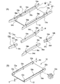
図1は本発明の第1実施形態にかかる超音波式流体計測装置の多層流路部材を用いることができる超音波式流体計測装置を示す分解斜視図、図2は本発明の第1実施形態にかかる超音波式流体計測装置の多層流路部材を構成する区画部材の分解斜視図、図3は区画部材を積層して多層流路部材を形成する状態を示す斜視図、図4は多層流路部材の正面図である。
(First embodiment)
Hereinafter, the multilayer flow path member of the ultrasonic fluid measuring apparatus according to the first embodiment of the present invention will be described with reference to the drawings.
FIG. 1 is an exploded perspective view showing an ultrasonic fluid measuring apparatus that can use the multilayer flow path member of the ultrasonic fluid measuring apparatus according to the first embodiment of the present invention, and FIG. 2 is a first embodiment of the present invention. 3 is an exploded perspective view of a partition member constituting the multilayer flow path member of the ultrasonic fluid measuring apparatus according to FIG. 3, FIG. 3 is a perspective view showing a state in which the partition members are laminated to form a multilayer flow path member, and FIG. It is a front view of a road member.
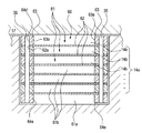
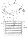
図1に示すように、第1実施形態に係る超音波式流体計測装置10は、左右の鉛直流路12,13と、この左右の鉛直流路12、13の上端部同士を連結する水平流路14とで略逆U字状に形成された流体路11を有している。水平流路14は流体を計測するための計測流路14aを有しており、この計測流路14aにおける一対の対向する内面15a,15bにはそれぞれ第1送受波器(ここでは送波器)21および第2送受波器(ここでは受波器)22を有する超音波計測部20が設けられている。さらに、計測流路14aには、流体を複数の扁平流路に区画する多層流路部材30と、多層流路部材30を計測流路14aに収容して密閉する蓋17を有している。従って、蓋17を水平流路14に被せると、計測流路14aは断面矩形の角筒状に形成されることになる。
As shown in FIG. 1, the ultrasonic
なお、第1送受波器21と第2送受波器22を結ぶ計測方向の超音波伝搬路23は、流体の流れる方向に対して斜めに交差するように設けられている。このように、第1,第2送受波器21,22のような流れに対して角度を有し対向して配置している配置パターンは、Zパス(Z−path)またはZ法と呼ばれており、本実施の形態では、このZパス配置について例示する。
The ultrasonic propagation path 23 in the measurement direction connecting the first transducer 21 and the
図1に示すように、水平流路14の側壁16a、16bには、外側へ突出する三角形状の送受波器取付部18、18がそれぞれ設けられている。両送受波器取付部18、18および側壁16a、16bには、両送受波器取付部18、18を結ぶ方向に貫通する例えば円形の貫通穴18aが設けられており、超音波伝播路が形成されている。なお、一方の送受波器取付部18には第1送受波器21が取り付けられ、他方の送受波器取付部18には第2送受波器22が取り付けられている。
As shown in FIG. 1, the
図2に示すように、本発明の第1実施形態にかかる多層流路部材30は、前述した超音波式流体計測装置10に形成された角筒状の計測流路14aに配置され、計測流路14aを複数の扁平流路14bに区画する仕切板32を有する。そして、仕切板32における流体の流れ方向に沿った縁部を支持するとともに、仕切板32の厚み方向に立ち上がる支持部33とを備える区画部材31を有しており、図3に示すように、区画部材31を複数積層させることにより多層流路部材30を形成している。
As shown in FIG. 2, the multilayer
図2および図3に示すように、仕切板32は矩形の板状部材であり、左右の両辺には各々矩形状の切欠き32aが設けられている。支持部33は所定の高さHを有する矩形断面を有する角部材であり、仕切板32の切欠き32aを挟む両側縁に合わせて、長材33aと短材33bとから構成されている。長材33aと短材33bの対向する端面には、上下方向にフィルタ用溝33eが形成されている。また、支持部33の内側面には全長にわたって嵌合溝33cが形成されており、この嵌合溝33cに仕切板32の両縁端部を嵌合させることにより、仕切板32を厚み方向に挟持している。また、支持部33には、上下方向に貫通する貫通穴33dが、所定位置に複数個設けられている。なお、仕切板32および支持部33は、金属あるは樹脂で形成することができる。
As shown in FIGS. 2 and 3, the
フィルタ34は、額縁状の枠体34aと、この枠体34aに取り付けられて、測定する流体を通さないが超音波を通す例えばメッシュやパンチングメタル等のフィルタ部材34bを有している。枠体34aの縦辺には、区画部材31の支持部34に設けられているフィルタ用溝33eに挿嵌可能な嵌合突起34cが上下方向に設けられている。なお、フィルタ部材34bには、撥水性処理を施すのが望ましい。これにより、フィルタ部材34bに当たった流体ははじかれ、流体による目詰まりが生じにくいので、計測精度を向上させることができる。
The
ここで、「撥水性」とは、防水のように「水の浸透を防ぐ」のではなく、「水を弾く」という性質を言う。撥水性処理としては、例えば、
1:大気圧下でプラズマを発生させ、材料表面に重合により撥水製のポリマーを生成させる。
2:フッ素の極薄皮膜を材料表面に設ける。
3:有機薄膜処理により素材の表面にナノスケールの機能膜を形成する。等の処理を例示することができる。
Here, “water repellency” refers to the property of “repelling water” rather than “preventing water penetration” like waterproofing. As a water repellent treatment, for example,
1: Plasma is generated under atmospheric pressure, and a water repellent polymer is generated on the surface of the material by polymerization.
2: An ultra-thin film of fluorine is provided on the material surface.
3: A nanoscale functional film is formed on the surface of the material by organic thin film treatment. Etc. can be exemplified.
従って、図1および図4に示すように、多層流路部材30を形成するには、まず、仕切板32の両縁端部を支持部33の嵌合溝33cに挿嵌して、区画部材31を複数枚形成しておく。そして、区画部材31の支持部33を上下方向に積層して多層流路部材30を形成する。このとき、支持部33の貫通穴33dに連結ピン35を挿入して、確実に位置決めして一体化するのが望ましい。そして、支持部33における長材33aと短材33bとの間に、フィルタ34を上から挿入して取り付ける。これにより、多層流路部材30Bが構成される。
Therefore, as shown in FIGS. 1 and 4, in order to form the multilayer
なお、図4に示すように、この多層流路部材30においては、最上段31aおよび最下段31bの流路の高さは、他の中央部の流路31cの高さと異なることになる。従って、最上段31aおよび最下段31bの高さを中央部に合わせるには、最上段31aの支持部33の上および最下段31bの支持部33の下に、仕切板32を有しない間隔調整用の支持部33f(図1参照)を設ける必要がある。
As shown in FIG. 4, in the multilayer
以上、説明した本発明の第1実施形態にかかる超音波式流体計測装置の多層流路部材30では、超音波式流体計測装置10に形成された角筒状の計測流路14aを扁平流路14bに区画する仕切板32を設ける際に、仕切板32の縁部を支持するとともに仕切板32の厚み方向に高さを有する区画部材31を配置したので、仕切板32を所定の間隔で保持することができる。また、区画部材31の高さによって仕切板32の間隔を決定するので、仕切板32の間隔を調整して、扁平流路14bの高さを調整することができる。このため、汎用性に富み、コストの低減化を図ることができる。
なお、前述した区画部材31では、仕切板32と支持部33を別体として形成したが、インサート成型により仕切板32と支持部33を一体的に形成することもできる。
As described above, in the multilayer
In the
(第2実施形態)
次に、本発明の第2実施形態にかかる超音波式流体計測装置の多層流路部材について、図面を用いて説明する。なお、前述した第1実施形態にかかる多層流路部材と共通する部位には同じ符号を付して、重複する説明を省略することとする。
図5は本発明の第2実施形態にかかる超音波式流体計測装置の多層流路部材を構成する区画部材の分解斜視図、図6は区画部材を積層して多層流路部材を形成する状態を示す斜視図、図7は多層流路部材の正面図である。
(Second Embodiment)
Next, the multilayer flow path member of the ultrasonic fluid measuring apparatus according to the second embodiment of the present invention will be described with reference to the drawings. In addition, the same code | symbol is attached | subjected to the site | part which is common in the multilayer flow-path member concerning 1st Embodiment mentioned above, and the overlapping description is abbreviate | omitted.
FIG. 5 is an exploded perspective view of the partition member constituting the multilayer flow path member of the ultrasonic fluid measuring apparatus according to the second embodiment of the present invention, and FIG. 6 is a state in which the multilayer member is formed by stacking the partition members. FIG. 7 is a front view of the multilayer flow path member.
図5に示すように、多層流路部材40を形成する区画部材41は、仕切板42と、仕切板42の片面(図5においては上面)に取り付けられた角柱状の支持部43とを有している。
As shown in FIG. 5, the
図5および図6に示すように、仕切板42は矩形の板状部材であり、左右の両辺には、支持部43の幅Wと同じ幅で矩形状の切欠き42aが各々設けられている。支持部43は所定の高さHを有する矩形断面を有する角部材であり、仕切板42の切欠き42aを挟む両側縁に合わせて、長材43aと短材43bとから構成されている。支持部43の下面には、仕切板42の厚さTと等しい深さTの仕切板用切欠き43eが形成されている。長材43aと短材43bの対向する端面には、上下方向にフィルタ用溝43cが形成されており、仕切板42の切欠き42aにもフィルタ用嵌合溝42bが形成されている。
As shown in FIGS. 5 and 6, the
また、支持部43および仕切板42の両縁部には、上下方向に貫通する貫通穴43c、42cが、対応する所定位置に複数個設けられている。なお、仕切板42および支持部43は、金属あるは樹脂で形成することができる。
In addition, a plurality of through
従って、図6および図7に示すように、多層流路部材40を形成するには、まず、支持部43(43a、43b)の下面の仕切板用切欠き43eに仕切板42の両縁端部が嵌合するように支持部43を仕切板42に取り付けて、区画部材41を複数枚形成しておく。そして、区画部材41の支持部43を上下方向に積層して多層流路部材40を形成する。このとき、支持部43の貫通穴43dおよび仕切板42の貫通穴42cに連結ピン35(図1参照)を挿入するのが望ましい。そして、支持部43において対向する長材43aと短材43bとの間、すなわち仕切板42の切欠き42aに、フィルタ34を上から挿入して取り付ける。このとき、フィルタ34の嵌合突起34cを、支持部43において対向する長材43aと短材43bのフィルタ用溝43cおよび仕切板42のフィルタ用溝42bに嵌合させてフィルタ34を取り付ける。これにより、多層流路部材40が構成される。
Therefore, as shown in FIGS. 6 and 7, in order to form the multilayer
なお、図7に示すように、この多層流路部材40において、最下段41aの流路の高さを他の中央部の流路41bの高さと合わせるには、最下段41aとして仕切板32を有しない間隔調整用の支持部43fを設ける必要がある。
As shown in FIG. 7, in this multilayer
以上、説明した本発明の第2実施形態にかかる超音波式流体計測装置の多層流路部材40でも、前述した第1実施形態にかかる超音波式流体計測装置の多層流路部材30と同様の効果を得ることができる。
なお、上述した多層流路部材40においては、仕切板42の上面に支持部43を設けて区画部材41を形成したが、仕切板42の下面に支持部43を設けて区画部材41を形成することもできる。
なお、前述した区画部材41では、仕切板42と支持部43を別体として形成したが、インサート成型により仕切板42と支持部43を一体的に形成することもできる。
As described above, the multilayer
In the multilayer
In the
(第3実施形態)
次に、本発明の第3実施形態にかかる超音波式流体計測装置の多層流路部材について、図面を用いて説明する。なお、前述した第1および第2実施形態にかかる多層流路部材と共通する部位には同じ符号を付して、重複する説明を省略することとする。
図8(A)は本発明の第2実施形態にかかる超音波式流体計測装置の多層流路部材を構成する区画部材の斜視図、図8(B)は同じく分解斜視図、図9は多層流路部材の正面図である。
(Third embodiment)
Next, the multilayer flow path member of the ultrasonic fluid measurement apparatus according to the third embodiment of the present invention will be described with reference to the drawings. In addition, suppose that the same code | symbol is attached | subjected to the site | part which is common in the multilayer flow path member concerning 1st and 2nd embodiment mentioned above, and the overlapping description is abbreviate | omitted.
FIG. 8A is a perspective view of a partition member constituting the multilayer flow path member of the ultrasonic fluid measuring apparatus according to the second embodiment of the present invention, FIG. 8B is an exploded perspective view, and FIG. It is a front view of a channel member.
図8に示すように、本発明の第3実施形態にかかる超音波式流体計測装置の多層流路部材50は、区画部材51が、仕切板52と、この仕切板52の両縁部全域に設けられた折曲部53と、各折曲部53の所定位置に設けられて超音波を透過するフィルタ部材53aと、仕切板52の片面(図8においては上面)に取り付けられるとともに折曲部53aに沿う角柱状の支持部54とを有している。
As shown in FIG. 8, the multi-layer
図8に示すように、仕切板52は矩形の板状部材であり、左右の両辺は直角に曲げ上げられて折曲部53が形成されている。支持部54は所定の高さHを有する矩形断面を有する角部材であり、仕切板52の折曲部53に設けられているフィルタ部材53aを挟む両側に合わせて、長材54aと短材54bとから構成されている。支持部54の下面には仕切板52の厚さTと等しい深さTの仕切板用切欠き54cが形成されており、支持部54の外側面には折曲部53の厚さ(すなわち、仕切板52の厚さ)Tと等しい深さTの折曲部用切欠き54dが形成されている。
As shown in FIG. 8, the
また、折曲部53の高さH1は、支持部54の高さHから仕切板52の板厚Tを減じた高さ、すなわち、H1=H−T に形成されている。このため、支持部54の仕切板用切欠き54cに仕切板52を嵌合させ、支持部54の折曲部用切欠き54dに折曲部53を嵌合させて仕切板52に支持部54を取り付けると、支持部54の上面と折曲部53の上面とが同一面上になる。
Further, the height H1 of the
また、支持部54および仕切板52の両縁部には、上下方向に貫通する貫通穴54e、52aが、対応する所定位置に複数個設けられている。なお、仕切板52および支持部54は、金属あるは樹脂で形成することができる。
Further, a plurality of through
従って、図9に示すように、多層流路部材50を形成するには、まず、支持部54(54a、54b)の下面の仕切板用切欠き54cに仕切板52の両縁端部が嵌合するとともに、支持部54の外側面の折曲部用切欠き54dに折曲部53が嵌合するように支持部54を仕切板52に取り付けて、区画部材51を複数枚形成しておく。そして、区画部材51の支持部54を上下方向に積層して多層流路部材50を形成する。このとき、支持部54の貫通穴54eおよび仕切板52の貫通穴52aに連結ピン35(図1参照)を挿入するのが望ましい。
Therefore, as shown in FIG. 9, in order to form the multilayer
なお、図9に示すように、この多層流路部材50において、最下段51aの流路の高さを他の中央部の流路51bの高さと合わせるには、最下段51aとして仕切板52を有しない間隔調整用の支持部54fを設ける必要がある。
As shown in FIG. 9, in this multilayer
以上、説明した本発明の第3実施形態にかかる超音波式流体計測装置の多層流路部材50でも、前述した第1および第2実施形態にかかる超音波式流体計測装置の多層流路部材30と同様の効果を得ることができる。さらに、多層流路部材50では、仕切板52の一部である折曲部53にフィルタ部材53aが設けられているので、前述したようなフィルタ34を別途設ける必要がない。
なお、前述した区画部材51では、仕切板52と支持部54を別体として形成したが、インサート成型により仕切板52と支持部54を一体的に形成することもできる。
As described above, the multilayer
In the
(第4実施形態)
次に、本発明の第4実施形態にかかる超音波式流体計測装置の多層流路部材について、図面を用いて説明する。なお、前述した第1〜第3実施形態にかかる多層流路部材と共通する部位には同じ符号を付して、重複する説明を省略することとする。
図10(A)は本発明の第2実施形態にかかる超音波式流体計測装置の多層流路部材を構成する区画部材の斜視図、図10(B)は同じく分解斜視図、図11は多層流路部材の正面図である。
(Fourth embodiment)
Next, the multilayer flow path member of the ultrasonic fluid measurement apparatus according to the fourth embodiment of the present invention will be described with reference to the drawings. In addition, suppose that the same code | symbol is attached | subjected to the site | part which is common in the multilayer flow path member concerning 1st-3rd embodiment mentioned above, and the overlapping description is abbreviate | omitted.
FIG. 10A is a perspective view of a partition member constituting the multilayer flow path member of the ultrasonic fluid measuring apparatus according to the second embodiment of the present invention, FIG. 10B is an exploded perspective view, and FIG. It is a front view of a channel member.
図10に示すように、本発明の第4実施形態にかかる超音波式流体計測装置の多層流路部材60は、区画部材61が、仕切板62と、この仕切板62の両縁部の所定位置に設けられた折曲部63と、各折曲部63に設けられて超音波を透過するフィルタ部材63aと、仕切板62の片面(図10では上面)に取り付けられるとともに折曲部63に沿う角柱状の支持部64とを有し、折曲部63の内面と支持部64の内面とが同一平面に沿う構成を有している。
As shown in FIG. 10, the multi-layer
図10に示すように、仕切板62は矩形の板状部材であり、左右の両辺における所定位置は直角に曲げ上げられて折曲部63が形成されている。支持部64は所定の高さHを有する矩形断面を有する角部材であり、仕切板62の折曲部63を挟む両側に合わせて、長材64aと短材64bとから構成されている。支持部64の下面には仕切板62の厚さTと等しい深さTの仕切板用切欠き64cが形成されている。
As shown in FIG. 10, the
また、折曲部63の高さH1は、支持部64の高さHから仕切板62の板厚Tを減じた高さ、すなわち、H1=H−T に形成されている。このため、支持部64の仕切板用切欠き64cに仕切板62を嵌合させて仕切板62に支持部64を取り付けると、支持部64の上面と折曲部63の上面とが同一面上になる。
Further, the height H1 of the
また、支持部64および仕切板62の両縁部には、上下方向に貫通する貫通穴64d、62aが、対応する所定位置に複数個設けられている。なお、仕切板62および支持部64は、金属あるは樹脂で形成することができる。
In addition, a plurality of through
従って、図11に示すように、多層流路部材60を形成するには、まず、支持部64(64a、64b)の下面の仕切板用切欠き64cに仕切板62の両縁端部が嵌合するとともに、折曲部63の両側に長材64aおよび短材64bを配置して支持部64を仕切板62に取り付けて、区画部材61を複数枚形成しておく。そして、区画部材61の支持部64を上下方向に積層して多層流路部材60を形成する。このとき、支持部64の貫通穴64dおよび仕切板62の貫通穴62aに連結ピン35(図1参照)を挿入するのが望ましい。
Therefore, as shown in FIG. 11, in order to form the multilayer
なお、図11に示すように、この多層流路部材60において、最下段61aの流路の高さを他の中央部の流路61bの高さと合わせるには、最下段61aとして仕切板62を有しない間隔調整用の支持部64eを設ける必要がある。
As shown in FIG. 11, in this multilayer
以上、説明した本発明の第4実施形態にかかる超音波式流体計測装置の多層流路部材60でも、前述した第1〜第3実施形態にかかる超音波式流体計測装置の多層流路部材と同様の効果を得ることができる。さらに、多層流路部材60では、仕切板62の一部である折曲部63にフィルタ部材63aが設けられているので、前述したようなフィルタ34を別途設ける必要がない。また、フィルタ部材63aの内面が、支持部64の内面と同一面となるので、流体の流れをスムーズに保持することができる。
なお、前述した区画部材61では、仕切板62と支持部64を別体として形成したが、インサート成型により仕切板62と支持部64を一体的に形成することもできる。
As described above, the multilayer
In the
(第5実施形態)
次に、本発明の第5実施形態にかかる超音波式流体計測装置の多層流路部材について、図面を用いて説明する。なお、前述した第1〜第4実施形態にかかる多層流路部材と共通する部位には同じ符号を付して、重複する説明を省略することとする。
図12(A)は本発明の第5実施形態にかかる超音波式流体計測装置の多層流路部材を構成する区画部材の斜視図、図12(B)は多層流路部材の正面図である。
(Fifth embodiment)
Next, the multilayer flow path member of the ultrasonic fluid measurement apparatus according to the fifth embodiment of the present invention will be described with reference to the drawings. In addition, suppose that the same code | symbol is attached | subjected to the site | part which is common in the multilayer flow-path member concerning 1st-4th embodiment mentioned above, and the overlapping description is abbreviate | omitted.
FIG. 12A is a perspective view of a partition member constituting the multilayer flow path member of the ultrasonic fluid measuring apparatus according to the fifth embodiment of the present invention, and FIG. 12B is a front view of the multilayer flow path member. .
図12(A)に示すように、本発明の第5実施形態にかかる超音波式流体計測装置の多層流路部材70を構成する区画部材71は仕切板72と支持部73を有しており、支持部73が、仕切板72の両縁部を折り曲げることにより形成されている。
As shown in FIG. 12A, the
図12(A)に示すように、仕切板72は矩形の板状部材であり、左右の両辺は直角に曲げ上げられて支持部73が形成されている。支持部73の上端部は内側へ折り曲げられて載置部73aが形成されており、区画部材71を重ねやすくしている。さらに、支持部73の前後両端部には、載置部73aを設けずにまっすぐ上方に突出して位置決め突起73bが設けられており、支持部73における位置決め突起73bの下方には、位置決め突起73bが嵌合する位置決め嵌合穴73cが形成されている。なお、支持部73の所定位置には、超音波を透過させるフィルタ部材34bが設けられている。
As shown in FIG. 12A, the
従って、図12(B)に示すように、多層流路部材70を形成するには、まず、仕切板72の左右両辺を曲げ上げて支持部73を形成する。このとき、支持部73の上端に載置部73aを設けるとともに、位置決め突起73bおよび位置決め嵌合穴73cを設けて、区画部材71を複数枚形成しておく。そして、区画部材71の支持部73を上下方向に積層して多層流路部材70を形成する。このとき、下側の区画部材71の位置決め突起73bを、上側に載置される区画部材71の位置決め嵌合穴73cに嵌合させて、確実に位置決めを行う。
Accordingly, as shown in FIG. 12B, in order to form the multilayer
なお、図12(B)に示すように、この多層流路部材70において、最上段71aの流路の高さを他の中央部の流路71bの高さと合わせるには、最上段71a用として、位置決め突起73bを有しない支持部73eを有する区画部材(71a)を設ける必要がある。
As shown in FIG. 12B, in this multilayer
以上、説明した本発明の第5実施形態にかかる超音波式流体計測装置の多層流路部材70でも、前述した第1〜第4実施形態にかかる超音波式流体計測装置の多層流路部材と同様の効果を得ることができる。さらに、多層流路部材70では、仕切板72の一部である支持部73にフィルタ部材34bが設けられているので、前述したようなフィルタ34を別途設ける必要がない。また、フィルタ部材34bの内面が、支持部73の内面と同一面となるので、流体の流れをスムーズに保持することができる。
As described above, the multilayer
(第6実施形態)
次に、本発明の第6実施形態にかかる超音波式流体計測装置の多層流路部材について、図面を用いて説明する。なお、前述した第1〜第5実施形態にかかる多層流路部材と共通する部位には同じ符号を付して、重複する説明を省略することとする。
図13(A)は本発明の第6実施形態にかかる超音波式流体計測装置の多層流路部材を構成する区画部材の斜視図、図13(B)は多層流路部材の正面図である。
(Sixth embodiment)
Next, the multilayer flow path member of the ultrasonic fluid measurement apparatus according to the sixth embodiment of the present invention will be described with reference to the drawings. In addition, the same code | symbol is attached | subjected to the site | part which is common in the multilayer flow-path member concerning 1st-5th embodiment mentioned above, and the overlapping description is abbreviate | omitted.
FIG. 13A is a perspective view of a partition member constituting the multilayer flow path member of the ultrasonic fluid measuring apparatus according to the sixth embodiment of the present invention, and FIG. 13B is a front view of the multilayer flow path member. .
図13(A)に示すように、本発明の第6実施形態にかかる超音波式流体計測装置の多層流路部材80を構成する区画部材81は、複数(図13(A)では2枚)の仕切板82a、82bと、各仕切板82a、82b間を連結する壁部83とを一体成型することにより扁平角筒状に形成されている。
As shown in FIG. 13A, there are a plurality of (two in FIG. 13A)
図13(A)に示すように、各仕切板82a、82bは矩形の板状部材であり、左右の両縁は左右の壁部83、83によって所定間隔で連結されており、全体矩形断面の区画部材81が形成されている。また、壁部83の前後両端部には、壁部83を上方へ延長して上方に突出する位置決め突起83aが設けられており、壁部83における位置決め突起83aの下方には、位置決め突起83aが嵌合する位置決め嵌合穴83bが形成されている。また、壁部83の所定位置には、超音波を透過させるフィルタ部材83cが設けられている。なお、位置決め突起83aは、一体成形により設けることができるが、一体成形後に仕切板82a、の一部を切起して形成することもできる。
As shown in FIG. 13A, each of the
従って、図13(B)に示すように、多層流路部材80を形成するには、まず、仕切板82a、82bと壁部83、83によって、内部に扁平流路14bを有する矩形断面の区画部材81を一体成形により複数個形成しておく。そして、区画部材81を上下方向に積層して多層流路部材80を形成する。このとき、下側の区画部材81の位置決め突起83aを、上側に載置される区画部材81の位置決め嵌合穴83bに嵌合させて、確実に位置決めを行う。
Therefore, as shown in FIG. 13B, in order to form the multilayer
以上、説明した本発明の第6実施形態にかかる超音波式流体計測装置の多層流路部材80でも、前述した第1〜第5実施形態にかかる超音波式流体計測装置の多層流路部材と同様の効果を得ることができる。さらに、多層流路部材80では、壁部83にフィルタ部材83cが設けられているので、前述したようなフィルタ34を別途設ける必要がない。また、各区画部材81は矩形の扁平流路14bを有しているので、最上段および最下段も、途中部分と同様に扁平流路14bが形成されることになる。
As described above, the multilayer
(第7実施形態)
次に、本発明の第7実施形態にかかる超音波式流体計測装置の多層流路部材について、図面を用いて説明する。なお、前述した第1〜第6実施形態にかかる多層流路部材と共通する部位には同じ符号を付して、重複する説明を省略することとする。
図14(A)は本発明の第7実施形態にかかる超音波式流体計測装置の多層流路部材を構成する区画部材の斜視図、図14(B)は多層流路部材の変形例を示す正面図である。
(Seventh embodiment)
Next, the multilayer flow path member of the ultrasonic fluid measurement apparatus according to the seventh embodiment of the present invention will be described with reference to the drawings. In addition, the same code | symbol is attached | subjected to the site | part which is common in the multilayer flow-path member concerning 1st-6th embodiment mentioned above, and the overlapping description is abbreviate | omitted.
FIG. 14A is a perspective view of a partition member constituting the multilayer flow path member of the ultrasonic fluid measurement device according to the seventh embodiment of the present invention, and FIG. 14B shows a modification of the multilayer flow path member. It is a front view.
図14(A)に示すように、本発明の第7実施形態にかかる超音波式流体計測装置の多層流路部材を構成する区画部材91は、複数(図14(A)においては2枚)の仕切板92a、92bと、各仕切板92a、92b間を連結する壁部93とを一体成型することにより略コ字状に形成されている。
As shown in FIG. 14 (A), there are a plurality (two in FIG. 14 (A)) of
図14(A)に示すように、各仕切板92a、92bは矩形の板状部材であり、左右いずれかの縁部は壁部93によって所定間隔で連結されており、全体コ字状の区画部材91が形成されている。また、壁部93の前後両端部には、壁部93を上方へ延長して上方に突出する位置決め突起93aが設けられており、下側の仕切板92bにおける位置決め突起93aの下方位置には、位置決め突起93aが嵌合する位置決め嵌合穴93bが形成されている。また、壁部93の所定位置には、超音波を透過させるフィルタ部材93cが設けられている。
As shown in FIG. 14 (A), each
従って、多層流路部材を形成するには、まず、仕切板92a、92bと壁部93によって、内部に扁平流路14bを有する断面コ字状の区画部材91を一体成形により複数個形成しておく。そして、区画部材91を上下方向に積層して多層流路部材を形成する。このとき、下側の区画部材91の位置決め突起93aを、上側に載置される区画部材91の位置決め嵌合穴93bに嵌合させて、確実に位置決めを行う。
Therefore, in order to form a multi-layer flow path member, first, a plurality of
以上、説明した本発明の第7実施形態にかかる超音波式流体計測装置の多層流路部材でも、前述した第1〜第6実施形態にかかる超音波式流体計測装置の多層流路部材と同様の効果を得ることができる。さらに、多層流路部材では、壁部93にフィルタ部材93cが設けられているので、前述したようなフィルタ34を別途設ける必要がない。また、各区画部材91は矩形の扁平流路14bを有しているので、最上段および最下段も、途中部分と同様に扁平流路14bが形成されることになる。
The multilayer flow path member of the ultrasonic fluid measurement apparatus according to the seventh embodiment of the present invention described above is the same as the multilayer flow path member of the ultrasonic fluid measurement apparatus according to the first to sixth embodiments described above. The effect of can be obtained. Further, in the multilayer flow path member, the
なお、図14(B)に示す区画部材91Bでは、3枚の仕切板92a、92b、92cを壁部93によってS字形状に連結されている。この場合は、図14(A)において前述した区画部材91を2個つなげたものと等しいので、同様の作用・効果を得ることができる。なお、位置決め突起93aは最上の仕切板92aに設け、位置決め嵌合穴93bは最下の仕切板92cに設けることになる。
In the
なお、本発明の超音波式流体計測装置の多層流路部材は、前述した各実施形態に限定されるものでなく、適宜な変形,改良等が可能である。
例えば、図15および図16に示すように、上流側、下流側の扁平流路14bを更に区画して正方形の流路を形成するための間仕切板36を設けるようにしてもよい。間仕切版36および仕切板32には、互いに相手を挿入することができる切欠き36a、32bがそれぞれ同じ長さで設けられている。また、間仕切版36は、仕切板32に取り付けた際に、超音波の通路を干渉しないような大きさで形成されている。なお、図15は第1実施形態の場合を例として示し、図16では第2実施形態の場合を例として示しているが、その他の実施形態にも同様に適用することができる。
In addition, the multilayer flow path member of the ultrasonic fluid measuring device of the present invention is not limited to the above-described embodiments, and appropriate modifications and improvements can be made.
For example, as shown in FIGS. 15 and 16, a
また、図17(A)〜(C)に示すように、支持部の形状を変化させることができる。すなわち、図17(A)に示す支持部33を上下に2分割して上支持部33Uおよび下支持部33Lを形成し、上支持部33Uと下支持部33Lとの間に仕切板32を挟持することができる。なお、上支持部33Uと下支持部33Lとは、超音波溶着や接着材で接合することができる。
Moreover, as shown to FIG. 17 (A)-(C), the shape of a support part can be changed. That is, the
また、図17(B)に示す支持部33では、支持部33の上面に凸部33gを設けるとともに、支持部33の下面には凸部33gが嵌合する凹部33hを設けてある。これにより、積層する上下の支持部33の位置決めを確実に行うことができる。なお、凸部33gおよび凹部33hは、点状に設けるものでもよいし、支持部33に沿って長く設けるものでもよい。
In addition, in the
また、図17(C)に示す支持部33では、上下の支持部33を組み合わせた際に、内部に空間33jを形成するようにした。このように空間33jを設けることにより、超音波溶着の際に、効果的に溶着することができる。
In the
さらに、本発明は、図18に示す区画部材131を含むものである。
なお、以下に説明する区画部材131において、前述した第1実施形態の区画部材31と同様な箇所については同等符号を付して説明を省略する。
図18(A)に示す区画部材131は、支持部133(133a、133b)に設けられたテーパ形状の接続ピン133dと、接続ピン133dを挿入する接続穴133fとが設けられている。
Furthermore, the present invention includes a
In the
The
接続ピン133dは、先端に向かって先細りとなる略円錐形状とされ、その軸線が接続穴133fの軸線の延長線に沿うように配置されている。また、接続ピン133dの高さ寸法が接続穴133fの深さ寸法よりも若干小さく設定されているとともに、接続ピン133dの基端の大径部の直径寸法が接続穴133fの開口直径寸法よりも若干小さく設定されている。
The
図18(B)に示すように、このような区画部材131を他の区画部材131と積層させると、接続ピン133dが上方の他の区画部材131の接続穴133fに挿入され、
接続穴133fに下方の他の区画部材131の接続ピン133dが挿入され、これにより第1実施形態において例示した連結ピンを用いることなく、各区画部材131を積層させた状態で固定できる。
この際、接続ピン133dおよび接続穴133fが前述した寸法に設定されているため、接続ピン133dの頭頂部と接続穴133fの底部とが接触することなく、当該間に隙間Sが生じる。このため、接続穴133fの開口縁部に対して接続ピン133dのテーパ面が線接触した状態で嵌入され、これにより各区画部材131にガタが生じる虞はない。
As shown in FIG. 18B, when such a
The
At this time, since the
以上のような区画部材131によれば、支持部に接続ピン133dおよび接続穴133fが設けられているため、他の区画部材131を積層させた状態で固定するための連結ピンが不要となり、製造コストを低減できる。
また、この区画部材131は、接続ピン133dがテーパ面を有するテーパ形状であるため、他の区画部材131と積層させた状態でガタが生じない。
According to the
In addition, since the
なお、本発明は、図19に示す区画部材231、331を含むものである。
すなわち、図19(A)に示す区画部材231は、略円柱形状の接続ピン233dと、奥行き方向に向かって先細りとなる接続穴233fとが設けられている。
また、図19(B)に示す区画部材331は、先端に向かって先細りとなる略円錐形状の接続ピン333dと、奥行き方向に向かって先細りとなる接続穴333fとが設けられている。
これらの区画部材231、331においても、同様な効果が得られる。
The present invention includes
That is, the
Further, the
Similar effects can be obtained with these
以上のように、本発明にかかる超音波式流体計測装置の多層流路部材は、超音波式流体計測装置に形成された角筒状の計測流路を扁平流路に区画する仕切板を設ける際に、仕切板の縁部を支持するとともに仕切板の厚み方向に高さを有する区画部材を配置したので、仕切板を所定の間隔で保持することができる。また、区画部材の高さによって仕切板の間隔を決定するので、仕切板の間隔を調整して、扁平流路の高さを調整することができる。このため、汎用性に富み、コストの低減化を図ることができるという効果を有し、超音波式流体計測装置に形成された角筒状の計測流路に配置され、この計測流路を複数の扁平流路に区画する仕切板を有する超音波式流体計測装置の多層流路部材等として有用である。 As described above, the multilayer flow path member of the ultrasonic fluid measurement device according to the present invention is provided with the partition plate that divides the rectangular tubular measurement flow channel formed in the ultrasonic fluid measurement device into flat flow channels. At this time, since the partition member that supports the edge of the partition plate and has a height in the thickness direction of the partition plate is disposed, the partition plate can be held at a predetermined interval. Moreover, since the space | interval of a partition plate is determined by the height of a partition member, the space | interval of a partition plate can be adjusted and the height of a flat flow path can be adjusted. For this reason, it is rich in versatility and has the effect of being able to reduce costs, and is arranged in a rectangular tube-shaped measurement channel formed in the ultrasonic fluid measurement device. It is useful as a multilayer flow path member or the like of an ultrasonic fluid measuring device having a partition plate partitioned into flat flow paths.
10 超音波式流体計測装置
14a 計測流路
14b 扁平流路
30、40、50、60、70、80 多層流路部材
31、41、51、61、71、81、91、131、231、331 区画部材
32、42、52、62、72、82a、82b、92a、92b 仕切板
33、43、53、64、73、133a、133b 支持部
35 連結ピン
53、63 折曲部
34b フィルタ部材
83、93 壁部
DESCRIPTION OF
Claims (12)
前記仕切板における流体の流れ方向に沿った縁部を支持するとともに、前記仕切板の厚み方向に立ち上がる支持部とを備える区画部材を有し、
前記支持部の一部に超音波を透過する為の切欠きが形成され、
前記区画部材を複数積層させることにより形成されていることを特徴とする超音波式流体計測装置の多層流路部材。 A multilayer flow path member of an ultrasonic fluid measurement apparatus having a partition plate arranged in a rectangular tube-shaped measurement flow path formed in an ultrasonic fluid measurement apparatus and dividing the measurement flow path into a plurality of flat flow paths. There,
A partition member that supports an edge portion in the fluid flow direction in the partition plate and includes a support portion that rises in the thickness direction of the partition plate,
A notch for transmitting ultrasonic waves is formed in a part of the support part,
A multilayer flow path member of an ultrasonic fluid measuring device, wherein the multilayer fluid member is formed by laminating a plurality of the partition members.
前記折曲部の内面と前記支持部の内面とが同一平面に沿うことを特徴とする請求項1に記載の超音波式流体計測装置の多層流路部材。 The partition member is the partition plate, a bent portion provided at a predetermined position of both edges of the partition plate, a filter member provided at each bent portion and transmitting ultrasonic waves, and the partition plate And a prismatic support portion along the bent portion and attached to one side of
The multilayer flow path member for an ultrasonic fluid measuring device according to claim 1, wherein an inner surface of the bent portion and an inner surface of the support portion are along the same plane.
Priority Applications (6)
| Application Number | Priority Date | Filing Date | Title |
|---|---|---|---|
| JP2007179952A JP4986748B2 (en) | 2007-07-09 | 2007-07-09 | Multi-layer flow path member of ultrasonic fluid measuring device |
| PCT/JP2008/001838 WO2009008167A1 (en) | 2007-07-09 | 2008-07-09 | Multilayer channel member of ultrasonic fluid measuring device and ultrasonic fluid measuring device |
| EP08790190A EP2180298A4 (en) | 2007-07-09 | 2008-07-09 | MULTILAYER CHANNEL ELEMENT OF ULTRASONIC FLUID MEASURING DEVICE AND ULTRASONIC FLUID MEASURING DEVICE |
| CN200880023620XA CN101688800B (en) | 2007-07-09 | 2008-07-09 | Multilayer flow path member of ultrasonic fluid measuring device and ultrasonic fluid measuring device |
| CN2012100166084A CN102589625A (en) | 2007-07-09 | 2008-07-09 | Multilayer channel member of ultrasonic fluid measuring device and ultrasonic fluid measuring device |
| US12/668,171 US8161824B2 (en) | 2007-07-09 | 2008-07-09 | Multilayer flow path member of ultrasonic fluid measurement apparatus and ultrasonic fluid measurement apparatus |
Applications Claiming Priority (1)
| Application Number | Priority Date | Filing Date | Title |
|---|---|---|---|
| JP2007179952A JP4986748B2 (en) | 2007-07-09 | 2007-07-09 | Multi-layer flow path member of ultrasonic fluid measuring device |
Publications (2)
| Publication Number | Publication Date |
|---|---|
| JP2009014672A JP2009014672A (en) | 2009-01-22 |
| JP4986748B2 true JP4986748B2 (en) | 2012-07-25 |
Family
ID=40355732
Family Applications (1)
| Application Number | Title | Priority Date | Filing Date |
|---|---|---|---|
| JP2007179952A Expired - Fee Related JP4986748B2 (en) | 2007-07-09 | 2007-07-09 | Multi-layer flow path member of ultrasonic fluid measuring device |
Country Status (1)
| Country | Link |
|---|---|
| JP (1) | JP4986748B2 (en) |
Cited By (2)
| Publication number | Priority date | Publication date | Assignee | Title |
|---|---|---|---|---|
| JP2016205841A (en) * | 2015-04-16 | 2016-12-08 | パナソニックIpマネジメント株式会社 | Flow rate measurement apparatus |
| EP4528232A4 (en) * | 2022-05-16 | 2025-08-20 | Panasonic Ip Man Co Ltd | FLOW CHANNEL DEVICE FOR FLUID MEASUREMENT AND ULTRASONIC FLOW RATE METER THEREFOR |
Families Citing this family (6)
| Publication number | Priority date | Publication date | Assignee | Title |
|---|---|---|---|---|
| JP4648486B2 (en) | 2009-01-26 | 2011-03-09 | ファナック株式会社 | Production system with cooperative operation area between human and robot |
| EP2443422A1 (en) * | 2009-06-19 | 2012-04-25 | Metricon Ilektronika-Metritika Sistimata E.P.E. | Device for volume measuring and quality control of liquid fuel |
| JPWO2012137489A1 (en) * | 2011-04-05 | 2014-07-28 | パナソニック株式会社 | Ultrasonic flow measuring device |
| JP6180759B2 (en) * | 2012-09-07 | 2017-08-16 | 矢崎エナジーシステム株式会社 | Flow measuring device |
| JP6145645B2 (en) | 2013-06-19 | 2017-06-14 | パナソニックIpマネジメント株式会社 | Ultrasonic flow meter |
| JP6488463B2 (en) * | 2016-02-29 | 2019-03-27 | パナソニックIpマネジメント株式会社 | Gas meter |
Family Cites Families (7)
| Publication number | Priority date | Publication date | Assignee | Title |
|---|---|---|---|---|
| JP3345322B2 (en) * | 1997-10-31 | 2002-11-18 | 株式会社山武 | Flowmeter |
| JPH11311556A (en) * | 1998-04-28 | 1999-11-09 | Yazaki Corp | Multi-layer fluid vibration type flow meter |
| JP4447205B2 (en) * | 2002-10-15 | 2010-04-07 | パナソニック株式会社 | Ultrasonic flow meter |
| JP3487307B1 (en) * | 2002-11-01 | 2004-01-19 | 松下電器産業株式会社 | Fluid flow measurement device |
| JP2004316685A (en) * | 2003-04-11 | 2004-11-11 | Yazaki Corp | Flow path unit, laminated portion, and method of manufacturing the laminated portion |
| JP4406901B2 (en) * | 2003-07-03 | 2010-02-03 | 株式会社山武 | Fluid rectifier |
| JP4459734B2 (en) * | 2004-06-30 | 2010-04-28 | 東洋ガスメーター株式会社 | Gas meter |
-
2007
- 2007-07-09 JP JP2007179952A patent/JP4986748B2/en not_active Expired - Fee Related
Cited By (2)
| Publication number | Priority date | Publication date | Assignee | Title |
|---|---|---|---|---|
| JP2016205841A (en) * | 2015-04-16 | 2016-12-08 | パナソニックIpマネジメント株式会社 | Flow rate measurement apparatus |
| EP4528232A4 (en) * | 2022-05-16 | 2025-08-20 | Panasonic Ip Man Co Ltd | FLOW CHANNEL DEVICE FOR FLUID MEASUREMENT AND ULTRASONIC FLOW RATE METER THEREFOR |
Also Published As
| Publication number | Publication date |
|---|---|
| JP2009014672A (en) | 2009-01-22 |
Similar Documents
| Publication | Publication Date | Title |
|---|---|---|
| JP4986748B2 (en) | Multi-layer flow path member of ultrasonic fluid measuring device | |
| US8978482B2 (en) | Partition plate securement for an ultrasonic flow meter | |
| WO2008035744A1 (en) | Ultrasonic type fluid measurement device | |
| EP2180298A1 (en) | Multilayer channel member of ultrasonic fluid measuring device and ultrasonic fluid measuring device | |
| JP5927394B1 (en) | Sensor clamp device, clamp-on type ultrasonic flowmeter | |
| JP6296775B2 (en) | Microchannel heat exchanger | |
| JP6229143B2 (en) | Flow measuring device | |
| CN205748512U (en) | Coupling structure, ultrasonic transducer and ultrasonic flowmeter | |
| JP6145645B2 (en) | Ultrasonic flow meter | |
| WO2011148618A1 (en) | Ultrasonic probe and method of manufacturing thereof | |
| JP4665620B2 (en) | Inkjet printer head and manufacturing method thereof | |
| JP2016205841A (en) | Flow rate measurement apparatus | |
| JP5445323B2 (en) | Acoustic transducer | |
| US9525948B2 (en) | Electro-acoustic transducer | |
| JP4898724B2 (en) | Method for manufacturing multilayer flow path member of ultrasonic fluid measuring device | |
| JP5225625B2 (en) | Ultrasonic fluid measuring device | |
| JP7777752B2 (en) | Vibration transmission member, and vibration transducer, measuring instrument, and concentration meter using the same | |
| JP5261152B2 (en) | Ultrasonic transducer | |
| JP5213218B2 (en) | Multi-layer flow path member of ultrasonic fluid measuring device | |
| EP3648475A1 (en) | Acoustic matching layer | |
| JP2014214934A (en) | Plate heat exchanger | |
| JP2009014658A (en) | Multi-layer flow path member of ultrasonic fluid measuring device and ultrasonic fluid measuring device | |
| JP2006292381A (en) | Ultrasonic flow meter | |
| JP4898723B2 (en) | Multi-layer flow path member of ultrasonic fluid measuring device | |
| JP2009014673A (en) | Multi-layer flow path member of ultrasonic fluid measuring device |
Legal Events
| Date | Code | Title | Description |
|---|---|---|---|
| A621 | Written request for application examination |
Free format text: JAPANESE INTERMEDIATE CODE: A621 Effective date: 20081202 |
|
| A131 | Notification of reasons for refusal |
Free format text: JAPANESE INTERMEDIATE CODE: A131 Effective date: 20110906 |
|
| A521 | Written amendment |
Free format text: JAPANESE INTERMEDIATE CODE: A523 Effective date: 20111107 |
|
| TRDD | Decision of grant or rejection written | ||
| A01 | Written decision to grant a patent or to grant a registration (utility model) |
Free format text: JAPANESE INTERMEDIATE CODE: A01 Effective date: 20120327 |
|
| A01 | Written decision to grant a patent or to grant a registration (utility model) |
Free format text: JAPANESE INTERMEDIATE CODE: A01 |
|
| A61 | First payment of annual fees (during grant procedure) |
Free format text: JAPANESE INTERMEDIATE CODE: A61 Effective date: 20120424 |
|
| R150 | Certificate of patent or registration of utility model |
Free format text: JAPANESE INTERMEDIATE CODE: R150 |
|
| FPAY | Renewal fee payment (event date is renewal date of database) |
Free format text: PAYMENT UNTIL: 20150511 Year of fee payment: 3 |
|
| LAPS | Cancellation because of no payment of annual fees |