JP5716613B2 - Fuel cell - Google Patents

Fuel cell Download PDF

Info

Publication number
JP5716613B2
JP5716613B2 JP2011191161A JP2011191161A JP5716613B2 JP 5716613 B2 JP5716613 B2 JP 5716613B2 JP 2011191161 A JP2011191161 A JP 2011191161A JP 2011191161 A JP2011191161 A JP 2011191161A JP 5716613 B2 JP5716613 B2 JP 5716613B2
Authority
JP
Japan
Prior art keywords
separator
fuel cell
hydrogen
manifold
oxygen
Prior art date
Legal status (The legal status is an assumption and is not a legal conclusion. Google has not performed a legal analysis and makes no representation as to the accuracy of the status listed.)
Active
Application number
JP2011191161A
Other languages
Japanese (ja)
Other versions
JP2013054872A (en
Inventor
飯塚 和孝
和孝 飯塚
和田 三喜男
三喜男 和田
Current Assignee (The listed assignees may be inaccurate. Google has not performed a legal analysis and makes no representation or warranty as to the accuracy of the list.)
Toyota Motor Corp
Original Assignee
Toyota Motor Corp
Priority date (The priority date is an assumption and is not a legal conclusion. Google has not performed a legal analysis and makes no representation as to the accuracy of the date listed.)
Filing date
Publication date
Application filed by Toyota Motor Corp filed Critical Toyota Motor Corp
Priority to JP2011191161A priority Critical patent/JP5716613B2/en
Publication of JP2013054872A publication Critical patent/JP2013054872A/en
Application granted granted Critical
Publication of JP5716613B2 publication Critical patent/JP5716613B2/en
Active legal-status Critical Current
Anticipated expiration legal-status Critical

Links

Images

Classifications

    • YGENERAL TAGGING OF NEW TECHNOLOGICAL DEVELOPMENTS; GENERAL TAGGING OF CROSS-SECTIONAL TECHNOLOGIES SPANNING OVER SEVERAL SECTIONS OF THE IPC; TECHNICAL SUBJECTS COVERED BY FORMER USPC CROSS-REFERENCE ART COLLECTIONS [XRACs] AND DIGESTS
    • Y02TECHNOLOGIES OR APPLICATIONS FOR MITIGATION OR ADAPTATION AGAINST CLIMATE CHANGE
    • Y02EREDUCTION OF GREENHOUSE GAS [GHG] EMISSIONS, RELATED TO ENERGY GENERATION, TRANSMISSION OR DISTRIBUTION
    • Y02E60/00Enabling technologies; Technologies with a potential or indirect contribution to GHG emissions mitigation
    • Y02E60/30Hydrogen technology
    • Y02E60/50Fuel cells

Landscapes

  • Fuel Cell (AREA)

Description

この発明は、燃料電池に関する。   The present invention relates to a fuel cell.

燃料電池としては、発電体である膜電極接合体をセパレータによって狭持した発電モジュールである単セルを、複数個積層したスタック構造を有するものが知られている(下記特許文献1等)。燃料電池は、一般に、車両などの限られた空間内に搭載される。そのため、燃料電池は、単セルを薄型化するなど、小型化されることが望ましい。また、燃料電池は、小型化された場合であっても、その内部に形成される反応ガスのための流路の圧力損失が増大してしまわないように構成されていることが好ましい。さらに、燃料電池では、一部の単セルのみに不具合が生じる場合があるため、単セルが交換可能に構成されることによって、保守性(メンテナンス性)が向上されていることが望ましい。   As a fuel cell, one having a stack structure in which a plurality of single cells, which are power generation modules in which a membrane electrode assembly, which is a power generation body, is sandwiched by separators is stacked is known (Patent Document 1 below). A fuel cell is generally mounted in a limited space such as a vehicle. Therefore, it is desirable that the fuel cell be downsized, for example, by making the single cell thinner. In addition, even when the fuel cell is downsized, it is preferable that the fuel cell is configured so as not to increase the pressure loss of the flow path for the reaction gas formed therein. Further, in a fuel cell, there may be a problem in only some of the single cells. Therefore, it is desirable that maintainability (maintenability) be improved by configuring the single cells to be replaceable.

特開2010−205593号公報JP 2010-205593 A 特開2006−221905号公報JP 2006-221905 A 特開2009−093850号公報JP 2009-093850 A

本発明は、反応ガスの圧力損失の増大を抑制しつつ、燃料電池を小型化するとともに、燃料電池のメンテナンス性を向上させる技術を提供することを目的とする。   An object of the present invention is to provide a technique for reducing the size of a fuel cell and improving the maintainability of the fuel cell while suppressing an increase in the pressure loss of the reaction gas.

本発明は、上述の課題の少なくとも一部を解決するためになされたものであり、以下の形態又は適用例として実現することが可能である。   SUMMARY An advantage of some aspects of the invention is to solve at least a part of the problems described above, and the invention can be implemented as the following forms or application examples.

[適用例1]
複数の発電モジュールが積層された積層構造を有する燃料電池であって、前記発電モジュールは、電解質膜の両面に第1と第2の電極が配置された膜電極接合体と、前記膜電極接合体の前記第1と第2の電極のそれぞれに対応して配置され、前記第1の電極に供給される第1の反応ガスのための第1のマニホールドを構成する貫通孔が形成された第1と第2のセパレータと、前記膜電極接合体の外周において前記第1と第2のセパレータとを接着する接着層と、を備え、前記接着層には、厚み方向に貫通し、前記第1のマニホールドを構成する第1のマニホールド流路と、前記第1のマニホールド流路と、前記膜電極接合体の前記第1の電極との間を連通する第1の連通路と、が設けられ、前記第1の連通路には、前記第1のマニホールド流路との接続部において、前記第1のマニホールドの貫通方向に突出する第1の通路壁部が配置されている、燃料電池。
この燃料電池によれば、接着層に第1の反応ガスのための第1のガス通路が設けられており、各発電モジュールをコンパクトに構成することができる。従って、燃料電池の小型化が可能である。そして、燃料電池を小型化した場合であっても、補強部としても機能する第1の通路壁部によって、第1のマニホールド流路と第1の連通路との接続部が閉塞されてしまう可能性が低減され、燃料電池における反応ガスの圧力損失の増大が抑制される。また、各発電モジュールが接着層により一体化された構成を有しているため、燃料電池において、不具合を生じている一部の発電モジュールのみの交換が容易となり、そのメンテナンス性が向上する。
[Application Example 1]
A fuel cell having a stacked structure in which a plurality of power generation modules are stacked, wherein the power generation module includes a membrane electrode assembly in which first and second electrodes are disposed on both surfaces of an electrolyte membrane, and the membrane electrode assembly. A first hole disposed corresponding to each of the first electrode and the second electrode, and having a through-hole forming a first manifold for a first reaction gas supplied to the first electrode. And a second separator, and an adhesive layer that adheres the first and second separators on the outer periphery of the membrane electrode assembly, the adhesive layer penetrating in the thickness direction, and the first A first manifold channel that forms a manifold, a first communication channel that communicates between the first manifold channel and the first electrode of the membrane electrode assembly, and In the first communication passage, the first manifold flow is provided. In connection portion of the first passage wall portion protruding into the through direction of the first manifold is disposed, the fuel cell.
According to this fuel cell, the first gas passage for the first reaction gas is provided in the adhesive layer, and each power generation module can be configured compactly. Therefore, the fuel cell can be reduced in size. Even when the fuel cell is downsized, the connection portion between the first manifold channel and the first communication path may be blocked by the first passage wall portion that also functions as the reinforcing portion. And the increase in the pressure loss of the reaction gas in the fuel cell is suppressed. In addition, since each power generation module has a configuration in which the power generation modules are integrated by the adhesive layer, it is easy to replace only a part of the power generation modules in which a problem occurs in the fuel cell, and the maintainability is improved.

[適用例2]
適用例1記載の燃料電池であって、前記接着層は、前記膜電極接合体の前記第2の電極の外周において、前記第1の反応ガスが前記第2の電極へと流入することを抑制するとともに、前記膜電極接合体と前記第2のセパレータとを接着する第1の接着部を有し、前記第1の接着部は、前記第1の通路壁部から離間して設けられている、燃料電池。
この燃料電池によれば、第1の連通路の一部を構成する第1の接着部を形成する際に、接着剤によって第1の通路壁部によって形成されるガス通路が閉塞されてしまう可能性が低減される。
[Application Example 2]
The fuel cell according to Application Example 1, wherein the adhesive layer suppresses the first reactive gas from flowing into the second electrode on the outer periphery of the second electrode of the membrane electrode assembly. And having a first adhesive part for adhering the membrane electrode assembly and the second separator, wherein the first adhesive part is provided apart from the first passage wall part. ,Fuel cell.
According to this fuel cell, the gas passage formed by the first passage wall portion may be blocked by the adhesive when the first adhesive portion constituting a part of the first communication passage is formed. Is reduced.

[適用例3]
適用例1または適用例2記載の燃料電池であって、前記発電モジュールは、さらに、前記第2のセパレータと前記第2の電極との間に配置され、前記第2の反応ガスを前記第2の電極の面に沿って拡散させるためのガス拡散部材を備え、前記第1と第2のセパレータには、前記第2の電極に供給される第2の反応ガスのための第2のマニホールドを構成する貫通孔が形成されており、前記接着層には、厚み方向に貫通し、前記第2のマニホールドを構成する第2のマニホールド流路と、前記第2のマニホールド流路と、前記ガス拡散部材との間を連通する第2の連通路と、が設けられ、前記第2の連通路には、前記第2のマニホールド流路との接続部において、前記第2のマニホールド流路の貫通方向に沿って突出する第2の通路壁部が配置され、前記第2のセパレータには、前記ガス拡散部材の端部が配置される位置に、前記第2の連通路と連結し、前記第2の反応ガスを、前記第2のセパレータの外表面側から前記ガス拡散部材に流入させるための溝部が設けられている、燃料電池。
この燃料電池によれば、第2の反応ガスのための第2の連通路についても、第1の反応ガスのための第1の連通路と同様に、第2の通路壁部によって、第2のマニホールド流路との接続部における閉塞が抑制される。また、第2のセパレータに設けられた溝部によって、ガス拡散部材に第2の反応ガスが流入する際の圧力損失が低減される。
[Application Example 3]
The fuel cell according to Application Example 1 or Application Example 2, wherein the power generation module is further disposed between the second separator and the second electrode, and the second reaction gas is supplied to the second reaction gas. A gas diffusion member for diffusing along the surface of the second electrode, and the first and second separators are provided with a second manifold for the second reaction gas supplied to the second electrode. A through-hole is formed, and the adhesive layer penetrates in the thickness direction, and forms a second manifold channel that constitutes the second manifold, the second manifold channel, and the gas diffusion A second communication passage that communicates with the member, and the second communication passage includes a second manifold passage at a connection portion with the second manifold passage. 2nd passage wall part protruding along The second separator is connected to the second communication path at a position where the end of the gas diffusion member is disposed, and the second reaction gas is supplied to the outer surface of the second separator. A fuel cell provided with a groove for flowing into the gas diffusion member from the side.
According to this fuel cell, the second communication passage for the second reaction gas is also formed by the second passage wall portion in the same manner as the first communication passage for the first reaction gas. Blockage at the connection portion with the manifold flow path is suppressed. Further, the groove provided in the second separator reduces the pressure loss when the second reaction gas flows into the gas diffusion member.

[適用例4]
適用例3記載の燃料電池であって、前記接着層は、前記第1の電極の外周において、前記第2の反応ガスが前記第1の電極へと流入することを抑制するとともに、前記膜電極接合体と、前記第1のセパレータとを接着する第2の接着部を有し、前記第2の連通路は、前記第2の接着部と、前記第2のセパレータに設けられた前記溝部とを離間する壁部を有する、燃料電池。
この燃料電池によれば、第2のガス通路において、ガス拡散部材に連結する溝部と第2の接着部とを離間するための壁部が設けられている。そのため、第2の接着部を形成する際に、接着剤の一部が、第2の反応ガスがガス拡散部材に流入するための流路を閉塞してしまうことを抑制できる。
[Application Example 4]
The fuel cell according to Application Example 3, wherein the adhesive layer suppresses the second reactive gas from flowing into the first electrode on the outer periphery of the first electrode, and the membrane electrode A second bonded portion that bonds the joined body and the first separator; and the second communication path includes the second bonded portion and the groove portion provided in the second separator. A fuel cell having a wall part separating the two.
According to this fuel cell, in the second gas passage, the wall portion for separating the groove portion connected to the gas diffusion member and the second adhesive portion is provided. Therefore, when forming the 2nd adhesion part, it can control that some adhesives block the channel for the 2nd reaction gas to flow into the gas diffusion member.

[適用例5]
適用例3または適用例4記載の燃料電池であって、前記第1と第2の通路壁部は、前記第2のセパレータを、厚み方向に沿って凹凸させることにより形成されており、前記第1と第2の通路壁部の形成された面とは反対側の面に形成される凹部には樹脂部材が充填され、前記樹脂部材の下には、シール部材が配置されている、燃料電池。
この燃料電池によれば、第1と第2の通路壁部を効率的に形成できる。また、第1と第2の通路壁部を設けたことによって形成された凹部には、樹脂部材が充填されるため、その凹部の下にシールラインが形成される場合であっても、燃料電池のシール性が低下してしまうことが抑制される。
[Application Example 5]
The fuel cell according to Application Example 3 or Application Example 4, wherein the first and second passage wall portions are formed by making the second separator uneven in the thickness direction, A fuel cell in which a concave portion formed on a surface opposite to the surface on which the first and second passage wall portions are formed is filled with a resin member, and a seal member is disposed under the resin member. .
According to this fuel cell, the first and second passage wall portions can be formed efficiently. Further, since the recess formed by providing the first and second passage wall portions is filled with the resin member, the fuel cell can be used even when a seal line is formed under the recess. It is suppressed that the sealing performance of the lowering.

[適用例6]
適用例3〜5のいずれか一つに記載の燃料電池であって、前記第1のセパレータは、前記第1の電極と重なり合う領域を厚み方向に沿って凹凸させることにより形成された、前記第1の反応ガスのための流路溝を有し、前記第2のセパレータに設けられた前記溝部は、積層方向に垂直な方向に沿ってみたときに、互いに隣り合う前記発電モジュール同士の境界において、前記第1のセパレータの前記流路溝と重なり合うように配置されている、燃料電池。
この燃料電池によれば、第1と第2のセパレータのそれぞれに、反応ガスの流路を構成する溝が形成されている場合であても、それらの溝部が互いに勘合し合うように配置されるため、燃料電池が大型化することが抑制される。
[Application Example 6]
The fuel cell according to any one of Application Examples 3 to 5, wherein the first separator is formed by making a region overlapping with the first electrode uneven along a thickness direction. The groove portion provided in the second separator has a flow channel groove for one reactive gas, and the boundary between the power generation modules adjacent to each other when viewed along a direction perpendicular to the stacking direction. The fuel cell is disposed so as to overlap the flow path groove of the first separator.
According to this fuel cell, each of the first and second separators is disposed so that the grooves are fitted to each other even when the grooves constituting the reaction gas flow path are formed. Therefore, it is possible to suppress the fuel cell from becoming large.

なお、本発明は、種々の形態で実現することが可能であり、例えば、燃料電池、その燃料電池を備えた燃料電池システム、その燃料電池システムを搭載した車両等の形態で実現することができる。   The present invention can be realized in various forms, for example, in the form of a fuel cell, a fuel cell system including the fuel cell, a vehicle equipped with the fuel cell system, and the like. .

組み立てられた状態の燃料電池を示す概略図。Schematic which shows the fuel cell of the assembled state. 燃料電池の各構成部を分解して示す概略図。The schematic diagram which decomposes | disassembles and shows each structure part of a fuel cell. 膜電極接合体の詳細な構成を説明するための概略図。Schematic for demonstrating the detailed structure of a membrane electrode assembly. ガス拡散部材の構成を説明するための概略図。Schematic for demonstrating the structure of a gas diffusion member. 第1のセパレータの構成を説明するための概略図。Schematic for demonstrating the structure of a 1st separator. 第1のセパレータの構成を説明するための概略断面図。The schematic sectional drawing for demonstrating the structure of a 1st separator. 第2のセパレータの構成を説明するための概略図。Schematic for demonstrating the structure of a 2nd separator. 第2のセパレータの構成を説明するための概略断面図。The schematic sectional drawing for demonstrating the structure of a 2nd separator. ガス通路部材の構成を説明するための概略図。Schematic for demonstrating the structure of a gas passage member. 単セルに形成される接着層の形成領域を説明するための模式図。The schematic diagram for demonstrating the formation area of the contact bonding layer formed in a single cell. 燃料電池における水素の流れを説明するための模式図。The schematic diagram for demonstrating the flow of hydrogen in a fuel cell. 燃料電池における酸素の流れを説明するための模式図。The schematic diagram for demonstrating the flow of oxygen in a fuel cell. 第2のセパレータに設けられた酸素流路溝の機能を説明するための模式図。The schematic diagram for demonstrating the function of the oxygen flow-path groove | channel provided in the 2nd separator. 単セルの組み立て工程を説明するための模式図。The schematic diagram for demonstrating the assembly process of a single cell. 参考例としての燃料電池の構成を説明するための概略図。Schematic for demonstrating the structure of the fuel cell as a reference example. 参考例の単セルの組み立て工程を説明するための模式図。The schematic diagram for demonstrating the assembly process of the single cell of a reference example. 参考例の単セルの組み立て工程において生じる不具合を説明するための模式図。The schematic diagram for demonstrating the malfunction which arises in the assembly process of the single cell of a reference example. 第2実施例としての燃料電池に用いられる第2のセパレータの構成を説明するための概略図。Schematic for demonstrating the structure of the 2nd separator used for the fuel cell as a 2nd Example. 第2実施例としての燃料電池に用いられる第2のセパレータの構成を説明するための概略図。Schematic for demonstrating the structure of the 2nd separator used for the fuel cell as a 2nd Example. 第2実施例の燃料電池の構成を説明するための概略図。Schematic for demonstrating the structure of the fuel cell of 2nd Example. 第2実施例の燃料電池の構成を説明するための概略図。Schematic for demonstrating the structure of the fuel cell of 2nd Example. 参考例として、第1実施例で説明したガス通路部材の形成方法を説明するための模式図。The schematic diagram for demonstrating the formation method of the gas passage member demonstrated in 1st Example as a reference example. 参考例として、第2実施例で説明したガス流路の形成方法を説明するための模式図。As a reference example, a schematic diagram for explaining a method of forming a gas flow path described in the second embodiment.

A.第1実施例:
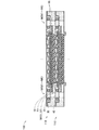
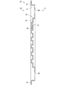
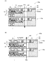
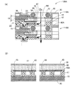
図1,図2は本発明の一実施例としての燃料電池の構成を示す概略図である。図1は、燃料電池100が組み立てられた状態を示す概略図であり、図2は、燃料電池100の各構成部を分解して示した概略図である。なお、図2では、単セル110の各構成部を一体的に組み付ける際に設けられる接着層60の図示が省略されている。
A. First embodiment:
1 and 2 are schematic views showing the structure of a fuel cell as an embodiment of the present invention. FIG. 1 is a schematic diagram illustrating a state in which the fuel cell 100 is assembled, and FIG. 2 is a schematic diagram illustrating the components of the fuel cell 100 in an exploded manner. In FIG. 2, the illustration of the adhesive layer 60 provided when the components of the single cell 110 are assembled together is omitted.

燃料電池100は、第1と第2の反応ガスとして水素と酸素の供給を受けて発電する固体高分子形燃料電池である。燃料電池100は、発電モジュールである単セル110が複数個積層されたスタック構造を有する。単セル110は、膜電極接合体10と、ガス拡散部材20と、第1と第2のセパレータ30,40と、ガス通路部材50と、を備える。   The fuel cell 100 is a polymer electrolyte fuel cell that generates power by receiving supply of hydrogen and oxygen as first and second reaction gases. The fuel cell 100 has a stack structure in which a plurality of single cells 110 that are power generation modules are stacked. The single cell 110 includes a membrane electrode assembly 10, a gas diffusion member 20, first and second separators 30 and 40, and a gas passage member 50.

膜電極接合体10は、電解質膜1の両面に第1と第2の電極2,3を配置した発電体である。単セル110では、膜電極接合体10が、第1と第2のセパレータ30,40に狭持される。第1と第2のセパレータ30,40は、金属板などの導電性を有する板状部材によって構成される。そして、第1と第2のセパレータ30,40は、プレス加工により、その外表面に、反応ガスや冷媒のための流路溝が形成されている。第1と第2のセパレータ30,40の流路溝の構成については後述する。   The membrane electrode assembly 10 is a power generator in which first and second electrodes 2 and 3 are arranged on both surfaces of the electrolyte membrane 1. In the single cell 110, the membrane electrode assembly 10 is held between the first and second separators 30 and 40. The 1st and 2nd separators 30 and 40 are comprised by the plate-shaped member which has electroconductivity, such as a metal plate. The first and second separators 30 and 40 are formed with flow channels for reaction gas and refrigerant on the outer surfaces thereof by press working. The configuration of the channel grooves of the first and second separators 30 and 40 will be described later.

ガス拡散部材20は、膜電極接合体10と、第2のセパレータ40との間に介挿される、導電性を有する多孔質な板状部材であり、酸素を、膜電極接合体10の第2の電極3の全体に拡散して行き渡らせるためのガス拡散流路として機能する。なお、本実施例の燃料電池100では、ガス拡散部材20は、その外周端部の位置が、第2の電極3の外周端部の位置と、ほぼ揃うように配置されている。本実施例におけるガス拡散部材20の詳細な構成については後述する。   The gas diffusion member 20 is a porous plate-like member having conductivity and interposed between the membrane electrode assembly 10 and the second separator 40, and oxygen is supplied to the second electrode of the membrane electrode assembly 10. It functions as a gas diffusion channel for diffusing and spreading over the entire electrode 3. In the fuel cell 100 of the present embodiment, the gas diffusion member 20 is arranged so that the position of the outer peripheral end thereof is substantially aligned with the position of the outer peripheral end of the second electrode 3. A detailed configuration of the gas diffusion member 20 in the present embodiment will be described later.

ここで、単セル110では、膜電極接合体10の外周全体に接着剤を配置して接着層60を設けることにより、膜電極接合体10と、第1と第2のセパレータ30,40とが、ガス拡散部材20を含めて一体化される(図1)。なお、接着層60は、単セル110において、流体の漏洩を防止するためのシール層として機能し、第1と第2のセパレータ30,40の間を電気的に絶縁する絶縁層としても機能する。単セル110における接着層60の具体的な構成については後述する。   Here, in the single cell 110, the membrane electrode assembly 10 and the first and second separators 30 and 40 are provided by disposing an adhesive on the entire outer periphery of the membrane electrode assembly 10 and providing the adhesive layer 60. The gas diffusion member 20 is integrated (FIG. 1). The adhesive layer 60 functions as a sealing layer for preventing fluid leakage in the single cell 110 and also functions as an insulating layer that electrically insulates between the first and second separators 30 and 40. . A specific configuration of the adhesive layer 60 in the single cell 110 will be described later.

また、単セル110には、反応ガスや冷媒のためのマニホールドMが、膜電極接合体10を囲む外周領域に、第1と第2のセパレータ30,40および接着層60を、厚み方向(積層方向)に貫通する貫通孔として形成されている。具体的に、マニホールドMとしては、水素の供給用および排出用マニホールドM1,M2、酸素の供給用および排出用マニホールドM3,M4、酸素の供給用および排出用マニホールドM5,M6が設けられる。各マニホールドM1〜M8の具体的な形成位置については後述する。   In the single cell 110, the manifold M for the reaction gas and the refrigerant is provided with the first and second separators 30 and 40 and the adhesive layer 60 in the thickness direction (lamination) in the outer peripheral region surrounding the membrane electrode assembly 10. It is formed as a through hole penetrating in the direction). Specifically, as the manifold M, hydrogen supply and discharge manifolds M1 and M2, oxygen supply and discharge manifolds M3 and M4, oxygen supply and discharge manifolds M5 and M6 are provided. Specific positions where the manifolds M1 to M8 are formed will be described later.

ガス通路部材50は、単セル110において、反応ガスのためのマニホールドMと、膜電極接合体10の発電領域(第1と第2の電極2,3)との間を連通するガス通路を構成する部材である。ガス通路部材50は、第1と第2のセパレータ30,40の間において、マニホールドMの近傍に配置される。単セル110では、ガス通路部材50として、水素用のガス通路部材51と、酸素用のガス通路部材52とが、それぞれの反応ガスのマニホールドM1〜M4に対応して配置される。各通路部材51,52の詳細な構成については後述する。   In the single cell 110, the gas passage member 50 forms a gas passage that communicates between the manifold M for the reaction gas and the power generation region (first and second electrodes 2 and 3) of the membrane electrode assembly 10. It is a member to do. The gas passage member 50 is disposed in the vicinity of the manifold M between the first and second separators 30 and 40. In the single cell 110, as the gas passage member 50, a gas passage member 51 for hydrogen and a gas passage member 52 for oxygen are arranged corresponding to the respective reaction gas manifolds M1 to M4. The detailed configuration of each of the passage members 51 and 52 will be described later.

さらに、燃料電池100では、各単セル110の間に、マニホールドMからの流体の漏洩を防止するためのシール部材70が配置される。シール部材70は、例えば、略円形断面の無端枠状の樹脂部材によって構成できる。なお、シール部材70によって形成されるシールラインについては後述する。   Further, in the fuel cell 100, a seal member 70 for preventing fluid leakage from the manifold M is disposed between the single cells 110. The seal member 70 can be constituted by, for example, an endless frame-shaped resin member having a substantially circular cross section. The seal line formed by the seal member 70 will be described later.

このように、本実施例の燃料電池100では、接着層60によって一体的に構成された単セル110が、シール部材70を狭持した状態で積層されている。この構成により、本実施例の燃料電池100は、複数の単セル110のうち、一部の単セル110のみに不具合が生じた場合であっても、当該一部の単セル110と、シール部材70の交換によって復旧させることが可能である。また、本実施例の燃料電池100であれば、以下に説明する構成を有することにより、小型化され、劣化などの不具合の発生が抑制されている。   As described above, in the fuel cell 100 according to the present embodiment, the single cells 110 integrally formed by the adhesive layer 60 are stacked with the seal member 70 sandwiched therebetween. With this configuration, the fuel cell 100 according to the present embodiment is configured such that, even when a failure occurs only in some of the single cells 110 among the plurality of single cells 110, the partial cells 110 and the seal member It is possible to recover by exchanging 70. Moreover, if it is the fuel cell 100 of a present Example, it has reduced the size by having the structure demonstrated below, and generation | occurrence | production of malfunctions, such as deterioration, is suppressed.

図3は、膜電極接合体10の詳細な構成を説明するための概略図である。電解質膜1は、湿潤状態で良好なプロトン伝導性を示す高分子薄膜である。電解質膜1としては、例えば、フッ素樹脂系のイオン交換膜を用いることができる。第1と第2の電極2,3はそれぞれ、触媒層2c,3cと、ガス拡散層2g,3gとが積層された構成を有する。   FIG. 3 is a schematic diagram for explaining a detailed configuration of the membrane electrode assembly 10. The electrolyte membrane 1 is a polymer thin film that exhibits good proton conductivity in a wet state. As the electrolyte membrane 1, for example, a fluororesin-based ion exchange membrane can be used. Each of the first and second electrodes 2 and 3 has a structure in which catalyst layers 2c and 3c and gas diffusion layers 2g and 3g are laminated.

触媒層2c,3cは、燃料電池反応を促進するための触媒(例えば白金(Pt)など)が担持された層である。触媒層2c,3cは、触媒担持カーボンを、電解質膜1の外表面に付着させることにより形成することができる。   The catalyst layers 2c and 3c are layers on which a catalyst (for example, platinum (Pt)) for promoting a fuel cell reaction is supported. The catalyst layers 2 c and 3 c can be formed by attaching catalyst-supporting carbon to the outer surface of the electrolyte membrane 1.

ガス拡散層2g,3gは、第1または第2の電極2,3の全体に反応ガスを拡散させて行き渡らせるための層である。ガス拡散層2g,3gは、炭素繊維や黒鉛繊維など、導電性およびガス透過性・ガス拡散性を有する多孔質の繊維基材を、触媒層2c,3cの上に重ねて配置し、ホットプレスすることにより形成することができる。   The gas diffusion layers 2g and 3g are layers for diffusing and spreading the reaction gas over the entire first or second electrode 2 or 3. The gas diffusion layers 2g and 3g are made by placing a porous fiber base material having conductivity, gas permeability and gas diffusion properties such as carbon fiber and graphite fiber on the catalyst layers 2c and 3c, and hot pressing. Can be formed.

なお、本実施例の燃料電池100では、膜電極接合体10の第1の電極2が、第1の反応ガスである水素の供給を受けてアノードとして機能し、第2の電極3が、第2の反応ガスである酸素の供給を受けてカソードとして機能する。以後、本明細書では、第1と第2の電極2,3をそれぞれ「アノード2」および「カソード3」とも呼ぶ。   In the fuel cell 100 of the present embodiment, the first electrode 2 of the membrane electrode assembly 10 receives the supply of hydrogen as the first reaction gas and functions as an anode, and the second electrode 3 It receives the supply of oxygen as the reaction gas 2 and functions as a cathode. Hereinafter, in the present specification, the first and second electrodes 2 and 3 are also referred to as “anode 2” and “cathode 3”, respectively.

ここで、本実施例の膜電極接合体10では、アノード2とカソード3とが異なるサイズで構成されている。具体的には、アノード2は、電解質膜1とほぼ同じサイズで構成され、アノード2の外周端部と電解質膜1の外周端部とがほぼ揃った状態となっているのに対し、カソード3は、電解質膜1よりも小さいサイズで構成され、カソード3の外周端部は、電解質膜1の外周端部より内側に位置している。   Here, in the membrane electrode assembly 10 of the present embodiment, the anode 2 and the cathode 3 are configured in different sizes. Specifically, the anode 2 is configured to have substantially the same size as the electrolyte membrane 1, and the outer peripheral end portion of the anode 2 and the outer peripheral end portion of the electrolyte membrane 1 are substantially aligned, whereas the cathode 3 Is configured to be smaller than the electrolyte membrane 1, and the outer peripheral end of the cathode 3 is located inside the outer peripheral end of the electrolyte membrane 1.

即ち、膜電極接合体10では、カソード3の外周において電解質膜1の外表面が露出しており、カソード3の外周端部と電解質膜1の外表面とで、段差部4が形成される。こうした構成により、燃料電池100では、アノード2の端部とカソード3の端部とを離間させ、反応ガスが電気化学反応に用いられることなく、供給された側とは反対の側の電極の側へと移動してしまうクロスリークを抑制する。なお、本実施例の燃料電池100では、膜電極接合体10に、この段差部4が設けられていることにより、後述する第1の接着部61の形成が容易化されている。   That is, in the membrane electrode assembly 10, the outer surface of the electrolyte membrane 1 is exposed on the outer periphery of the cathode 3, and a step portion 4 is formed between the outer peripheral end portion of the cathode 3 and the outer surface of the electrolyte membrane 1. With this configuration, in the fuel cell 100, the end of the anode 2 and the end of the cathode 3 are separated from each other, and the reaction gas is not used for the electrochemical reaction, and the side of the electrode opposite to the supplied side is used. Suppresses cross leaks that move to In the fuel cell 100 of the present embodiment, the formation of the first bonding portion 61 described later is facilitated by providing the stepped portion 4 in the membrane electrode assembly 10.

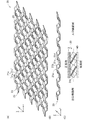
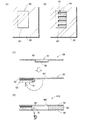
図4(A)〜(C)は、本実施例におけるガス拡散部材20の構成を説明するための概略図である。図4(A)は、ガス拡散部材20の全体を示す概略斜視図であり、図4(B)は、ガス拡散部材20の構成要素である波板部23を示す概略斜視図である。なお、図4(A),(B)にはそれぞれ、三次元方向を示す矢印x,y,zが互いに対応するように図示されている。図4(C)は、単セル110にガス拡散部材20が組み付けられたときの状態を示す概略断面図である。図4(C)では、紙面右側を酸素供給用マニホールドM3側とし、紙面左側を酸素排出用マニホールドM4側として図示してある。   4A to 4C are schematic views for explaining the configuration of the gas diffusion member 20 in the present embodiment. 4A is a schematic perspective view showing the entire gas diffusion member 20, and FIG. 4B is a schematic perspective view showing a corrugated plate portion 23 that is a component of the gas diffusion member 20. In FIGS. 4A and 4B, arrows x, y, and z indicating three-dimensional directions are shown to correspond to each other. FIG. 4C is a schematic cross-sectional view showing a state when the gas diffusion member 20 is assembled to the single cell 110. In FIG. 4C, the right side of the drawing is illustrated as the oxygen supply manifold M3 side, and the left side of the drawing is illustrated as the oxygen discharge manifold M4 side.

本実施例の燃料電池100では、ガス拡散部材20として、1枚の金属板を、切削加工および折り加工により網目状に加工した、いわゆるエキスパンドメタルを用いている。このガス拡散部材20は、複数の波板部23がz方向に並列に配置された構成を有する(図4(A))。各波板部23は、互いに連続する第1ないし第4の壁部21a,21b,21c,21dが繰り返しx方向に順に配置された構成を有する(図4(B))。   In the fuel cell 100 of the present embodiment, a so-called expanded metal obtained by processing a single metal plate into a mesh shape by cutting and folding is used as the gas diffusion member 20. The gas diffusion member 20 has a configuration in which a plurality of corrugated plate portions 23 are arranged in parallel in the z direction (FIG. 4A). Each corrugated plate portion 23 has a configuration in which first to fourth wall portions 21a, 21b, 21c, and 21d that are continuous with each other are repeatedly arranged in order in the x direction (FIG. 4B).

波板部23では、第1と第3の壁部21a,21cは、それらの壁面が、互いに上下にオフセットされるとともに略平行となるように配列されている。また、第1と第3の壁部21a,21cを連結する第2と第4の壁部21b、21dは、その壁面が第1と第3の壁部21a,21cの壁面に対して斜面を構成している。   In the corrugated plate portion 23, the first and third wall portions 21a and 21c are arranged such that their wall surfaces are offset in the vertical direction and are substantially parallel to each other. The second and fourth wall portions 21b and 21d connecting the first and third wall portions 21a and 21c are inclined with respect to the wall surfaces of the first and third wall portions 21a and 21c. It is composed.

そして、互いに隣り合って配列された波板部23の、それぞれの第1の壁部21aと第3の壁部21cとは、互いに連結されて、連続する壁部21e(以後、「連結壁部21e」とも呼ぶ)を構成する(図4(A))。これによって、ガス拡散部材20では、隣り合う波板部23の間に、各壁部21a〜21dの壁面を辺とする略六角形の貫通孔25が規則的に配列された状態で形成される。   The first wall portion 21a and the third wall portion 21c of the corrugated plate portions 23 arranged adjacent to each other are connected to each other to form a continuous wall portion 21e (hereinafter referred to as “connection wall portion”). 21e ") (FIG. 4A). As a result, in the gas diffusion member 20, between the adjacent corrugated plate portions 23, the substantially hexagonal through holes 25 having the side surfaces of the wall portions 21 a to 21 d as sides are formed in a regularly arranged state. .

単セル110では、ガス拡散部材20は、連結壁部21eの互いに対向し合う2辺がそれぞれ、膜電極接合体10のカソード3の外表面と、第2のセパレータ40の外表面とに接するように配置される(図4(C))。そして、連結壁部21eの壁面は、カソード3の外表面に対して、酸素供給用マニホールドM3側(紙面右側)が鋭角となる傾斜角を形成するように配置される。ガス拡散部材20に流入した酸素は、各貫通孔25をすり抜けて、酸素の供給側から酸素の排出側へと流れつつ、カソード3の電極面に沿った方向に拡散する。   In the single cell 110, the gas diffusion member 20 is configured such that two opposite sides of the connecting wall portion 21 e are in contact with the outer surface of the cathode 3 of the membrane electrode assembly 10 and the outer surface of the second separator 40, respectively. (FIG. 4C). The wall surface of the connecting wall portion 21e is disposed so as to form an inclination angle with respect to the outer surface of the cathode 3 so that the oxygen supply manifold M3 side (the right side in the drawing) is an acute angle. The oxygen flowing into the gas diffusion member 20 passes through each through-hole 25 and diffuses in the direction along the electrode surface of the cathode 3 while flowing from the oxygen supply side to the oxygen discharge side.

なお、本明細書では、便宜上、ガス拡散部材20を単セル110に組み付けたときに、酸素用のマニホールドM3,M4と対向する、ガス拡散部材20の側端部側をそれぞれ、「ガス拡散部材20の入口側面側/出口側面側」と呼ぶ。また、ガス拡散部材20のカソード3の電極面と対向し合う側を「ガス拡散部材20の正面側」と呼び、第2のセパレータ40の外表面と対向し合う側を「ガス拡散部材20の背面側」と呼ぶ。   In this specification, for convenience, when the gas diffusion member 20 is assembled to the single cell 110, the side end portions of the gas diffusion member 20 that face the oxygen manifolds M3 and M4 are respectively referred to as “gas diffusion member”. 20 inlet side surfaces / outlet side surfaces ”. The side of the gas diffusion member 20 facing the electrode surface of the cathode 3 is referred to as “the front side of the gas diffusion member 20”, and the side facing the outer surface of the second separator 40 is “of the gas diffusion member 20. Called “back side”.

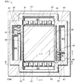
図5,図6は、第1のセパレータ30の構成を説明するための概略図である。ここで、第1のセパレータ30において、単セル110を構成したときに、膜電極接合体10が配置される側の面を「第1の面S1」と呼び、その反対側の面を「第2の面S2」と呼ぶ。図5には、第1のセパレータ30における第2の面S2側の構成を図示してある。図6には、図5に示すA−A切断における第1のセパレータ30の概略断面を図示してある。   5 and 6 are schematic views for explaining the configuration of the first separator 30. FIG. Here, in the first separator 30, when the single cell 110 is configured, the surface on which the membrane electrode assembly 10 is disposed is referred to as a “first surface S 1”, and the surface on the opposite side is referred to as the “first surface”. 2 side S2 ". FIG. 5 illustrates the configuration of the first separator 30 on the second surface S2 side. FIG. 6 shows a schematic cross section of the first separator 30 taken along the line AA shown in FIG.

なお、図5には、単セル110を構成したときに膜電極接合体10が配置される領域を示す膜電極接合体10の外周輪郭投影線MPLを一点鎖線で図示してある。また、図5には、燃料電池100を構成したときに、シール部材70(図1,図2)が配置されて形成されるシールラインSLを二点鎖線で図示してある。   In FIG. 5, an outer peripheral contour projection line MPL of the membrane electrode assembly 10 indicating a region where the membrane electrode assembly 10 is arranged when the single cell 110 is configured is illustrated by a one-dot chain line. Further, in FIG. 5, a seal line SL formed by arranging the seal member 70 (FIGS. 1 and 2) when the fuel cell 100 is configured is illustrated by a two-dot chain line.

第1のセパレータ30には、マニホールドM1〜M6を構成するための貫通孔が、膜電極接合体10の外周を囲むように配列して形成されている。なお、本明細書では、以後、燃料電池においてマニホールドを構成するために各構成部に設けられた貫通孔や流路についても、単に「マニホールド」と呼び、マニホールドと同様な符号を付すものとする。第1のセパレータ30において、各マニホールドM1〜M6は、以下のように配列されている。   In the first separator 30, through holes for configuring the manifolds M <b> 1 to M <b> 6 are formed so as to surround the outer periphery of the membrane electrode assembly 10. In the present specification, hereinafter, the through holes and flow paths provided in the respective components for constituting the manifold in the fuel cell are also simply referred to as “manifold” and are denoted by the same reference numerals as the manifold. . In the first separator 30, the manifolds M1 to M6 are arranged as follows.

水素と冷媒のそれぞれの供給用マニホールドM1,M5は互いに隣り合うように配列され、水素と冷媒のそれぞれの排出用マニホールドM2,M6も互いに隣り合うように配列されている。そして、水素と冷媒の供給用マニホールドM1,M5の組と、水素と冷媒の排出用マニホールドM2,M6の組とはそれぞれ、膜電極接合体10の互いに対向する外周二辺に沿って配列されている。酸素の供給用及び排出用マニホールドM3,M4はそれぞれ、膜電極接合体10の残余の外周二辺に沿って配列されている。   The supply manifolds M1 and M5 for hydrogen and refrigerant are arranged adjacent to each other, and the discharge manifolds M2 and M6 for hydrogen and refrigerant are also arranged adjacent to each other. A set of hydrogen and refrigerant supply manifolds M1 and M5 and a set of hydrogen and refrigerant discharge manifolds M2 and M6 are arranged along two outer peripheral sides of the membrane electrode assembly 10 facing each other. Yes. The oxygen supply and discharge manifolds M3 and M4 are arranged along the remaining two outer peripheral sides of the membrane electrode assembly 10, respectively.

なお、水素の供給用マニホールドM1と排出用マニホールドM2とは、膜電極接合体10の発電領域を挟んで互いに対角する位置に形成されている。また、酸素用のマニホールドM3,M4は、対応する膜電極接合体10の外周二辺と同程度の幅を有する長方形形状で形成されている。各マニホールドM1〜M6の開口形状や配列は、他の構成であっても良い。   The hydrogen supply manifold M1 and the discharge manifold M2 are formed at positions diagonal to each other across the power generation region of the membrane electrode assembly 10. The oxygen manifolds M3 and M4 are formed in a rectangular shape having the same width as the two outer peripheral sides of the corresponding membrane electrode assembly 10. The opening shape and arrangement of each manifold M1 to M6 may be other configurations.

ここで、第1のセパレータ30では、各マニホールドM1〜M6の形成領域が、第1のセパレータ30の外周端部32の外表面よりも低くなるように、第1の面S1側(図6の紙面右側)に窪み、シール部材70を配置するためのシール部材配置部31を形成している。また、第1のセパレータ30では、シール部材配置部31に囲まれた中央の領域が、シール部材配置部31よりも第2の面S2側に突出し、アノード2を収容して配置するためのアノード配置部33を形成している。   Here, in the 1st separator 30, the 1st surface S1 side (of FIG. 6) is formed so that the formation area of each manifold M1-M6 may become lower than the outer surface of the outer peripheral edge part 32 of the 1st separator 30. A seal member placement portion 31 for placing the seal member 70 is formed on the right side of the drawing. Further, in the first separator 30, the central region surrounded by the seal member arrangement portion 31 protrudes to the second surface S 2 side from the seal member arrangement portion 31, and an anode for accommodating and arranging the anode 2. An arrangement portion 33 is formed.

さらに、アノード配置部33の第1の面S1側には、水素のための複数の並列な流路溝35(以後、「水素流路溝35」と呼ぶ)が、アノード配置部33の板面を凹凸させることにより形成されている。水素流路溝35は、水素供給用マニホールドM1側(図5の紙面左側)から水素排出用マニホールドM2側(図5の紙面右側)に向かって延びる直線状の溝として形成されている。   Further, on the first surface S 1 side of the anode arrangement portion 33, a plurality of parallel flow channel grooves 35 for hydrogen (hereinafter referred to as “hydrogen flow channel grooves 35”) are provided on the plate surface of the anode arrangement portion 33. It is formed by uneven | corrugated. The hydrogen channel groove 35 is formed as a linear groove extending from the hydrogen supply manifold M1 side (left side of the drawing in FIG. 5) toward the hydrogen discharge manifold M2 side (right side of the drawing in FIG. 5).

なお、水素流路溝35の反対側の面(第2の面S2側の面)は、第1のセパレータ30の外周端部32の外表面と同一の仮想平面上に存在しており、単セル110を構成したときに、第2のセパレータ40の板面と接触する。そして、第1のセパレータ30の第1の面S1側に水素流路溝35を形成したことにより第2の面S2側に形成される複数の並列な溝36は、燃料電池100を構成したときに冷媒のための流路として機能する。   Note that the surface on the opposite side of the hydrogen flow channel 35 (the surface on the second surface S2 side) exists on the same virtual plane as the outer surface of the outer peripheral end portion 32 of the first separator 30, and When the cell 110 is configured, it contacts the plate surface of the second separator 40. When the hydrogen flow channel 35 is formed on the first surface S1 side of the first separator 30 and the plurality of parallel grooves 36 formed on the second surface S2 side constitute the fuel cell 100. It functions as a flow path for the refrigerant.

第1のセパレータ30のシール部材配置部31には、前記したとおり、シール部材70(図1,図2)が配置される。燃料電池100が構成されたときに、シール部材70は、反応ガスのマニホールドM1〜M4のそれぞれを囲むように配置される。そして、シール部材70は、冷媒用のマニホールドM4,M5とアノード配置部33とを囲むように配置される。これによって、各単セル110同士の間には冷媒の流路空間が形成される。   As described above, the seal member 70 (FIGS. 1 and 2) is disposed in the seal member placement portion 31 of the first separator 30. When the fuel cell 100 is configured, the seal member 70 is disposed so as to surround each of the reactant gas manifolds M1 to M4. The seal member 70 is arranged so as to surround the refrigerant manifolds M4 and M5 and the anode arrangement portion 33. Thus, a refrigerant flow space is formed between the single cells 110.

このように、本実施例の燃料電池100では、シール部材70の配置空間を、第1のセパレータ30を窪ませて形成している。従って、シール部材70を配置することにより、積層方向に燃料電池100が大型化してしまうことが抑制されている。なお、シール部材70によるシール性を向上させるために、シール部材配置部31は、シールラインSLが同一の仮想平面上に存在するように平坦に形成されていることが好ましい。   Thus, in the fuel cell 100 of the present embodiment, the arrangement space of the seal member 70 is formed by recessing the first separator 30. Therefore, disposing the seal member 70 prevents the fuel cell 100 from becoming large in the stacking direction. In addition, in order to improve the sealing performance by the sealing member 70, it is preferable that the sealing member arrangement part 31 is formed flat so that the sealing line SL exists on the same virtual plane.

図7,図8は、第2のセパレータ40の構成を説明するための概略図である。ここで、第1のセパレータ30と同様に、第2のセパレータ40において、単セル110を構成したときに膜電極接合体10が配置される側の面を「第1の面S1」と呼び、その反対側の面を「第2の面S2」と呼ぶ。   7 and 8 are schematic views for explaining the configuration of the second separator 40. FIG. Here, similarly to the first separator 30, in the second separator 40, the surface on which the membrane electrode assembly 10 is arranged when the single cell 110 is configured is referred to as “first surface S <b> 1”. The opposite surface is referred to as “second surface S2”.

図7には、第2のセパレータ40における第1の面S1側の構成を図示してある。図8には、図7に示すA−A切断における第2のセパレータ40の概略断面を図示してある。なお、図7には、ガス拡散部材20が配置される領域EMAを一点鎖線で図示してあり、ガス通路部材50である水素通路部材51および酸素通路部材52のそれぞれが配置される領域PMA1,PMA2を二点鎖線で図示してある。   FIG. 7 illustrates a configuration of the second separator 40 on the first surface S1 side. FIG. 8 shows a schematic cross section of the second separator 40 taken along the line AA shown in FIG. In FIG. 7, a region EMA where the gas diffusion member 20 is arranged is shown by a one-dot chain line, and a region PMA1, where each of the hydrogen passage member 51 and the oxygen passage member 52 as the gas passage member 50 is arranged. PMA2 is illustrated by a two-dot chain line.

第2のセパレータ40には、反応ガスおよび冷媒のためのマニホールドM1〜M6が、第1のセパレータ30と同様な構成で形成されている。また、第2のセパレータ40の第1の面S1側には、酸素用のマニホールドM3,M4のそれぞれに並列に延びる2本の溝部41が、第2のセパレータ40の板面を凹凸させることにより形成されている。即ち、第2のセパレータ40の第2の面S2側では、流路溝41の形成部位が突出している。   In the second separator 40, manifolds M <b> 1 to M <b> 6 for reaction gas and refrigerant are formed in the same configuration as the first separator 30. In addition, on the first surface S1 side of the second separator 40, two groove portions 41 extending in parallel with the oxygen manifolds M3 and M4 respectively make the plate surface of the second separator 40 uneven. Is formed. That is, on the second surface S2 side of the second separator 40, the formation site of the flow channel 41 is projected.

これらの溝部41は、酸素用マニホールドM3,M4と平行な、ガス拡散部材20の配置領域EMAの外周二辺と重なる位置に形成されており、ガス拡散部材20に酸素を流入させるためのガス流路溝として機能する。以後、第2のセパレータ40に形成された溝部41を「酸素流路溝41」とも呼ぶ。   These groove portions 41 are formed at positions that are parallel to the oxygen manifolds M3 and M4 and overlap the two outer peripheral sides of the arrangement area EMA of the gas diffusion member 20, and a gas flow for allowing oxygen to flow into the gas diffusion member 20 It functions as a road groove. Hereinafter, the groove portion 41 formed in the second separator 40 is also referred to as an “oxygen channel groove 41”.

ここで、第2のセパレータ40の第1の面S1側には、ガス通路部材50である水素通路部材51と酸素通路部材52とが配置される。水素通路部材51は、領域PMA1として図示した位置、即ち、水素用のマニホールドM1,M2と膜電極接合体10との間であって、水素用のマニホールドM1,M2の膜電極接合体10側の端部に隣接する位置に配置される。   Here, on the first surface S1 side of the second separator 40, a hydrogen passage member 51 and an oxygen passage member 52, which are gas passage members 50, are arranged. The hydrogen passage member 51 is located at the position illustrated as the region PMA1, that is, between the hydrogen manifolds M1 and M2 and the membrane electrode assembly 10 and on the membrane electrode assembly 10 side of the hydrogen manifolds M1 and M2. It arrange | positions in the position adjacent to an edge part.

また、酸素通路部材52は、領域PMA2として図示した位置、即ち、酸素用のマニホールドM3,M4と膜電極接合体10との間の領域に配置される。なお、酸素通路部材52の膜電極接合体10側の一方の端部は、酸素用のマニホールドM3,M4のそれぞれの端部に隣接して配置され、他方の端部は、酸素流路溝41に重なるように配置される。   The oxygen passage member 52 is disposed at a position illustrated as the region PMA2, that is, a region between the oxygen manifolds M3 and M4 and the membrane electrode assembly 10. One end portion of the oxygen passage member 52 on the membrane electrode assembly 10 side is disposed adjacent to each end portion of the oxygen manifolds M3 and M4, and the other end portion is the oxygen flow channel groove 41. It is arranged to overlap.

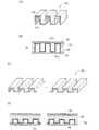
図9は、ガス通路部材50の構成を説明するための概略図である。図9(A)は、水素通路部材51の構成を示す概略斜視図であり、図9(B)は、水素通路部材51が単セル110において第1と第2のセパレータ30,40に狭持された状態を示す概略断面図である。また、図9(C)は、酸素通路部材52の構成を示す概略斜視図であり、図9(D)は、酸素通路部材52が単セル110において第1と第2のセパレータ30,40に狭持された状態を示す概略断面図である。なお、図9(B),(D)の概略断面図はそれぞれ、図8に示すX−X切断およびY−Y切断に相当する切断面を示している。   FIG. 9 is a schematic view for explaining the configuration of the gas passage member 50. FIG. 9A is a schematic perspective view showing the configuration of the hydrogen passage member 51, and FIG. 9B shows that the hydrogen passage member 51 is held between the first and second separators 30 and 40 in the single cell 110. It is a schematic sectional drawing which shows the state made. 9C is a schematic perspective view showing the configuration of the oxygen passage member 52. FIG. 9D shows the oxygen passage member 52 connected to the first and second separators 30 and 40 in the single cell 110. FIG. It is a schematic sectional drawing which shows the state pinched. 9B and 9D show cross sections corresponding to the XX cut and the YY cut shown in FIG. 8, respectively.

水素通路部材51および酸素通路部材52はそれぞれ、板状部材をプレス加工して、波上に凹凸させることにより形成されている(図9(A),(C))。水素通路部材51および酸素通路部材52は、単セル110に組み付けられたときに、各マニホールドM1〜M4の端部において、貫通方向に沿って突出する壁部53を形成する(図9(B),(D))。そして、各マニホールドM1〜M4と膜電極接合体10との間の複数の並列なガス通路を形成する。   Each of the hydrogen passage member 51 and the oxygen passage member 52 is formed by pressing a plate-like member so as to be uneven on the wave (FIGS. 9A and 9C). The hydrogen passage member 51 and the oxygen passage member 52 form a wall portion 53 protruding along the penetration direction at the end of each of the manifolds M1 to M4 when assembled to the single cell 110 (FIG. 9B). , (D)). A plurality of parallel gas passages are formed between the manifolds M1 to M4 and the membrane electrode assembly 10.

ところで、水素通路部材51は、その上面51tと底面51bとが第1と第2のセパレータ30,40の両方に直接的に接触して配置される(図9(B))。従って、水素通路部材51は、第1と第2のセパレータ30,40の間の短絡を防止するために、非導電性部材で構成されることが好ましい。あるいは、水素通路部材51は、絶縁コーティングされた導電性板状部材(例えば金属板)によって形成されるものとしても良い。また、水素通路部材51を導電性板状部材で構成し、水素通路部材51と第1または第2のセパレータ30,40との間に絶縁部材を介挿・配置するものとしても良い。   By the way, the hydrogen passage member 51 is arranged such that the upper surface 51t and the bottom surface 51b thereof are in direct contact with both the first and second separators 30 and 40 (FIG. 9B). Therefore, the hydrogen passage member 51 is preferably composed of a non-conductive member in order to prevent a short circuit between the first and second separators 30 and 40. Alternatively, the hydrogen passage member 51 may be formed by a conductive plate member (for example, a metal plate) that is coated with insulation. Alternatively, the hydrogen passage member 51 may be formed of a conductive plate-like member, and an insulating member may be interposed and disposed between the hydrogen passage member 51 and the first or second separator 30 or 40.

一方、酸素通路部材52は、第2のセパレータ40とは直接的に接触するように配置されるが、酸素通路部材52と第1のセパレータ30との間には接着層60が形成される(図9(D))。従って、酸素通路部材52は、導電性部材によって構成されるものとしても良い。この場合には、接着層60によって、第1と第2のセパレータ30,40の間の短絡が防止される。なお、酸素通路部材52は、水素通路部材51と同様な非導電性部材によって構成されるものとしても良い。   On the other hand, the oxygen passage member 52 is disposed so as to be in direct contact with the second separator 40, but an adhesive layer 60 is formed between the oxygen passage member 52 and the first separator 30 ( FIG. 9D). Therefore, the oxygen passage member 52 may be configured by a conductive member. In this case, the adhesive layer 60 prevents a short circuit between the first and second separators 30 and 40. The oxygen passage member 52 may be formed of a non-conductive member similar to the hydrogen passage member 51.

このように、本実施例の燃料電池100では、各単セル110における反応ガスのマニホールドM1〜M4の端部にガス通路部材50が配置されている。このガス通路部材50によって、各マニホールドM1〜M4の端部には、各マニホールドM1〜M4の貫通方向に沿って突出する通路壁部53が形成され、その通路壁部53が各マニホールドM1〜M4の端部を補強する支持部材として機能する。そのため、単セル110が薄型化された場合であっても、各マニホールドM1〜M4の端部の変形に起因する、反応ガスの通路入口/通路出口の閉塞や、第1と第2のセパレータ30,40同士の短絡の発生が抑制される。   Thus, in the fuel cell 100 of the present embodiment, the gas passage member 50 is disposed at the end of the reaction gas manifolds M1 to M4 in each unit cell 110. By this gas passage member 50, a passage wall portion 53 is formed at the end of each of the manifolds M1 to M4 so as to protrude along the penetrating direction of each of the manifolds M1 to M4. It functions as a support member that reinforces the end of the. Therefore, even when the single cell 110 is thinned, the reaction gas passage inlet / passage outlet is blocked or the first and second separators 30 are caused by the deformation of the ends of the manifolds M1 to M4. , 40 is prevented from being short-circuited.

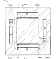
図10は、単セル110に形成される接着層60の形成領域を説明するための模式図である。図10には、模式的に線画として図示された第2のセパレータ40の第1の面S1に、接着層60が形成される領域をハッチングを付して示してある。ここで、接着層60は、それぞれ接着領域と機能とが異なる第1〜第3の接着部61〜63を有する。図10では、第1〜第3の接着部61〜63の形成領域をそれぞれ異なる種類のハッチングを付して図示してある。   FIG. 10 is a schematic diagram for explaining a formation region of the adhesive layer 60 formed in the single cell 110. In FIG. 10, a region where the adhesive layer 60 is formed is hatched on the first surface S <b> 1 of the second separator 40 schematically illustrated as a line drawing. Here, the adhesive layer 60 includes first to third adhesive portions 61 to 63 having different adhesive regions and functions. In FIG. 10, the formation regions of the first to third adhesive portions 61 to 63 are illustrated with different types of hatching.

なお、図10には、図7と同様に、ガス通路部材50の配置領域PMA1,PMA2を二点鎖線で図示し、ガス拡散部材20の配置領域EMAを一点鎖線で図示してある。さらに、図10には、膜電極接合体10の外周輪郭投影線MPLを一点鎖線で図示してある。   In FIG. 10, similarly to FIG. 7, the arrangement areas PMA1 and PMA2 of the gas passage member 50 are illustrated by two-dot chain lines, and the arrangement area EMA of the gas diffusion member 20 is illustrated by one-dot chain lines. Further, in FIG. 10, the outer peripheral contour projection line MPL of the membrane electrode assembly 10 is illustrated by a one-dot chain line.

接着層60のうち、第1の接着部61は、水素のマニホールドM1,M2とアノード2との間に形成される水素通路の一部を構成する部位である。第1の接着層61は、水素がカソード3へと流入することを抑制するとともに、膜電極接合体10と第2のセパレータ40とを接着する。第1の接着部61は、ガス拡散部材20の配置領域EMAの外周端と、膜電極接合体10の外周輪郭投影線MPLとの間であって、第1のセパレータ30に設けられた水素流路溝35の入口端部および出口端部が配置される領域に形成される。   In the adhesive layer 60, the first adhesive portion 61 is a part constituting a part of a hydrogen passage formed between the hydrogen manifolds M 1 and M 2 and the anode 2. The first adhesive layer 61 prevents hydrogen from flowing into the cathode 3 and bonds the membrane electrode assembly 10 and the second separator 40 together. The first bonding portion 61 is located between the outer peripheral edge of the arrangement area EMA of the gas diffusion member 20 and the outer peripheral contour projection line MPL of the membrane electrode assembly 10, and the hydrogen flow provided in the first separator 30 It is formed in a region where the inlet end and the outlet end of the channel groove 35 are arranged.

第2の接着部62は、酸素のマニホールドM3,M4とカソード3との間に形成される酸素通路に酸素が流入することを抑制するとともに、膜電極接合体10と第1のセパレータ30とを接着する部位である。第2の接着部62は、酸素通路部材52の配置領域PMA2において、酸素通路部材52と、第1のセパレータ30と、膜電極接合体10の端部とを接着するように形成される。   The second bonding portion 62 suppresses oxygen from flowing into an oxygen passage formed between the oxygen manifolds M3 and M4 and the cathode 3, and connects the membrane electrode assembly 10 and the first separator 30 together. This is the part to be bonded. The second bonding portion 62 is formed so as to bond the oxygen passage member 52, the first separator 30, and the end portion of the membrane electrode assembly 10 in the arrangement region PMA2 of the oxygen passage member 52.

第3の接着部63は、第1と第2のセパレータ30,40を互いに接着するとともに、単セル110の外部への流体の漏洩を防止するとともに、膜電極接合体10の端部においてクロスリークが発生することを抑制する部位である。第3の接着部63は、第1と第2の接着部61,62の形成領域と、水素通路部材51の配置領域PMA1を除く各マニホールドM1〜M6の外周の領域に形成される。   The third bonding portion 63 bonds the first and second separators 30 and 40 to each other, prevents leakage of fluid to the outside of the unit cell 110, and cross-leaks at the end of the membrane electrode assembly 10. It is a site | part which suppresses generating. The third adhesive portion 63 is formed in the outer peripheral regions of the manifolds M1 to M6 excluding the formation region of the first and second adhesive portions 61 and 62 and the arrangement region PMA1 of the hydrogen passage member 51.

なお、第1の接着部61と第3の接着部63との間には、水素通路部材51の開口部と、第1のセパレータ30の水素流路溝35とを連結する通路を形成するための空隙部65が形成されている。また、第3の接着部63は、膜電極接合体10の四隅の表面を被覆するように形成されており、水素の流路と酸素の流路とを分離する。   Note that a passage connecting the opening of the hydrogen passage member 51 and the hydrogen flow channel groove 35 of the first separator 30 is formed between the first adhesive portion 61 and the third adhesive portion 63. The gap portion 65 is formed. The third bonding portion 63 is formed so as to cover the surfaces of the four corners of the membrane electrode assembly 10 and separates the hydrogen flow path and the oxygen flow path.

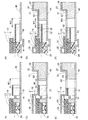
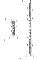
図11(A),(B)は、燃料電池100における水素の流れを説明するための模式図である。図11(A),(B)にはそれぞれ、図10に示すA−A切断およびB−B切断に相当する切断面における燃料電池100の概略断面と、水素の流れを示す矢印とを図示してある。なお、水素供給用マニホールドM1および水素排出用マニホールドM2における水素の流れは、図11(A),(B)に図示された方向とは反対の方向であっても良い。   FIGS. 11A and 11B are schematic diagrams for explaining the flow of hydrogen in the fuel cell 100. FIG. FIGS. 11A and 11B respectively show a schematic cross section of the fuel cell 100 and an arrow indicating the flow of hydrogen at a cut surface corresponding to the AA cut and the BB cut shown in FIG. It is. The hydrogen flow in the hydrogen supply manifold M1 and the hydrogen discharge manifold M2 may be in a direction opposite to the direction shown in FIGS.

水素供給用マニホールドM1に供給された水素は、各単セル110の水素通路部材51によって形成された水素通路へと分岐流入し、水素通路部材51から接着層60における空隙部65へと流れる(図11(A))。そして、水素は、膜電極接合体10のカソード3及びガス拡散部材20の端部を閉塞するように形成された第1の接着部61の外表面に沿って流れ、第1のセパレータ30に設けられた水素流路溝35に流入する。   The hydrogen supplied to the hydrogen supply manifold M1 branches and flows into the hydrogen passage formed by the hydrogen passage member 51 of each unit cell 110, and flows from the hydrogen passage member 51 to the gap 65 in the adhesive layer 60 (see FIG. 11 (A)). Then, hydrogen flows along the outer surface of the first bonding portion 61 formed so as to close the cathode 3 of the membrane electrode assembly 10 and the end portion of the gas diffusion member 20, and is provided in the first separator 30. It flows into the hydrogen channel groove 35 formed.

水素は、水素流路溝35を介して膜電極接合体10のアノード2へと流れ、発電反応に用いられる。発電反応に用いられることのなかった水素を含む排ガスは、水素流路溝35に沿って下流側へと流れ、接着層60の空隙部65を経て、水素通路部材51の流路へと流入し、水素排出用マニホールドM2へと排出される。(図11(B))。   Hydrogen flows to the anode 2 of the membrane electrode assembly 10 through the hydrogen channel groove 35 and is used for the power generation reaction. Exhaust gas containing hydrogen that has not been used in the power generation reaction flows downstream along the hydrogen flow channel groove 35 and flows into the flow channel of the hydrogen channel member 51 through the gap 65 of the adhesive layer 60. And discharged to the hydrogen discharge manifold M2. (FIG. 11B).

図12(A),(B)は、燃料電池100における酸素の流れを説明するための模式図である。図12(A),(B)にはそれぞれ、図10に示すC−C切断およびD−D切断に相当する切断面における燃料電池100の概略断面と、酸素の流れを示す矢印とを図示してある。なお、酸素供給用マニホールドM3および酸素排出用マニホールドM4における酸素の流れは、図12(A),(B)に図示された方向とは反対の方向であっても良い。   12A and 12B are schematic views for explaining the flow of oxygen in the fuel cell 100. FIG. FIGS. 12A and 12B respectively show a schematic cross section of the fuel cell 100 and an arrow indicating the flow of oxygen at a cut surface corresponding to the CC cut and DD cut shown in FIG. It is. The oxygen flow in the oxygen supply manifold M3 and the oxygen discharge manifold M4 may be in a direction opposite to the direction shown in FIGS.

酸素供給用マニホールドM3に供給された酸素は、各単セル110の酸素通路部材52によって形成された酸素通路へと分岐流入する(図12(A))。そして、酸素通路部材52の酸素は、ガス拡散部材20の入口側面側からガス拡散部材20へと流入するとともに、第2のセパレータ40に形成された酸素流路溝41を介して、第2のセパレータ40側である背面側からガス拡散部材20へと流入する。   The oxygen supplied to the oxygen supply manifold M3 branches and flows into the oxygen passage formed by the oxygen passage member 52 of each unit cell 110 (FIG. 12A). The oxygen in the oxygen passage member 52 flows into the gas diffusion member 20 from the inlet side surface side of the gas diffusion member 20, and passes through the oxygen flow channel groove 41 formed in the second separator 40 to form the second The gas flows into the gas diffusion member 20 from the back side, which is the separator 40 side.

酸素は、ガス拡散部材20において、膜電極接合体10のカソード3の電極面に沿った方向に拡散しつつ下流側へと流れるとともに、カソード3へと流入して発電反応に用いられる。発電反応に用いられることのなかった酸素や、発電反応によって生じた水分を含む排ガスは、ガス拡散部材20を介して、酸素排出用マニホールドM4側へと流れる(図12(B))。なお、ガス拡散部材20の排ガスは、出口側面側から直接、酸素通路部材52へと流出するか、または、背面側から酸素流路溝41を介して酸素通路部材52へと流出する。   In the gas diffusion member 20, oxygen flows downstream while diffusing in the direction along the electrode surface of the cathode 3 of the membrane electrode assembly 10, and flows into the cathode 3 to be used for power generation reaction. Oxygen that has not been used in the power generation reaction and exhaust gas containing moisture generated by the power generation reaction flows to the oxygen exhaust manifold M4 side through the gas diffusion member 20 (FIG. 12B). The exhaust gas from the gas diffusion member 20 flows out directly from the outlet side surface to the oxygen passage member 52 or flows out from the rear side to the oxygen passage member 52 via the oxygen flow channel 41.

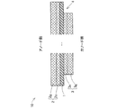
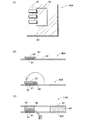
図13(A),(B)は、第2のセパレータ40に設けられた酸素流路溝41の機能を説明するための模式図である。図13(A)には、本実施例における他の構成例として、酸素流路溝41が省略された第2のセパレータ40と、カソード3とにガス拡散部材20が狭持された状態を図示してある。一方、図13(B)には、本実施例と同様な構成例として、酸素流路溝41が設けられた第2のセパレータ40と、カソード3とにガス拡散部材20が狭持された状態を図示してある。   FIGS. 13A and 13B are schematic views for explaining the function of the oxygen channel groove 41 provided in the second separator 40. FIG. 13A shows a state in which the gas diffusion member 20 is sandwiched between the second separator 40 in which the oxygen channel groove 41 is omitted and the cathode 3 as another configuration example in the present embodiment. It is shown. On the other hand, in FIG. 13B, as a configuration example similar to the present embodiment, the gas diffusion member 20 is sandwiched between the second separator 40 provided with the oxygen channel groove 41 and the cathode 3. Is shown.

第2のセパレータ40において酸素流路溝41が省略された場合には、酸素は、ガス拡散部材20に対して、その入口側面側からのみ流入することになる(図13(A))。しかし、ガス拡散部材20は、連結壁部21eの壁面が、その酸素の流入方向に面するように配置されている。そのため、この構成例では、酸素がガス拡散部材20に流入する際の圧力損失が比較的高くなる。これは、ガス拡散部材20の出口側についても同様である。   When the oxygen channel groove 41 is omitted in the second separator 40, oxygen flows into the gas diffusion member 20 only from the inlet side surface (FIG. 13A). However, the gas diffusion member 20 is disposed such that the wall surface of the connecting wall portion 21e faces the oxygen inflow direction. Therefore, in this configuration example, the pressure loss when oxygen flows into the gas diffusion member 20 is relatively high. The same applies to the outlet side of the gas diffusion member 20.

これに対して、第2のセパレータ40に酸素流路溝41が設けられている場合には、酸素は、ガス拡散部材20に対して、酸素流路溝41を介して、その背面側からも流入可能となる(図13(B))。ここで、ガス拡散部材20の貫通孔25を囲む壁面は、第2のセパレータ40の外表面に対して傾斜角を有して配置されており、ガス拡散部材20は、第2のセパレータ40の外表面側に向かって開口するように配置されているものと解釈することができる。   On the other hand, in the case where the second separator 40 is provided with the oxygen channel groove 41, the oxygen also flows from the back side of the gas diffusion member 20 via the oxygen channel groove 41. Inflow becomes possible (FIG. 13B). Here, the wall surface surrounding the through hole 25 of the gas diffusion member 20 is disposed with an inclination angle with respect to the outer surface of the second separator 40, and the gas diffusion member 20 includes the second separator 40. It can be interpreted that it is arranged so as to open toward the outer surface side.

即ち、第2のセパレータ40に酸素流路溝41が設けられていれば、ガス拡散部材20に対して、酸素を、その入口側面側からの導入に加えて、その開口方向に沿った方向から導入することが可能となる。従って、この構成例の場合には、酸素がガス拡散部材20に流入する際の圧力損失を低くすることができる。これは、ガス拡散部材20の出口側についても同様である。   That is, if the oxygen flow path groove 41 is provided in the second separator 40, oxygen is introduced into the gas diffusion member 20 from the direction along the opening direction in addition to the introduction from the inlet side surface side. It becomes possible to introduce. Therefore, in this configuration example, the pressure loss when oxygen flows into the gas diffusion member 20 can be reduced. The same applies to the outlet side of the gas diffusion member 20.

このように、本実施例の燃料電池100では、第2のセパレータ40に酸素流路溝41が設けられているため、燃料電池100内における酸素の圧力損失を低下させることができる。従って、燃料電池100におけるカソード3への酸素の供給効率を向上させることができるとともに、カソード3側における排水性を向上させることができる。   Thus, in the fuel cell 100 of the present embodiment, the oxygen flow path groove 41 is provided in the second separator 40, so that the pressure loss of oxygen in the fuel cell 100 can be reduced. Accordingly, it is possible to improve the efficiency of supplying oxygen to the cathode 3 in the fuel cell 100 and improve drainage on the cathode 3 side.

また、本実施例の燃料電池100では、第2のセパレータ40の酸素流路溝41は、燃料電池100を構成したときに、第1のセパレータ30の水素流路溝35と互いに勘合し合うように形成されている。即ち、本実施例の燃料電池100では、その積層方向に垂直な方向に沿ってみたときに、水素/冷媒の流路溝と、酸素の流路溝とが互いに重なり合う。さらに、燃料電池100では、それら流体の流路溝と、シール部材70の配置される空間とが互いに重なり合う。このように、本実施例の燃料電池100では、単セル110同士の間に形成される空間が、流体流路やシール部材の配置領域として効率的に利用されており、そのサイズが積層方向に大型化してしまうことが抑制されている。   Further, in the fuel cell 100 of the present embodiment, the oxygen channel groove 41 of the second separator 40 fits with the hydrogen channel groove 35 of the first separator 30 when the fuel cell 100 is configured. Is formed. That is, in the fuel cell 100 of the present embodiment, the hydrogen / refrigerant flow channel and the oxygen flow channel overlap each other when viewed along the direction perpendicular to the stacking direction. Further, in the fuel cell 100, the flow path grooves of these fluids and the space in which the seal member 70 is disposed overlap each other. As described above, in the fuel cell 100 according to the present embodiment, the space formed between the single cells 110 is efficiently used as the arrangement region of the fluid flow path and the seal member, and the size thereof is in the stacking direction. An increase in size is suppressed.

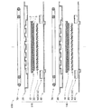
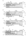
図14(A)〜(F)は、本実施例の単セル110の組み立て工程を説明するための模式図である。本実施例の単セル110は、膜電極接合体10を第1と第2のセパレータ30,40で狭持して、接着層60によって一体化した後に、打ち抜き工程によって、各マニホールドM1〜M8を形成する。具体的には、単セル110は、以下のように組み立てられる。   FIGS. 14A to 14F are schematic views for explaining an assembly process of the unit cell 110 of this embodiment. In the unit cell 110 of the present embodiment, the membrane electrode assembly 10 is sandwiched between the first and second separators 30 and 40 and integrated by the adhesive layer 60, and then the manifolds M1 to M8 are formed by a punching process. Form. Specifically, the single cell 110 is assembled as follows.

なお、図14(A)〜(F)には、水素と酸素の供給用マニホールドM1,M3側の端部領域を図示してあり、以下では、その領域における工程について説明する。しかし、図示されていない水素と酸素の排出用マニホールドM2,M4側の端部領域についても、工程の内容は同様である。また、図14(A)〜(D)では、後続する打ち抜き工程によってマニホールドM1,M3が形成される領域を破線で図示してある。   14A to 14F show end regions on the side of the supply manifolds M1 and M3 for supplying hydrogen and oxygen, and the steps in those regions will be described below. However, the contents of the process are the same for the end regions on the hydrogen and oxygen discharge manifolds M2 and M4 (not shown). 14A to 14D, the regions where the manifolds M1 and M3 are formed by the subsequent punching process are indicated by broken lines.

第1工程では、第2のセパレータ40の外表面上にガス拡散部材20と膜電極接合体10とを積層配置し、カソード3の側端面と、ガス拡散部材20の側端部に、速乾性の液状接着剤を塗布して、第1の接着部61を形成する(図14(A))。即ち、この工程では、第2のセパレータ40と、膜電極接合体10と、ガス拡散部材20とが一体化される。そして、水素通路部材51を所定の位置に配置するとともに、酸素通路部材52を所定の位置に配置する(図14(B))。   In the first step, the gas diffusion member 20 and the membrane electrode assembly 10 are laminated on the outer surface of the second separator 40, and the quick-drying property is provided on the side end surface of the cathode 3 and the side end portion of the gas diffusion member 20. The first adhesive portion 61 is formed by applying the liquid adhesive (FIG. 14A). That is, in this step, the second separator 40, the membrane electrode assembly 10, and the gas diffusion member 20 are integrated. Then, the hydrogen passage member 51 is disposed at a predetermined position, and the oxygen passage member 52 is disposed at a predetermined position (FIG. 14B).

なお、この際に、水素通路部材51および酸素通路部材52は、それぞれの端部が、マニホールドM1〜M4の形成領域内に配置されることが好ましい。このように配置することによって、マニホールドMの打ち抜き工程の際に、第1と第2のセパレータ30,40の端部が変形してしまうことを、より確実に抑制することができる。   At this time, it is preferable that the end portions of the hydrogen passage member 51 and the oxygen passage member 52 are arranged in the formation regions of the manifolds M1 to M4. By arranging in this way, it is possible to more reliably prevent the end portions of the first and second separators 30 and 40 from being deformed during the punching process of the manifold M.

第2工程では、第2と第3の接着部62,63の形成領域に速乾性の液状接着剤を塗布しつつ、第1のセパレータ30を膜電極接合体10の上に積層配置する(図14(C),(D))。なお、このとき、第3の接着部63を形成するための接着剤は、マニホールドMの形成領域まで、はみ出して塗布されることが好ましい。これによって、マニホールドMの外周領域には、第1と第2のセパレータ30,40の間に確実に接着層60が配置されることになるため、短絡を抑制できる。第3工程では、接着剤が乾燥した後に、各マニホールドM1〜M8を打ち抜き工程により形成する(図14(E),(F))。   In the second step, the first separator 30 is stacked on the membrane electrode assembly 10 while applying a quick-drying liquid adhesive to the formation region of the second and third adhesive portions 62 and 63 (see FIG. 14 (C), (D)). At this time, it is preferable that the adhesive for forming the third adhesive portion 63 protrudes to the formation area of the manifold M and is applied. Accordingly, since the adhesive layer 60 is surely disposed between the first and second separators 30 and 40 in the outer peripheral region of the manifold M, a short circuit can be suppressed. In the third step, after the adhesive is dried, the manifolds M1 to M8 are formed by a punching step (FIGS. 14E and 14F).

なお、本実施例の単セル110の組み立て工程は、上記の工程に限定されるものではない。例えば、マニホールドM1〜M6は、上記のような打ち抜き工程によって形成されなくとも良い。具体的には、マニホールドM1〜M6を構成する貫通孔が予め形成された第1と第2のセパレータ30,40を準備しておき、それら第1と第2のセパレータ30,40によって膜電極接合体10を狭持した後に、接着層60を形成するものとしても良い。   In addition, the assembly process of the single cell 110 of a present Example is not limited to said process. For example, the manifolds M1 to M6 may not be formed by the punching process as described above. Specifically, first and second separators 30 and 40 in which through holes constituting the manifolds M1 to M6 are formed in advance are prepared, and membrane electrode bonding is performed by the first and second separators 30 and 40. The adhesive layer 60 may be formed after the body 10 is held.

ここで、本実施例の燃料電池100では、上述したように、各マニホールドM1〜M8の打ち抜き工程において第1と第2のセパレータ30,40の端部が変形してしまうことが、当該端部に配置されたガス通路部材50によって抑制される。また、本実施例の燃料電池100であれば、以下に説明する参考例の燃料電池100aの製造工程において、各マニホールドM1〜M8を上述したのと同様な打ち抜き工程によって形成する場合に発生する可能性のある不具合が抑制される。   Here, in the fuel cell 100 of the present embodiment, as described above, the end portions of the first and second separators 30 and 40 are deformed in the punching process of the manifolds M1 to M8. It is suppressed by the gas passage member 50 arranged in the. Further, in the case of the fuel cell 100 of the present embodiment, it may occur when the manifolds M1 to M8 are formed by the same punching process as described above in the manufacturing process of the fuel cell 100a of the reference example described below. The characteristic trouble is suppressed.

図15(A),(B)は、参考例としての燃料電池100aの構成を説明するための概略図である。図15(A)は、水素供給用マニホールドM1とアノード2との間における水素通路の構成を示す、図11(A)と同様な概略断面図である。図15(B)は、酸素供給用マニホールドM3とカソード3との間における酸素通路の構成を示す、図12(A)と同様な概略断面図である。   FIGS. 15A and 15B are schematic diagrams for explaining the configuration of a fuel cell 100a as a reference example. FIG. 15A is a schematic cross-sectional view similar to FIG. 11A, showing the configuration of the hydrogen passage between the hydrogen supply manifold M1 and the anode 2. FIG. FIG. 15B is a schematic cross-sectional view similar to FIG. 12A, showing the configuration of the oxygen passage between the oxygen supply manifold M3 and the cathode 3. FIG.

参考例の燃料電池100aは、複数の単セル110aが積層された積層構造を有する。各単セル110aの構成は、マニホールドMと膜電極接合体10との間に形成されるガス通路の構成が異なる点以外は、本実施例の単セル110の構成とほぼ同様である。なお、参考例の燃料電池100aでは、排出側のガス通路の構成は、以下に説明する供給側のガス通路の構成と同様であるため、その図示および説明は省略する。   The fuel cell 100a of the reference example has a stacked structure in which a plurality of single cells 110a are stacked. The configuration of each single cell 110a is substantially the same as the configuration of the single cell 110 of the present embodiment, except that the configuration of the gas passage formed between the manifold M and the membrane electrode assembly 10 is different. In the fuel cell 100a of the reference example, the configuration of the gas passage on the discharge side is the same as the configuration of the gas passage on the supply side described below, and illustration and description thereof are omitted.

参考例の燃料電池100aでは、水素供給用マニホールドM1とアノード2との間の水素通路は、板状部材である第1のシーリングプレート55(「水素シーリングプレート55」とも呼ぶ)によって形成される(図15(A))。水素シーリングプレート55は、膜電極接合体10のアノード2側とカソード3側とを分離するとともに、水素通路の底面を構成する。   In the fuel cell 100a of the reference example, the hydrogen passage between the hydrogen supply manifold M1 and the anode 2 is formed by a first sealing plate 55 (also referred to as a “hydrogen sealing plate 55”) that is a plate-like member ( FIG. 15 (A)). The hydrogen sealing plate 55 separates the anode 2 side and the cathode 3 side of the membrane electrode assembly 10 and constitutes the bottom surface of the hydrogen passage.

水素シーリングプレート55は、一方の端部の外表面が、電解質膜1の端部におけるカソード3側の外表面と面接触し、他方の端部の端面が水素供給用マニホールドM1の壁面を構成するように、第2のセパレータ40の表面と並行に配置される。また、水素シーリングプレート55は、カソード3の端部から突出した電解質膜1の外表面の一部が第1の接着部61aと直接的に接触するように、カソード3から離間して配置される。   The outer surface of one end of the hydrogen sealing plate 55 is in surface contact with the outer surface on the cathode 3 side at the end of the electrolyte membrane 1, and the end surface of the other end constitutes the wall surface of the hydrogen supply manifold M1. Thus, it arrange | positions in parallel with the surface of the 2nd separator 40. FIG. The hydrogen sealing plate 55 is disposed away from the cathode 3 so that a part of the outer surface of the electrolyte membrane 1 protruding from the end of the cathode 3 is in direct contact with the first adhesive portion 61a. .

なお、第1のセパレータ30のシール部材配置部31には、水素の流路空間が確保されるように、水素シーリングプレート55を保持する保持部37が、水素シーリングプレート55側に突出した複数の凸部として形成されている。保持部37は、シール部材70が配置位置からずれた位置において第1のセパレータ30をプレス加工することにより形成される。   In addition, in the seal member arrangement portion 31 of the first separator 30, a holding portion 37 that holds the hydrogen sealing plate 55 has a plurality of protrusions protruding toward the hydrogen sealing plate 55 so as to secure a hydrogen flow passage space. It is formed as a convex part. The holding portion 37 is formed by pressing the first separator 30 at a position where the seal member 70 is displaced from the arrangement position.

水素シーリングプレート55と第2のセパレータ40との間には、第1の接着部61aが形成される。第1の接着部61aは、ガス拡散部材20の端部とカソード3の端面とをシールするシール部として機能する。また、第1の接着部61aの側面は、水素供給用マニホールドM1の壁面の一部を構成する。   A first bonding portion 61 a is formed between the hydrogen sealing plate 55 and the second separator 40. The first bonding portion 61 a functions as a seal portion that seals the end portion of the gas diffusion member 20 and the end surface of the cathode 3. The side surface of the first bonding portion 61a constitutes a part of the wall surface of the hydrogen supply manifold M1.

水素供給用マニホールドM1から供給された水素は、水素シーリングプレート55と第1のセパレータ30との間の空隙として形成された水素通路に分岐流入する。そして、保持部37をすり抜けて、第1のセパレータ30に設けられた水素流路溝35を介して、アノード2へと供給される。なお、アノード2側の排ガスは、水素シーリングプレート55によって、供給側と同様に形成された水素通路を介して、水素排出用マニホールドM2へと排出される(図示は省略)。   The hydrogen supplied from the hydrogen supply manifold M1 branches and flows into a hydrogen passage formed as a gap between the hydrogen sealing plate 55 and the first separator 30. Then, it passes through the holding portion 37 and is supplied to the anode 2 through the hydrogen flow channel 35 provided in the first separator 30. The exhaust gas on the anode 2 side is discharged by the hydrogen sealing plate 55 to the hydrogen discharge manifold M2 through a hydrogen passage formed in the same manner as on the supply side (not shown).

参考例の燃料電池100aでは、酸素供給用マニホールドM3とカソード3との間の酸素通路は、板状部材である第2のシーリングプレート56(「酸素シーリングプレート56」とも呼ぶ)と、ガス拡散部材20とによって形成される(図15(B))。なお、この参考例の燃料電池100aでは、第2のセパレータ40に酸素流路溝41は設けられていない。   In the fuel cell 100a of the reference example, the oxygen passage between the oxygen supply manifold M3 and the cathode 3 has a second sealing plate 56 (also referred to as “oxygen sealing plate 56”) that is a plate-like member, and a gas diffusion member. 20 (FIG. 15B). In the fuel cell 100a of this reference example, the oxygen separator groove 41 is not provided in the second separator 40.

参考例の燃料電池100aでは、ガス拡散部材20の配置領域は、カソード3の外周端を超えて、第1と第2のセパレータ30,40の酸素供給用マニホールドM3まで延長されている。即ち、ガス拡散部材20の入口側面側の端部が、酸素供給用マニホールドM3と直接的に接続されている。   In the fuel cell 100a of the reference example, the arrangement region of the gas diffusion member 20 extends beyond the outer peripheral end of the cathode 3 to the oxygen supply manifold M3 of the first and second separators 30 and 40. That is, the end of the gas diffusion member 20 on the inlet side surface side is directly connected to the oxygen supply manifold M3.

酸素シーリングプレート56は、その端面がカソード3の端面と面接触するように配置される。また、酸素シーリングプレート56は、ガス拡散部材20のカソード3の外周端部より突出した正面側を被覆するように配置される。ただし、酸素シーリングプレート56の酸素供給用マニホールドM3側の一辺は、第1と第2のセパレータ30,40の酸素供給用マニホールドM3より内側(膜電極接合体10側)に位置している。これによって、ガス拡散部材20の酸素供給用マニホールドM3側の端部は、その正面側が酸素供給用マニホールドM3に向かって露出する。   The oxygen sealing plate 56 is disposed such that its end surface is in surface contact with the end surface of the cathode 3. The oxygen sealing plate 56 is disposed so as to cover the front side of the gas diffusion member 20 protruding from the outer peripheral end of the cathode 3. However, one side of the oxygen sealing plate 56 on the oxygen supply manifold M3 side is located inside (on the membrane electrode assembly 10 side) of the oxygen supply manifold M3 of the first and second separators 30 and 40. As a result, the front side of the end portion of the gas diffusion member 20 on the oxygen supply manifold M3 side is exposed toward the oxygen supply manifold M3.

酸素シーリングプレート56と第1のセパレータ30との間には、第2の接着部62aが形成される。第2の接着部62aは、酸素供給用マニホールドM3の酸素がアノード2へと流入しないように、膜電極接合体10の端面をシールするように形成される。   A second bonding portion 62 a is formed between the oxygen sealing plate 56 and the first separator 30. The second adhesive portion 62a is formed to seal the end surface of the membrane electrode assembly 10 so that oxygen in the oxygen supply manifold M3 does not flow into the anode 2.

酸素供給用マニホールドM3に供給された酸素は、酸素供給用マニホールドM3内に露出しているガス拡散部材20の端部に、その入口側面側および正面側から流入し、カソード3へと供給される。ところで、この参考例の燃料電池100aでは、酸素は、酸素供給用マニホールドM3に、膜電極接合体10のカソード3側(図15(B)の紙面下側)から供給されることが好ましい。これによって、ガス拡散部材20への酸素の流入量を増大させることができる。カソード3側の排ガスは、ガス拡散部材20の端部から直接的に、酸素排出用マニホールドM4へと排出される(図示は省略)。   The oxygen supplied to the oxygen supply manifold M3 flows into the end portion of the gas diffusion member 20 exposed in the oxygen supply manifold M3 from the inlet side surface and the front side, and is supplied to the cathode 3. . By the way, in the fuel cell 100a of this reference example, it is preferable that oxygen is supplied to the oxygen supply manifold M3 from the cathode 3 side of the membrane electrode assembly 10 (the lower side of the drawing in FIG. 15B). Thus, the amount of oxygen flowing into the gas diffusion member 20 can be increased. The exhaust gas on the cathode 3 side is discharged directly from the end of the gas diffusion member 20 to the oxygen discharge manifold M4 (not shown).

図16(A)〜(F)は、参考例の単セル110aの組み立て工程を説明するための模式図である。参考例の単セル110aは、本実施例の単セル110と同様に、膜電極接合体10と第1と第2のセパレータ30,40とを接着層60によって一体化した後の打ち抜き工程によって、各マニホールドM1〜M6が形成される。具体的には、単セル110aは、以下のように組み立てられる。   FIGS. 16A to 16F are schematic views for explaining an assembly process of the unit cell 110a of the reference example. The single cell 110a of the reference example is similar to the single cell 110 of the present example by a punching process after the membrane electrode assembly 10 and the first and second separators 30 and 40 are integrated by the adhesive layer 60. Each manifold M1-M6 is formed. Specifically, the single cell 110a is assembled as follows.

なお、図16(A)〜(F)には、水素と酸素の供給用マニホールドM1,M3側の端部領域を図示してあり、以下では、その領域における工程について説明する。しかし、図示されていない水素と酸素の排出用マニホールドM2,M4側の端部領域についても、工程の内容は同様である。また、図16(A)〜(D)では、後続する打ち抜き工程によってマニホールドM1,M3が形成される領域を破線で図示してある。   FIGS. 16A to 16F show end regions on the hydrogen and oxygen supply manifolds M1 and M3 side, and the processes in these regions will be described below. However, the contents of the process are the same for the end regions on the hydrogen and oxygen discharge manifolds M2 and M4 (not shown). Further, in FIGS. 16A to 16D, regions where the manifolds M1 and M3 are formed by the subsequent punching process are illustrated by broken lines.

第1工程では、第2のセパレータ40の外表面上にガス拡散部材20と膜電極接合体10とを積層配置するとともに、膜電極接合体10の上に第1のセパレータ30を積層配置する(図16(A),(B))。このときに、各シーリングプレート55,56も所定の位置に配置しておく。第1または第2のセパレータ30,40と各シーリングプレート55,56の間には、各シーリングプレート55,56を保持するための部材が配置されるものとしても良い。   In the first step, the gas diffusion member 20 and the membrane electrode assembly 10 are stacked on the outer surface of the second separator 40, and the first separator 30 is stacked on the membrane electrode assembly 10 ( FIG. 16 (A), (B)). At this time, the sealing plates 55 and 56 are also arranged at predetermined positions. A member for holding each sealing plate 55, 56 may be disposed between the first or second separator 30, 40 and each sealing plate 55, 56.

なお、水素供給用マニホールドM1側の端部では、水素シーリングプレート55は、その一辺が水素供給用マニホールドM1の形成領域内に配置されることが好ましい。また、酸素供給用マニホールドM3側の端部では、ガス拡散部材20の端部が、酸素供給用マニホールドM3の形成領域内にまで突出して配置されていることが好ましい。   Note that, at the end portion on the hydrogen supply manifold M1 side, it is preferable that one side of the hydrogen sealing plate 55 is disposed in the formation region of the hydrogen supply manifold M1. In addition, at the end portion on the oxygen supply manifold M3 side, the end portion of the gas diffusion member 20 is preferably disposed so as to protrude into the formation region of the oxygen supply manifold M3.

第2工程では、速乾性の液状接着剤によって接着層60を形成する。水素供給用マニホールドM1側の端部では、水素シーリングプレート55と、第2のセパレータ40との間(第1の接着部61aの形成領域)から接着剤を充填する(図16(C))。そして、そのまま連続して、水素供給用マニホールドM1の形成領域も含む第1と第2のセパレータ30,40の間の空間に接着剤を充填する。   In the second step, the adhesive layer 60 is formed with a quick-drying liquid adhesive. At the end of the hydrogen supply manifold M1 side, an adhesive is filled from between the hydrogen sealing plate 55 and the second separator 40 (formation region of the first bonding portion 61a) (FIG. 16C). Then, continuously, the adhesive is filled into the space between the first and second separators 30 and 40 including the region where the hydrogen supply manifold M1 is formed.

また、酸素供給用マニホールドM3側の端部では、酸素シーリングプレート56と第1のセパレータ30との間(第2の接着部62aの形成領域)に接着剤を充填する(図16(D))。そして、第1と第2のセパレータ30,40の間(第3の接着部63の形成領域)にも、接着剤を充填する。なお、このとき、接着剤は、酸素供給用マニホールドM3の形成領域にはみ出して塗布されることが好ましい。   Further, at the end on the oxygen supply manifold M3 side, an adhesive is filled between the oxygen sealing plate 56 and the first separator 30 (formation region of the second adhesive portion 62a) (FIG. 16D). . The adhesive is also filled between the first and second separators 30 and 40 (region where the third bonding portion 63 is formed). At this time, the adhesive is preferably applied so as to protrude into the formation region of the oxygen supply manifold M3.

第3工程では、接着剤が乾燥した後に、各マニホールドM1〜M8を打ち抜き工程により形成する(図16(E),(F))。こうした一連の工程によって、参考例の単セル110aを組み立てることができる。しかし、この参考例の単セル110aの組み立て工程では、接着層60を形成するための接着剤の塗布工程において、以下のような不具合が発生してしまう可能性がある。   In the third step, after the adhesive is dried, the manifolds M1 to M8 are formed by a punching step (FIGS. 16E and 16F). The single cell 110a of the reference example can be assembled through such a series of steps. However, in the assembly process of the unit cell 110a of this reference example, the following problems may occur in the adhesive application process for forming the adhesive layer 60.

図17(A)〜(D)は、参考例の単セル110aの組み立て工程において生じる不具合を説明するための模式図である。なお、図17(A)〜(D)にはそれぞれ、重力方向を示す矢印Gを図示してある。なお、以下の説明では、水素および酸素の供給用マニホールドM1,M3側の端部についてそれぞれ説明するが、排出用マニホールドM2,M4側の端部についても同様の不具合が生じる可能性がある。   FIGS. 17A to 17D are schematic diagrams for explaining problems that occur in the assembly process of the unit cell 110a of the reference example. In FIGS. 17A to 17D, an arrow G indicating the direction of gravity is illustrated. In the following description, the end portions on the hydrogen and oxygen supply manifolds M1 and M3 side will be described, respectively, but the same problem may occur on the end portions on the discharge manifolds M2 and M4 side.

図17(A)は、第2のセパレータ40側を重力方向下側として、水素供給用マニホールドM1側の端部に接着層60を形成する際に不具合が生じた状態を模式的に示している。また、図17(B),(C)はそれぞれ、第1のセパレータ30側を重力方向下側として、水素供給用マニホールドM1側の端部に接着層60を形成する際に不具合が生じるメカニズムを段階的に示している。   FIG. 17A schematically shows a state in which a problem has occurred when the adhesive layer 60 is formed at the end portion on the hydrogen supply manifold M1 side with the second separator 40 side being the lower side in the gravity direction. . FIGS. 17B and 17C each show a mechanism that causes a problem when the adhesive layer 60 is formed at the end portion on the hydrogen supply manifold M1 side with the first separator 30 side being the lower side in the gravity direction. Shown step by step.

図16(C)で説明したように、水素供給用マニホールドM1側の端部では、水素シーリングプレート55と第2のセパレータ40の間の空間と、第1と第2のセパレータ30,40の間の空間に連続して接着剤が塗布・充填される。このとき、第2のセパレータ40を重力方向下側とした場合には、第1と第2のセパレータ30,40の間に接着剤を充填する際に、水素シーリングプレート55と第1のセパレータ30との間の空間に接着剤が流入してしまう可能性がある(図17(A))。即ち、水素供給用マニホールドM1とアノード2との間の水素通路の入口が接着剤によって狭小化または閉塞されてしまう可能性がある。   As described with reference to FIG. 16C, at the end portion on the hydrogen supply manifold M1 side, the space between the hydrogen sealing plate 55 and the second separator 40 and the space between the first and second separators 30 and 40 are provided. The adhesive is continuously applied and filled in the space. At this time, when the second separator 40 is on the lower side in the gravitational direction, when the adhesive is filled between the first and second separators 30 and 40, the hydrogen sealing plate 55 and the first separator 30 are filled. There is a possibility that the adhesive will flow into the space between the two (FIG. 17A). That is, the entrance of the hydrogen passage between the hydrogen supply manifold M1 and the anode 2 may be narrowed or blocked by the adhesive.

また、第1のセパレータ30を重力方向下側として接着剤を充填する場合には、水素シーリングプレート55と第1のセパレータ30との間の段差において、接着剤が途切れてしまう可能性がある(図17(B))。接着剤が途切れてしまった後に、続けて接着剤を充填していくと、接着剤の一部が、水素シーリングプレート55と第1のセパレータ30との間の空間に流入するとともに、第2のセパレータ40側に空隙が生じてしまう可能性がある。即ち、この場合には、水素通路入口の狭小化または閉塞とともに、第2のセパレータ40と接着層60との間に生じた空隙を起点とした水素の漏洩経路が生じてしまう可能性がある。   In addition, when the adhesive is filled with the first separator 30 on the lower side in the gravity direction, the adhesive may be interrupted at the step between the hydrogen sealing plate 55 and the first separator 30 ( FIG. 17 (B)). When the adhesive is continuously filled after the adhesive is interrupted, a part of the adhesive flows into the space between the hydrogen sealing plate 55 and the first separator 30, and the second There is a possibility that voids are generated on the separator 40 side. That is, in this case, along with the narrowing or closing of the hydrogen passage entrance, there is a possibility that a hydrogen leakage path starting from the void formed between the second separator 40 and the adhesive layer 60 may occur.

図17(D)は、第2のセパレータ40側を重力方向下側として、酸素供給用マニホールドM3側の端部に接着層60を形成する際に不具合が生じた状態を模式的に示している。図16(D)で説明したように、酸素供給用マニホールドM3側の端部では、酸素シーリングプレート56と第1のセパレータ30の間の空間に接着剤が充填される。このとき、酸素シーリングプレート56の面上から、ガス拡散部材20へと接着剤が流動してしまう可能性がある。この場合には、ガス拡散部材20の正面側端部が接着剤によって閉塞されてしまうため、単セル110aを構成したときに、ガス拡散部材20の入口における酸素の圧力損失が増大してしまう。   FIG. 17D schematically shows a state in which a problem has occurred when the adhesive layer 60 is formed at the end portion on the oxygen supply manifold M3 side with the second separator 40 side being the lower side in the gravity direction. . As described in FIG. 16D, the space between the oxygen sealing plate 56 and the first separator 30 is filled with an adhesive at the end on the oxygen supply manifold M3 side. At this time, the adhesive may flow from the surface of the oxygen sealing plate 56 to the gas diffusion member 20. In this case, since the front side end of the gas diffusion member 20 is blocked by the adhesive, the pressure loss of oxygen at the inlet of the gas diffusion member 20 increases when the single cell 110a is configured.

しかし、本実施例の単セル110であれば、参考例の単セル110aの場合ほど接着剤を連続的に長い距離で塗布・充填したりする部位がない(図14)。また、ガス流路の入口を構成する段差を介して連続して接着剤を塗布する部位もない。そのため、本実施例の単セル110であれば、接着層60を形成するための接着剤の塗布量を低減するとともに、その塗布工程をより簡易化することができ、図17で説明したような接着剤による不具合が生じることを抑制することができる。   However, in the case of the single cell 110 of this embodiment, there is no portion where the adhesive is continuously applied and filled at a long distance as in the case of the single cell 110a of the reference example (FIG. 14). Moreover, there is no part which applies an adhesive continuously through the level | step difference which comprises the inlet_port | entrance of a gas flow path. Therefore, with the single cell 110 of the present embodiment, the application amount of the adhesive for forming the adhesive layer 60 can be reduced, and the application process can be simplified, as described in FIG. Generation | occurrence | production of the malfunction by an adhesive agent can be suppressed.

このように、本実施例の燃料電池100であれば、単セル110やシール部材70が交換可能に構成されているため、そのメンテナンス性が向上している。また、凹凸加工によって流体流路が形成された単層のセパレータ30,40を用いることにより、単セル110が薄型化されている。さらに、燃料電池100では、その積層方向に垂直な方向に沿ってみたときに、ガス流路や冷媒流路、シール部材の配置空間が互いに重なり合うように構成されており、その全体のサイズが小型化されている。   As described above, in the fuel cell 100 according to the present embodiment, the unit cell 110 and the seal member 70 are configured to be replaceable, so that the maintainability thereof is improved. Moreover, the single cell 110 is made thin by using the single-layer separators 30 and 40 in which the fluid flow path is formed by the uneven processing. Further, the fuel cell 100 is configured such that the arrangement space of the gas flow path, the refrigerant flow path, and the seal member overlap each other when viewed along the direction perpendicular to the stacking direction, and the overall size is small. It has become.

そして、本実施例の燃料電池100では、各単セル110の反応ガスのマニホールドM1〜M4の端部に、補強部としても機能する壁部を有するガス通路部材50が配置されている。このガス通路部材50によって、第1と第2のセパレータ30,40の端部の変形が抑制され、反応ガスの流路入口や流路出口の閉塞や、短絡の発生が抑制される。また、本実施例の燃料電池100であれば、接着層60を形成するための接着剤の塗布量が低減され、接着剤の塗布工程を簡易化することができる。   In the fuel cell 100 of the present embodiment, the gas passage member 50 having a wall portion that also functions as a reinforcing portion is arranged at the end of the manifold M1 to M4 of the reaction gas of each single cell 110. By this gas passage member 50, deformation of the end portions of the first and second separators 30 and 40 is suppressed, and blocking of the reaction gas flow channel inlet and flow channel outlet and occurrence of a short circuit are suppressed. Further, in the fuel cell 100 of the present embodiment, the amount of adhesive applied to form the adhesive layer 60 is reduced, and the adhesive application process can be simplified.

B.第2実施例:
図18,図19は本発明の第2実施例としての燃料電池100Aに用いられる第2のセパレータ40Aの構成を説明するための概略図である。図18には、第2のセパレータ40Aにおける第1の面S1側を図示してある。また、図19(A),(B)にはそれぞれ、図18に示すA−A切断およびB−B切断における第2のセパレータ40Aの概略断面を図示してある。なお、図18には、ガス拡散部材20が配置される領域EMAを一点鎖線で図示してある。
B. Second embodiment:
18 and 19 are schematic views for explaining the configuration of the second separator 40A used in the fuel cell 100A as the second embodiment of the present invention. FIG. 18 illustrates the first surface S1 side of the second separator 40A. FIGS. 19A and 19B show schematic cross sections of the second separator 40A in the AA and BB cuts shown in FIG. 18, respectively. In FIG. 18, a region EMA where the gas diffusion member 20 is arranged is illustrated by a one-dot chain line.

ここで、第2実施例の燃料電池100Aは、以下に説明する点以外は、第1実施例で説明した燃料電池100と同様な構成である。燃料電池100Aでは、第2のセパレータ40に換えて、第2のセパレータ40Aが用いられ、反応ガスのマニホールドM1〜M4の端部には、ガス通路部材50に換えて、シーリングプレート55,56が配置される。そして、接着層60における接着剤の塗布領域が異なる。   Here, the fuel cell 100A of the second embodiment has the same configuration as the fuel cell 100 described in the first embodiment except for the points described below. In the fuel cell 100A, a second separator 40A is used instead of the second separator 40, and sealing plates 55 and 56 are provided at the end portions of the reaction gas manifolds M1 to M4 instead of the gas passage member 50. Be placed. And the application area | region of the adhesive agent in the contact bonding layer 60 differs.

第2のセパレータ40Aは、以下に説明する点以外は、第1実施例で説明した第2のセパレータ40(図7)と同様な構成であり、反応ガスや冷媒のためのマニホールドM1〜M6が貫通孔として形成されるとともに、酸素流路溝41が形成されている。また、第2のセパレータ40Aには、プレス加工により、第1の面S1側に突出させた部位が以下のように形成されている。   The second separator 40A has the same configuration as that of the second separator 40 (FIG. 7) described in the first embodiment except for the points described below, and manifolds M1 to M6 for reaction gas and refrigerant are provided. In addition to being formed as a through hole, an oxygen channel groove 41 is formed. Further, the second separator 40A is formed with a portion that protrudes toward the first surface S1 by pressing as follows.

第2のセパレータ40Aでは、水素の供給用および排出用マニホールドM1,M2のそれぞれと膜電極接合体10の配置領域との間に、水素通路を構成する並列な水素通路壁42が形成されている。また、酸素の供給用および排出用マニホールドM3,M4のそれぞれと膜電極接合体10の配置領域との間には、酸素通路を構成する並列な酸素通路壁43が形成されている。   In the second separator 40A, parallel hydrogen passage walls 42 that form hydrogen passages are formed between the supply and discharge manifolds M1 and M2 and the region where the membrane electrode assembly 10 is disposed. . Further, parallel oxygen passage walls 43 that form oxygen passages are formed between the oxygen supply and discharge manifolds M3 and M4 and the region where the membrane electrode assembly 10 is disposed.

さらに、第2のセパレータ40Aには、接着層60を形成するために接着剤を塗布する領域を突出させた接着剤塗布部44が形成されている。接着剤塗布部44は、第2のセパレータ40Aの第1の面S1において、以下の領域を囲むように形成されている。接着剤塗布部44は、水素の供給用および排出用のマニホールドM1,M2のそれぞれの形成領域を、水素通路壁42の形成領域を含めて囲むように形成されている。   Further, the second separator 40A is formed with an adhesive application portion 44 that protrudes a region where an adhesive is applied to form the adhesive layer 60. The adhesive application part 44 is formed so as to surround the following region on the first surface S1 of the second separator 40A. The adhesive application part 44 is formed so as to surround the formation regions of the hydrogen supply and discharge manifolds M <b> 1 and M <b> 2 including the formation region of the hydrogen passage wall 42.

また、接着剤塗布部44は、酸素用のマニホールドM3,M4の形成領域と、酸素通路壁43の形成領域と、ガス拡散部材20の配置領域EMAとを一つの領域として囲むように形成されている。さらに、接着剤塗布部44は、冷媒の供給用および排出用マニホールドM5,M6の形成領域をそれぞれ囲むように形成されている。   Further, the adhesive application part 44 is formed so as to surround the formation area of the oxygen manifolds M3 and M4, the formation area of the oxygen passage wall 43, and the arrangement area EMA of the gas diffusion member 20 as one area. Yes. Further, the adhesive application portion 44 is formed so as to surround the formation regions of the refrigerant supply and discharge manifolds M5 and M6, respectively.

なお、接着剤塗布部44の各通路壁42,43の形成領域と隣り合う端部には、各通路壁42,43の上に配置されるシーリングプレート55,56(後述)を係止して配置するために窪ませた段差部45が設けられている。また、第2のセパレータ40Aには、第1実施例の単セル110の接着層60に形成されていた空隙部65(図10)に相当する部位に、水素のための流路溝46が、接着剤塗布部44に挟まれた溝部として形成されている。   Note that sealing plates 55 and 56 (described later) disposed on the respective passage walls 42 and 43 are engaged with end portions adjacent to the formation regions of the respective passage walls 42 and 43 of the adhesive application portion 44. A step 45 that is recessed for placement is provided. Further, in the second separator 40A, a flow channel groove 46 for hydrogen is formed in a portion corresponding to the gap 65 (FIG. 10) formed in the adhesive layer 60 of the unit cell 110 of the first embodiment. It is formed as a groove part sandwiched between the adhesive application parts 44.

ここで、接着剤塗布部44は、第2のセパレータ40Aにおける第1の面S1側の面(以後、「接着剤塗布部44の上面」と呼ぶ)全体が、同一の仮想平面上に存在するように形成されている(図19)。また、各通路壁42,43の高さは、それらの上に配置されるシーリングプレート55,56の厚みの分だけ、接着剤塗布部44より低く形成されている。   Here, the adhesive application portion 44 has the entire surface on the first surface S1 side in the second separator 40A (hereinafter referred to as “the upper surface of the adhesive application portion 44”) on the same virtual plane. (FIG. 19). Moreover, the height of each channel | path wall 42 and 43 is formed lower than the adhesive application part 44 by the part of the thickness of the sealing plates 55 and 56 arrange | positioned on them.

また、第2実施例における第2のセパレータ40Aには、第1の面S1側に、通路壁42,43や接着剤塗布部44が凸部として設けられたことにより、第2の面S2側に形成された凹部に樹脂部材47が充填されている。これによって、第2のセパレータ40Aの第2の面S2側は、酸素流路溝41のために突出している部位以外は、平坦な面となるように構成されている。   Further, the second separator 40A in the second embodiment is provided with the passage walls 42 and 43 and the adhesive application portion 44 as convex portions on the first surface S1 side, so that the second surface S2 side is provided. The resin member 47 is filled in the concave portion formed in. Thus, the second surface S2 side of the second separator 40A is configured to be a flat surface except for a portion protruding for the oxygen flow channel 41.

なお、燃料電池100Aでは、各単セル110Aの間に配置されるシール部材70は、この樹脂部材47によって平坦化された面と、第1のセパレータ30のシール部材配置部31の底面とに狭持される。従って、第2のセパレータ40Aの基材に上述した凹凸部が形成されることによって、燃料電池100Aにおけるシール性が低下してしまうことが抑制されている。   In the fuel cell 100A, the seal member 70 disposed between the single cells 110A is narrowed between the surface flattened by the resin member 47 and the bottom surface of the seal member placement portion 31 of the first separator 30. Be held. Therefore, it is suppressed that the sealing property in fuel cell 100A falls by forming the uneven part mentioned above in the base material of the 2nd separator 40A.

図20,図21は、第2実施例の燃料電池100Aの構成を説明するための概略図である。図20(A)は、図18に示すX−X断面に相当する部位における燃料電池100Aの概略断面図である。また、図20(B)は、図20(A)に示すB−B切断における燃料電池100Aの概略断面図である。   20 and 21 are schematic diagrams for explaining the configuration of the fuel cell 100A of the second embodiment. FIG. 20A is a schematic cross-sectional view of the fuel cell 100A at a portion corresponding to the XX cross section shown in FIG. FIG. 20B is a schematic cross-sectional view of the fuel cell 100A taken along the line BB shown in FIG.

図21(A)は、図18に示すY−Y断面に相当する部位における燃料電池100Aの概略断面図である。また、図21(B)は、図21(A)に示すB−B切断における燃料電池100Aの概略断面図である。   FIG. 21A is a schematic cross-sectional view of the fuel cell 100A at a portion corresponding to the YY cross section shown in FIG. FIG. 21B is a schematic cross-sectional view of the fuel cell 100A taken along the line BB shown in FIG.

燃料電池100Aでは、第2のセパレータ40Aに設けられた水素通路壁42および酸素通路壁43の上にそれぞれ、板状部材である水素シーリングプレート55および酸素シーリングプレート56が架設配置される。各シーリングプレート55,56は、その端部が、接着剤塗布部44に設けられた段差部45に係止されることにより、その外表面が接着剤塗布部44の上面と連続した一平面を形成する。   In the fuel cell 100A, a hydrogen sealing plate 55 and an oxygen sealing plate 56, which are plate-like members, are installed over the hydrogen passage wall 42 and the oxygen passage wall 43 provided in the second separator 40A, respectively. Each of the sealing plates 55 and 56 is engaged with a stepped portion 45 provided in the adhesive application portion 44 so that the outer surface of the sealing plates 55 and 56 is continuous with the upper surface of the adhesive application portion 44. Form.

そして、燃料電池100Aでは、各シーリングプレート55の外表面と、接着剤塗布部44の上面とにそれぞれ接着剤が塗布されて接着層60が形成される。これによって、第1と第2のセパレータ30,40Aと、膜電極接合体10とが一体化される。なお、接着塗剤布部44に設けられ段差部45によって、接着剤の塗布工程の際に、接着剤塗布部44の上面とシーリングプレート55,56との境界から、ガス通路内に接着剤が流入してしまうことが抑制されている。   In the fuel cell 100A, the adhesive layer 60 is formed by applying an adhesive to the outer surface of each sealing plate 55 and the upper surface of the adhesive application portion 44. Thus, the first and second separators 30 and 40A and the membrane electrode assembly 10 are integrated. Note that the step 45 provided in the adhesive coating cloth part 44 causes the adhesive to enter the gas passage from the boundary between the upper surface of the adhesive application part 44 and the sealing plates 55 and 56 during the adhesive application process. Inflow is suppressed.

ここで、水素供給用マニホールドM1に供給された水素は、水素通路壁42と水素シーリングプレート55によって形成された水素通路に流入する。そして、第2のセパレータ40Aに設けられた流路溝46を介して、第1のセパレータ30の水素流路溝35へと流れて、アノード2に供給される(図20(A))。アノード2側の排ガスは、第1のセパレータ30の水素流路溝35から第2のセパレータ40Aの流路溝46を経て、水素通路壁42と水素シーリングプレート55によって形成された水素通路へと流れて、水素排出用マニホールドM2から排出される(図示せず)。   Here, the hydrogen supplied to the hydrogen supply manifold M <b> 1 flows into the hydrogen passage formed by the hydrogen passage wall 42 and the hydrogen sealing plate 55. Then, it flows into the hydrogen flow channel 35 of the first separator 30 via the flow channel 46 provided in the second separator 40A, and is supplied to the anode 2 (FIG. 20A). The exhaust gas on the anode 2 side flows from the hydrogen channel groove 35 of the first separator 30 to the hydrogen channel formed by the hydrogen channel wall 42 and the hydrogen sealing plate 55 through the channel groove 46 of the second separator 40A. Then, it is discharged from the hydrogen discharge manifold M2 (not shown).

一方、酸素供給用マニホールドM3に供給された酸素は、酸素通路壁43と酸素シーリングプレート56によって形成された酸素通路に流入する。そして、ガス拡散部材20へと流入し、カソード3に供給される(図21(A))。カソード3側の排ガスは、ガス拡散部材20から、酸素通路壁43と酸素シーリングプレート56によって形成された酸素通路を介して、酸素排出用マニホールドM4から排出される(図示せず)。   On the other hand, the oxygen supplied to the oxygen supply manifold M <b> 3 flows into an oxygen passage formed by the oxygen passage wall 43 and the oxygen sealing plate 56. Then, the gas flows into the gas diffusion member 20 and is supplied to the cathode 3 (FIG. 21A). The exhaust gas on the cathode 3 side is discharged from the oxygen diffusion manifold M4 from the gas diffusion member 20 through an oxygen passage formed by the oxygen passage wall 43 and the oxygen sealing plate 56 (not shown).

このように、第2実施例の燃料電池100Aであれば、第2のセパレータ40Aをプレス加工することにより、反応ガスのマニホールドM1〜M4の端部の補強部としても機能する通路壁42,43が形成されている。従って、第1と第2のセパレータ30,40Aにおける反応ガスのマニホールドM1〜M4の端部の変形が抑制される。   Thus, in the case of the fuel cell 100A of the second embodiment, the passage walls 42 and 43 that also function as reinforcing portions of the end portions of the reaction gas manifolds M1 to M4 by pressing the second separator 40A. Is formed. Therefore, deformation of the end portions of the reaction gas manifolds M1 to M4 in the first and second separators 30 and 40A is suppressed.

また、第2実施例の燃料電池100Aでは、第2のセパレータ40Aの接着剤塗布部44が突出している分だけ接着層60の厚みが、第1実施例の場合より低減されている。また、接着剤が塗布される接着剤塗布部44の上面と、シーリングプレート55,56の外表面とが、単一の仮想平面上にあり、接着剤の塗布が、より容易になっている。さらに、第2実施例の燃料電池100Aでは、第2のセパレータ40Aの第2の面S2側の凹部に樹脂部材47が充填されることにより、第2のセパレータ40Aの第1のシール面の平滑性が確保されている。   Further, in the fuel cell 100A of the second embodiment, the thickness of the adhesive layer 60 is reduced as compared with the case of the first embodiment by the amount by which the adhesive application portion 44 of the second separator 40A protrudes. Further, the upper surface of the adhesive application portion 44 to which the adhesive is applied and the outer surfaces of the sealing plates 55 and 56 are on a single virtual plane, so that the application of the adhesive is easier. Furthermore, in the fuel cell 100A of the second embodiment, the recess on the second surface S2 side of the second separator 40A is filled with the resin member 47, thereby smoothing the first seal surface of the second separator 40A. Is secured.

C.参考例:
図22は、参考例として、第1実施例で説明したガス通路部材50の他の形成方法を説明するための模式図である。この参考例では、以下に説明する工程により、単セル110の製造工程において、第1のセパレータ30を構成する基材の一部を用いて水素通路部材51が形成される。なお、以下の説明では、水素供給側の水素通路部材51の形成方法について説明するが、水素排出側の水素通路部材51についても同様に形成することが可能である。また、酸素通路部材52についても、同様な工程により形成することが可能である。
C. Reference example:
FIG. 22 is a schematic diagram for explaining another method of forming the gas passage member 50 described in the first embodiment as a reference example. In this reference example, the hydrogen passage member 51 is formed by using a part of the base material constituting the first separator 30 in the manufacturing process of the single cell 110 by the process described below. In the following description, a method for forming the hydrogen passage member 51 on the hydrogen supply side will be described. However, the hydrogen passage member 51 on the hydrogen discharge side can be formed in the same manner. The oxygen passage member 52 can also be formed by a similar process.

第1工程(図22(A))では、単セル110に組み付けられる前の第1のセパレータ30の基材に対して、水素供給用マニホールドM1の形成領域(破線で図示)の外周輪郭線を構成する4辺のうちの連続する3辺に沿って切れ込み(厚み方向に貫通する切断線)を入れる。なお、図22(A)では、当該切れ込みによって形成された切断線を実線で示してある。   In the first step (FIG. 22A), the outer peripheral contour line of the formation region (shown by a broken line) of the hydrogen supply manifold M1 is formed on the base material of the first separator 30 before being assembled to the single cell 110. Cut along notches (cutting lines that penetrate in the thickness direction) along three consecutive sides of the four sides to be configured. Note that in FIG. 22A, the cutting line formed by the cut is indicated by a solid line.

ここで、水素供給用マニホールドM1の外周輪郭線のうちで、切れ込みを入れられなかった一辺は、後の工程で水素通路部材51が配置される領域に隣接する一辺である。上記の切断線の形成により、第1のセパレータ30の基材には、水素用マニホールドM1の形成領域に折り曲げ可能な板片部90が形成される。この参考例に工程では、この板片部90によって、水素通路部材51を形成する。   Here, in the outer peripheral contour of the hydrogen supply manifold M1, one side that is not cut is one side adjacent to a region where the hydrogen passage member 51 is disposed in a later step. By forming the cutting line, a plate piece 90 that can be bent in the formation region of the hydrogen manifold M1 is formed on the base material of the first separator 30. In the process of this reference example, the hydrogen passage member 51 is formed by the plate piece 90.

第2工程(図22(B))では、板片部90に、プレス加工により波板状に凹凸する凹凸部位91を形成する。この凹凸部位91が、水素通路部材51における水素の流路溝を構成する。   In the second step (FIG. 22B), an uneven portion 91 that is uneven in a corrugated shape is formed on the plate piece 90 by pressing. The uneven portion 91 constitutes a hydrogen flow channel in the hydrogen passage member 51.

第3工程(図22(C))では、板片部90を、水素通路部材51の配置領域に向かって折り曲げる。このとき、板片部90と、第1のセパレータ30の外表面との間には、絶縁性部材92を介挿する。なお、絶縁性部材92に換えて、板片部90の外表面に絶縁皮膜を形成するものとしても良い。   In the third step (FIG. 22C), the plate piece 90 is bent toward the arrangement region of the hydrogen passage member 51. At this time, an insulating member 92 is interposed between the plate piece 90 and the outer surface of the first separator 30. Instead of the insulating member 92, an insulating film may be formed on the outer surface of the plate piece 90.

第4工程(図22(D))では、第1と第2のセパレータ30,40によって膜電極接合体10およびガス拡散部材20が狭持された状態(図示は省略)で接着層60を形成する。そして、各マニホールドMを形成するための打ち抜き工程によって、板片部90の折り曲げ部を切除する。これによって、水素用マニホールドM1が形成されるとともに、水素用マニホールドM1に連通する水素通路部材51が形成され、単セル110が完成する。   In the fourth step (FIG. 22D), the adhesive layer 60 is formed in a state where the membrane electrode assembly 10 and the gas diffusion member 20 are sandwiched by the first and second separators 30 and 40 (not shown). To do. Then, the bent portion of the plate piece 90 is cut out by a punching process for forming each manifold M. As a result, the hydrogen manifold M1 is formed, and the hydrogen passage member 51 communicating with the hydrogen manifold M1 is formed, whereby the single cell 110 is completed.

図23は、参考例として、第2実施例で説明した、反応ガスのマニホールドM1〜M4と、膜電極接合体10の発電領域とを連通するガス通路の他の形成方法を説明するための模式図である。この参考例では、以下に説明する工程により、単セル110Aの製造工程において、第2のセパレータ40Aを構成する基材の一部を用いて水素シーリングプレート55が形成される。なお、以下の説明では、水素供給側の水素通路の形成方法について説明するが、水素排出側の水素通路についても同様に形成することが可能である。また、酸素通路についても、同様な工程により形成することが可能である。   FIG. 23 is a schematic diagram for explaining another method of forming a gas passage communicating the reactant gas manifolds M1 to M4 and the power generation region of the membrane electrode assembly 10 described in the second embodiment as a reference example. FIG. In this reference example, the hydrogen sealing plate 55 is formed using a part of the base material constituting the second separator 40A in the manufacturing process of the single cell 110A by the process described below. In the following description, a method for forming the hydrogen passage on the hydrogen supply side will be described. However, the hydrogen passage on the hydrogen discharge side can be formed in the same manner. The oxygen passage can also be formed by a similar process.

第1工程(図23(A))では、プレス加工により通路壁42,43や接着剤塗布部44が形成された第2のセパレータ40Aの基材を準備する。そして、図22(A)で説明した第1工程と同様に、第2のセパレータ40Aの基材において、水素供給用マニホールドM1の形成領域の外周輪郭線に沿った切断線を形成して、板片部90を形成する。なお、図23では、接着剤塗布部44についての図示は省略してある。   In the first step (FIG. 23A), a base material for the second separator 40A in which the passage walls 42 and 43 and the adhesive application portion 44 are formed by pressing is prepared. Then, similarly to the first step described with reference to FIG. 22A, a cutting line is formed along the outer peripheral contour line of the formation region of the hydrogen supply manifold M1 in the base material of the second separator 40A. A piece 90 is formed. In FIG. 23, illustration of the adhesive application unit 44 is omitted.

第2工程(図23(B))では、板片部90を、水素通路壁42側へと折り返して、各水素通路壁42の上に架設・配置させる。即ち、この参考例では、この板片部90によって水素シーリングプレート55が形成される。   In the second step (FIG. 23B), the plate piece 90 is folded back toward the hydrogen passage wall 42 and is laid and placed on each hydrogen passage wall 42. That is, in this reference example, the hydrogen sealing plate 55 is formed by the plate piece 90.

第3工程(図23(C))では、板片部90の外表面および接着剤塗布部44(図示は省略)の上に接着剤を塗布して、第1と第2のセパレータ30,40Aによって膜電極接合体10およびガス拡散部材20(図示は省略)を狭持する。そして、各マニホールドMを形成するための打ち抜き工程によって、板片部90の折り曲げ部を切除する。これによって、水素用マニホールドM1が形成されるとともに、水素シーリングプレート55が配置された水素通路が形成され、単セル110Aが完成する。   In the third step (FIG. 23C), an adhesive is applied onto the outer surface of the plate piece 90 and the adhesive application portion 44 (not shown), and the first and second separators 30 and 40A are applied. Therefore, the membrane electrode assembly 10 and the gas diffusion member 20 (not shown) are sandwiched. Then, the bent portion of the plate piece 90 is cut out by a punching process for forming each manifold M. As a result, a hydrogen manifold M1 is formed and a hydrogen passage in which the hydrogen sealing plate 55 is disposed is formed, thereby completing the single cell 110A.

このように、図22,図23で説明した方法によれば、第1実施例および第2実施例で説明した単セル110,110Aを効率的に形成することが可能である。   Thus, according to the method described in FIGS. 22 and 23, the single cells 110 and 110A described in the first and second embodiments can be formed efficiently.

D.変形例:
なお、この発明は上記の実施例や実施形態に限られるものではなく、その要旨を逸脱しない範囲において種々の態様において実施することが可能であり、例えば次のような変形も可能である。
D. Variation:
The present invention is not limited to the above-described examples and embodiments, and can be implemented in various modes without departing from the gist thereof. For example, the following modifications are possible.

D1.変形例1:
上記実施例にでは、第1と第2のセパレータ30,40(40A)の間には、反応ガスのマニホールドM1〜M4の端部に、ガス通路部材50や通路壁42,43によって、複数の並列なガス通路が形成されていた。しかし、反応ガスのマニホールドM1〜M4の端部に形成されるガス通路は、他の構成を有する通路が形成されるものとしても良い。例えば、複数の略円柱状または略半球状の突起部が配列された、いわゆるディンプル形状のガス通路が形成されるものとしても良い。ガス通路は、反応ガスのマニホールドM1〜M4との接続部において、反応ガスのマニホールドM1〜M4の貫通方向に沿って突出する通路壁を有していれば良い。
D1. Modification 1:
In the above embodiment, a plurality of gas separators 50 and passage walls 42 and 43 are provided between the first and second separators 30 and 40 (40A) at the ends of the reaction gas manifolds M1 to M4. Parallel gas passages were formed. However, the gas passages formed at the end portions of the reaction gas manifolds M1 to M4 may be passages having other configurations. For example, a so-called dimple-shaped gas passage in which a plurality of substantially cylindrical or hemispherical protrusions are arranged may be formed. The gas passage only needs to have a passage wall that protrudes along the penetration direction of the reaction gas manifolds M1 to M4 at the connection portion between the reaction gas manifolds M1 to M4.

D2.変形例2:
上記実施例では、水素用および酸素用のそれぞれのマニホールドM1〜M4と膜電極接合体10との間に、マニホールドM1〜M4の貫通方向に沿って突出する壁部53や通路壁42,43が配置されていた。しかし、水素用または酸素用のガス通路のうち、いずれか一方において、それらの通路壁は省略されるものとしても良い。
D2. Modification 2:
In the above-described embodiment, the wall 53 and the passage walls 42 and 43 projecting along the penetrating direction of the manifolds M1 to M4 are provided between the manifolds M1 to M4 for hydrogen and oxygen and the membrane electrode assembly 10. Had been placed. However, in either one of the gas passages for hydrogen or oxygen, those passage walls may be omitted.

D3.変形例3:
上記実施例では、ガス拡散部材20としてエキスパンドメタルが用いられていた。しかし、ガス拡散部材20は省略されるものとしても良い。また、ガス拡散部材20としては、エキスパンドメタルに限らず、他の多孔質な導電性部材によって構成されるものとしても良い。ガス拡散部材20としては、例えば、発泡金属や、いわゆるパンチングメタルなどの多孔質に加工された金属板によって構成されるものとしても良い。なお、第2のセパレータ40には、第1のセパレータ20と同様な酸素のための流路溝が形成されるものとしても良い。
D3. Modification 3:
In the above embodiment, an expanded metal is used as the gas diffusion member 20. However, the gas diffusion member 20 may be omitted. Further, the gas diffusion member 20 is not limited to an expanded metal, and may be constituted by another porous conductive member. As the gas diffusion member 20, for example, a metal plate processed into a porous material such as foam metal or so-called punching metal may be used. The second separator 40 may be formed with a flow channel for oxygen similar to the first separator 20.

D4.変形例4:
上記実施例において、第2のセパレータ40,40Aには酸素流路溝41が形成されていた。しかし、酸素流路溝41は省略されるものとしても良い。ただし、図13で説明したように、酸素流路溝41が設けられていた方が、燃料電池100,100Aにおける酸素の圧力損失を低減できるため好ましい。
D4. Modification 4:
In the above embodiment, the oxygen separator grooves 41 are formed in the second separators 40 and 40A. However, the oxygen channel groove 41 may be omitted. However, as described with reference to FIG. 13, it is preferable that the oxygen flow channel 41 is provided because the pressure loss of oxygen in the fuel cells 100 and 100A can be reduced.

D5.変形例5:
上記実施例では、第1のセパレータ30の水素流路溝35は、複数の並列な直線流路溝として構成されていた。しかし、水素流路溝35は他の構成の流路溝として構成されるものとしても良い。例えば、水素流路溝35は、供給側の入口端部と排出側の出口端部とが、蛇腹状の往復流路溝によって連結された、いわゆるサーペンタイン状の流路溝として形成されるものとしても良い。また、水素流路溝35は、ディンプル状の流路を構成するように形成されても良い。第1のセパレータ30の水素流路溝35は、省略されるものとしても良い。この場合には、第1のセパレータ30とアノード2との間に、ガス拡散部材20が介挿・配置されるものとしても良い。
D5. Modification 5:
In the said Example, the hydrogen flow path groove 35 of the 1st separator 30 was comprised as several parallel linear flow path grooves. However, the hydrogen channel groove 35 may be configured as a channel groove having another configuration. For example, the hydrogen channel groove 35 is formed as a so-called serpentine-shaped channel groove in which a supply-side inlet end and a discharge-side outlet end are connected by a bellows-like reciprocating channel groove. Also good. Further, the hydrogen channel groove 35 may be formed so as to constitute a dimple-shaped channel. The hydrogen channel groove 35 of the first separator 30 may be omitted. In this case, the gas diffusion member 20 may be interposed and disposed between the first separator 30 and the anode 2.

D6.変形例6:
上記実施例では、第1の電極2がアノードとして機能し、第2の電極3がカソードとして機能していた。しかし、燃料電池100,100Aでは、第1の電極2をカソードとして機能させ、第2の電極3をアノードとして機能させるものとしても良い。
D6. Modification 6:
In the above embodiment, the first electrode 2 functions as an anode, and the second electrode 3 functions as a cathode. However, in the fuel cells 100 and 100A, the first electrode 2 may function as a cathode and the second electrode 3 may function as an anode.

D7.変形例7:
上記実施例において、膜電極接合体10は、アノード2よりカソード3の方が小さいサイズで形成されていた。しかし、膜電極接合体10では、カソード3の方がアノード2より小さいサイズで形成されるものとしても良いし、アノード2とカソード3とが、ほぼ同じサイズで構成されるものとしても良い。なお、アノード2とカソード3とを同じサイズで構成する場合には、電解質膜1の外周端部がアノード2またはカソード3の外周端部から突出されるように構成されることが好ましい。これによって、膜電極接合体10の端部におけるクロスリークの発生を抑制することができる。また、上記実施例では、各電極2,3がガス拡散層2g,3gを有していた。しかし、ガス拡散層2g,3gは省略されるものとしても良い。
D7. Modification 7:
In the above embodiment, the membrane electrode assembly 10 is formed in a size that the cathode 3 is smaller than the anode 2. However, in the membrane electrode assembly 10, the cathode 3 may be formed with a size smaller than the anode 2, or the anode 2 and the cathode 3 may be configured with substantially the same size. In the case where the anode 2 and the cathode 3 are configured with the same size, it is preferable that the outer peripheral end of the electrolyte membrane 1 is protruded from the outer peripheral end of the anode 2 or the cathode 3. As a result, the occurrence of cross leakage at the end of the membrane electrode assembly 10 can be suppressed. Moreover, in the said Example, each electrode 2 and 3 had the gas diffusion layers 2g and 3g. However, the gas diffusion layers 2g and 3g may be omitted.

D8.変形例8:
上記実施例では、燃料電池100,100Aを、その積層方向に垂直な方向(側面方向)に沿って見たときに、水素流路溝35と重なり合う空間にシール部材70が配置されていた。しかし、シール部材70を配置するための空間は、燃料電池100,100Aを、その側面方向に沿って見たときに、水素流路溝と重なり合う位置に形成されていなくとも良い。ただし、上記実施例のようにシール部材70を配置するための空間を形成することにより、燃料電池100,100Aの小型化が可能である。
D8. Modification 8:
In the above embodiment, when the fuel cells 100 and 100A are viewed along the direction perpendicular to the stacking direction (side surface direction), the seal member 70 is disposed in a space overlapping the hydrogen flow channel groove 35. However, the space for arranging the seal member 70 may not be formed at a position overlapping the hydrogen flow channel when the fuel cells 100 and 100A are viewed along the side surface direction. However, it is possible to reduce the size of the fuel cells 100 and 100A by forming a space for disposing the seal member 70 as in the above embodiment.

D9.変形例9:
上記実施例において、各単セル110,110Aの境界にはシール部材70が配置されていた。しかし、各単セル110,110Aの境界には、シール部材70に換えて、単セル110,110A同士を接着するとともに、当該境界位置のシール性を確保するための接着部が形成されるものとしても良い。ただし、この場合には、一部の単セル110,110Aの交換性が低下するため、燃料電池100,100Aのメンテナンス性が低下する可能性がある。
D9. Modification 9:
In the embodiment described above, the seal member 70 is disposed at the boundary between the single cells 110 and 110A. However, instead of the sealing member 70, the unit cells 110 and 110A are bonded to each other at the boundary between the unit cells 110 and 110A, and an adhesive portion for ensuring the sealing property at the boundary position is formed. Also good. However, in this case, the exchangeability of some of the single cells 110 and 110A is lowered, so that the maintainability of the fuel cells 100 and 100A may be lowered.

1…電解質膜
2…アノード(第1の電極)
3…カソード(第2の電極)
2c,3c…触媒層
2g,3g…ガス拡散層
4…段差部
10…膜電極接合体
20…ガス拡散部材
21a〜21d…壁部
21e…連結壁部
23…波板部
25…貫通孔
30…第1のセパレータ
31…シール部材配置部
32…外周端部
33…アノード配置部
35…水素流路溝
36…溝部
37…保持部
40,40A…第2のセパレータ
41…酸素流路溝
42…水素通路壁
43…酸素通路壁
44…接着剤塗布部
45…段差部
46…流路溝
47…樹脂部材
50…ガス通路部材
51…水素通路部材
51b…底面
51t…上面
52…酸素通路部材
53…壁部
55…水素シーリングプレート
56…酸素シーリングプレート
60…接着層
61,61a…第1の接着層
62,62a…第2の接着部
63…第3の接着部
65…空隙部
70…シール部材
90…板片部
91…凹凸部位
92…絶縁性部材
100,100A,100a…燃料電池
110,110A,110a…単セル
M…マニホールド
M1…水素供給用マニホールド
M2…水素排出用マニホールド
M3…酸素供給用マニホールド
M4…酸素排出用マニホールド
M5…冷媒供給用マニホールド
M6…冷媒排出用マニホールド
DESCRIPTION OF SYMBOLS 1 ... Electrolyte membrane 2 ... Anode (1st electrode)
3 ... Cathode (second electrode)
2c, 3c ... Catalyst layer 2g, 3g ... Gas diffusion layer 4 ... Stepped portion 10 ... Membrane electrode assembly 20 ... Gas diffusion member 21a-21d ... Wall portion 21e ... Connection wall portion 23 ... Corrugated plate portion 25 ... Through hole 30 ... 1st separator 31 ... Sealing member arrangement part 32 ... Outer peripheral edge part 33 ... Anode arrangement part 35 ... Hydrogen flow path groove 36 ... Groove part 37 ... Holding part 40, 40A ... Second separator 41 ... Oxygen flow path groove 42 ... Hydrogen Passage wall 43 ... Oxygen passage wall 44 ... Adhesive application part 45 ... Step part 46 ... Channel groove 47 ... Resin member 50 ... Gas passage member 51 ... Hydrogen passage member 51b ... Bottom surface 51t ... Upper surface 52 ... Oxygen passage member 53 ... Wall Part 55 ... Hydrogen sealing plate 56 ... Oxygen sealing plate 60 ... Adhesive layer 61, 61a ... First adhesive layer 62, 62a ... Second adhesive part 63 ... Third adhesive part 65 ... Cavity part 70 ... Si 90 ... Plate piece 91 ... Uneven portion 92 ... Insulating member 100, 100A, 100a ... Fuel cell 110, 110A, 110a ... Single cell M ... Manifold M1 ... Hydrogen supply manifold M2 ... Hydrogen discharge manifold M3 ... Manifold for supplying oxygen M4 ... Manifold for discharging oxygen M5 ... Manifold for supplying refrigerant M6 ... Manifold for discharging refrigerant

Claims (6)

複数の発電モジュールが積層された積層構造を有する燃料電池であって、
前記発電モジュールは、
電解質膜の両面に第1と第2の電極が配置された膜電極接合体と、
前記膜電極接合体の前記第1と第2の電極のそれぞれに対応して配置され、前記第1の電極に供給される第1の反応ガスのための第1のマニホールドを構成する貫通孔が形成された第1と第2のセパレータと、
前記膜電極接合体の外周において前記第1と第2のセパレータとを接着する接着層と、
を備え、
前記接着層には、厚み方向に貫通し、前記第1のマニホールドを構成する第1のマニホールド流路と、前記第1のマニホールド流路と、前記膜電極接合体の前記第1の電極との間を連通する第1の連通路と、が設けられ、
前記第1の連通路には、前記第1のマニホールド流路との接続部において、前記第1のマニホールドの貫通方向に延びるように立てられている第1の通路壁部が配置されている、燃料電池。
A fuel cell having a stacked structure in which a plurality of power generation modules are stacked,
The power generation module includes:
A membrane electrode assembly in which the first and second electrodes are disposed on both surfaces of the electrolyte membrane;
A through hole that is disposed corresponding to each of the first and second electrodes of the membrane electrode assembly and that constitutes a first manifold for a first reactive gas supplied to the first electrode. Formed first and second separators;
An adhesive layer for bonding the first and second separators on the outer periphery of the membrane electrode assembly;
With
The adhesive layer includes a first manifold channel that penetrates in the thickness direction and constitutes the first manifold, the first manifold channel, and the first electrode of the membrane electrode assembly. A first communication path that communicates with each other,
In the first communication passage, a first passage wall portion is disposed so as to extend in a penetrating direction of the first manifold at a connection portion with the first manifold channel. Fuel cell.
請求項1記載の燃料電池であって、
前記接着層は、前記膜電極接合体の前記第2の電極の外周において、前記第1の反応ガスが前記第2の電極へと流入することを抑制するとともに、前記膜電極接合体と前記第2のセパレータとを接着する第1の接着部を有し、
前記第1の接着部は、前記第1の通路壁部から離間して設けられている、燃料電池。
The fuel cell according to claim 1, wherein
The adhesive layer suppresses the first reactive gas from flowing into the second electrode on the outer periphery of the second electrode of the membrane electrode assembly, and the membrane electrode assembly and the first electrode Having a first adhesive part for adhering the two separators;
The fuel cell according to claim 1, wherein the first adhesive portion is provided apart from the first passage wall portion.
請求項1または請求項2記載の燃料電池であって、
前記発電モジュールは、さらに、
前記第2のセパレータと前記第2の電極との間に配置され、前記第2の反応ガスを前記第2の電極の面に沿って拡散させるためのガス拡散部材を備え、
前記第1と第2のセパレータには、前記第2の電極に供給される第2の反応ガスのための第2のマニホールドを構成する貫通孔が形成されており、
前記接着層には、厚み方向に貫通し、前記第2のマニホールドを構成する第2のマニホールド流路と、前記第2のマニホールド流路と、前記ガス拡散部材との間を連通する第2の連通路と、が設けられ、
前記第2の連通路には、前記第2のマニホールド流路との接続部において、前記第2のマニホールド流路の貫通方向に延びるように立てられている第2の通路壁部が配置され、
前記第2のセパレータには、前記ガス拡散部材の端部が配置される位置に、前記第2の連通路と連結し、前記第2の反応ガスを、前記第2のセパレータの外表面側から前記ガス拡散部材に流入させるための溝部が設けられている、燃料電池。
The fuel cell according to claim 1 or 2, wherein
The power generation module further includes:
A gas diffusion member disposed between the second separator and the second electrode for diffusing the second reactive gas along the surface of the second electrode;
The first and second separators are formed with through holes that constitute a second manifold for the second reactive gas supplied to the second electrode,
The adhesive layer penetrates in the thickness direction, and communicates between the second manifold channel constituting the second manifold, the second manifold channel, and the gas diffusion member. And a communication path,
In the second communication passage, a second passage wall portion that is erected so as to extend in a penetrating direction of the second manifold passage is disposed at a connection portion with the second manifold passage,
The second separator is connected to the second communication path at a position where the end of the gas diffusion member is disposed, and the second reaction gas is supplied from the outer surface side of the second separator. A fuel cell provided with a groove for flowing into the gas diffusion member.
請求項3記載の燃料電池であって、
前記接着層は、前記第1の電極の外周において、前記第2の反応ガスが前記第1の電極へと流入することを抑制するとともに、前記膜電極接合体と、前記第1のセパレータとを接着する第2の接着部を有し、
前記第2の連通路は、前記第2の接着部と、前記第2のセパレータに設けられた前記溝部とを離間する壁部を有する、燃料電池。
The fuel cell according to claim 3, wherein
The adhesive layer suppresses the second reactive gas from flowing into the first electrode on the outer periphery of the first electrode, and the membrane electrode assembly and the first separator. Having a second bonding portion to be bonded;
The second communication path has a wall part that separates the second adhesive part and the groove part provided in the second separator.
請求項3または請求項4記載の燃料電池であって、
前記第1と第2の通路壁部は、前記第2のセパレータを、厚み方向に沿って凹凸させることにより形成されており、
前記第1と第2の通路壁部の形成された面とは反対側の面に形成される凹部には樹脂部材が充填され、前記樹脂部材の下には、シール部材が配置されている、燃料電池。
A fuel cell according to claim 3 or claim 4, wherein
The first and second passage wall portions are formed by unevenness of the second separator along the thickness direction,
A recess formed on a surface opposite to the surface on which the first and second passage wall portions are formed is filled with a resin member, and a seal member is disposed under the resin member. Fuel cell.
請求項3〜5のいずれか一項に記載の燃料電池であって、
前記第1のセパレータは、前記第1の電極と重なり合う領域を厚み方向に沿って凹凸させることにより形成された、前記第1の反応ガスのための流路溝を有し、
前記第2のセパレータに設けられた前記溝部は、積層方向に垂直な方向に沿ってみたときに、互いに隣り合う前記発電モジュール同士の境界において、前記第1のセパレータの前記流路溝と重なり合うように配置されている、燃料電池。
It is a fuel cell as described in any one of Claims 3-5,
The first separator has a flow channel groove for the first reaction gas, which is formed by making a region overlapping with the first electrode uneven along the thickness direction,
The groove portion provided in the second separator overlaps with the flow channel groove of the first separator at the boundary between the power generation modules adjacent to each other when viewed in a direction perpendicular to the stacking direction. The fuel cell is arranged in the.
JP2011191161A 2011-09-02 2011-09-02 Fuel cell Active JP5716613B2 (en)

Priority Applications (1)

Application Number Priority Date Filing Date Title
JP2011191161A JP5716613B2 (en) 2011-09-02 2011-09-02 Fuel cell

Applications Claiming Priority (1)

Application Number Priority Date Filing Date Title
JP2011191161A JP5716613B2 (en) 2011-09-02 2011-09-02 Fuel cell

Publications (2)

Publication Number Publication Date
JP2013054872A JP2013054872A (en) 2013-03-21
JP5716613B2 true JP5716613B2 (en) 2015-05-13

Family

ID=48131700

Family Applications (1)

Application Number Title Priority Date Filing Date
JP2011191161A Active JP5716613B2 (en) 2011-09-02 2011-09-02 Fuel cell

Country Status (1)

Country Link
JP (1) JP5716613B2 (en)

Cited By (1)

* Cited by examiner, † Cited by third party
Publication number Priority date Publication date Assignee Title
US11870105B2 (en) * 2016-08-16 2024-01-09 Lg Chem, Ltd. Planar solid oxide fuel cell

Families Citing this family (5)

* Cited by examiner, † Cited by third party
Publication number Priority date Publication date Assignee Title
JP5713151B2 (en) * 2013-03-22 2015-05-07 トヨタ自動車株式会社 Fuel cell
JP5988104B2 (en) * 2013-05-07 2016-09-07 トヨタ自動車株式会社 Fuel cell
JP6090091B2 (en) 2013-10-01 2017-03-08 トヨタ自動車株式会社 Fuel cell
JP6291674B2 (en) * 2014-09-05 2018-03-14 トヨタ車体株式会社 Fuel cell stack
JP2024035955A (en) 2022-09-05 2024-03-15 株式会社Subaru Fuel cells and mobile objects

Family Cites Families (4)

* Cited by examiner, † Cited by third party
Publication number Priority date Publication date Assignee Title
JP2006221905A (en) * 2005-02-09 2006-08-24 Nissan Motor Co Ltd Fuel cell separator and method for producing fuel cell separator
JP4957091B2 (en) * 2006-06-26 2012-06-20 トヨタ自動車株式会社 Fuel cell
JP5183143B2 (en) * 2007-10-05 2013-04-17 株式会社日立製作所 Fuel cell
JP5109570B2 (en) * 2007-10-15 2012-12-26 株式会社エクォス・リサーチ Fuel cell stack

Cited By (1)

* Cited by examiner, † Cited by third party
Publication number Priority date Publication date Assignee Title
US11870105B2 (en) * 2016-08-16 2024-01-09 Lg Chem, Ltd. Planar solid oxide fuel cell

Also Published As

Publication number Publication date
JP2013054872A (en) 2013-03-21

Similar Documents

Publication Publication Date Title
CN110224154B (en) Frame-equipped membrane electrode assembly, method for producing same, and fuel cell
CN100438169C (en) Fuel Cell Sealing Structure
JP5716613B2 (en) Fuel cell
CN110416589A (en) Fuel cell stack, dummy single cell for fuel cell stack and manufacturing method thereof
CN101467289A (en) Fuel cell and method of manufacturing same
CN111834645A (en) Fuel cell stack and method for manufacturing fuel cell stack
JP5234446B2 (en) Structure to improve stackability of metal separator for fuel cell stack
JP2011165589A (en) Fuel cell
JP2007335353A (en) Fuel cell
CN110783590A (en) Fuel cell stack
CN108232270A (en) Fuel cell pack
JP2008171613A (en) Fuel cell
JPWO2014007182A1 (en) Fuel cell stack
CN108736039B (en) The fuel cell
JP2007250351A (en) Fuel cell
JP2009252504A (en) Unit cell assembly, fuel cell, and method for manufacturing unit cell assembly
JP2001110436A (en) Fuel cell
CN110600760B (en) Fuel cell unit and fuel cell stack
JP2012203999A (en) Fuel cell and manufacturing method thereof
JP6241594B2 (en) Membrane electrode assembly with frame, single fuel cell and fuel cell stack
US20100035121A1 (en) Fuel cell separator and fuel cell
CN103094593B (en) Fuel cell
CN112751054A (en) Unit cell of fuel cell
JP2020092076A (en) Separation plate assembly for fuel cell and fuel cell stack including the same
CN107534179B (en) fuel cell stack

Legal Events

Date Code Title Description
A621 Written request for application examination

Free format text: JAPANESE INTERMEDIATE CODE: A621

Effective date: 20140116

A131 Notification of reasons for refusal

Free format text: JAPANESE INTERMEDIATE CODE: A131

Effective date: 20140930

A977 Report on retrieval

Free format text: JAPANESE INTERMEDIATE CODE: A971007

Effective date: 20140930

A521 Written amendment

Free format text: JAPANESE INTERMEDIATE CODE: A523

Effective date: 20141128

TRDD Decision of grant or rejection written
A01 Written decision to grant a patent or to grant a registration (utility model)

Free format text: JAPANESE INTERMEDIATE CODE: A01

Effective date: 20150217

A61 First payment of annual fees (during grant procedure)

Free format text: JAPANESE INTERMEDIATE CODE: A61

Effective date: 20150302

R151 Written notification of patent or utility model registration

Ref document number: 5716613

Country of ref document: JP

Free format text: JAPANESE INTERMEDIATE CODE: R151