JP6233567B2 - 電源回路及び照明装置 - Google Patents
電源回路及び照明装置 Download PDFInfo
- Publication number
- JP6233567B2 JP6233567B2 JP2013202793A JP2013202793A JP6233567B2 JP 6233567 B2 JP6233567 B2 JP 6233567B2 JP 2013202793 A JP2013202793 A JP 2013202793A JP 2013202793 A JP2013202793 A JP 2013202793A JP 6233567 B2 JP6233567 B2 JP 6233567B2
- Authority
- JP
- Japan
- Prior art keywords
- circuit
- voltage
- power supply
- driver
- input
- Prior art date
- Legal status (The legal status is an assumption and is not a legal conclusion. Google has not performed a legal analysis and makes no representation as to the accuracy of the status listed.)
- Active
Links
Images


Classifications
-
- H—ELECTRICITY
- H05—ELECTRIC TECHNIQUES NOT OTHERWISE PROVIDED FOR
- H05B—ELECTRIC HEATING; ELECTRIC LIGHT SOURCES NOT OTHERWISE PROVIDED FOR; CIRCUIT ARRANGEMENTS FOR ELECTRIC LIGHT SOURCES, IN GENERAL
- H05B45/00—Circuit arrangements for operating light-emitting diodes [LED]
- H05B45/30—Driver circuits
- H05B45/37—Converter circuits
- H05B45/3725—Switched mode power supply [SMPS]
- H05B45/382—Switched mode power supply [SMPS] with galvanic isolation between input and output
-
- H—ELECTRICITY
- H02—GENERATION; CONVERSION OR DISTRIBUTION OF ELECTRIC POWER
- H02M—APPARATUS FOR CONVERSION BETWEEN AC AND AC, BETWEEN AC AND DC, OR BETWEEN DC AND DC, AND FOR USE WITH MAINS OR SIMILAR POWER SUPPLY SYSTEMS; CONVERSION OF DC OR AC INPUT POWER INTO SURGE OUTPUT POWER; CONTROL OR REGULATION THEREOF
- H02M3/00—Conversion of DC power input into DC power output
- H02M3/22—Conversion of DC power input into DC power output with intermediate conversion into AC
- H02M3/24—Conversion of DC power input into DC power output with intermediate conversion into AC by static converters
- H02M3/28—Conversion of DC power input into DC power output with intermediate conversion into AC by static converters using discharge tubes with control electrode or semiconductor devices with control electrode to produce the intermediate AC
- H02M3/325—Conversion of DC power input into DC power output with intermediate conversion into AC by static converters using discharge tubes with control electrode or semiconductor devices with control electrode to produce the intermediate AC using devices of a triode or a transistor type requiring continuous application of a control signal
- H02M3/335—Conversion of DC power input into DC power output with intermediate conversion into AC by static converters using discharge tubes with control electrode or semiconductor devices with control electrode to produce the intermediate AC using devices of a triode or a transistor type requiring continuous application of a control signal using semiconductor devices only
- H02M3/33538—Conversion of DC power input into DC power output with intermediate conversion into AC by static converters using discharge tubes with control electrode or semiconductor devices with control electrode to produce the intermediate AC using devices of a triode or a transistor type requiring continuous application of a control signal using semiconductor devices only of the forward type
- H02M3/33546—Conversion of DC power input into DC power output with intermediate conversion into AC by static converters using discharge tubes with control electrode or semiconductor devices with control electrode to produce the intermediate AC using devices of a triode or a transistor type requiring continuous application of a control signal using semiconductor devices only of the forward type with automatic control of the output voltage or current
- H02M3/33553—Conversion of DC power input into DC power output with intermediate conversion into AC by static converters using discharge tubes with control electrode or semiconductor devices with control electrode to produce the intermediate AC using devices of a triode or a transistor type requiring continuous application of a control signal using semiconductor devices only of the forward type with automatic control of the output voltage or current with galvanic isolation between input and output of both the power stage and the feedback loop
-
- H—ELECTRICITY
- H05—ELECTRIC TECHNIQUES NOT OTHERWISE PROVIDED FOR
- H05B—ELECTRIC HEATING; ELECTRIC LIGHT SOURCES NOT OTHERWISE PROVIDED FOR; CIRCUIT ARRANGEMENTS FOR ELECTRIC LIGHT SOURCES, IN GENERAL
- H05B45/00—Circuit arrangements for operating light-emitting diodes [LED]
- H05B45/30—Driver circuits
- H05B45/37—Converter circuits
- H05B45/3725—Switched mode power supply [SMPS]
- H05B45/39—Circuits containing inverter bridges
-
- Y—GENERAL TAGGING OF NEW TECHNOLOGICAL DEVELOPMENTS; GENERAL TAGGING OF CROSS-SECTIONAL TECHNOLOGIES SPANNING OVER SEVERAL SECTIONS OF THE IPC; TECHNICAL SUBJECTS COVERED BY FORMER USPC CROSS-REFERENCE ART COLLECTIONS [XRACs] AND DIGESTS
- Y02—TECHNOLOGIES OR APPLICATIONS FOR MITIGATION OR ADAPTATION AGAINST CLIMATE CHANGE
- Y02B—CLIMATE CHANGE MITIGATION TECHNOLOGIES RELATED TO BUILDINGS, e.g. HOUSING, HOUSE APPLIANCES OR RELATED END-USER APPLICATIONS
- Y02B20/00—Energy efficient lighting technologies, e.g. halogen lamps or gas discharge lamps
- Y02B20/30—Semiconductor lamps, e.g. solid state lamps [SSL] light emitting diodes [LED] or organic LED [OLED]
Landscapes
- Engineering & Computer Science (AREA)
- Power Engineering (AREA)
- Dc-Dc Converters (AREA)
- Circuit Arrangement For Electric Light Sources In General (AREA)
Description
なお、図面は模式的または概念的なものであり、各部分の厚みと幅との関係、部分間の大きさの比率などは、必ずしも現実のものと同一とは限らない。また、同じ部分を表す場合であっても、図面により互いの寸法や比率が異なって表される場合もある。
なお、本願明細書と各図において、既出の図に関して前述したものと同様の要素には同一の符号を付して詳細な説明は適宜省略する。
図1は、第1の実施形態に係る照明装置を模式的に表すブロック図である。
図1に表したように、照明装置10は、照明負荷12(直流負荷)と、電源回路14と、を備える。照明負荷12は、例えば、発光ダイオード(Light-emitting diode:LED)などの照明光源16を有する。照明光源16は、例えば、有機発光ダイオード(Organic light-emitting diode:OLED)などでもよい。照明光源16には、例えば、順方向降下電圧を有する発光素子が用いられる。照明負荷12は、電源回路14からの出力電圧の印加及び出力電流の供給により、照明光源16を点灯させる。出力電圧及び出力電流の値は、照明光源16に応じて規定される。

図3(a)は、トランス25に用いられるボビン70を表す模式図である。図3(b)は、トランス25に用いられるコア72を模式的に表す平面図である。図3(c)は、トランス25の一次側と二次側とのギャップ位置を表すグラフ図である。
図4(a)及び図4(b)に表したように、電源回路14は、基板74と、筐体75と、放熱体76と、をさらに含む。
図5は、第2の実施形態に係る照明装置を模式的に表すブロック図である。
なお、上記第1の実施形態と機能・構成上実質的に同じものについては、同符号を付し、詳細な説明を省略する。
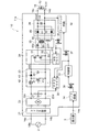
図5に表したように、照明装置100の電源回路104では、フィードバック回路32からのフィードバック信号と、制御部33からの調光信号とが、PFCドライバ30にも入力されている。なお、PFCドライバ30に入力される信号は、フィードバック信号と調光信号とのいずれか一方のみでもよい。
図6に表したように、照明装置110の電源回路114は、抵抗27、28を含む。抵抗27、28は、整流回路22の高電位端子22cと低電位端子22dとの間に直列に接続されている。電源回路114では、PFCドライバ30が、抵抗27、28の接続点に接続されている。これにより、PFCドライバ30には、整流回路22から出力される整流電圧を抵抗27、28で分圧した電圧が、入力電圧VINの検出電圧として入力される。
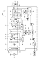
図7は、第3の実施形態に係る照明装置を模式的に表すブロック図である。
図7に表したように、照明装置120の電源回路124は、第1電源部81と、第2電源部82と、ドロッパ83と、をさらに含む。
図8は、コンデンサ53の発生電圧を模式的に表す。図8の横軸は、共振回路の共振周波数である。縦軸は、コンデンサ53に発生する電圧である。
図9に表したように、フィードバック回路32は、フィードバック制御部32aと、出力電圧検出部32bと、出力電流検出部32cと、を含む。
図10は、第4の実施形態に係る照明装置を模式的に表すブロック図である。
図10に表したように、照明装置130の電源回路134は、スイッチング素子84をさらに含む。スイッチング素子84は、電極84a〜84cを有する。電極84aは、第1電源部81に接続されている。電極84bは、PFCドライバ30及びHBドライバ31に接続されている。電極84cは、制御部33に接続されている。電極84cは、制御電極であり、電極84aと電極84bとの間に流れる電流を制御する。制御部33は、スイッチング素子84をオン・オフを制御する。すなわち、制御部33は、PFCドライバ30及びHBドライバ31に対する電力供給と電力供給の停止とを制御する。
図11は、第5の実施形態に係る照明装置を模式的に表すブロック図である。
図11に表したように、照明装置140には、操作部18が設けられている。操作部18は、照明装置140の外面に露出して設けられる。操作部18は、例えば、スライドレバーである。操作部18は、ロータリスイッチなどでもよい。照明装置140の電源回路144には、フィードバック回路32に可変抵抗98が設けられている。可変抵抗98は、差動増幅回路90の非反転入力端子に接続されている。また、可変抵抗98は、操作部18に物理的に接続されており、操作部18の操作に連動して抵抗値を変化させる。
Claims (4)
- 少なくとも1つのスイッチング素子を含み、前記スイッチング素子のオン・オフによって、直流電圧を交流電圧に変換するブリッジ回路と、
前記ブリッジ回路に接続された一次巻線と、前記一次巻線と磁気結合した二次巻線と、を含むトランスと、
前記二次巻線から出力される交流電圧を直流の出力電圧に変換して直流負荷に供給する整流平滑回路と、
前記スイッチング素子のオン・オフを制御するドライバと、
前記直流負荷に流れる出力電流の検出信号と、前記出力電圧の変動から得られる微分信号と、が入力され、前記検出信号と前記微分信号とを基に、前記ドライバをフィードバック制御するフィードバック回路と、
前記出力電圧から前記フィードバック回路に対応した駆動電圧を生成し、前記駆動電圧をフィードバック回路に供給する電源部と、
を備え、
前記フィードバック回路は、差動増幅回路と、前記整流平滑回路の高電位側の出力端子と前記差動増幅回路の一方の入力端子との間に設けられたコンデンサと、を含み、前記コンデンサを介して前記一方の入力端子に前記微分信号を入力するとともに、前記一方の入力端子に前記検出信号を入力し、前記差動増幅回路の他方の入力端子に基準電圧を入力し、前記一方の入力端子の電圧と前記他方の入力端子の電圧との差分に対応した電圧をフィードバック信号として前記ドライバに入力し、
前記ドライバは、前記フィードバック信号に応じて前記スイッチング素子のオン・オフを制御する電源回路。 - 前記フィードバック回路は、前記一方の入力端子と前記電源部の出力端子との間、及び、前記一方の入力端子と前記整流平滑回路の低電位側の出力端子との間の少なくとも一方に設けられた保護ダイオードをさらに含む請求項1記載の電源回路。
- 前記ドライバは、前記フィードバック回路によって過電圧が検出された場合に、所定電圧以下の前記出力電圧となるように、前記ブリッジ回路を制御する請求項1又は2に記載の電源回路。
- 照明負荷と、
前記照明負荷に電力を供給する請求項1〜3のいずれか1つに記載の電源回路と、
を備えた照明装置。
Priority Applications (4)
| Application Number | Priority Date | Filing Date | Title |
|---|---|---|---|
| JP2013202793A JP6233567B2 (ja) | 2013-09-27 | 2013-09-27 | 電源回路及び照明装置 |
| EP14155578.9A EP2854481A1 (en) | 2013-09-27 | 2014-02-18 | Power supply circuit and luminaire |
| US14/185,126 US20150091459A1 (en) | 2013-09-27 | 2014-02-20 | Power Supply Circuit and Luminaire |
| CN201410103055.5A CN104519637B (zh) | 2013-09-27 | 2014-03-19 | 电源电路及照明装置 |
Applications Claiming Priority (1)
| Application Number | Priority Date | Filing Date | Title |
|---|---|---|---|
| JP2013202793A JP6233567B2 (ja) | 2013-09-27 | 2013-09-27 | 電源回路及び照明装置 |
Publications (2)
| Publication Number | Publication Date |
|---|---|
| JP2015070697A JP2015070697A (ja) | 2015-04-13 |
| JP6233567B2 true JP6233567B2 (ja) | 2017-11-22 |
Family
ID=50112845
Family Applications (1)
| Application Number | Title | Priority Date | Filing Date |
|---|---|---|---|
| JP2013202793A Active JP6233567B2 (ja) | 2013-09-27 | 2013-09-27 | 電源回路及び照明装置 |
Country Status (4)
| Country | Link |
|---|---|
| US (1) | US20150091459A1 (ja) |
| EP (1) | EP2854481A1 (ja) |
| JP (1) | JP6233567B2 (ja) |
| CN (1) | CN104519637B (ja) |
Families Citing this family (5)
| Publication number | Priority date | Publication date | Assignee | Title |
|---|---|---|---|---|
| US9960665B2 (en) * | 2015-12-02 | 2018-05-01 | Astec International Limited | Power supplies having a single isolation device for feedback and fault detection |
| KR20170071229A (ko) | 2015-12-15 | 2017-06-23 | 엘지이노텍 주식회사 | 조광기와 드라이버가 전기적 절연 구조를 가지는 조명 장치 및 시스템 |
| CN107197185B (zh) * | 2017-07-26 | 2020-03-31 | 深圳市华星光电技术有限公司 | 一种用于液晶电视的电源 |
| CN107592704B (zh) * | 2017-09-29 | 2019-09-20 | 深圳市华星光电技术有限公司 | 一种用于液晶电视的恒流电路 |
| CN111614260B (zh) * | 2019-06-25 | 2022-05-03 | 南京拓途电子有限公司 | 一种低频下可靠驱动线圈负载的电路 |
Family Cites Families (15)
| Publication number | Priority date | Publication date | Assignee | Title |
|---|---|---|---|---|
| US3940682A (en) * | 1973-10-15 | 1976-02-24 | General Electric Company | Rectifier circuits using transistors as rectifying elements |
| US6784624B2 (en) * | 2001-12-19 | 2004-08-31 | Nicholas Buonocunto | Electronic ballast system having emergency lighting provisions |
| US6664660B2 (en) * | 2002-01-04 | 2003-12-16 | Delta Electronics, Inc. | Parallel power supply system with over-voltage protection circuit |
| CN1879453B (zh) * | 2003-11-13 | 2010-06-23 | 皇家飞利浦电子股份有限公司 | 具有亮度和颜色控制的谐振电源led控制电路 |
| JP2005168188A (ja) * | 2003-12-03 | 2005-06-23 | Sony Corp | スイッチング電源回路 |
| JP2005176535A (ja) * | 2003-12-12 | 2005-06-30 | Keyence Corp | スイッチング電源装置 |
| JP2008187821A (ja) * | 2007-01-30 | 2008-08-14 | Matsushita Electric Works Ltd | 絶縁型ac−dcコンバータおよびそれを用いるled用直流電源装置 |
| JP2009278727A (ja) * | 2008-05-13 | 2009-11-26 | Diamond Electric Mfg Co Ltd | モータ制御装置 |
| JP2010086943A (ja) * | 2008-09-04 | 2010-04-15 | Toshiba Lighting & Technology Corp | Led点灯装置および照明器具 |
| US8773111B2 (en) * | 2010-02-25 | 2014-07-08 | Fuji Electric Co., Ltd. | Current estimation circuit |
| CN102457049B (zh) * | 2010-10-29 | 2014-07-02 | 登丰微电子股份有限公司 | 电源转换控制器及发光二极管驱动电路 |
| KR101275399B1 (ko) * | 2010-12-13 | 2013-06-17 | 삼성전기주식회사 | 발광 다이오드 구동 장치 |
| US9343988B2 (en) * | 2011-08-05 | 2016-05-17 | Triune Systems, LLC | Current mode regulator |
| JP5971578B2 (ja) * | 2011-08-22 | 2016-08-17 | パナソニックIpマネジメント株式会社 | 点灯装置、前照灯点灯装置及びそれを用いた前照灯並びに車両 |
| JP5828273B2 (ja) * | 2011-12-01 | 2015-12-02 | 富士電機株式会社 | スイッチング電源装置 |
-
2013
- 2013-09-27 JP JP2013202793A patent/JP6233567B2/ja active Active
-
2014
- 2014-02-18 EP EP14155578.9A patent/EP2854481A1/en not_active Withdrawn
- 2014-02-20 US US14/185,126 patent/US20150091459A1/en not_active Abandoned
- 2014-03-19 CN CN201410103055.5A patent/CN104519637B/zh not_active Expired - Fee Related
Also Published As
| Publication number | Publication date |
|---|---|
| EP2854481A1 (en) | 2015-04-01 |
| US20150091459A1 (en) | 2015-04-02 |
| CN104519637A (zh) | 2015-04-15 |
| CN104519637B (zh) | 2018-09-18 |
| JP2015070697A (ja) | 2015-04-13 |
Similar Documents
| Publication | Publication Date | Title |
|---|---|---|
| JP6233568B2 (ja) | 電源回路及び照明装置 | |
| JP2015070696A (ja) | 電源回路及び照明装置 | |
| JP5435912B2 (ja) | 電源装置及び照明装置 | |
| JP6283988B2 (ja) | 電源回路及び照明装置 | |
| US20120319610A1 (en) | Led lighting apparatus | |
| JP6233567B2 (ja) | 電源回路及び照明装置 | |
| JP2011100621A (ja) | 光源点灯装置および照明装置 | |
| JP6249167B2 (ja) | Led点灯装置及びled照明装置 | |
| JP2014110696A (ja) | 電源装置及び照明装置 | |
| JP6593660B2 (ja) | 電源回路及び照明装置 | |
| JP6186918B2 (ja) | Led点灯回路及びled照明装置 | |
| JP6347411B2 (ja) | 電源装置及び照明装置 | |
| JP6603763B2 (ja) | 照明システム | |
| JP5429021B2 (ja) | Led駆動装置 | |
| CN204206550U (zh) | 电源电路以及照明装置 | |
| JP2015186337A (ja) | 電源回路及び照明装置 | |
| JP2016067087A (ja) | 電源装置及び照明装置 | |
| EP3133902B1 (en) | Single-stage power factor corrected led driver circuit | |
| JP6256755B2 (ja) | 点灯装置及び照明装置 | |
| JP2018142551A (ja) | 電源装置及び照明装置 | |
| JP6341034B2 (ja) | 電源回路及び照明装置 | |
| JP6778899B2 (ja) | 点灯装置及び照明器具 | |
| JP2015210974A (ja) | 点灯装置及び照明装置 | |
| CN104254171A (zh) | 用于发光二极管(led)照明系统的驱动器 | |
| JP2015195093A (ja) | 電源装置および照明装置 |
Legal Events
| Date | Code | Title | Description |
|---|---|---|---|
| A621 | Written request for application examination |
Free format text: JAPANESE INTERMEDIATE CODE: A621 Effective date: 20160322 |
|
| A131 | Notification of reasons for refusal |
Free format text: JAPANESE INTERMEDIATE CODE: A131 Effective date: 20170314 |
|
| A977 | Report on retrieval |
Free format text: JAPANESE INTERMEDIATE CODE: A971007 Effective date: 20170315 |
|
| A521 | Written amendment |
Free format text: JAPANESE INTERMEDIATE CODE: A523 Effective date: 20170512 |
|
| TRDD | Decision of grant or rejection written | ||
| A01 | Written decision to grant a patent or to grant a registration (utility model) |
Free format text: JAPANESE INTERMEDIATE CODE: A01 Effective date: 20170927 |
|
| A61 | First payment of annual fees (during grant procedure) |
Free format text: JAPANESE INTERMEDIATE CODE: A61 Effective date: 20171010 |
|
| R151 | Written notification of patent or utility model registration |
Ref document number: 6233567 Country of ref document: JP Free format text: JAPANESE INTERMEDIATE CODE: R151 |