JP6731496B2 - Multi-petal mounting member for ostomy pouch - Google Patents
Multi-petal mounting member for ostomy pouch Download PDFInfo
- Publication number
- JP6731496B2 JP6731496B2 JP2018559882A JP2018559882A JP6731496B2 JP 6731496 B2 JP6731496 B2 JP 6731496B2 JP 2018559882 A JP2018559882 A JP 2018559882A JP 2018559882 A JP2018559882 A JP 2018559882A JP 6731496 B2 JP6731496 B2 JP 6731496B2
- Authority
- JP
- Japan
- Prior art keywords
- double
- sided adhesive
- petal
- adhesive substrate
- flexible plastic
- Prior art date
- Legal status (The legal status is an assumption and is not a legal conclusion. Google has not performed a legal analysis and makes no representation as to the accuracy of the status listed.)
- Active
Links
Images


Classifications
-
- A—HUMAN NECESSITIES
- A61—MEDICAL OR VETERINARY SCIENCE; HYGIENE
- A61F—FILTERS IMPLANTABLE INTO BLOOD VESSELS; PROSTHESES; DEVICES PROVIDING PATENCY TO, OR PREVENTING COLLAPSING OF, TUBULAR STRUCTURES OF THE BODY, e.g. STENTS; ORTHOPAEDIC, NURSING OR CONTRACEPTIVE DEVICES; FOMENTATION; TREATMENT OR PROTECTION OF EYES OR EARS; BANDAGES, DRESSINGS OR ABSORBENT PADS; FIRST-AID KITS
- A61F5/00—Orthopaedic methods or devices for non-surgical treatment of bones or joints; Nursing devices ; Anti-rape devices
- A61F5/44—Devices worn by the patient for reception of urine, faeces, catamenial or other discharge; Colostomy devices
- A61F5/445—Colostomy, ileostomy or urethrostomy devices
- A61F2005/4483—Convex pressure ring
-
- A—HUMAN NECESSITIES
- A61—MEDICAL OR VETERINARY SCIENCE; HYGIENE
- A61F—FILTERS IMPLANTABLE INTO BLOOD VESSELS; PROSTHESES; DEVICES PROVIDING PATENCY TO, OR PREVENTING COLLAPSING OF, TUBULAR STRUCTURES OF THE BODY, e.g. STENTS; ORTHOPAEDIC, NURSING OR CONTRACEPTIVE DEVICES; FOMENTATION; TREATMENT OR PROTECTION OF EYES OR EARS; BANDAGES, DRESSINGS OR ABSORBENT PADS; FIRST-AID KITS
- A61F5/00—Orthopaedic methods or devices for non-surgical treatment of bones or joints; Nursing devices ; Anti-rape devices
- A61F5/44—Devices worn by the patient for reception of urine, faeces, catamenial or other discharge; Colostomy devices
- A61F5/443—Devices worn by the patient for reception of urine, faeces, catamenial or other discharge; Colostomy devices having adhesive seals for securing to the body, e.g. of hydrocolloid type seals, e.g. gels, starches, karaya gums
Landscapes
- Health & Medical Sciences (AREA)
- Epidemiology (AREA)
- Nursing (AREA)
- Orthopedic Medicine & Surgery (AREA)
- Engineering & Computer Science (AREA)
- Biomedical Technology (AREA)
- Heart & Thoracic Surgery (AREA)
- Vascular Medicine (AREA)
- Life Sciences & Earth Sciences (AREA)
- Animal Behavior & Ethology (AREA)
- General Health & Medical Sciences (AREA)
- Public Health (AREA)
- Veterinary Medicine (AREA)
- Orthopedics, Nursing, And Contraception (AREA)
- Materials For Medical Uses (AREA)
Description
本発明は、概して、オストミーパウチのための多ペタル装着部材に関し、より詳細には、(a)中心本体部分、包囲周縁、および外側周辺部を備える柔軟なプラスチック部材と、(b)第1の面、反対側の第2の面、および外側周辺部を備える第1の両面接着剤基材と、(c)第1の面、反対側の第2の面、および多ペタル外側周辺部を備える第2の両面接着剤基材と、(d)第1の面、反対側の第2の面、および多ペタル外側周辺部を備える接着剤皮膚障壁部材とを備え、(i)第1の両面接着剤基材の外側周辺部は、大きさおよび形が柔軟なプラスチック部材の外側周辺部に実質的に一致実質的に一致し、(ii)第2の両面接着剤基材の多ペタル外側周辺部は、柔軟なプラスチック部材の外側周辺部より大きい大きさを有すると共に、第2の両面接着剤基材から径方向に延び、第2の両面接着剤基材の周りに均等に分配され、第2の両面接着剤基材から径方向に拡がる切り込みによって分離される2〜8枚のペタルに等しい形を有し、(iii)接着剤皮膚障壁部材の多ペタル外側周辺部は、大きさおよび形が第2の両面接着剤基材の多ペタル外側周辺部に実質的に一致実質的に一致する、オストミーパウチのための多ペタル装着部材に関する。 The present invention relates generally to a multi-petal mounting member for an ostomy pouch, and more particularly, (a) a flexible plastic member having a central body portion, a surrounding perimeter, and an outer perimeter, and (b) a first plastic member. Surface, an opposite second surface, and a first double-sided adhesive substrate with an outer perimeter, and (c) a first surface, an opposite second surface, and a multi-petal outer perimeter. A second double-sided adhesive substrate, and (d) an adhesive skin barrier member having a first surface, an opposite second surface, and a multi-petal outer perimeter, and (i) a first double-sided surface. The outer perimeter of the adhesive substrate substantially matches and substantially matches the outer perimeter of the flexible plastic member in size and shape, and (ii) a multi-petal outer perimeter of the second double-sided adhesive substrate. The portion has a size larger than the outer periphery of the flexible plastic member and extends radially from the second double-sided adhesive substrate and is evenly distributed about the second double-sided adhesive substrate. 2 has a shape equal to 2-8 petals separated by a radially extending notch from the double-sided adhesive substrate, and (iii) the multi-petal outer perimeter of the adhesive skin barrier member is sized and shaped. Substantially coincides with and substantially coincides with a multi-petal outer perimeter of the second double-sided adhesive substrate.
オストメイトは、体内排泄物の排出を可能にするオストミーと呼ばれる開口を身体に作り出すための手術を受けた人である。手術は、結腸、小腸、または尿管などの器官の端に対応し、腹壁を貫通して突出し、体内排泄物が排出されるのに通るストーマの準備を含む。体内排泄物の回収のために、ストーマ周囲皮膚表面と呼ばれるオストミーの周りの皮膚表面にオストミー器具が付着され得る。 An ostomate is a person who has had surgery to create an opening in the body called an ostomy that allows the elimination of bodily waste. Surgery involves the preparation of a stoma that corresponds to the edge of an organ such as the colon, small intestine, or ureter, projects through the abdominal wall, and through which body exudates are expelled. Ostomy devices can be attached to the skin surface around the ostomy, called the peristomal skin surface, for the collection of bodily waste.
さまざまな種類のオストミー器具が開示されている。例えば、Fentonの米国特許第6,790,200号は、ストーマ受け入れ門部を有するオストミーパウチを含むオストミー器具および装着円板を開示している。装着円板は、門部の周りで封止され、凸状の中心本体部分と包囲する環状の周縁とを有する柔軟なプラスチック円板を備える。周縁の外径に対応する外径を有する第1の発泡体円板は、プラスチック円板に接着剤で接着される。第2の発泡体円板は、第1の発泡体円板の接着剤面に接着され、プラスチック円板より大きい外径を有する。第2の発泡体円板の外径に対応する外径を有する親水コロイド皮膚遮蔽円板が、第2の円板の接着剤面に接着剤で接着される。 Various types of ostomy appliances have been disclosed. For example, Fenton US Pat. No. 6,790,200 discloses an ostomy appliance and mounting disc including an ostomy pouch having a stoma receiving portal. The mounting disc comprises a flexible plastic disc that is sealed around the portal and has a convex central body portion and an annular periphery that surrounds it. A first foam disc having an outer diameter corresponding to the outer diameter of the peripheral edge is glued to the plastic disc. The second foam disc is bonded to the adhesive side of the first foam disc and has a larger outer diameter than the plastic disc. A hydrocolloid skin-shielding disc having an outer diameter that corresponds to the outer diameter of the second foam disc is glued to the adhesive side of the second disc.
同じく例として、Fentonの米国特許第8,328,779号は、オストミーパウチのための装着組立体を開示している。組立体は、オストメイトのストーマ周囲皮膚表面に接着されるように適応された一方の側における接着剤被覆を有する本体フランジを備える。直径方向に互いと対向した輪がフランジの縁から突出し、ポケットを形成している。フランジの輪のポケットと協働する直径方向に互いと対向した輪を有するしっかりとした柔軟な環体によって包囲されたストーマ受入開口を有するオストミーパウチも開示されている。接着剤被覆が柔軟な環体とフランジとに設けられている。柔軟な環体における輪がフランジにおけるポケットと位置合わせされるとき、フランジおよび環体はパウチを本体フランジに付着させるために接着剤で結合させられ得る。 Also by way of example, Fenton US Pat. No. 8,328,779 discloses a mounting assembly for an ostomy pouch. The assembly comprises a body flange having an adhesive coating on one side adapted to adhere to the ostomate's peristomal skin surface. The diametrically opposed rings project from the edges of the flange and form pockets. Also disclosed is an ostomy pouch having a stoma receiving opening surrounded by a rigid, flexible annulus having diametrically opposed rings cooperating with flanged ring pockets. An adhesive coating is provided on the flexible annulus and the flange. When the annulus in the flexible annulus is aligned with the pocket in the flange, the flange and annulus may be adhesively bonded to attach the pouch to the body flange.
オストミー器具をできるだけ快適に使用するために、オストミー器具を改善することと、付属品を開発することに多くの労力が注ぎ込まれてきた。しかしながら、オストメイトは、適切なフィットを提供するオストミー器具を最初に特定することがなおも難しいことがあり、別のフィットは適切ではないという懸念に基づいて、別のオストミー器具を試そうとしないこともある。 Much effort has been devoted to improving ostomy appliances and developing accessories in order to use the ostomy appliances as comfortably as possible. However, ostomates may still find it difficult to first identify an ostomy device that provides a proper fit, and may not try another ostomy device based on the concern that another fit is not appropriate. is there.
したがって、向上されたフィットとオストメイトに対する増加した快適性とを概して提供できるオストミー器具に対する要求が存在する。 Therefore, there is a need for ostomy appliances that can generally provide improved fit and increased comfort for ostomate.
オストミーパウチのための多ペタル装着部材が開示される。多ペタル装着部材は、(a)中心本体部分、包囲周縁、および外側周辺部を備える柔軟なプラスチック部材と、(b)第1の面、反対側の第2の面、および外側周辺部を備える第1の両面接着剤基材と、(c)第1の面、反対側の第2の面、および多ペタル外側周辺部を備える第2の両面接着剤基材と、(d)第1の面、反対側の第2の面、および多ペタル外側周辺部を備える接着剤皮膚障壁部材とを備える。第1の両面接着剤基材の外側周辺部は、大きさおよび形が柔軟なプラスチック部材の外側周辺部に実質的に一致実質的に一致する。第1の両面接着剤基材の第2の面は、柔軟なプラスチック部材の中心本体部分および包囲周縁に接着される。第2の両面接着剤基材の多ペタル外側周辺部は、柔軟なプラスチック部材の外側周辺部より大きい大きさを有すると共に、第2の両面接着剤基材から径方向に延び、第2の両面接着剤基材の周りに均等に分配され、第2の両面接着剤基材から径方向に拡がる切り込みによって分離される2〜8枚のペタルに等しい形を有する。第2の両面接着剤基材の第2の面は、第1の両面接着剤基材の第1の面に接着される。接着剤皮膚障壁部材の多ペタル外側周辺部は、大きさおよび形が第2の両面接着剤基材の多ペタル外側周辺部に実質的に一致実質的に一致する。接着剤皮膚障壁部材の第2の面は、第2の両面接着剤基材の第1の面に接着される。 A multiple petal mounting member for an ostomy pouch is disclosed. The multi-petal mounting member comprises: (a) a flexible plastic member having a central body portion, a surrounding perimeter, and an outer perimeter; and (b) a first surface, an opposite second surface, and an outer perimeter. A first double-sided adhesive substrate; (c) a second double-sided adhesive substrate having a first side, an opposite second side, and a multi-petal outer perimeter; and (d) a first side. A surface, an opposite second surface, and an adhesive skin barrier member with a multi-petal outer perimeter. The outer perimeter of the first double-sided adhesive substrate substantially matches and substantially matches the outer perimeter of the flexible plastic member in size and shape. The second side of the first double-sided adhesive substrate is adhered to the central body portion and the surrounding perimeter of the flexible plastic member. The multi-petal outer perimeter of the second double-sided adhesive substrate has a larger size than the outer perimeter of the flexible plastic member and extends radially from the second double-sided adhesive substrate to form a second double-sided adhesive substrate. It has a shape that is evenly distributed around the adhesive substrate and is equivalent to 2-8 petals separated from the second double-sided adhesive substrate by radially extending notches. The second side of the second double-sided adhesive substrate is bonded to the first side of the first double-sided adhesive substrate. The multi-petal outer perimeter of the adhesive skin barrier member substantially matches and substantially matches in size and shape to the multi-petal outer perimeter of the second double-sided adhesive substrate. The second side of the adhesive skin barrier member is adhered to the first side of the second double sided adhesive substrate.
一部の例によれば、(i)柔軟なプラスチック部材の中心本体部分は第1の面および反対側の第2の面を有し、(ii)中心本体部分の第1の面は凸状であり、(iii)中心本体部分の第2の面は凹状であり、(iv)第1の両面接着剤基材の第2の面は、中心本体部分の凸状の第1の面において中心本体部分に接着される。 According to some examples, (i) the central body portion of the flexible plastic member has a first surface and an opposite second surface, and (ii) the first surface of the central body portion is convex. And (iii) the second surface of the central body portion is concave, and (iv) the second surface of the first double-sided adhesive substrate is centered on the convex first surface of the central body portion. It is glued to the body.
同じく一部の例によれば、(i)柔軟なプラスチック部材の中心本体部分は第1の面および反対側の第2の面を有し、(ii)中心本体部分の第1の面は平坦であり、(iii)中心本体部分の第2の面は平坦であり、(iv)第1の両面接着剤基材の第2の面は、中心本体部分の平坦な第1の面において中心本体部分に接着される。 Also according to some examples, (i) the central body portion of the flexible plastic member has a first surface and an opposite second surface, and (ii) the first surface of the central body portion is flat. And (iii) the second surface of the central body portion is flat, and (iv) the second surface of the first double-sided adhesive substrate is the central body at the flat first surface of the central body portion. It is glued to the part.
同じく一部の例によれば、2〜8枚のペタルは、第2の両面接着剤基材から径方向外向きに初めに増加し次いで減少する幅を各々有する。 Also according to some examples, the two to eight petals each have a width that increases first radially outward and then decreases from the second double-sided adhesive substrate.
同じく一部の例によれば、第2の両面接着剤基材は最大半径を有し、第2の両面接着剤基材の多ペタル外側周辺部の少なくとも50%は第2の両面接着剤基材の最大半径まで延びている。 Also according to some examples, the second double-sided adhesive substrate has a maximum radius and at least 50% of the multi-petal outer perimeter of the second double-sided adhesive substrate is the second double-sided adhesive substrate. It extends to the maximum radius of the material.
同じく一部の例によれば、第2の両面接着剤基材の多ペタル外側周辺部の形が3〜6枚のペタルに等しい。 Also according to some examples, the shape of the multi-petal outer perimeter of the second double-sided adhesive substrate is equal to 3-6 petals.
同じく一部の例によれば、柔軟なプラスチック部材の包囲周縁は実質的に環状である。 Also according to some examples, the surrounding perimeter of the flexible plastic member is substantially annular.
同じく一部の例によれば、柔軟なプラスチック部材は装着輪をさらに備え、装着輪は、直径方向に反対と対向し、包囲周縁から、第2の両面接着剤基材の多ペタル外側周辺部以内まで、および、接着剤皮膚障壁部材の多ペタル外側周辺部以内まで径方向外向きに延びる。 Also according to some examples, the flexible plastic member further comprises a mounting wheel, the mounting wheel being diametrically opposite, from the surrounding perimeter, to a multi-petal outer perimeter of the second double-sided adhesive substrate. Extends radially outwardly to within and within the multipetal outer perimeter of the adhesive skin barrier member.
同じく一部の例によれば、接着剤皮膚障壁部材はエラストマ親水コロイド混合物を含む。 Also according to some examples, the adhesive skin barrier member comprises an elastomer hydrocolloid mixture.
同じく一部の例によれば、第1の両面接着剤基材は発泡体層を備える。 Also according to some examples, the first double-sided adhesive substrate comprises a foam layer.
同じく一部の例によれば、第2の両面接着剤基材は発泡体層を備える。 Also according to some examples, the second double-sided adhesive substrate comprises a foam layer.
同じく一部の例によれば、多ペタル装着部材は、除去可能な保護膜をさらに備え、除去可能な保護膜は接着剤皮膚障壁部材の第1の面を覆う。 Also according to some examples, the multi-petal attachment member further comprises a removable overcoat, the removable overcoat covering the first surface of the adhesive skin barrier member.
同じく一部の例によれば、柔軟なプラスチック部材、第1の両面接着剤基材、第2の両面接着剤基材、および接着剤皮膚障壁部材の各々は、中心に位置決めされてそれらを貫いて延びるストーマ入口門部を有する。 Also according to some examples, each of the flexible plastic member, the first double-sided adhesive substrate, the second double-sided adhesive substrate, and the adhesive skin barrier member are centrally positioned and pierce them. It has a stoma entrance gate that extends through.
オストミー器具も開示される。オストミー器具は多ペタル装着部材を備える。オストミー器具はオストミーパウチも備える。 An ostomy appliance is also disclosed. The ostomy appliance comprises a multi-petal mounting member. The ostomy appliance also includes an ostomy pouch.
多ペタル装着部材は、(a)中心本体部分、包囲周縁、および外側周辺部を備える柔軟なプラスチック部材と、(b)第1の面、反対側の第2の面、および外側周辺部を備える第1の両面接着剤基材と、(c)第1の面、反対側の第2の面、および多ペタル外側周辺部を備える第2の両面接着剤基材と、(d)第1の面、反対側の第2の面、および多ペタル外側周辺部を備える接着剤皮膚障壁部材とを備える。第1の両面接着剤基材の外側周辺部は、大きさおよび形が柔軟なプラスチック部材の外側周辺部に実質的に一致実質的に一致する。第1の両面接着剤基材の第2の面は、柔軟なプラスチック部材の中心本体部分および包囲周縁に接着される。第2の両面接着剤基材の多ペタル外側周辺部は、柔軟なプラスチック部材の外側周辺部より大きい大きさを有すると共に、第2の両面接着剤基材から径方向に延び、第2の両面接着剤基材の周りに均等に分配され、第2の両面接着剤基材から径方向に拡がる切り込みによって分離される2〜8枚のペタルに等しい形を有する。第2の両面接着剤基材の第2の面は、第1の両面接着剤基材の第1の面に接着される。接着剤皮膚障壁部材の多ペタル外側周辺部は、大きさおよび形が第2の両面接着剤基材の多ペタル外側周辺部に実質的に一致実質的に一致する。接着剤皮膚障壁部材の第2の面は、第2の両面接着剤基材の第1の面に接着される。 The multi-petal mounting member comprises: (a) a flexible plastic member having a central body portion, a surrounding perimeter, and an outer perimeter; and (b) a first surface, an opposite second surface, and an outer perimeter. A first double-sided adhesive substrate; (c) a second double-sided adhesive substrate having a first side, an opposite second side, and a multi-petal outer perimeter; and (d) a first side. A surface, an opposite second surface, and an adhesive skin barrier member with a multi-petal outer perimeter. The outer perimeter of the first double-sided adhesive substrate substantially matches and substantially matches the outer perimeter of the flexible plastic member in size and shape. The second side of the first double-sided adhesive substrate is adhered to the central body portion and the surrounding perimeter of the flexible plastic member. The multi-petal outer perimeter of the second double-sided adhesive substrate has a larger size than the outer perimeter of the flexible plastic member and extends radially from the second double-sided adhesive substrate to form a second double-sided adhesive substrate. It has a shape that is evenly distributed around the adhesive substrate and is equivalent to 2-8 petals separated from the second double-sided adhesive substrate by radially extending notches. The second side of the second double-sided adhesive substrate is bonded to the first side of the first double-sided adhesive substrate. The multi-petal outer perimeter of the adhesive skin barrier member substantially matches and substantially matches in size and shape to the multi-petal outer perimeter of the second double-sided adhesive substrate. The second side of the adhesive skin barrier member is adhered to the first side of the second double sided adhesive substrate.
オストミーパウチは、プラスチック膜の近位シートとプラスチック膜の遠位シートとを備え、近位シートと遠位シートとがそれぞれの周囲で封止されてオストミーパウチを形成する。近位シートは、内側周辺部と、内側周辺部を包囲する領域とを有するストーマ入口門部を備える。柔軟なプラスチック部材の包囲周縁は内側周辺部をさらに備える。柔軟なプラスチック部材の包囲周縁の内側周辺部は、大きさおよび形が近位シートのストーマ入口門部の内側周辺部に実質的に一致実質的に一致する。柔軟なプラスチック部材の包囲周縁は、近位シートの内側周辺部を包囲する領域に封止される。 The ostomy pouch comprises a proximal sheet of plastic membrane and a distal sheet of plastic membrane, the proximal sheet and the distal sheet being sealed around each other to form an ostomy pouch. The proximal seat comprises a stoma inlet portal having an inner perimeter and a region surrounding the inner perimeter. The surrounding perimeter of the flexible plastic member further comprises an inner perimeter. The inner perimeter of the surrounding perimeter of the flexible plastic member substantially conforms in size and shape to the inner perimeter of the stoma inlet portal of the proximal sheet. The surrounding perimeter of the flexible plastic member is sealed to the area surrounding the inner perimeter of the proximal sheet.
一部の例によれば、(i)柔軟なプラスチック部材の中心本体部分は第1の面および反対側の第2の面を有し、(ii)中心本体部分の第1の面は凸状であり、(iii)中心本体部分の第2の面は凹状であり、(iv)第1の両面接着剤基材の第2の面は、中心本体部分の凸状の第1の面において中心本体部分に接着される。 According to some examples, (i) the central body portion of the flexible plastic member has a first surface and an opposite second surface, and (ii) the first surface of the central body portion is convex. And (iii) the second surface of the central body portion is concave, and (iv) the second surface of the first double-sided adhesive substrate is centered on the convex first surface of the central body portion. It is glued to the body.
同じく一部の例によれば、(i)柔軟なプラスチック部材の中心本体部分は第1の面および反対側の第2の面を有し、(ii)中心本体部分の第1の面は平坦であり、(iii)中心本体部分の第2の面は平坦であり、(iv)第1の両面接着剤基材の第2の面は、中心本体部分の平坦な第1の面において中心本体部分に接着される。 Also according to some examples, (i) the central body portion of the flexible plastic member has a first surface and an opposite second surface, and (ii) the first surface of the central body portion is flat. And (iii) the second surface of the central body portion is flat, and (iv) the second surface of the first double-sided adhesive substrate is the central body at the flat first surface of the central body portion. It is glued to the part.
同じく一部の例によれば、2〜8枚のペタルは、第2の両面接着剤基材から径方向外向きに初めに増加し次いで減少する幅を各々有する。 Also according to some examples, the two to eight petals each have a width that increases first radially outward and then decreases from the second double-sided adhesive substrate.
同じく一部の例によれば、第2の両面接着剤基材は最大半径を有し、第2の両面接着剤基材の多ペタル外側周辺部の少なくとも50%は第2の両面接着剤基材の最大半径まで延びている。 Also according to some examples, the second double-sided adhesive substrate has a maximum radius and at least 50% of the multi-petal outer perimeter of the second double-sided adhesive substrate is the second double-sided adhesive substrate. It extends to the maximum radius of the material.
同じく一部の例によれば、第2の両面接着剤基材の多ペタル外側周辺部の形が3〜6枚のペタルに等しい。 Also according to some examples, the shape of the multi-petal outer perimeter of the second double-sided adhesive substrate is equal to 3-6 petals.
同じく一部の例によれば、柔軟なプラスチック部材の包囲周縁は実質的に環状である。 Also according to some examples, the surrounding perimeter of the flexible plastic member is substantially annular.
同じく一部の例によれば、柔軟なプラスチック部材は装着輪をさらに備え、装着輪は、直径方向に反対と対向し、包囲周縁から、第2の両面接着剤基材の多ペタル外側周辺部以内まで、および、接着剤皮膚障壁部材の多ペタル外側周辺部以内まで径方向外向きに延びる。 Also according to some examples, the flexible plastic member further comprises a mounting wheel, the mounting wheel being diametrically opposite, from the surrounding perimeter, to a multi-petal outer perimeter of the second double-sided adhesive substrate. Extends radially outwardly to within and within the multipetal outer perimeter of the adhesive skin barrier member.
同じく一部の例によれば、接着剤皮膚障壁部材はエラストマ親水コロイド混合物を含む。 Also according to some examples, the adhesive skin barrier member comprises an elastomer hydrocolloid mixture.
同じく一部の例によれば、第1の両面接着剤基材は発泡体層を備える。 Also according to some examples, the first double-sided adhesive substrate comprises a foam layer.
同じく一部の例によれば、第2の両面接着剤基材は発泡体層を備える。 Also according to some examples, the second double-sided adhesive substrate comprises a foam layer.
同じく一部の例によれば、多ペタル装着部材は、除去可能な保護膜をさらに備え、除去可能な保護膜は接着剤皮膚障壁部材の第1の面を覆う。 Also according to some examples, the multi-petal attachment member further comprises a removable overcoat, the removable overcoat covering the first surface of the adhesive skin barrier member.
同じく一部の例によれば、柔軟なプラスチック部材、第1の両面接着剤基材、第2の両面接着剤基材、および接着剤皮膚障壁部材の各々は、中心に位置決めされてそれらを貫いて延びるストーマ入口門部を有する。 Also according to some examples, each of the flexible plastic member, the first double-sided adhesive substrate, the second double-sided adhesive substrate, and the adhesive skin barrier member are centrally positioned and pierce them. It has a stoma entrance gate that extends through.
同じく開示されるのは、オストメイトのストーマ周囲皮膚表面においてオストミー器具をオストメイトに接着する方法である。方法によれば、オストミー器具は多ペタル装着部材を備える。オストミー器具はオストミーパウチも備える。 Also disclosed is a method of adhering an ostomy device to an ostomate at the peristomal skin surface of the ostomate. According to the method, the ostomy appliance comprises a multi-petal mounting member. The ostomy appliance also includes an ostomy pouch.
多ペタル装着部材は、(a)中心本体部分、包囲周縁、および外側周辺部を備える柔軟なプラスチック部材と、(b)第1の面、反対側の第2の面、および外側周辺部を備える第1の両面接着剤基材と、(c)第1の面、反対側の第2の面、および多ペタル外側周辺部を備える第2の両面接着剤基材と、(d)第1の面、反対側の第2の面、および多ペタル外側周辺部を備える接着剤皮膚障壁部材とを備える。第1の両面接着剤基材の外側周辺部は、大きさおよび形が柔軟なプラスチック部材の外側周辺部に実質的に一致実質的に一致する。第1の両面接着剤基材の第2の面は、柔軟なプラスチック部材の中心本体部分および包囲周縁に接着される。第2の両面接着剤基材の多ペタル外側周辺部は、柔軟なプラスチック部材の外側周辺部より大きい大きさを有すると共に、第2の両面接着剤基材から径方向に延び、第2の両面接着剤基材の周りに均等に分配され、第2の両面接着剤基材から径方向に拡がる切り込みによって分離される2〜8枚のペタルに等しい形を有する。第2の両面接着剤基材の第2の面は、第1の両面接着剤基材の第1の面に接着される。接着剤皮膚障壁部材の多ペタル外側周辺部は、大きさおよび形が第2の両面接着剤基材の多ペタル外側周辺部に実質的に一致実質的に一致する。接着剤皮膚障壁部材の第2の面は、第2の両面接着剤基材の第1の面に接着される。 The multi-petal mounting member comprises: (a) a flexible plastic member having a central body portion, a surrounding perimeter, and an outer perimeter; and (b) a first surface, an opposite second surface, and an outer perimeter. A first double-sided adhesive substrate; (c) a second double-sided adhesive substrate having a first side, an opposite second side, and a multi-petal outer perimeter; and (d) a first side. A surface, an opposite second surface, and an adhesive skin barrier member with a multi-petal outer perimeter. The outer perimeter of the first double-sided adhesive substrate substantially matches and substantially matches the outer perimeter of the flexible plastic member in size and shape. The second side of the first double-sided adhesive substrate is adhered to the central body portion and the surrounding perimeter of the flexible plastic member. The multi-petal outer perimeter of the second double-sided adhesive substrate has a larger size than the outer perimeter of the flexible plastic member and extends radially from the second double-sided adhesive substrate to form a second double-sided adhesive substrate. It has a shape that is evenly distributed around the adhesive substrate and is equivalent to 2-8 petals separated from the second double-sided adhesive substrate by radially extending notches. The second side of the second double-sided adhesive substrate is bonded to the first side of the first double-sided adhesive substrate. The multi-petal outer perimeter of the adhesive skin barrier member substantially matches and substantially matches in size and shape to the multi-petal outer perimeter of the second double-sided adhesive substrate. The second side of the adhesive skin barrier member is adhered to the first side of the second double sided adhesive substrate.
多ペタル装着部材は、除去可能な保護膜をさらに備え、除去可能な保護膜は接着剤皮膚障壁部材の第1の面を覆う。 The multi-petal attachment member further comprises a removable overcoat, the removable overcoat covering the first surface of the adhesive skin barrier member.
柔軟なプラスチック部材、第1の両面接着剤基材、第2の両面接着剤基材、および接着剤皮膚障壁部材の各々は、中心に位置決めされてそれらを貫いて延びるストーマ入口門部を有する。 The flexible plastic member, the first double-sided adhesive substrate, the second double-sided adhesive substrate, and the adhesive skin barrier member each have a stoma inlet portal centrally positioned and extending therethrough.
オストミーパウチは、プラスチック膜の近位シートとプラスチック膜の遠位シートとを備え、近位シートと遠位シートとがそれぞれの周囲で封止されてオストミーパウチを形成する。近位シートは、内側周辺部と、内側周辺部を包囲する領域とを有するストーマ入口門部を備える。柔軟なプラスチック部材の包囲周縁は内側周辺部をさらに備える。柔軟なプラスチック部材の包囲周縁の内側周辺部は、大きさおよび形が近位シートのストーマ入口門部の内側周辺部に実質的に一致実質的に一致する。柔軟なプラスチック部材の包囲周縁は、近位シートの内側周辺部を包囲する領域に封止される。 The ostomy pouch comprises a proximal sheet of plastic membrane and a distal sheet of plastic membrane, the proximal sheet and the distal sheet being sealed around each other to form an ostomy pouch. The proximal seat comprises a stoma inlet portal having an inner perimeter and a region surrounding the inner perimeter. The surrounding perimeter of the flexible plastic member further comprises an inner perimeter. The inner perimeter of the surrounding perimeter of the flexible plastic member substantially conforms in size and shape to the inner perimeter of the stoma inlet portal of the proximal sheet. The surrounding perimeter of the flexible plastic member is sealed to the area surrounding the inner perimeter of the proximal sheet.
方法は、(1)接着剤皮膚障壁部材の第1の面から除去可能な保護膜を除去するステップを含む。方法は、(2)オストミーパウチの近位シートのストーマ入口門部と、柔軟なプラスチック部材、第1の両面接着剤基材、第2の両面接着剤基材、および接着剤皮膚障壁部材のストーマ入口門部とがオストメイトのストーマと位置合わせされるように、オストメイトのストーマ周囲領域に接着剤皮膚障壁部材の第1の面を置くステップも含む。方法によれば、それによってオストミー器具はオストメイトのストーマ周囲皮膚表面においてオストメイトに接着される。 The method includes the steps of (1) removing a removable overcoat from the first side of the adhesive skin barrier member. The method includes (2) a stoma inlet portal of a proximal sheet of an ostomy pouch and a stoma of a flexible plastic member, a first double-sided adhesive substrate, a second double-sided adhesive substrate, and an adhesive skin barrier member. Also included is placing the first side of the adhesive skin barrier member in the peristomal region of the ostomate such that the entrance portal is aligned with the ostomate's stoma. According to the method, the ostomy appliance is thereby adhered to the ostomate at the peristomal skin surface of the ostomate.
一部の例によれば、オストミー器具は、オストメイトのストーマ周囲皮膚表面において滑らかなフィットでオストメイトに接着する。 According to some examples, the ostomy appliance adheres to the ostomate with a smooth fit at the peristomal skin surface of the ostomate.
同じく一部の例によれば、オストミー器具は、オストミー器具またはオストメイトに接着剤テープを適用することなく、オストメイトのストーマ周囲皮膚表面においてオストメイトに接着する。 Also according to some examples, the ostomy appliance adheres to the ostomate at the peristomal skin surface of the ostomate without applying adhesive tape to the ostomy appliance or ostomate.
同じく開示されるのは、オストメイトのストーマ周囲皮膚表面においてオストミー器具をオストメイトに接着する別の方法である。方法によれば、オストミー器具は多ペタル装着部材を備える。オストミー器具はオストミーパウチも備える。 Also disclosed is another method of adhering an ostomy device to an ostomate at the peristomal skin surface of the ostomate. According to the method, the ostomy appliance comprises a multi-petal mounting member. The ostomy appliance also includes an ostomy pouch.
多ペタル装着部材は、(a)中心本体部分、包囲周縁、および外側周辺部を備える柔軟なプラスチック部材と、(b)第1の面、反対側の第2の面、および外側周辺部を備える第1の両面接着剤基材と、(c)第1の面、反対側の第2の面、および多ペタル外側周辺部を備える第2の両面接着剤基材と、(d)第1の面、反対側の第2の面、および多ペタル外側周辺部を備える接着剤皮膚障壁部材とを備える。第1の両面接着剤基材の外側周辺部は、大きさおよび形が柔軟なプラスチック部材の外側周辺部に実質的に一致実質的に一致する。第1の両面接着剤基材の第2の面は、柔軟なプラスチック部材の中心本体部分および包囲周縁に接着される。第2の両面接着剤基材の多ペタル外側周辺部は、柔軟なプラスチック部材の外側周辺部より大きい大きさを有すると共に、第2の両面接着剤基材から径方向に延び、第2の両面接着剤基材の周りに均等に分配され、第2の両面接着剤基材から径方向に拡がる切り込みによって分離される2〜8枚のペタルに等しい形を有する。第2の両面接着剤基材の第2の面は、第1の両面接着剤基材の第1の面に接着される。接着剤皮膚障壁部材の多ペタル外側周辺部は、大きさおよび形が第2の両面接着剤基材の多ペタル外側周辺部に実質的に一致実質的に一致する。接着剤皮膚障壁部材の第2の面は、第2の両面接着剤基材の第1の面に接着される。 The multi-petal mounting member comprises: (a) a flexible plastic member having a central body portion, a surrounding perimeter, and an outer perimeter; and (b) a first surface, an opposite second surface, and an outer perimeter. A first double-sided adhesive substrate; (c) a second double-sided adhesive substrate having a first side, an opposite second side, and a multi-petal outer perimeter; and (d) a first side. A surface, an opposite second surface, and an adhesive skin barrier member with a multi-petal outer perimeter. The outer perimeter of the first double-sided adhesive substrate substantially matches and substantially matches the outer perimeter of the flexible plastic member in size and shape. The second side of the first double-sided adhesive substrate is adhered to the central body portion and the surrounding perimeter of the flexible plastic member. The multi-petal outer perimeter of the second double-sided adhesive substrate has a larger size than the outer perimeter of the flexible plastic member and extends radially from the second double-sided adhesive substrate to form a second double-sided adhesive substrate. It has a shape that is evenly distributed around the adhesive substrate and is equivalent to 2-8 petals separated from the second double-sided adhesive substrate by radially extending notches. The second side of the second double-sided adhesive substrate is bonded to the first side of the first double-sided adhesive substrate. The multi-petal outer perimeter of the adhesive skin barrier member substantially matches and substantially matches in size and shape to the multi-petal outer perimeter of the second double-sided adhesive substrate. The second side of the adhesive skin barrier member is adhered to the first side of the second double sided adhesive substrate.
多ペタル装着部材は、除去可能な保護膜をさらに備え、除去可能な保護膜は接着剤皮膚障壁部材の第1の面を覆う。 The multi-petal attachment member further comprises a removable overcoat, the removable overcoat covering the first surface of the adhesive skin barrier member.
オストミーパウチは、プラスチック膜の近位シートとプラスチック膜の遠位シートとを備え、近位シートと遠位シートとがそれぞれの周囲で封止されてオストミーパウチを形成する。近位シートは、内側周辺部と、内側周辺部を包囲する領域とを有するストーマ入口門部を備える。柔軟なプラスチック部材の包囲周縁は内側周辺部をさらに備える。柔軟なプラスチック部材の包囲周縁の内側周辺部は、大きさおよび形が近位シートのストーマ入口門部の内側周辺部に実質的に一致実質的に一致する。柔軟なプラスチック部材の包囲周縁は、近位シートの内側周辺部を包囲する領域に封止される。 The ostomy pouch comprises a proximal sheet of plastic membrane and a distal sheet of plastic membrane, the proximal sheet and the distal sheet being sealed around each other to form an ostomy pouch. The proximal seat comprises a stoma inlet portal having an inner perimeter and a region surrounding the inner perimeter. The surrounding perimeter of the flexible plastic member further comprises an inner perimeter. The inner perimeter of the surrounding perimeter of the flexible plastic member substantially conforms in size and shape to the inner perimeter of the stoma inlet portal of the proximal sheet. The surrounding perimeter of the flexible plastic member is sealed to the area surrounding the inner perimeter of the proximal sheet.
方法は、(1)接着剤皮膚障壁部材の第1の面から除去可能な保護膜を除去するステップを含む。方法は、(2)柔軟なプラスチック部材、第1の両面接着剤基材、第2の両面接着剤基材、および接着剤皮膚障壁部材の各々が、中心に位置決めされてそれらを貫いて延びるストーマ入口門部を有するように、少なくとも接着剤皮膚障壁部材を貫いてストーマ入口門部を切断するステップも含む。方法は、(3)オストミーパウチの近位シートのストーマ入口門部と、柔軟なプラスチック部材、第1の両面接着剤基材、第2の両面接着剤基材、および接着剤皮膚障壁部材のストーマ入口門部とがオストメイトのストーマと位置合わせされるように、オストメイトのストーマ周囲領域に接着剤皮膚障壁部材の第1の面を置くステップも含む。方法によれば、それによってオストミー器具はオストメイトのストーマ周囲皮膚表面においてオストメイトに接着される。 The method includes the steps of (1) removing a removable overcoat from the first side of the adhesive skin barrier member. The method includes (2) a stoma in which each of the flexible plastic member, the first double-sided adhesive substrate, the second double-sided adhesive substrate, and the adhesive skin barrier member is centrally positioned and extends therethrough. The method also includes cutting the stoma entrance portal through at least the adhesive skin barrier member to have an entrance portal. (3) The stoma inlet portal of the proximal sheet of the ostomy pouch and the stoma of the flexible plastic member, the first double-sided adhesive substrate, the second double-sided adhesive substrate, and the adhesive skin barrier member. Also included is placing the first side of the adhesive skin barrier member in the peristomal region of the ostomate such that the entrance portal is aligned with the ostomate's stoma. According to the method, the ostomy appliance is thereby adhered to the ostomate at the peristomal skin surface of the ostomate.
一部の例では、オストミー器具は、オストメイトのストーマ周囲皮膚表面において滑らかなフィットでオストメイトに接着する。 In some cases, the ostomy appliance adheres to the ostomate with a smooth fit at the peristomal skin surface of the ostomate.
同じく一部の例では、オストミー器具は、オストミー器具またはオストメイトに接着剤テープを適用することなく、オストメイトのストーマ周囲皮膚表面においてオストメイトに接着する。 Also in some examples, the ostomy appliance adheres to ostomate at the peristomal skin surface of ostomate without applying adhesive tape to the ostomy appliance or ostomate.
請求される多ペタル装着部材、オストミー器具、および方法のこれらおよび他の特徴、態様、および利点は、以下の詳細な記載が添付の図面を参照して読まれるときにより良く理解される。 These and other features, aspects, and advantages of the claimed multi-petal mounting members, ostomy appliances, and methods are better understood when the following detailed description is read with reference to the accompanying drawings.
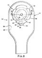
オストミーパウチ14のための多ペタル装着部材12が開示される(図1および図2)。多ペタル装着部材12は、(a)中心本体部分18、包囲周縁20、および外側周辺部22を備える柔軟なプラスチック部材16と、(b)第1の面26、反対側の第2の面28、および外側周辺部30を備える第1の両面接着剤基材24と、(c)第1の面34、反対側の第2の面36、および多ペタル外側周辺部38を備える第2の両面接着剤基材32と、(d)第1の面42、反対側の第2の面44、および多ペタル外側周辺部46を備える接着剤皮膚障壁部材40とを備える(図3および図4)。第1の両面接着剤基材24の外側周辺部30は、大きさおよび形が柔軟なプラスチック部材16の外側周辺部22に実質的に一致実質的に一致する。第1の両面接着剤基材24の第2の面28は、柔軟なプラスチック部材16の中心本体部分18および包囲周縁20に接着される。第2の両面接着剤基材32の多ペタル外側周辺部38は、柔軟なプラスチック部材16の外側周辺部22より大きい大きさを有すると共に、第2の両面接着剤基材32から径方向に延び、第2の両面接着剤基材32の周りに均等に分配され、第2の両面接着剤基材32から径方向に拡がる切り込み50によって分離された2〜8枚のペタル48に対応する形を有する。第2の両面接着剤基材32の第2の面36は、第1の両面接着剤基材24の第1の面26に接着される。接着剤皮膚障壁部材40の多ペタル外側周辺部46は、大きさおよび形が第2の両面接着剤基材32の多ペタル外側周辺部38に実質的に一致実質的に一致する。接着剤皮膚障壁部材40の第2の面44は、第2の両面接着剤基材32の第1の面34に接着される。
A multi-petal mounting
多ペタル装着部材12は、例えば、対応するオストミー器具52がオストメイトのストーマ周囲皮膚表面において滑らかなフィットでオストメイトに接着するように、および/または、オストミー器具52が、オストミー器具52もしくはオストメイトへの接着剤テープの適用を必要とすることなく、オストメイトのストーマ周囲皮膚表面においてオストメイトに接着するように、オストメイトのストーマ周囲領域において接着剤皮膚障壁部材40の向上したフィットを提供する。第2の両面接着剤基材32の多ペタル外側周辺部38の大きさおよび形を考慮し、また、接着剤皮膚障壁部材40の多ペタル外側周辺部46が、形および大きさにおいて第2の両面接着剤基材32の多ペタル外側周辺部38に実質的に一致実質的に一致するならば、接着剤皮膚障壁部材40の多ペタル外側周辺部46も、接着剤皮膚障壁部材40から径方向に延び、接着剤皮膚障壁部材40の周りに均等に分配され、接着剤皮膚障壁部材40から径方向に拡がる切り込み56によって分離された2〜8枚のペタル54に対応する形を有する。この構成は、多ペタル装着部材12を、適用時に望ましくないひだを生じることなく、オストメイトのストーマ周囲皮膚表面に適応させることができ、これは、平坦、湾曲、膨出、および/または不規則なストーマ周囲皮膚表面を伴うオストメイトといった、オストメイトのさまざまなストーマ周囲皮膚表面の輪郭にわたって当てはまる。パウチに体内排泄物が溜まっていくとき、接着剤皮膚障壁部材はしっかりと留まり、オストメイトのストーマ周囲皮膚表面に付着されたままとなり、剥離することはない。したがって、この構成は、向上したフィットを提供し、概してオストメイトについての向上した快適性を提供する。
The
柔軟なプラスチック部材16は、例えば、DuPontの製品ELVAX(R) 450といったエチレンおよび酢酸ビニルの共重合体から作ることができる。
The
第1の両面接着剤基材24は、例えば、発泡体層、熱可塑性プラスチック層、ポリプロピレン層、ポリエチレン層、不織布層、および/または膜層から作ることができる。また、第1の両面接着剤基材24は、柔らかい弾性の両面接着剤基材であり得る。したがって、一部の例では、第1の両面接着剤基材24は、例えば柔らかい弾性の発泡体層といった発泡体層を備えることができる。
The first double-sided
第2の両面接着剤基材32もまた、例えば、発泡体層、熱可塑性プラスチック層、ポリプロピレン層、ポリエチレン層、不織布層、および/または膜層から作ることができる。また、第2の両面接着剤基材32は、柔らかい弾性の両面接着剤基材であり得る。したがって、一部の例では、第2の両面接着剤基材32は、例えば柔らかい弾性の発泡体層といった発泡体層を備えることができる。
The second double-sided
接着剤皮膚障壁部材40は、皮膚障壁を提供するための適切な材料から作ることができ、しなりやすくすることができ、乾燥粘着性と湿り粘着性との両方を有することができる。
Adhesive
先に記載したように、第1の両面接着剤基材24の外側周辺部30は、大きさおよび形が柔軟なプラスチック部材16の外側周辺部22に実質的に一致実質的に一致している。例えば、第1の両面接着剤基材24の外側周辺部30は、第1の両面接着剤基材24がその位置合わせを最大化する向きで柔軟なプラスチック部材16に位置決めされるときに、第1の両面接着剤基材24の外側周辺部30が、第1の両面接着剤基材24の外側周辺部30に沿う任意の点において、柔軟なプラスチック部材16の外側周辺部22を越えて、例えばせいぜい10mm、3mm、または1mmだけ延びるように、大きさおよび形が柔軟なプラスチック部材16の外側周辺部22に対応できる。同じく、例えば、第1の両面接着剤基材24の外側周辺部30は、第1の両面接着剤基材24がその位置合わせを最大化する向きで柔軟なプラスチック部材16に位置決めされるときに、柔軟なプラスチック部材16の外側周辺部22が、柔軟なプラスチック部材16の外側周辺部22に沿う任意の点において、第1の両面接着剤基材24の外側周辺部30を越えて、例えばせいぜい10mm、3mm、または1mmだけ延びるように、大きさおよび形が柔軟なプラスチック部材16の外側周辺部22に対応できる。同じく、例えば、第1の両面接着剤基材24の外側周辺部30は、第1の両面接着剤基材24の外側周辺部30の大きさおよび形が柔軟なプラスチック部材16の外側周辺部22と同一となるように、大きさおよび形が柔軟なプラスチック部材16の外側周辺部22に対応できる。
As described above, the
第1の両面接着剤基材24の第2の面28は、柔軟なプラスチック部材16の中心本体部分18および包囲周縁20に接着される。接着は、例えば、第1の両面接着剤基材24の第2の面28に、ならびに/または、柔軟なプラスチック部材16の中心本体部分18および包囲周縁20に適用され、続いて、第1の両面接着剤基材24の第2の面28と柔軟なプラスチック部材の中心本体部分18および包囲周縁20とが接触して置かれる、例えば感圧接着剤層といった接着剤に基づき得る。
The
第2の両面接着剤基材32の多ペタル外側周辺部38は、柔軟なプラスチック部材16の外側周辺部22より大きい大きさを有すると共に、第2の両面接着剤基材32から径方向に延び、第2の両面接着剤基材32の周りに均等に分配され、第2の両面接着剤基材32から径方向に拡がる切り込み50によって分離された2〜8枚のペタル48に対応する形を有する(図3、図4、および図5)。
The multi-petal
大きさに関して、例えば、第2の両面接着剤基材32の多ペタル外側周辺部38は、第2の両面接着剤基材32が柔軟なプラスチック部材16にわたって位置決めされ、柔軟なプラスチック部材16に対して中心に置かれるときに、第2の両面接着剤基材32の多ペタル外側周辺部38が、第2の両面接着剤基材32の多ペタル外側周辺部38の少なくとも50%に沿って、柔軟なプラスチック部材16の外側周辺部22を越えて、例えば少なくとも5〜25mm、8〜20mm、または10〜15mmだけ延びるように、柔軟なプラスチック部材16の外側周辺部22より大きい大きさを有することができる(図4および図5)。同じく、例えば、第2の両面接着剤基材32の多ペタル外側周辺部38は、第2の両面接着剤基材32が柔軟なプラスチック部材16にわたって位置決めされ、柔軟なプラスチック部材16に対して中心に置かれるときに、第2の両面接着剤基材32の多ペタル外側周辺部38が、第2の両面接着剤基材32の多ペタル外側周辺部38の少なくとも95%、少なくとも98%、または100%に沿って、柔軟なプラスチック部材16の外側周辺部22を越えて、例えば少なくとも0.2〜25mm、0.5〜20mm、または1〜15mmだけ延びるように、柔軟なプラスチック部材16の外側周辺部22より大きい大きさを有することができる。
With respect to size, for example, the multi-petal
形に関して、例えば、第2の両面接着剤基材32の多ペタル外側周辺部38は、第2の両面接着剤基材32が中心を有し、2〜8枚のペタル48の各々が第2の両面接着剤基材32の中心に対して径方向に延びるように、第2の両面接着剤基材32から径方向に延び、第2の両面接着剤基材32の周りに均等に分配され、第2の両面接着剤基材32から径方向に拡がる切り込み50によって分離された2〜8枚のペタル48に対応する形を有することができる(図4、図5、および図6)。同じく、例えば、第2の両面接着剤基材32の多ペタル外側周辺部38は、2〜8枚のペタル48の各々が大きさにおいて実質的に同一になるように、および、2〜8枚のペタル48の各々が、隣接するペタル48から等距離に位置決めされるように、第2の両面接着剤基材32から径方向に延び、第2の両面接着剤基材32の周りに均等に分配され、第2の両面接着剤基材32から径方向に拡がる切り込み50によって分離された2〜8枚のペタル48に対応する形を有することができる。同じく、例えば、第2の両面接着剤基材32の多ペタル外側周辺部38は、2〜8枚のペタル48の各々が、切り込み50によってそのいずれの側方においても隣接するペタル48から分離され、各々の切り込み50が第2の両面接着剤基材32の中心に対する弓状の長さとして測定され、第2の両面接着剤基材32の中心から離れるにつれて大きくなる切り込み幅58を有するように、第2の両面接着剤基材32から径方向に延び、第2の両面接着剤基材32の周りに均等に分配され、第2の両面接着剤基材32から径方向に拡がる切り込み50によって分離された2〜8枚のペタル48に対応する形を有することができる。
In terms of shape, for example, the multi-petal
一部の例では、切り込み50は、例えば、柔軟なプラスチック部材16の外側周辺部22と第1の両面接着剤基材24の外側周辺部30とを径方向で越えた、0.5〜5mm、0.8〜3mm、または1〜2mmの距離といった、柔軟なプラスチック部材16の外側周辺部22と第1の両面接着剤基材24の外側周辺部30とを径方向で越えたある距離から始まって、第2の両面接着剤基材32から径方向に拡がる(図4、図5、および図6)。これらの例によれば、オストメイトに接着されるような多ペタル装着部材12の使用の間、この構成は、切り込み50から、柔軟なプラスチック部材16の外側周辺部22と第1の両面接着剤基材24の外側周辺部30とに径方向内向きに向かって延びる、第2の両面接着剤基材32における小さい裂け目の形成に基づいて、追加的な向上されたフィットを提供できる。
In some examples, the
第2の両面接着剤基材32の第2の面36は、第1の両面接着剤基材24の第1の面26に接着される。上記と同様に、接着は、例えば、第2の両面接着剤基材32の第2の面36に、および/または、第1の両面接着剤基材24の第1の面26に適用され、続いて、第2の両面接着剤基材32の第2の面36と第1の両面接着剤基材24の第1の面26とが接触して置かれる、例えば感圧接着剤層といった接着剤に基づき得る。
The
接着剤皮膚障壁部材40の多ペタル外側周辺部46は、大きさおよび形が第2の両面接着剤基材32の多ペタル外側周辺部38に実質的に一致実質的に一致する。上記と同様に、例えば、接着剤皮膚障壁部材40の多ペタル外側周辺部46は、接着剤皮膚障壁部材40がその位置合わせを最大化する向きで第2の両面接着剤基材32に位置決めされるときに、接着剤皮膚障壁部材40の多ペタル外側周辺部46が、接着剤皮膚障壁部材40の多ペタル外側周辺部46に沿う任意の位置において、第2の両面接着剤基材32の多ペタル外側周辺部38を越えて、例えばせいぜい10mm、3mm、または1mmだけ延びるように、大きさおよび形が第2の両面接着剤基材32の多ペタル外側周辺部38に対応できる。同じく、例えば、接着剤皮膚障壁部材40の多ペタル外側周辺部46は、接着剤皮膚障壁部材40がその位置合わせを最大化する向きで第2の両面接着剤基材32に位置決めされるときに、第2の両面接着剤基材32の多ペタル外側周辺部38が、第2の両面接着剤基材32の多ペタル外側周辺部38に沿う任意の位置において、接着剤皮膚障壁部材40の多ペタル外側周辺部46を越えて、例えばせいぜい10mm、3mm、または1mmだけ延びるように、大きさおよび形が第2の両面接着剤基材32の多ペタル外側周辺部38に対応できる。同じく、例えば、接着剤皮膚障壁部材40の多ペタル外側周辺部46は、接着剤皮膚障壁部材40の多ペタル外側周辺部46が大きさおよび形が第2の両面接着剤基材32の多ペタル外側周辺部38と同一となるように、大きさおよび形が第2の両面接着剤基材32の多ペタル外側周辺部38に対応できる。接着剤皮膚障壁部材40の多ペタル外側周辺部46は、接着剤皮膚障壁部材40から径方向に延び、接着剤皮膚障壁部材40の周りに均等に分配され、接着剤皮膚障壁部材40から径方向に拡がる切り込み56によって分離された2〜8枚のペタル54に対応する形も有する。
The multi-petal
接着剤皮膚障壁部材40の第2の面44は、第2の両面接着剤基材32の第1の面34に接着される。上記と同様に、接着は、例えば、接着剤皮膚障壁部材40の第2の面44に、および/または、第2の両面接着剤基材32の第1の面34に適用され、続いて、接着剤皮膚障壁部材40の第2の面44と第2の両面接着剤基材32の第1の面34とが接触して置かれる、例えば感圧接着剤層といった接着剤に基づき得る。
The
一部の例によれば、(i)柔軟なプラスチック部材16の中心本体部分18は第1の面60および反対側の第2の面62を有し、(ii)中心本体部分18の第1の面60は凸状であり、(iii)中心本体部分18の第2の面62は凹状であり、(iv)第1の両面接着剤基材24の第2の面28は、中心本体部分18の凸状の第1の面60において中心本体部分18に接着される(図3および図4)。例えば、中心本体部分18の第1の面60は、例えば2〜15mm、4〜12mm、5〜11mm、または6〜10mmの凸性を有することができる。同じく、例えば、中心本体部分18の第1の面60は、例えば、2mm、3mm、4mm、5mm、6mm、7mm、8mm、9mm、10mm、11mm、12mm、13mm、14mm、または15mmの凸性を有することができる。同じく、例えば、中心本体部分18の第2の面62は、例えば、2〜15mm、4〜12mm、5〜11mm、もしくは6〜10mm、または、2mm、3mm、4mm、5mm、6mm、7mm、8mm、9mm、10mm、11mm、12mm、13mm、14mm、もしくは15mmの凹性といった、中心本体部分18の第1の面60の凸性と相補の凹性を有することができる。これらの例によれば、中心本体部分18は、数ある形の中でも、例えば丸められた上部を伴う半球体といった球状キャップの形、または、平坦な上部を伴う半球体といった球状区域の形を有することができる。同じくこれらの例によれば、中心本体部分18の第1の面60が凸状であるという限りにおいて、多ペタル装着部材12の組み立て後には、第1の両面接着剤基材24の第1の面26、第2の両面接着剤基材32の第1の面34、および接着剤皮膚障壁部材40の第1の面42の対応する重なり合う部分も凸状となり、したがって、多ペタル装着部材12もその対応する部分において凸状となる。
According to some examples, (i) the
他の例によれば、(i)柔軟なプラスチック部材16の中心本体部分18は第1の面64および反対側の第2の面66を有し、(ii)中心本体部分18の第1の面64は平坦であり、(iii)中心本体部分18の第2の面66は平坦であり、(iv)第1の両面接着剤基材24の第2の面28は、中心本体部分18の平坦な第1の面64において中心本体部分18に接着される(図3および図5)。これらの例によれば、中心本体部分18の第1の面64が平坦であるという限りにおいて、第1の両面接着剤基材24の第1の面26、第2の両面接着剤基材32の第1の面34、および接着剤皮膚障壁部材40の第1の面42の対応する重なり合う部分も平坦であり、したがって、多ペタル装着部材12もその対応する部分において平坦である。
According to another example, (i) the
一部の例によれば、2〜8枚のペタル48は、第2の両面接着剤基材32から径方向外向きに初めに増加し次いで減少するペタル幅68を各々有する(図3、図4、および図6)。例えば、2〜8枚のペタル48は、第2の両面接着剤基材32が中心を有し、2〜8枚のペタル48が、第2の両面接着剤基材32の中心に対する弓状の長さとして測定され、第2の両面接着剤基材32の中心から離れるにつれて初めに増加し次いで減少するペタル幅68を各々有するように、第2の両面接着剤基材32から径方向外向きに、初めに増加し次いで減少するペタル幅68を各々有することができる。これらの例によれば、2〜8枚のペタル54もこの方法で寸法決定される。
According to some examples, the two to eight
同じく一部の例によれば、第2の両面接着剤基材32は最大半径70を有し、第2の両面接着剤基材32の多ペタル外側周辺部38の少なくとも50%は第2の両面接着剤基材32の最大半径70まで延びている(図3および図4)。例えば、第2の両面接着剤基材32は最大半径70を有することができ、第2の両面接着剤基材32の多ペタル外側周辺部38の少なくとも50%は、例えば、第2の両面接着剤基材32の多ペタル外側周辺部38の少なくとも50%、60%、70%、または80%が、第2の両面接着剤基材32の中心から同じ距離まで延び、第2の両面接着剤基材32の外側周辺部38における点がこれより遠くまで延びないように、第2の両面接着剤基材32の最大半径70まで延びることができる。これらの例によれば、接着剤皮膚障壁部材40もこの方法で寸法決定される。
Also according to some examples, the second double-sided
同じく一部の例によれば、第2の両面接着剤基材32の多ペタル外側周辺部38の形が3〜6枚のペタル48に対応する。例えば、第2の両面接着剤基材32の多ペタル外側周辺部38の形は、例えば、3枚のペタル48、4枚のペタル48、5枚のペタル48、または6枚のペタル48に対応できる。これらの例によれば、接着剤皮膚障壁部材40の多ペタル外側周辺部46の形もこの方法で寸法決定される。
Also according to some examples, the shape of the multi-petal
同じく一部の例によれば、柔軟なプラスチック部材16の包囲周縁20は実質的に環状である。例えば、柔軟なプラスチック部材16の包囲周縁20は円形とできる。別の例では、柔軟なプラスチック部材16の包囲周縁20は、例えば楕円形、多角形など、他の形を有することができる。
Also according to some examples, the surrounding
同じく一部の例によれば、柔軟なプラスチック部材16は装着輪72をさらに備え、装着輪72は、直径方向に反対と対向し、包囲周縁20から、第2の両面接着剤基材32の多ペタル外側周辺部38以内まで、および、接着剤皮膚障壁部材40の多ペタル外側周辺部46以内まで径方向外向きに延びている(図2、図3、および図4)。装着輪72は、例えば、多ペタル装着部材12をオストミーベルト(図示せず)に装着するために使用できる。
Also according to some examples, the
同じく一部の例によれば、接着剤皮膚障壁部材40はエラストマ親水コロイド混合物を含む。エラストマ親水コロイド混合物は、例えばカラヤ−グリセリンの配合処方、ポリアクリルアミド樹脂および/または他のポリオールの混合物を含むことができる。
Also according to some examples, the adhesive
同じく一部の例によれば、多ペタル装着部材12は、除去可能な保護膜74をさらに備え、除去可能な保護膜74は接着剤皮膚障壁部材40の第1の面42を覆う(図3および図4)。一部の例では、除去可能な保護膜74は、第2の両面接着剤基材32の多ペタル外側周辺部38と接着剤皮膚障壁部材40の多ペタル外側周辺部46とを越えて連続的に延び、除去可能な保護膜74を接着剤皮膚障壁部材40の第1の面42から除去するために使用できるタブなどの部品を含むことができる。
Also according to some examples, the
同じく一部の例によれば、柔軟なプラスチック部材16、第1の両面接着剤基材24、第2の両面接着剤基材32、および接着剤皮膚障壁部材40の各々は、中心に位置決めされてそれらを貫いて延びるストーマ入口門部76、78、80、82をそれぞれ有し、ストーマ入口門部76、78、80、82は、多ペタル装着部材12のストーマ入口門部84を一緒に形成する。柔軟なプラスチック部材16、第1の両面接着剤基材24、第2の両面接着剤基材32、および接着剤皮膚障壁部材40のストーマ入口門部76、78、80、82は、オストメイトのストーマに適した大きさおよび形をそれぞれ有することができる。例えば、ストーマ入口門部76、78、80、82は、例として約12〜13mm、約15〜16mm、約22〜23mm、約25〜26mm、約28〜29mm、約31〜32mm、約34〜35mm、約38〜39mm、約41〜42mm、または約44〜45mmといった、例えば10mm〜50mmの直径に対応する大きさを有することができる。同じく、例えば、ストーマ入口門部76、78、80、82は、例えば12.7mm、15.9mm、22.2mm、25.4mm、28.6mm、31.8mm、34.9mm、41.3mm、または44.5mmといった直径に対応する大きさを有することができる。同じく、例えば、ストーマ入口門部76、78、80、82は、円形に対応する形を有することができる。同じく、例えば、ストーマ入口門部76、78、80、82は、オストメイトのストーマにフィットするように切断される形を有することができる。
Also according to some examples, each of the
多ペタル装着部材12は、次のように組み立てられ得る。感圧接着剤層が、第1の両面接着剤基材24の第1の面26、第1の両面接着剤基材24の第2の面28、および第2の両面接着剤基材32の第1の面34の各々に適用される。組み立ての間の取り扱いの容易性のために、感圧接着剤層は保護ライナによってそれぞれ覆われる。保護ライナは、第1の両面接着剤基材24の第1の面26の感圧接着剤層から除去される。第1の両面接着剤基材24は、第2の両面接着剤基材32に対して中心に置かれる。第1の両面接着剤基材24の第1の面26の感圧接着剤層は、第2の両面接着剤基材32の第2の面36に接着される。組み立てを支援するために、パイロット開口部が第1の両面接着剤基材24の中心と第2の両面接着剤基材32の中心とに設けられてもよい。第1の両面接着剤基材24と第2の両面接着剤基材32とが組み立てられた後、保護ライナが第2の両面接着剤基材32の第1の面34の感圧接着剤層から除去される。第2の両面接着剤基材32は、接着剤皮膚障壁部材40に対して中心に置かれる。第2の両面接着剤基材32の第1の面34の感圧接着剤層は、接着剤皮膚障壁部材40の第2の面44に接着される。組み立てを支援するために、パイロット開口部が接着剤皮膚障壁部材40の中心に設けられてもよい。第1の両面接着剤基材24と、第2の両面接着剤基材32と、接着剤皮膚障壁部材40とが組み立てられた後、保護ライナが第1の両面接着剤基材24の第2の面28の感圧接着剤層から除去される。第1の両面接着剤基材24は、柔軟なプラスチック部材16に対して中心に置かれる。第1の両面接着剤基材24の第2の面28の感圧接着剤層は、中心本体部分18および包囲周縁20を含む柔軟なプラスチック部材16の面に接着される。組み立てを支援するために、パイロット開口部が柔軟なプラスチック部材16の中心に設けられてもよい。柔軟なプラスチック部材16の包囲周縁20、ならびに/または、柔軟なプラスチック部材16の包囲周縁20に重なる第1の両面接着剤基材24、第2の両面接着剤基材32、および接着剤皮膚障壁部材40の部分を含む、形成された組立体の環状領域z(図3)に、熱および圧力が適用される。多ペタル装着部材12は、他の方法によって組み立てられてもよい。
The
オストミー器具52も開示される(図2)。オストミー器具52は多ペタル装着部材12を備える。オストミー器具52はオストミーパウチ14も備える。
多ペタル装着部材12は先に記載されているとおりである。したがって、多ペタル装着部材12は、(a)中心本体部分18、包囲周縁20、および外側周辺部22を備える柔軟なプラスチック部材16と、(b)第1の面26、反対側の第2の面28、および外側周辺部30を備える第1の両面接着剤基材24と、(c)第1の面34、反対側の第2の面36、および多ペタル外側周辺部38を備える第2の両面接着剤基材32と、(d)第1の面42、反対側の第2の面44、および多ペタル外側周辺部46を備える接着剤皮膚障壁部材40とを備える(図3および図4)。第1の両面接着剤基材24の外側周辺部30は、大きさおよび形が柔軟なプラスチック部材16の外側周辺部22に実質的に一致する。第1の両面接着剤基材24の第2の面28は、柔軟なプラスチック部材16の中心本体部分18および包囲周縁20に接着される。第2の両面接着剤基材32の多ペタル外側周辺部38は、柔軟なプラスチック部材16の外側周辺部22より大きい大きさを有すると共に、第2の両面接着剤基材32から径方向に延び、第2の両面接着剤基材32の周りに均等に分配され、第2の両面接着剤基材32から径方向に拡がる切り込み50によって分離された2〜8枚のペタル48に対応する形を有する。第2の両面接着剤基材32の第2の面36は、第1の両面接着剤基材24の第1の面26に接着される。接着剤皮膚障壁部材40の多ペタル外側周辺部46は、大きさおよび形が第2の両面接着剤基材32の多ペタル外側周辺部38に実質的に一致する。接着剤皮膚障壁部材40の第2の面44は、第2の両面接着剤基材32の第1の面34に接着される。
The
オストミーパウチ14は、プラスチック膜の近位シート86とプラスチック膜の遠位シート88とを備え、近位シート86と遠位シート88とは、オストミーパウチ14を形成するためのそれらのそれぞれの周囲において封止される(図2および図3)。近位シート86は、内側周辺部92と、内側周辺部を包囲する領域94とを有するストーマ入口門部90を備える。柔軟なプラスチック部材16の包囲周縁20は内側周辺部96をさらに備える。柔軟なプラスチック部材16の包囲周縁20の内側周辺部96は、大きさおよび形が近位シート86のストーマ入口門部90の内側周辺部92に実質的に一致する。柔軟なプラスチック部材16の包囲周縁20は、近位シート86のストーマ入口門部90の内側周辺部92を包囲する領域に封止される。
The
オストミーパウチは、例えばオストミーパウチの内容物を流し出すための開口を有さないことで1回の使用のために、または、例えばオストミーパウチの内容物を流し出すための開口を有することで複数回の使用のために、設計されてもよい。 The ostomy pouch may be used, for example, by not having an opening for flushing the contents of the ostomy pouch, or for multiple times, for example having an aperture for flushing the contents of the ostomy pouch. May be designed for use.
オストミー器具52は次のように作ることができる。多ペタル装着部材12は、オストミーパウチ14の近位シート86になるプラスチック膜のシートに置かれる。多ペタル装着部材12は、近位シート86のストーマ入口門部90にわたって置かれる。近位シート86は、オストメイトの快適性のための布状の多孔質材料で覆われてもよい。柔軟なプラスチック部材16、第1の両面接着剤基材24、第2の両面接着剤基材32、および接着剤皮膚障壁部材40の各々の中心に設けられたパイロット開口部は、適切な大きさとされたストーマ入口門部76、78、80、82を各々においてそれぞれ形成するために型打ちされる。柔軟なプラスチック部材16の包囲周縁20、ならびに/または、柔軟なプラスチック部材16の包囲周縁20に重なることで柔軟なプラスチック部材16の包囲周縁20を近位シート86に封止する第1の両面接着剤基材24、第2の両面接着剤基材32、および接着剤皮膚障壁部材40の部分を含む、形成された組立体の環状領域z(図3)に、熱および圧力が適用される。近位シート86は、オストミーパウチ14の遠位シート88になるプラスチック膜の別のシートで裏打ちされる。次に、近位シート86および遠位シート88を線に沿って型打ちし、続いて線に沿って熱封止することで、オストミーパウチ14が形成される。
The
同じく開示されるのは、オストメイトのストーマ周囲皮膚表面においてオストミー器具をオストメイトに接着する方法である(図2)。方法によれば、オストミー器具52は多ペタル装着部材12を備える。オストミー器具52はオストミーパウチ14も備える。
Also disclosed is a method of adhering an ostomy device to an ostomate at the peristomal skin surface of the ostomate (FIG. 2). According to the method, the
多ペタル装着部材12は先に記載されているとおりである。したがって、多ペタル装着部材12は、(a)中心本体部分18、包囲周縁20、および外側周辺部22を備える柔軟なプラスチック部材16と、(b)第1の面26、反対側の第2の面28、および外側周辺部30を備える第1の両面接着剤基材24と、(c)第1の面34、反対側の第2の面36、および多ペタル外側周辺部38を備える第2の両面接着剤基材32と、(d)第1の面42、反対側の第2の面44、および多ペタル外側周辺部46を備える接着剤皮膚障壁部材40とを備える(図3および図4)。第1の両面接着剤基材24の外側周辺部30は、大きさおよび形が柔軟なプラスチック部材16の外側周辺部22に実質的に一致実質的に一致する。第1の両面接着剤基材24の第2の面28は、柔軟なプラスチック部材16の中心本体部分18および包囲周縁20に接着される。第2の両面接着剤基材32の多ペタル外側周辺部38は、柔軟なプラスチック部材16の外側周辺部22より大きい大きさを有すると共に、第2の両面接着剤基材32から径方向に延び、第2の両面接着剤基材32の周りに均等に分配され、第2の両面接着剤基材32から径方向に拡がる切り込み50によって分離された2〜8枚のペタル48に対応する形を有する。第2の両面接着剤基材32の第2の面36は、第1の両面接着剤基材24の第1の面26に接着される。接着剤皮膚障壁部材40の多ペタル外側周辺部46は、大きさおよび形が第2の両面接着剤基材32の多ペタル外側周辺部38に実質的に一致する。接着剤皮膚障壁部材40の第2の面44は、第2の両面接着剤基材32の第1の面34に接着される。
The
多ペタル装着部材12は、除去可能な保護膜74をさらに備え、除去可能な保護膜74は接着剤皮膚障壁部材40の第1の面42を覆う。ここでも、一部の例では、除去可能な保護膜74は、第2の両面接着剤基材32の多ペタル外側周辺部38と接着剤皮膚障壁部材40の多ペタル外側周辺部46とを越えて連続的に延び、除去可能な保護膜74を接着剤皮膚障壁部材40の第1の面42から除去するために使用できるタブなどの部品を含むことができる。
The
柔軟なプラスチック部材16、第1の両面接着剤基材24、第2の両面接着剤基材32、および接着剤皮膚障壁部材40の各々は、中心に位置決めされてそれらを貫いて延びるストーマ入口門部76、78、80、82をそれぞれ有する。
Each of the
オストミーパウチ14は、プラスチック膜の近位シート86とプラスチック膜の遠位シート88とを備え、近位シート86と遠位シート88とは、オストミーパウチ14を形成するためのそれらのそれぞれの周囲において封止される(図2および図3)。近位シート86は、内側周辺部92と、内側周辺部を包囲する領域94とを有するストーマ入口門部90を備える。柔軟なプラスチック部材16の包囲周縁20は内側周辺部96をさらに備える。柔軟なプラスチック部材16の包囲周縁20の内側周辺部96は、大きさおよび形が近位シート86のストーマ入口門部90の内側周辺部92に実質的に一致する。柔軟なプラスチック部材16の包囲周縁20は、近位シート86のストーマ入口門部90の内側周辺部92を包囲する領域に封止される。
The
方法は、(1)接着剤皮膚障壁部材40の第1の面42から除去可能な保護膜74を除去するステップを含む(図4)。これは、接着剤皮膚障壁部材40の第1の面42を露出させる。
The method includes (1) removing the removable
方法は、(2)オストミーパウチ14の近位シート86のストーマ入口門部90と、柔軟なプラスチック部材16、第1の両面接着剤基材24、第2の両面接着剤基材32、および接着剤皮膚障壁部材40のストーマ入口門部76、78、80、82とがオストメイトのストーマとそれぞれ位置合わせされるように、オストメイトのストーマ周囲領域において接着剤皮膚障壁部材40の第1の面42を置くステップも含む。方法によれば、それによってオストミー器具52はオストメイトのストーマ周囲皮膚表面においてオストメイトに接着される(図2、図3、および図4)。
The method includes (2) stoma inlet portal 90 of
一部の例によれば、オストミー器具52は、オストメイトのストーマ周囲皮膚表面において滑らかなフィットでオストメイトに接着する。例えば、オストミー器具52は、適用時に望ましくないひだを生じることなく、多ペタル装着部材12がオストメイトのストーマ周囲皮膚表面に適応されるように、オストメイトのストーマ周囲皮膚表面に滑らかなフィットでオストメイトに接着できる。同じく、例えば、オストミー器具52は、平坦、湾曲、膨出、および/または不規則であるストーマ周囲皮膚表面を伴うオストメイトといった、オストメイトのさまざまなストーマ周囲皮膚表面の輪郭にわたって、オストメイトのストーマ周囲皮膚表面に滑らかなフィットでオストメイトに接着できる。パウチに体内排泄物が溜まっていくとき、接着剤皮膚障壁部材40はしっかりと留まり、オストメイトのストーマ周囲皮膚表面に付着されたままとなり、剥離することはない。
According to some examples, the
同じく一部の例によれば、オストミー器具52は、オストミー器具52またはオストメイトに接着剤テープを適用することなく、オストメイトのストーマ周囲皮膚表面においてオストメイトに接着する。例えば、オストミー器具52は、接着剤テープがオストメイトのストーマ周囲皮膚表面における皮膚、およびストーマ周囲皮膚表面に隣接した皮膚に対して装着部材を滑らかにする、押し付ける、または接着するために適用される必要がないように、オストミー器具52またはオストメイトに接着剤テープを適用することなく、オストメイトのストーマ周囲皮膚表面においてオストメイトに接着できる。同じく、例えば、オストミー器具52は、平坦、湾曲、膨出、および/または不規則であるストーマ周囲皮膚表面を伴うオストメイトといった、オストメイトのさまざまなストーマ周囲皮膚表面の輪郭にわたって、オストミー器具52またはオストメイトに接着剤テープを適用することなく、オストメイトのストーマ周囲皮膚表面においてオストメイトに接着できる。ここでも、パウチに体内排泄物が溜まっていくとき、接着剤皮膚障壁部材40はしっかりと留まり、オストメイトのストーマ周囲皮膚表面に付着されたままとなり、剥離することはない。
Also according to some examples,
一部の例によれば、(i)柔軟なプラスチック部材16の中心本体部分18は第1の面60および反対側の第2の面62を有し、(ii)中心本体部分18の第1の面60は凸状であり、(iii)中心本体部分18の第2の面62は凹状であり、(iv)第1の両面接着剤基材24の第2の面28は、中心本体部分18の凸状の第1の面60において中心本体部分18に接着される。
According to some examples, (i) the
ここでも一部の例によれば、(i)柔軟なプラスチック部材16の中心本体部分18は第1の面64および反対側の第2の面66を有し、(ii)中心本体部分18の第1の面64は平坦であり、(iii)中心本体部分18の第2の面66は平坦であり、(iv)第1の両面接着剤基材24の第2の面28は、中心本体部分18の平坦な第1の面64において中心本体部分18に接着される。
Again, according to some examples, (i) the
同じく一部の例によれば、2〜8枚のペタル48は、第2の両面接着剤基材32から径方向外向きに初めに増加し次いで減少するペタル幅68を各々有する。
Also according to some examples, the two to eight
同じく一部の例によれば、第2の両面接着剤基材32は最大半径70を有し、第2の両面接着剤基材32の多ペタル外側周辺部38の少なくとも50%は第2の両面接着剤基材32の最大半径70まで延びる。
Also according to some examples, the second double-sided
同じく一部の例によれば、第2の両面接着剤基材32の多ペタル外側周辺部38の形が3〜6枚のペタル48に対応する。
Also according to some examples, the shape of the multi-petal
同じく一部の例によれば、柔軟なプラスチック部材16の包囲周縁20は実質的に環状である。
Also according to some examples, the surrounding
同じく一部の例によれば、柔軟なプラスチック部材16は装着輪72をさらに備え、装着輪72は、直径方向に互いと対向し、包囲周縁20から、第2の両面接着剤基材32の多ペタル外側周辺部38以内まで、および、接着剤皮膚障壁部材40の多ペタル外側周辺部46以内まで径方向外向きに延びている。
Also according to some examples, the
同じく一部の例によれば、接着剤皮膚障壁部材40はエラストマ親水コロイド混合物を含む。
Also according to some examples, the adhesive
同じく開示されるのは、オストメイトのストーマ周囲皮膚表面においてオストミー器具52をオストメイトに接着する別の方法である(図2)。方法によれば、オストミー器具52は多ペタル装着部材12を備える。オストミー器具52はオストミーパウチ14も備える。
Also disclosed is another method of adhering
多ペタル装着部材12は先に記載されているとおりである。したがって、多ペタル装着部材12は、(a)中心本体部分18、包囲周縁20、および外側周辺部22を備える柔軟なプラスチック部材16と、(b)第1の面26、反対側の第2の面28、および外側周辺部30を備える第1の両面接着剤基材24と、(c)第1の面34、反対側の第2の面36、および多ペタル外側周辺部38を備える第2の両面接着剤基材32と、(d)第1の面42、反対側の第2の面44、および多ペタル外側周辺部46を備える接着剤皮膚障壁部材40とを備える(図3および図4)。第1の両面接着剤基材24の外側周辺部30は、大きさおよび形が柔軟なプラスチック部材16の外側周辺部22に実質的に一致する。第1の両面接着剤基材24の第2の面28は、柔軟なプラスチック部材16の中心本体部分18および包囲周縁20に接着される。第2の両面接着剤基材32の多ペタル外側周辺部38は、柔軟なプラスチック部材16の外側周辺部22より大きい大きさを有すると共に、第2の両面接着剤基材32から径方向に延び、第2の両面接着剤基材32の周りに均等に分配され、第2の両面接着剤基材32から径方向に拡がる切り込み50によって分離された2〜8枚のペタル48に対応する形を有する。第2の両面接着剤基材32の第2の面36は、第1の両面接着剤基材24の第1の面26に接着される。接着剤皮膚障壁部材40の多ペタル外側周辺部46は、大きさおよび形が第2の両面接着剤基材32の多ペタル外側周辺部38に実質的に一致する。接着剤皮膚障壁部材40の第2の面44は、第2の両面接着剤基材32の第1の面34に接着される。
The
多ペタル装着部材12は、除去可能な保護膜74をさらに備え、除去可能な保護膜74は接着剤皮膚障壁部材40の第1の面42を覆う。ここでも、一部の例では、除去可能な保護膜74は、第2の両面接着剤基材32の多ペタル外側周辺部38と接着剤皮膚障壁部材40の多ペタル外側周辺部46とを越えて連続的に延び、除去可能な保護膜74を接着剤皮膚障壁部材40の第1の面42から除去するために使用できるタブなどの部品を含むことができる。
The
オストミーパウチ14は、プラスチック膜の近位シート86とプラスチック膜の遠位シート88とを備え、近位シート86と遠位シート88とは、オストミーパウチ14を形成するためのそれらのそれぞれの周囲において封止される(図2および図3)。近位シート86は、内側周辺部92と、内側周辺部を包囲する領域94とを有するストーマ入口門部90を備える。柔軟なプラスチック部材16の包囲周縁20は内側周辺部96をさらに備える。柔軟なプラスチック部材16の包囲周縁20の内側周辺部96は、大きさおよび形が近位シート86のストーマ入口門部90の内側周辺部92に実質的に一致する。柔軟なプラスチック部材16の包囲周縁20は、近位シート86のストーマ入口門部90の内側周辺部92を包囲する領域に封止される。
The
方法は、(1)接着剤皮膚障壁部材40の第1の面42から除去可能な保護膜74を除去するステップを含む(図4)。方法は、(2)柔軟なプラスチック部材16、第1の両面接着剤基材24、第2の両面接着剤基材32、および接着剤皮膚障壁部材40の各々が、それぞれ中心に位置決めされてそれらを貫いて延びるストーマ入口門部76、78、80、82を有するように、少なくとも接着剤皮膚障壁部材40を貫いて中心に位置決めされる孔を切断するステップも含む(図2、図3、および図4)。方法は、(3)オストミーパウチ14の近位シート86のストーマ入口門部90と、柔軟なプラスチック部材16、第1の両面接着剤基材24、第2の両面接着剤基材32、および接着剤皮膚障壁部材40のストーマ入口門部76、78、80、82とがオストメイトのストーマとそれぞれ位置合わせされるように、オストメイトのストーマ周囲領域において接着剤皮膚障壁部材40の第1の面42を置くステップも含む。方法によれば、それによってオストミー器具52はオストメイトのストーマ周囲皮膚表面においてオストメイトに接着される。
The method includes (1) removing the removable
一部の例では、オストミー器具52は、オストメイトのストーマ周囲皮膚表面において滑らかなフィットでオストメイトに接着する。
In some cases, the
同じく一部の例では、オストミー器具52は、オストミー器具52またはオストメイトに接着剤テープを適用することなく、オストメイトのストーマ周囲皮膚表面においてオストメイトに接着する。
Also in some examples,
一部の例によれば、(i)柔軟なプラスチック部材16の中心本体部分18は第1の面60および反対側の第2の面62を有し、(ii)中心本体部分18の第1の面60は凸状であり、(iii)中心本体部分18の第2の面62は凹状であり、(iv)第1の両面接着剤基材24の第2の面28は、中心本体部分18の凸状の第1の面60において中心本体部分18に接着される。
According to some examples, (i) the
同じく一部の例によれば、(i)柔軟なプラスチック部材16の中心本体部分18は第1の面64および反対側の第2の面66を有し、(ii)中心本体部分18の第1の面64は平坦であり、(iii)中心本体部分18の第2の面66は平坦であり、(iv)第1の両面接着剤基材24の第2の面28は、中心本体部分18の平坦な第1の面64において中心本体部分18に接着される。
Also according to some examples, (i) the
同じく一部の例によれば、2〜8枚のペタル48は、第2の両面接着剤基材32から径方向外向きに初めに増加し次いで減少するペタル幅68を各々有する。
Also according to some examples, the two to eight
同じく一部の例によれば、第2の両面接着剤基材32は最大半径70を有し、第2の両面接着剤基材32の多ペタル外側周辺部38の少なくとも50%は第2の両面接着剤基材32の最大半径70まで延びる。
Also according to some examples, the second double-sided
同じく一部の例によれば、第2の両面接着剤基材32の多ペタル外側周辺部38の形が3〜6枚のペタル48に対応する。
Also according to some examples, the shape of the multi-petal
同じく一部の例によれば、柔軟なプラスチック部材16の包囲周縁20は実質的に環状である。
Also according to some examples, the surrounding
同じく一部の例によれば、柔軟なプラスチック部材16は装着輪72をさらに備え、装着輪72は、直径方向に互いと対向し、包囲周縁20から、第2の両面接着剤基材32の多ペタル外側周辺部38以内まで、および、接着剤皮膚障壁部材40の多ペタル外側周辺部46以内まで径方向外向きに延びている。
Also according to some examples, the
同じく一部の例によれば、接着剤皮膚障壁部材40はエラストマ親水コロイド混合物を含む。
Also according to some examples, the adhesive
オストミーパウチのための多ペタル装着部材と、オストミーパウチのための円形(つまり、多ペタルでない)装着部材とによる表面接着の比較を行った。比較は次のステップを伴った。最初に、各々の装着部材の大部分が湾曲した表面に手によって押し付けられるように、多ペタル装着部材と円形の装着部材とが物体の湾曲した表面に適用された。次に、各々の装着部材の適用が滑らかなフィットで達成されたかどうか、または、望ましくないひだが生じていないかどうかが観察された。そのとき、物体はおおよそ24℃においておおよそ24時間にわたって維持された。最後に、物体の湾曲した表面からの装着部材のいずれかの剥離が、各々の装着部材が湾曲した表面に手によって押し付けられた場所で起こっているかどうかが観察された。 A surface adhesion comparison was made between a multi-petal mounting member for the ostomy pouch and a circular (ie, non-petal) mounting member for the ostomy pouch. The comparison involved the following steps. First, a multi-petal mounting member and a circular mounting member were applied to the curved surface of the object so that the majority of each mounting member was manually pressed against the curved surface. It was then observed whether the application of each mounting member was achieved with a smooth fit, or if there were unwanted pleats. The body was then maintained at approximately 24° C. for approximately 24 hours. Finally, it was observed whether any detachment of the mounting members from the curved surface of the object occurred where each mounting member was manually pressed onto the curved surface.
2つの物体、すなわち、ボールと花瓶とが使用された。ボールは、丸い表面に対応する湾曲した表面を有する。花瓶は、凸状の表面に対応する湾曲した表面を有する。湾曲した表面は、例えば太り過ぎのオストメイトを連想させる湾曲した腹部表面、および、同じく例えば腰が曲がっているオストメイトを連想させる湾曲した腹部表面などのオストメイトのストーマ周囲皮膚表面と類似している。多ペタル装着部材と円形の装着部材とは両方で、オストミー器具の装着部材において商業的に使用されるエラストマ親水コロイド混合物に対応する同じ接着剤を含んでいる。接着剤は皮膚に特異的ではなく、ボールおよび花瓶に対して、皮膚の場合と同様に接着を達成すると考えられる。 Two objects were used, a ball and a vase. The ball has a curved surface that corresponds to a rounded surface. The vase has a curved surface that corresponds to the convex surface. A curved surface is similar to a peristomal skin surface of an ostomate, such as a curved abdominal surface reminiscent of overweight ostomate, and a curved abdominal surface also reminiscent of, for example, a bent ostomate. Both the multi-petal mounting member and the circular mounting member contain the same adhesive corresponding to the elastomeric hydrocolloid mixture used commercially in ostomy appliance mounting members. The adhesive is not skin-specific and is believed to achieve adhesion to balls and vases as it does to skin.
これらの比較のために、多ペタル装着部材および円形の装着部材による表面接着は、オストミーパウチを装着部材に付着させることなく試験された。これは、比較がボールおよび花瓶の湾曲した表面への装着部材の接着に着目しており、装着部材にオストミーパウチを付着させると、湾曲した表面に接着されるために装着部材が見えにくくなるためである。 For these comparisons, surface adhesion with multiple petal mounts and circular mounts was tested without attaching the ostomy pouch to the mount. This is because the comparison focuses on the adhesion of the mounting member to the curved surface of the ball and vase, and when the ostomy pouch is attached to the mounting member, the mounting member becomes difficult to see because it adheres to the curved surface. Is.
4つの比較の結果が図7、図8、図9、および図10に示されている。 The results of the four comparisons are shown in FIGS. 7, 8, 9 and 10.
第1の比較では、各々の装着部材の大部分が手によって湾曲した表面に押し付けられるように多ペタル装着部材および円形の装着部材をボールの湾曲した表面へと適用することに続いて、多ペタル装着部材の適用が滑らかなフィットで達成されており(図7A、左側、上半分)、一方、円形の装着部材の適用時には望ましくないひだが生じている(図7A、右側、上半分)ことが観察された。また、ボールがおおよそ24℃においておおよそ24時間にわたって維持された後、ボールからの多ペタル装着部材の剥離は、多ペタル装着部材が手によって湾曲した表面に押し付けられた場所で起こらず(図7B、右側、上半分)、一方、ボールからの円形の装着部材の剥離が、円形の装着部材が手によって湾曲した表面に押し付けられた場所で起こった(図7B、左側、上半分)ことが観察された。 In a first comparison, applying a multi-petal mounting member and a circular mounting member to a curved surface of a ball such that the majority of each mounting member is pressed by hand onto the curved surface, followed by multi-petal mounting. The application of the mounting member has been achieved with a smooth fit (FIG. 7A, left side, upper half), while undesired folds have occurred when applying a circular mounting member (FIG. 7A, right side, upper half). Was observed. Also, after the ball has been maintained at approximately 24° C. for approximately 24 hours, detachment of the multi-petal mounting member from the ball does not occur where the multi-petal mounting member is manually pressed against the curved surface (FIG. 7B, It was observed that delamination of the circular mounting member from the ball occurred where the circular mounting member was manually pressed against the curved surface (Fig. 7B, left side, upper half), while the right side, upper half). It was
同様に、第2の比較では、各々の装着部材の大部分が手によって湾曲した表面に押し付けられるように多ペタル装着部材および円形の装着部材を花瓶の湾曲した表面へと適用することに続いて、多ペタル装着部材の適用が滑らかなフィットで達成されており(図8A、左側、上半分)、一方、円形の装着部材の適用時には望ましくないひだが生じている(図8A、右側、上半分)ことが観察された。また、花瓶がおおよそ24℃においておおよそ24時間にわたって維持された後、花瓶からの多ペタル装着部材の剥離が、多ペタル装着部材が手によって湾曲した表面に押し付けられた場所で起こらず(図8B、左側、上半分)、一方、花瓶からの円形の装着部材の剥離が、円形の装着部材が手によって湾曲した表面に押し付けられた場所で起こった(図8B、右側、上半分)ことが観察された。 Similarly, in a second comparison, following application of a multipetal mounting member and a circular mounting member to the curved surface of the vase so that the majority of each mounting member is pressed by hand onto the curved surface. , The application of a multi-petal mounting member has been achieved with a smooth fit (Fig. 8A, left side, upper half), while an undesired crease occurs when applying a circular mounting member (Fig. 8A, right side, upper half). ) Was observed. Also, after the vase was maintained at approximately 24° C. for approximately 24 hours, peeling of the multi-petal mounting member from the vase did not occur where the multi-petal mounting member was pressed against the curved surface by hand (FIG. 8B, It was observed that delamination of the circular mounting member from the vase occurred where the circular mounting member was pressed against the curved surface by hand (FIG. 8B, right half, upper half), while the left mounting, upper half). It was
第1の比較と同様に、第3の比較では、各々の装着部材の大部分が手によって湾曲した表面に押し付けられるように多ペタル装着部材および円形の装着部材をボールの湾曲した表面へと適用することに続いて、多ペタル装着部材の適用が滑らかなフィットで達成されており(図9A、右側、上半分)、一方、円形の装着部材の適用時には望ましくないひだが生じている(図9A、左側、上半分)ことが観察された。また、ボールがおおよそ24℃においておおよそ24時間にわたって維持された後、ボールからの多ペタル装着部材の剥離が、多ペタル装着部材が手によって湾曲した表面に押し付けられた場所で起こらず(図9B、右側、下半分)、一方、ボールからの円形の装着部材の剥離が、円形の装着部材が手によって湾曲した表面に押し付けられた場所で起こった(図9B、左側、上半分)ことが観察された。 Similar to the first comparison, in the third comparison, a multi-petal mounting member and a circular mounting member were applied to the curved surface of the ball so that the majority of each mounting member was pressed by hand onto the curved surface. Following that, the application of multiple petal mounting members has been achieved with a smooth fit (Fig. 9A, right side, upper half), while undesired pleats have been created when applying circular mounting members (Fig. 9A). , Left side, upper half). Also, after the ball has been maintained at approximately 24° C. for approximately 24 hours, separation of the multi-petal mounting member from the ball does not occur where the multi-petal mounting member is manually pressed against the curved surface (FIG. 9B, It was observed that the detachment of the circular mounting member from the ball occurred where the circular mounting member was pressed against the curved surface by hand (Fig. 9B, left side, upper half), while the right side, lower half). It was
また、第2の比較と同様に、第4の比較では、各々の装着部材の大部分が手によって湾曲した表面に押し付けられるように多ペタル装着部材および円形の装着部材を花瓶の湾曲した表面へと適用することに続いて、多ペタル装着部材の適用が滑らかなフィットで達成されており(図10A、左側、上半分)、一方、円形の装着部材の適用時には望ましくないひだが生じている(図10A、右側、上半分)ことが観察された。また、花瓶がおおよそ24℃においておおよそ24時間にわたって維持された後、花瓶からの多ペタル装着部材の剥離が、多ペタル装着部材が手によって湾曲した表面に押し付けられた場所で起こらず(図10B、左側、上半分)、一方、花瓶からの円形の装着部材の剥離が、円形の装着部材が手によって湾曲した表面に押し付けられた場所で起こった(図10B、右側、上半分)ことが観察された。 Also, similar to the second comparison, in the fourth comparison, the multi-petal mounting member and the circular mounting member are attached to the curved surface of the vase so that the majority of each mounting member is pressed by hand onto the curved surface. Following the application, the application of a multi-petal mounting member has been achieved with a smooth fit (FIG. 10A, left side, upper half), while undesired pleats have been created when a circular mounting member is applied ( FIG. 10A, right side, upper half) was observed. Also, after the vase was maintained at approximately 24° C. for approximately 24 hours, peeling of the multi-petal mounting member from the vase did not occur where the multi-petal mounting member was pressed against the curved surface by hand (FIG. 10B, It was observed that delamination of the circular mounting member from the vase occurred where the circular mounting member was pressed by hand against the curved surface (FIG. 10B, right half, upper half), while the left mounting, upper half). It was
結果は、オストミーパウチのための多ペタル装着部材が、多ペタル装着部材を備えたオストミー器具が同じことを行うことと一致して、適用時に望ましくないひだが生じることなく、さまざまな表面輪郭にわたって、オストメイトのストーマ周囲皮膚表面に類似する湾曲した表面に滑らかなフィットで接着できることを実証している。結果は、オストミーパウチのための多ペタル装着部材が、同じく多ペタル装着部材を備えたオストミー器具が同じことを行うことと一致して、表面に対して、さまざまな表面輪郭にわたって、装着部材を滑らかにする、押し付ける、または接着するために接着剤テープが適用される必要がないように、多ペタル装着部材または湾曲した表面への接着剤テープの適用なしで、オストメイトのストーマ周囲皮膚表面と類似の湾曲した表面に接着できることも実証している。これらの結果に基づいて、多ペタル装着部材は、特には対応するオストミーパウチが体内排泄物で満たされ、そのためオストミーパウチの重量が増加したとき、例えば、数時間から半日までの着用時間に対して3〜5日間の着用時間といった、円形の装着部材に対してより長い着用時間を提供できると考えられる。 The result is that a multi-petal mounting member for an ostomy pouch is consistent with that an ostomy appliance with a multi-petal mounting member does the same, over various surface contours without unwanted folds during application. It demonstrates that it can adhere with a smooth fit to curved surfaces resembling ostomate's peristomal skin surface. The results are consistent with the fact that a multi-petal mounting member for an ostomy pouch does the same for an ostomy appliance that also has a multi-petal mounting member, smoothing the mounting member over various surface contours with respect to the surface. Similar to the ostomate's peristomal skin surface without the application of adhesive tape to a multi-petal attachment or curved surface so that adhesive tape does not need to be applied to make, press or glue. It has also demonstrated that it can adhere to curved surfaces. Based on these results, the multi-petal mounting member is particularly suitable for wearing times of several hours up to half a day, especially when the corresponding ostomy pouch is filled with body exudates and thus the weight of the ostomy pouch increases. It is believed that longer wearing times can be provided for circular mounting members, such as 3-5 days of wearing time.
ここに開示されるオストミーパウチのための多ペタル装着部材とオストミー器具は、オストメイトの外科的に迂回された器官からの排泄物の回収に有用である。 The multiple petal mounting members and ostomy devices for ostomy pouches disclosed herein are useful in the collection of excreta from surgically bypassed organs of ostomate.
Claims (19)
(a)中心本体部分、包囲周縁、および外側周辺部を備える柔軟なプラスチック部材と、
(b)第1の面、反対側の第2の面、および外側周辺部を備える第1の両面接着剤基材であって、(i)前記第1の両面接着剤基材の前記外側周辺部は、大きさおよび形が前記柔軟なプラスチック部材の前記外側周辺部に一致し、(ii)前記第1の両面接着剤基材の前記第2の面は、前記柔軟なプラスチック部材の前記中心本体部分および前記包囲周縁に接着される、第1の両面接着剤基材と、
(c)第1の面、反対側の第2の面、および多ペタル外側周辺部を備える第2の両面接着剤基材であって、(i)前記第2の両面接着剤基材の前記多ペタル外側周辺部は、前記柔軟なプラスチック部材の前記外側周辺部より大きい大きさを有すると共に、前記第2の両面接着剤基材から径方向に延び、前記第2の両面接着剤基材の周りに均等に分配され、前記第2の両面接着剤基材から径方向に拡がる切り込みによって分離される2〜8枚のペタルに等しい形を有し、(ii)前記第2の両面接着剤基材の前記第2の面は、前記第1の両面接着剤基材の前記第1の面に接着される、第2の両面接着剤基材と、
(d)第1の面、反対側の第2の面、および多ペタル外側周辺部を備える接着剤皮膚障壁部材であって、(i)前記接着剤皮膚障壁部材の前記多ペタル外側周辺部は、大きさおよび形が前記第2の両面接着剤基材の前記多ペタル外側周辺部に一致し、(ii)前記接着剤皮膚障壁部材の前記第2の面は、前記第2の両面接着剤基材の前記第1の面に接着される、接着剤皮膚障壁部材と
を備え、
前記2〜8枚のペタルは、前記第2の両面接着剤基材から径方向外向きに初めに増加し次いで減少する幅を各々有する多ペタル装着部材。 A multi-petal mounting member for an ostomy pouch,
(A) a flexible plastic member having a central body portion, a surrounding rim, and an outer peripheral portion;
(B) A first double-sided adhesive base material having a first surface, an opposite second surface, and an outer peripheral portion, wherein (i) the outer peripheral area of the first double-sided adhesive base material. parts are one match to the outer periphery of the size and shape the flexible plastic member, (ii) the second surface of the first double-sided adhesive substrate, the center of the flexible plastic member A first double-sided adhesive substrate adhered to the body portion and the surrounding edge;
(C) a second double-sided adhesive substrate having a first surface, an opposite second surface, and a multi-petal outer perimeter, wherein (i) the second double-sided adhesive substrate The multi-petal outer peripheral portion has a size larger than that of the outer peripheral portion of the flexible plastic member, and extends radially from the second double-sided adhesive base material. (Ii) having a shape equal to 2-8 petals evenly distributed around and separated from said second double-sided adhesive substrate by a radially extending notch, (ii) said second double-sided adhesive substrate A second double-sided adhesive substrate, the second side of the material being bonded to the first side of the first double-sided adhesive substrate;
(D) an adhesive skin barrier member comprising a first surface, an opposite second surface, and a multi-petal outer perimeter, wherein (i) the multi-petal outer perimeter of the adhesive skin barrier member comprises: , match the multi-petal outer periphery of the size and shape second double-sided adhesive substrate, (ii) the second surface of the adhesive skin barrier member, the second double-sided adhesive An adhesive skin barrier member adhered to the first surface of the substrate ,
The 2-8 sheets of petals, the second double-sided adhesive increases initially from the substrate radially outward and then that Yusuke respectively decreasing width multi petal mounting member.
(b)オストミーパウチと
を備え、
(i)前記オストミーパウチは、プラスチック膜の近位シートとプラスチック膜の遠位シートとを備え、前記近位シートと前記遠位シートとがそれぞれの周囲で封止されて前記オストミーパウチを形成し、(ii)前記近位シートは、内側周辺部と、前記内側周辺部を包囲する領域とを有するストーマ入口門部を備え、(iii)前記柔軟なプラスチック部材の前記包囲周縁は内側周辺部をさらに備え、(iv)前記柔軟なプラスチック部材の前記包囲周縁の前記内側周辺部は、大きさおよび形が前記近位シートの前記ストーマ入口門部の前記内側周辺部に一致し、(v)前記柔軟なプラスチック部材の前記包囲周縁は、前記近位シートの前記内側周辺部を包囲する前記領域に封止される、オストミー器具。 (A) The multi-petal mounting member according to claim 1,
(B) With an ostomy pouch,
(I) The ostomy pouch comprises a plastic membrane proximal sheet and a plastic membrane distal sheet, the proximal sheet and the distal sheet being sealed around each to form the ostomy pouch. (Iii) the proximal sheet comprises a stoma inlet portal having an inner perimeter and a region surrounding the inner perimeter, (iii) the surrounding perimeter of the flexible plastic member defines the inner perimeter. further comprising, the inner peripheral portion of said enclosure periphery of (iv) the flexible plastic member is one match to the inner periphery of the stoma inlet hilus of the size and shape proximal sheet, (v) the An ostomy appliance, wherein the surrounding perimeter of the flexible plastic member is sealed to the region surrounding the inner perimeter of the proximal sheet.
(a)請求項11に記載の前記多ペタル装着部材と、
(b)オストミーパウチと
を備え、
前記柔軟なプラスチック部材、前記第1の両面接着剤基材、前記第2の両面接着剤基材、および前記接着剤皮膚障壁部材の各々は、中心に位置決めされてそれらを貫いて延びるストーマ入口門部を有し、
さらに、(i)前記オストミーパウチは、プラスチック膜の近位シートとプラスチック膜の遠位シートとを備え、前記近位シートと前記遠位シートとがそれぞれの周囲で封止されて前記オストミーパウチを形成し、(ii)前記近位シートは、内側周辺部と、前記内側周辺部を包囲する領域とを有するストーマ入口門部を備え、(iii)前記柔軟なプラスチック部材の前記包囲周縁は内側周辺部をさらに備え、(iv)前記柔軟なプラスチック部材の前記包囲周縁の前記内側周辺部は、大きさおよび形が前記近位シートの前記ストーマ入口門部の前記内側周辺部に一致し、(v)前記柔軟なプラスチック部材の前記包囲周縁は、前記近位シートの前記内側周辺部を包囲する前記領域に封止され、
前記方法は、
(1)前記接着剤皮膚障壁部材の前記第1の面から前記除去可能な保護膜を除去するステップと、
(2)前記オストミーパウチの前記近位シートの前記ストーマ入口門部と、前記柔軟なプラスチック部材、前記第1の両面接着剤基材、前記第2の両面接着剤基材、および前記接着剤皮膚障壁部材の前記ストーマ入口門部とが前記オストメイトのストーマと位置合わせされるように、前記オストメイトのストーマ周囲領域に前記接着剤皮膚障壁部材の前記第1の面を置くステップと、
それによって、前記オストメイトの前記ストーマ周囲皮膚表面において前記オストミー器具を前記オストメイトに接着するステップと
を含む、方法。 A method of adhering an ostomy appliance to the ostomate on a peristomal skin surface of an ostomate, the ostomy appliance comprising:
(A) The multi-petal mounting member according to claim 11 ,
(B) With an ostomy pouch,
Each of the flexible plastic member, the first double-sided adhesive substrate, the second double-sided adhesive substrate, and the adhesive skin barrier member is centrally positioned and extends through a stoma portal. Have a section,
Further, (i) the ostomy pouch comprises a proximal sheet of plastic membrane and a distal sheet of plastic membrane, the proximal sheet and the distal sheet being sealed around each other to provide the ostomy pouch. And (ii) the proximal sheet comprises a stoma inlet portal having an inner perimeter and a region surrounding the inner perimeter, (iii) the surrounding perimeter of the flexible plastic member being the inner perimeter. part further comprising a, (iv) the inner peripheral portion of said enclosure periphery of said flexible plastic element is one match to the inner periphery of the stoma inlet hilus of the size and shape proximal sheet, (v ) The surrounding perimeter of the flexible plastic member is sealed to the region surrounding the inner perimeter of the proximal sheet,
The method is
(1) removing the removable protective film from the first surface of the adhesive skin barrier member;
(2) The stoma inlet gate of the proximal sheet of the ostomy pouch, the flexible plastic member, the first double-sided adhesive base material, the second double-sided adhesive base material, and the adhesive skin. Placing the first surface of the adhesive skin barrier member in the peristomal area of the ostomate such that the stoma inlet portal of the barrier member is aligned with the ostomy stoma.
Thereby adhering the ostomy appliance to the ostomate at the peristomal skin surface of the ostomate.
(a)請求項11に記載の前記多ペタル装着部材と、
(b)オストミーパウチと
を備え、
(i)前記オストミーパウチは、プラスチック膜の近位シートとプラスチック膜の遠位シートとを備え、前記近位シートと前記遠位シートとがそれぞれの周囲で封止されて前記オストミーパウチを形成し、(ii)前記近位シートは、内側周辺部と、前記内側周辺部を包囲する領域とを有するストーマ入口門部を備え、(iii)前記柔軟なプラスチック部材の前記包囲周縁は内側周辺部をさらに備え、(iv)前記柔軟なプラスチック部材の前記包囲周縁の前記内側周辺部は、大きさおよび形が前記近位シートの前記ストーマ入口門部の前記内側周辺部に一致し、(v)前記柔軟なプラスチック部材の前記包囲周縁は、前記近位シートの前記内側周辺部を包囲する前記領域に封止され、
前記方法は、
(1)前記接着剤皮膚障壁部材の前記第1の面から前記除去可能な保護膜を除去するステップと、
(2)前記柔軟なプラスチック部材、前記第1の両面接着剤基材、前記第2の両面接着剤基材、および前記接着剤皮膚障壁部材の各々が、中心に位置決めされてそれらを貫いて延びるストーマ入口門部を有するように、少なくとも前記接着剤皮膚障壁部材を貫いてストーマ入口門部を切断するステップと、
(3)前記オストミーパウチの前記近位シートの前記ストーマ入口門部と、前記柔軟なプラスチック部材、前記第1の両面接着剤基材、前記第2の両面接着剤基材、および前記接着剤皮膚障壁部材の前記ストーマ入口門部とが前記オストメイトのストーマと位置合わせされるように、前記オストメイトのストーマ周囲領域に前記接着剤皮膚障壁部材の前記第1の面を置くステップと、
それによって、前記オストメイトの前記ストーマ周囲皮膚表面において前記オストミー器具を前記オストメイトに接着するステップと
を含む、方法。 A method of adhering an ostomy appliance to the ostomate on a peristomal skin surface of an ostomate, the ostomy appliance comprising:
(A) The multi-petal mounting member according to claim 11 ,
(B) With an ostomy pouch,
(I) The ostomy pouch comprises a plastic membrane proximal sheet and a plastic membrane distal sheet, the proximal sheet and the distal sheet being sealed around each to form the ostomy pouch. (Iii) the proximal sheet comprises a stoma inlet portal having an inner perimeter and a region surrounding the inner perimeter, (iii) the surrounding perimeter of the flexible plastic member defines the inner perimeter. further comprising, the inner peripheral portion of said enclosure periphery of (iv) the flexible plastic member is one match to the inner periphery of the stoma inlet hilus of the size and shape proximal sheet, (v) the The surrounding perimeter of the flexible plastic member is sealed to the region surrounding the inner perimeter of the proximal sheet,
The method is
(1) removing the removable protective film from the first surface of the adhesive skin barrier member;
(2) Each of the flexible plastic member, the first double-sided adhesive substrate, the second double-sided adhesive substrate, and the adhesive skin barrier member are centrally positioned and extend therethrough. Cutting the stoma inlet portal through at least the adhesive skin barrier member so as to have a stoma inlet portal;
(3) The stoma inlet gate of the proximal sheet of the ostomy pouch, the flexible plastic member, the first double-sided adhesive base material, the second double-sided adhesive base material, and the adhesive skin. Placing the first side of the adhesive skin barrier member in the peristomal area of the ostomate such that the stoma inlet portal of the barrier member is aligned with the ostomy stoma.
Thereby adhering the ostomy appliance to the ostomate at the peristomal skin surface of the ostomate.
18. The method of claim 17 , wherein the ostomy appliance adheres to the ostomate at the peristomal skin surface of the ostomate without applying adhesive tape to the ostomy appliance or the ostomate.
Applications Claiming Priority (3)
| Application Number | Priority Date | Filing Date | Title |
|---|---|---|---|
| US201662335110P | 2016-05-12 | 2016-05-12 | |
| US62/335,110 | 2016-05-12 | ||
| PCT/US2016/065774 WO2017075634A1 (en) | 2016-05-12 | 2016-12-09 | Multi-petaled mounting members for ostomy pouches |
Publications (2)
| Publication Number | Publication Date |
|---|---|
| JP2019516469A JP2019516469A (en) | 2019-06-20 |
| JP6731496B2 true JP6731496B2 (en) | 2020-07-29 |
Family
ID=58631960
Family Applications (1)
| Application Number | Title | Priority Date | Filing Date |
|---|---|---|---|
| JP2018559882A Active JP6731496B2 (en) | 2016-05-12 | 2016-12-09 | Multi-petal mounting member for ostomy pouch |
Country Status (6)
| Country | Link |
|---|---|
| US (1) | US10945873B2 (en) |
| EP (1) | EP3454796B1 (en) |
| JP (1) | JP6731496B2 (en) |
| CA (1) | CA3022908C (en) |
| DK (1) | DK3454796T3 (en) |
| WO (1) | WO2017075634A1 (en) |
Families Citing this family (41)
| Publication number | Priority date | Publication date | Assignee | Title |
|---|---|---|---|---|
| RU2695720C2 (en) * | 2014-05-28 | 2019-07-25 | Колопласт А/С | Stoma plate |
| WO2015180732A1 (en) * | 2014-05-28 | 2015-12-03 | Coloplast A/S | An ostomy wafer |
| RU2712075C2 (en) * | 2015-03-16 | 2020-01-24 | Колопласт А/С | Stoma apparatus |
| BR112018004539A2 (en) * | 2015-09-11 | 2018-10-09 | Coloplast A/S | adaptive ostomy baseplate. |
| US11141100B2 (en) | 2015-12-23 | 2021-10-12 | Coloplast A/S | Moisture assessment system and method for wound care |
| USD862680S1 (en) * | 2016-02-10 | 2019-10-08 | Exploramed Nc7, Inc. | Container assembly for a breast pump |
| USD862691S1 (en) | 2016-05-12 | 2019-10-08 | Marlen Manufacturing And Development Co. | Ostomy pouch |
| CA3023435C (en) | 2016-05-12 | 2021-10-26 | Marlen Manufacturing And Development Co. | Mounting assemblies for ostomy appliances comprising an adhesive skin barrier member having a multi-petaled outer perimeter |
| JP6731496B2 (en) * | 2016-05-12 | 2020-07-29 | マーレン マニュファクチュアリング アンド デヴェロップメント カンパニーMarlen Manufacturing And Development Co. | Multi-petal mounting member for ostomy pouch |
| EP3727247B1 (en) | 2017-12-22 | 2022-04-20 | Coloplast A/S | Tools and methods for placing an ostomy appliance on a user |
| US10500084B2 (en) | 2017-12-22 | 2019-12-10 | Coloplast A/S | Accessory devices of an ostomy system, and related methods for communicating leakage state |
| LT3727228T (en) | 2017-12-22 | 2022-08-10 | Coloplast A/S | MAIN BOARD AND SENSOR STRUCTURE PART FOR OSTOMY DEVICE AND METHOD OF MANUFACTURING THE MAIN BOARD AND SENSOR STRUCTURE PART |
| WO2019120458A1 (en) | 2017-12-22 | 2019-06-27 | Coloplast A/S | Base plate for an ostomy appliance, a monitor device and a system for an ostomy appliance |
| US10799385B2 (en) | 2017-12-22 | 2020-10-13 | Coloplast A/S | Ostomy appliance with layered base plate |
| WO2019120452A1 (en) | 2017-12-22 | 2019-06-27 | Coloplast A/S | Coupling part with a hinge for an ostomy base plate and sensor assembly part |
| BR112020011316B1 (en) | 2017-12-22 | 2023-12-05 | Coloplast A/S | BASE PLATE FOR AN OSTOMY APPARATUS, AND METHOD FOR MANUFACTURING A BASE PLATE OF AN OSTOMY APPLIANCE |
| AU2018386865B2 (en) | 2017-12-22 | 2024-03-14 | Coloplast A/S | Ostomy system and monitor device with angular leakage detection |
| EP3998051B1 (en) | 2017-12-22 | 2025-05-07 | Coloplast A/S | Accessory devices of an ostomy system, and related methods for communicating operating state |
| EP4595934A3 (en) | 2017-12-22 | 2025-11-05 | Coloplast A/S | Monitor device of an ostomy system having a connector for coupling to both a base plate and an accessory device |
| EP3727220B1 (en) | 2017-12-22 | 2023-07-12 | Coloplast A/S | Ostomy appliance system, monitor device, and method of monitoring an ostomy appliance |
| WO2019120441A1 (en) | 2017-12-22 | 2019-06-27 | Coloplast A/S | Sensor assembly part and a base plate for an ostomy appliance and a method for manufacturing a sensor assembly part and a base plate |
| US11628084B2 (en) | 2017-12-22 | 2023-04-18 | Coloplast A/S | Sensor assembly part and a base plate for a medical appliance and a device for connecting to a base plate or a sensor assembly part |
| EP3727227B1 (en) | 2017-12-22 | 2023-06-07 | Coloplast A/S | Base plate for an ostomy appliance and a sensor assembly part for a base plate and a method for manufacturing a base plate and sensor assembly part |
| EP3727224B1 (en) | 2017-12-22 | 2022-11-02 | Coloplast A/S | Base plate and sensor assembly part of an ostomy system having a moisture sensor |
| US11627891B2 (en) | 2017-12-22 | 2023-04-18 | Coloplast A/S | Calibration methods for medical appliance tools |
| JP7282781B2 (en) | 2017-12-22 | 2023-05-29 | コロプラスト アクティーゼルスカブ | Ostomy appliance with angular range leak detection |
| EP3755283B1 (en) | 2018-02-20 | 2024-05-01 | Coloplast A/S | Sensor assembly part and a base plate and an ostomy pouch for an ostomy appliance and a device for connecting to a base plate and/or a sensor assembly part |
| EP4631480A3 (en) | 2018-02-20 | 2025-12-10 | Coloplast A/S | Accessory devices of an ostomy system, and related methods for changing an ostomy appliance based on future operating state |
| WO2019174696A1 (en) | 2018-03-15 | 2019-09-19 | Coloplast A/S | Apparatus and methods for determining ostomy appliance wear time based on sensor data |
| EP4079266B1 (en) | 2018-03-15 | 2024-06-05 | Coloplast A/S | Methods for managing remaining wear time of an ostomy appliance and related accessory devices |
| WO2019174698A1 (en) | 2018-03-15 | 2019-09-19 | Coloplast A/S | Methods of configuring ostomy notifications and related accessory devices |
| US11998474B2 (en) | 2018-03-15 | 2024-06-04 | Coloplast A/S | Apparatus and methods for navigating ostomy appliance user to changing room |
| EP3815654A4 (en) * | 2018-06-26 | 2022-04-13 | Kuohuang Yang | BODY FLUID COLLECTION DEVICE |
| JP7460603B2 (en) | 2018-08-15 | 2024-04-02 | コロプラスト アクティーゼルスカブ | Ostomy system accessory devices and related methods for problem identification |
| US12558250B2 (en) | 2019-01-31 | 2026-02-24 | Coloplast A/S | Base plate and a sensor assembly part for an ostomy appliance |
| SG11202111675TA (en) * | 2019-04-25 | 2021-11-29 | Convatec Technologies Inc | Perforated chamber ostomy wafers,devices including the same, and methods of applying |
| AU2020361075A1 (en) | 2019-10-04 | 2022-03-31 | Convatec Limited | Ostomy appliance |
| GB2591281B (en) * | 2020-01-24 | 2024-05-08 | Salts Healthcare Ltd | An ostomy appliance |
| US12318324B2 (en) | 2020-06-02 | 2025-06-03 | Convatec Limited | Ostomy appliance |
| AU2021285408A1 (en) | 2020-06-02 | 2022-12-01 | Convatec Limited | An ostomy pouch |
| WO2025151316A1 (en) * | 2024-01-08 | 2025-07-17 | Hollister Incorporated | Ostomy barrier appliance including floating convex insert |
Family Cites Families (62)
| Publication number | Priority date | Publication date | Assignee | Title |
|---|---|---|---|---|
| US3690320A (en) | 1970-10-12 | 1972-09-12 | Int Paper Co | Ostomy bag and deodorizing packet therefor |
| USD257063S (en) | 1978-05-22 | 1980-09-23 | Galindo Eugene R | Convex insert for ostomy receptacle |
| US4592750A (en) | 1984-10-26 | 1986-06-03 | Kay Dennis M | Ostomy appliance |
| DK153206C (en) | 1985-01-30 | 1988-11-21 | Coloplast As | COLLECTION BAG IS FOR STOMER EXEMPTIONS |
| USD303575S (en) | 1986-07-17 | 1989-09-19 | E. R. Squibb & Sons, Inc. | Wound drainage bag |
| US4762738A (en) * | 1986-12-22 | 1988-08-09 | E. R. Squibb & Sons, Inc. | Means for disposal of articles by flushing and ostomy pouches particularly suited for such disposal |
| USD303574S (en) | 1987-01-07 | 1989-09-19 | E. R. Squibb & Sons, Inc. | Wound drainage bag |
| US5207652A (en) * | 1991-10-23 | 1993-05-04 | Bioderm | Medical apparatus fixation and infection control device |
| USD354560S (en) | 1993-05-24 | 1995-01-17 | Chase Terrel O | Ostomy bag |
| US6602232B1 (en) | 1995-02-17 | 2003-08-05 | E.R. Squibb & Sons, Inc. | Ostomy system with repositionable pouch |
| USD379654S (en) | 1995-03-22 | 1997-06-03 | B, Braun Biotrol | Stoma collection bag |
| JP3963996B2 (en) | 1996-03-28 | 2007-08-22 | 日本メジフィジックス株式会社 | Glycometabolic function diagnostic agent |
| GB2311467B (en) | 1996-04-02 | 1998-10-07 | Hugh Brady | Ostomy appliance and adhesive flange therefor |
| JP3800437B2 (en) | 1996-07-24 | 2006-07-26 | 大正製薬株式会社 | Solution with reduced bitterness |
| USD398990S (en) | 1996-11-14 | 1998-09-29 | Smiths Industries Plc | Stoma bag |
| USD398991S (en) | 1996-11-14 | 1998-09-29 | Smiths Industries Plc | Stoma bag |
| GB9623678D0 (en) * | 1996-11-14 | 1997-01-08 | Smiths Industries Plc | Stoma bags and rings |
| EP0882437A3 (en) | 1997-06-04 | 1998-12-16 | Coloplast A/S | An ostomy appliance with a faceplate having a concave/convex contour |
| DK173411B2 (en) | 1998-06-19 | 2007-04-16 | Coloplast As | Collection bag for human body secretions |
| US6508794B1 (en) | 1998-06-26 | 2003-01-21 | The Procter & Gamble Company | Method for collecting and disposing of human waste |
| USD460550S1 (en) | 1998-08-13 | 2002-07-16 | Bristol-Myers Squibb Company | Ostomy pouch |
| US7892246B2 (en) | 1999-07-28 | 2011-02-22 | Bioconnect Systems, Inc. | Devices and methods for interconnecting conduits and closing openings in tissue |
| GB9929517D0 (en) | 1999-12-13 | 2000-02-09 | Bristol Myers Squibb Co | Ostomy coupling |
| US20020032418A1 (en) * | 2000-09-08 | 2002-03-14 | Revocable Trust Of Jason W. Iseke | Device for securing ostomy pouches |
| US20020032428A1 (en) * | 2000-09-12 | 2002-03-14 | Asa Lindstrom | Absorbent article |
| US6790200B2 (en) | 2001-01-11 | 2004-09-14 | Marlen Manufacturing And Development Co., Inc. | Ostomy pouch and method of assembly |
| US6916312B2 (en) | 2001-08-31 | 2005-07-12 | The Procter & Gamble Company | Applicator for excreta management device |
| DE60330839D1 (en) | 2002-02-14 | 2010-02-25 | Procter & Gamble | DISPOSABLE CONTAINER FOR EXCREMENTS |
| US20030171737A1 (en) * | 2002-03-11 | 2003-09-11 | Leise, Walter F. | Soft convex adhesive wafer |
| USD476079S1 (en) | 2002-03-28 | 2003-06-17 | Mentor Corporation | Urine collection bag |
| US20030236509A1 (en) | 2002-06-25 | 2003-12-25 | Silvestrini Edgar Ignacio | Colostomy bag with gas release valve and method for releasing gas collected in the colostomy bag |
| DK176289B1 (en) | 2002-10-02 | 2007-06-11 | Coloplast As | Collection bag with improved closure |
| USD487313S1 (en) | 2002-12-31 | 2004-03-02 | Joseph A. Mazzella | Ostomy pouch |
| DK176790B1 (en) * | 2003-03-31 | 2009-09-07 | Coloplast As | Sticky patch |
| US7049478B1 (en) * | 2004-03-16 | 2006-05-23 | Patricia Ann Smith | Tri-lobe planar heel wound dressing |
| USD607559S1 (en) | 2004-06-21 | 2010-01-05 | Schena Kenneth R | Colostomy bag |
| USD618791S1 (en) | 2004-06-21 | 2010-06-29 | Schena Kenneth R | Colostomy bag |
| USD552237S1 (en) | 2004-10-15 | 2007-10-02 | Color By Dnf Llc | Ostomy bag cover |
| USD533273S1 (en) | 2004-10-18 | 2006-12-05 | Witt Nancy J | Elongated garment cover for concealing urostomy or ileostomy pouch |
| CA2619925A1 (en) * | 2005-09-07 | 2007-03-15 | Tyco Healthcare Group Lp | Wound dressing with vacuum reservoir |
| US8328779B2 (en) | 2008-05-30 | 2012-12-11 | Marlen Manufacturing & Development, Inc. | Locating flange for a two-piece ostomy adhesive mount |
| HUE027922T2 (en) * | 2008-11-12 | 2016-11-28 | Coloplast As | To control bending in a skin plate for use in an ostomy appliance |
| BR112012000377B1 (en) * | 2009-07-07 | 2019-10-08 | Coloplast A/S | OSTOMY DEVICE WITH A LEAK INDICATOR |
| CN102470042B (en) * | 2009-07-07 | 2015-03-18 | 科洛普拉斯特公司 | An ostomy appliance with a leakage indicator |
| USD683451S1 (en) | 2011-03-07 | 2013-05-28 | Hollister Incorporated | Convex barrier ring with tapered peripheral end portions for ostomy appliance |
| US8672908B2 (en) | 2011-03-07 | 2014-03-18 | Hollister Incorporated | Convex barrier ring |
| CN103561693B (en) * | 2011-06-30 | 2015-09-09 | 科洛普拉斯特公司 | Ostomy appliances |
| USD721170S1 (en) | 2012-11-16 | 2015-01-13 | Butterfly Health, Inc. | Body liner for anal leakage |
| AU346291S (en) | 2012-05-15 | 2013-01-09 | Smith & Nephew | Medical dressing |
| USD744090S1 (en) | 2013-02-25 | 2015-11-24 | Coloplast A/S | Small size ostomy tape |
| USD737453S1 (en) | 2013-04-16 | 2015-08-25 | Mölnlycke Health Care Ab | Dressing |
| USD753820S1 (en) | 2013-06-26 | 2016-04-12 | Coloplast A/S | Ostomy bag |
| RU2695720C2 (en) * | 2014-05-28 | 2019-07-25 | Колопласт А/С | Stoma plate |
| WO2015180732A1 (en) * | 2014-05-28 | 2015-12-03 | Coloplast A/S | An ostomy wafer |
| RU2712075C2 (en) * | 2015-03-16 | 2020-01-24 | Колопласт А/С | Stoma apparatus |
| GB2536498A (en) * | 2015-03-20 | 2016-09-21 | Pelican Healthcare Ltd | An adhesive securing member of an ostomy product |
| USD778435S1 (en) | 2015-04-22 | 2017-02-07 | Heath J. Grogan | Combination stoma engaging pad and colostomy bag |
| BR112018004539A2 (en) * | 2015-09-11 | 2018-10-09 | Coloplast A/S | adaptive ostomy baseplate. |
| USD785189S1 (en) | 2015-10-20 | 2017-04-25 | Dr. Ausbüttel & Co. Gmbh | Medical eye patch |
| JP6731496B2 (en) * | 2016-05-12 | 2020-07-29 | マーレン マニュファクチュアリング アンド デヴェロップメント カンパニーMarlen Manufacturing And Development Co. | Multi-petal mounting member for ostomy pouch |
| CA3023435C (en) | 2016-05-12 | 2021-10-26 | Marlen Manufacturing And Development Co. | Mounting assemblies for ostomy appliances comprising an adhesive skin barrier member having a multi-petaled outer perimeter |
| WO2019094635A1 (en) * | 2017-11-09 | 2019-05-16 | 11 Health and Technologies Inc. | Ostomy monitoring system and method |
-
2016
- 2016-12-09 JP JP2018559882A patent/JP6731496B2/en active Active
- 2016-12-09 WO PCT/US2016/065774 patent/WO2017075634A1/en not_active Ceased
- 2016-12-09 US US15/548,282 patent/US10945873B2/en active Active
- 2016-12-09 CA CA3022908A patent/CA3022908C/en active Active
- 2016-12-09 DK DK16861076.4T patent/DK3454796T3/en active
- 2016-12-09 EP EP16861076.4A patent/EP3454796B1/en active Active
Also Published As
| Publication number | Publication date |
|---|---|
| DK3454796T3 (en) | 2022-04-11 |
| EP3454796B1 (en) | 2022-02-09 |
| EP3454796A4 (en) | 2020-01-15 |
| JP2019516469A (en) | 2019-06-20 |
| CA3022908C (en) | 2020-12-29 |
| CA3022908A1 (en) | 2017-05-04 |
| WO2017075634A1 (en) | 2017-05-04 |
| US20180021165A1 (en) | 2018-01-25 |
| EP3454796A1 (en) | 2019-03-20 |
| US10945873B2 (en) | 2021-03-16 |
Similar Documents
| Publication | Publication Date | Title |
|---|---|---|
| JP6731496B2 (en) | Multi-petal mounting member for ostomy pouch | |
| JP6720345B2 (en) | Mounting assembly for an ostomy appliance with an adhesive skin barrier member having a multi-petal outer perimeter | |
| US12589023B2 (en) | Convex ostomy barrier and method of forming convex ostomy barriers of various softness | |
| JP4056881B2 (en) | Ostomy pouch and its assembly method | |
| EP0276898B1 (en) | Ostomy appliance | |
| JP4565868B2 (en) | An ostomy pouch that can expand and contract to fit the stoma opening | |
| US5730735A (en) | Convex ostomy faceplate with floating flange and finger recess | |
| US7846144B2 (en) | Ostomy appliance | |
| CN102858284B (en) | Customizable collection device | |
| JP2011521725A (en) | Positioning flange for two-piece ostomy adhesive mounting | |
| JPH0399660A (en) | Ostomy appliance | |
| JPH0716250A (en) | Ostomy appliances | |
| JP2842628B2 (en) | Colostomy appliance | |
| JP6985290B2 (en) | Ostmy Barrier | |
| JPH0559743B2 (en) | ||
| JPH0524781B2 (en) | ||
| IE47662B1 (en) | Ostomy appliance including a stomal faceplate and skin barrier | |
| WO2005102229A1 (en) | Improved ostomy appliance | |
| HK1261623B (en) | Multi-petaled mounting members for ostomy pouches | |
| HK1261623A1 (en) | Multi-petaled mounting members for ostomy pouches | |
| HK1261624B (en) | Mounting assemblies for ostomy appliances comprising an adhesive skin barrier member having a multi-petaled outer perimeter | |
| HK1261624A1 (en) | Mounting assemblies for ostomy appliances comprising an adhesive skin barrier member having a multi-petaled outer perimeter |
Legal Events
| Date | Code | Title | Description |
|---|---|---|---|
| A621 | Written request for application examination |
Free format text: JAPANESE INTERMEDIATE CODE: A621 Effective date: 20190104 |
|
| A521 | Request for written amendment filed |
Free format text: JAPANESE INTERMEDIATE CODE: A523 Effective date: 20190422 |
|
| A977 | Report on retrieval |
Free format text: JAPANESE INTERMEDIATE CODE: A971007 Effective date: 20191126 |
|
| A131 | Notification of reasons for refusal |
Free format text: JAPANESE INTERMEDIATE CODE: A131 Effective date: 20191203 |
|
| A601 | Written request for extension of time |
Free format text: JAPANESE INTERMEDIATE CODE: A601 Effective date: 20200226 |
|
| A521 | Request for written amendment filed |
Free format text: JAPANESE INTERMEDIATE CODE: A523 Effective date: 20200501 |
|
| TRDD | Decision of grant or rejection written | ||
| A01 | Written decision to grant a patent or to grant a registration (utility model) |
Free format text: JAPANESE INTERMEDIATE CODE: A01 Effective date: 20200616 |
|
| A61 | First payment of annual fees (during grant procedure) |
Free format text: JAPANESE INTERMEDIATE CODE: A61 Effective date: 20200706 |
|
| R150 | Certificate of patent or registration of utility model |
Ref document number: 6731496 Country of ref document: JP Free format text: JAPANESE INTERMEDIATE CODE: R150 |
|
| R250 | Receipt of annual fees |
Free format text: JAPANESE INTERMEDIATE CODE: R250 |
|
| R250 | Receipt of annual fees |
Free format text: JAPANESE INTERMEDIATE CODE: R250 |
|
| R250 | Receipt of annual fees |
Free format text: JAPANESE INTERMEDIATE CODE: R250 |