JP7540698B2 - 位置検出装置 - Google Patents
位置検出装置 Download PDFInfo
- Publication number
- JP7540698B2 JP7540698B2 JP2020124015A JP2020124015A JP7540698B2 JP 7540698 B2 JP7540698 B2 JP 7540698B2 JP 2020124015 A JP2020124015 A JP 2020124015A JP 2020124015 A JP2020124015 A JP 2020124015A JP 7540698 B2 JP7540698 B2 JP 7540698B2
- Authority
- JP
- Japan
- Prior art keywords
- magnet
- detection device
- position detection
- magnetic sensors
- approximately
- Prior art date
- Legal status (The legal status is an assumption and is not a legal conclusion. Google has not performed a legal analysis and makes no representation as to the accuracy of the status listed.)
- Active
Links
Images


Classifications
-
- G—PHYSICS
- G01—MEASURING; TESTING
- G01D—MEASURING NOT SPECIALLY ADAPTED FOR A SPECIFIC VARIABLE; ARRANGEMENTS FOR MEASURING TWO OR MORE VARIABLES NOT COVERED IN A SINGLE OTHER SUBCLASS; TARIFF METERING APPARATUS; MEASURING OR TESTING NOT OTHERWISE PROVIDED FOR
- G01D5/00—Mechanical means for transferring the output of a sensing member; Means for converting the output of a sensing member to another variable where the form or nature of the sensing member does not constrain the means for converting; Transducers not specially adapted for a specific variable
- G01D5/12—Mechanical means for transferring the output of a sensing member; Means for converting the output of a sensing member to another variable where the form or nature of the sensing member does not constrain the means for converting; Transducers not specially adapted for a specific variable using electric or magnetic means
- G01D5/14—Mechanical means for transferring the output of a sensing member; Means for converting the output of a sensing member to another variable where the form or nature of the sensing member does not constrain the means for converting; Transducers not specially adapted for a specific variable using electric or magnetic means influencing the magnitude of a current or voltage
- G01D5/142—Mechanical means for transferring the output of a sensing member; Means for converting the output of a sensing member to another variable where the form or nature of the sensing member does not constrain the means for converting; Transducers not specially adapted for a specific variable using electric or magnetic means influencing the magnitude of a current or voltage using Hall-effect devices
- G01D5/145—Mechanical means for transferring the output of a sensing member; Means for converting the output of a sensing member to another variable where the form or nature of the sensing member does not constrain the means for converting; Transducers not specially adapted for a specific variable using electric or magnetic means influencing the magnitude of a current or voltage using Hall-effect devices influenced by the relative movement between the Hall device and magnetic fields
-
- G—PHYSICS
- G01—MEASURING; TESTING
- G01D—MEASURING NOT SPECIALLY ADAPTED FOR A SPECIFIC VARIABLE; ARRANGEMENTS FOR MEASURING TWO OR MORE VARIABLES NOT COVERED IN A SINGLE OTHER SUBCLASS; TARIFF METERING APPARATUS; MEASURING OR TESTING NOT OTHERWISE PROVIDED FOR
- G01D3/00—Indicating or recording apparatus with provision for the special purposes referred to in the subgroups
- G01D3/08—Indicating or recording apparatus with provision for the special purposes referred to in the subgroups with provision for safeguarding the apparatus, e.g. against abnormal operation, against breakdown
-
- H—ELECTRICITY
- H03—ELECTRONIC CIRCUITRY
- H03K—PULSE TECHNIQUE
- H03K17/00—Electronic switching or gating, i.e. not by contact-making and –breaking
- H03K17/94—Electronic switching or gating, i.e. not by contact-making and –breaking characterised by the way in which the control signals are generated
- H03K17/965—Switches controlled by moving an element forming part of the switch
- H03K17/97—Switches controlled by moving an element forming part of the switch using a magnetic movable element
- H03K2017/9706—Inductive element
Landscapes
- Physics & Mathematics (AREA)
- General Physics & Mathematics (AREA)
- Measurement Of Length, Angles, Or The Like Using Electric Or Magnetic Means (AREA)
- Transmission And Conversion Of Sensor Element Output (AREA)
Description
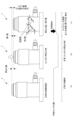
図1は、本発明の第1の実施形態における位置検出装置1の構成を示す模式図である。図1に示すように、本実施形態における位置検出装置1は、固定部10と、固定部10上に固定された1対の磁気センサ21,22と、信号線12を介して磁気センサ21,22に接続された検出部30と、例えばマシニングセンタの工具などの検出対象により移動させられる可動体2に取り付けられた磁石40とを含んでいる。可動体2は、矢印で示すようにX方向(第1の方向)に沿って移動可能となっており、この可動体2に取り付けられた磁石40は、X方向に沿って延びる移動経路M上を移動するように構成されている。位置検出装置1は、このようにX方向に移動可能な可動体2(ひいてはマシニングセンタの工具などの検出対象)が所定の位置(図1の基準線S)にあるか否かを検出するものである。
〔2.1 磁石の大きさ〕
磁石40及びセンサ基板は、精密機器に組み込むために出来るだけ小さいことが要求される。そこで、磁石40は、5mm角以内、又はφ5mm以下とすることが好適である。一方で、位置検出装置1の組み立て作業のしやすさを考慮すると、磁石40は適度な大きさを有することが望まれるため、磁石40は、1.5mm角以上とすることが好適である。
磁石40は磁場が強いほど、S/N比の値が良くなると共に、繰り返し精度が良くなる。すなわち、磁石40は、大きく厚いことが望まれる。また、磁気センサ21及び磁気センサ22と磁石40との距離がより近いことが望まれる。
図4は、磁気センサ21及び磁気センサ22と磁石40とのギャップを0.8mm、磁石40の厚み(Z方向の長さ)を1.0mmとした際の磁石の形状と最大磁束の関係を示すグラフである。図4中の各々の線は、磁石40のY方向の長さを示す。すなわち、図4は、磁石40のY方向の長さが、1mm、2mm、3mm、4mm、及び5mmの各々の場合において、磁石40のX方向の長さを変化させた場合の磁束密度の値の変化を示している。図4のグラフから分かるように、磁石40のX方向の長さは、1.5mmを下回ると磁束密度の値が小さすぎる一方で、3mmを超えても、磁束密度の値にあまり変化はない。すなわち、磁石40のX方向の長さは、1.5~3mmとすることが好適である。一方で、磁石40のY方向の長さは、2mm~4mmとすることが好適である。
図5は、磁石40のX方向及びY方向の長さを、2mm×3mm及び3mm×4mmとした場合の、磁石40のZ方向の長さ(厚み)と磁束密度との関係を示すグラフである。図5のグラフに示されるように、磁石40の厚みが1mmを下回ると磁束密度が小さすぎる一方で、厚みが3mmを超えると、磁束密度の値にあまり変化がない。すなわち、磁石40の厚みは、1mm~3mmとすることが好適である。
図6は、磁気センサ21及び磁気センサ22のトラックずれと、磁石40が長方形だった場合の位置関係を示す図である。図6に示すように、磁石40の磁場は、長手方向をY方向とするような楕円状となっているため、トラックずれの影響は小さくなる。
図7は、磁気センサ21及び磁気センサ22と磁石40とのギャップが0.8mm、磁石40のX方向、Y方向、Z方向の長さが3mm×4mm×1mmだった場合の、トラック方向の磁気センサ21及び磁気センサ22のずれと、出力分布との関係を示すグラフである。磁石40は長手方向をY方向とする長方形の形状であるが、この場合、トラック方向のずれが0.3mmあったとしても、出力の減衰率は2%の範囲に収まる。このことからも、磁石40は、長手方向がY方向となるような長方形とすることが好適であることが分かる。
磁石40は、強く、錆びにくく、温度係数が良い材質が望ましい。より具体的には、温度係数が-0.03%/℃のサマリュウムコバルト磁石や、-0.13%/℃の防錆処理をしたネオジム磁石が好適である。
1対の磁気センサ21及び磁気センサ22を表面実装する場合、磁気センサ21と磁気センサ22とを、略1.5mm以上離すことが好適である。
1対の磁気センサ21及び磁気センサ22の出力の最大変化率を得られる磁石40のX方向の長さは、磁気センサ21と磁気センサ22との実装距離に略等しいので、上記のように、磁気センサ21と磁気センサ22とが略1.5mm以上離れている場合、磁石40のX方向の長さも略1.5mm以上の長さとすることが好適である。
図8は、1対の磁気センサ21及び磁気センサ22と磁石40とのギャップが0.8mmであり、磁石のX方向、Y方向、及びZ方向の長さが、3mm×4mm×1mmであると共に、磁石40のX方向の長さが、磁気センサ21と磁気センサ22との実装距離に略等しい場合における、磁石40の位置と、磁気センサ21及び磁気センサ22の出力変化率との関係を示すグラフである。図8に示されるように、磁石40の位置が0、すなわち磁石40が基準線上に位置したとき、磁気センサ21及び磁気センサ22の出力変化率の絶対値の双方が略最大となっている。
上記の位置検出装置1の内部データである磁力データ(センサデータ)を監視することで、1対の磁気センサ21及び磁気センサ22の状態を把握することにより、位置検出装置1の故障診断をすることが可能である。より詳細には、内部データを監視することにより、位置検出装置1のメンテナンス時期の診断、1対の磁気センサ21及び磁気センサ22の故障の診断、位置検出装置1の使用環境診断が可能となる。
図13に示す例においては、(c)に示すように、位置検出装置1のコンタクト11が摺動する領域に、切削液や切り粉が付着している。このため、(b)から(c)に至る際、コンタクト11は正常な位置まで復帰しない。したがって、(a)から(b)に至る際のコンタクト11の押込み量よりも、(b)から(c)に至る際のコンタクト11の戻り量は小さくなる。また、内部センサの値に関しても、コンタクト11の押込み前の値よりも、コンタクト11を押し込んでから戻った後の値は小さくなる。
以上述べたように、本発明の一態様によれば、長寿命で、検出精度が高く、安定して位置検出を行うことができる位置検出装置が提供される。この位置検出装置は、第1の方向に沿って延びる移動経路上を可動体とともに移動するように構成される磁石を備える。この磁石は、上記第1の方向に垂直な第2の方向において異なる磁極を有する。また、上記位置検出装置は、上記移動経路から上記第2の方向に等しい距離だけ離間するとともに、上記第2の方向に延びる基準線から等しい距離に配置された1対の磁気センサを備える。上記1対の磁気センサは、同一のセンサ特性を有する。上記位置検出装置は、上記1対の磁気センサの双方の出力変化率の絶対値が略最大となったときに、上記磁石が上記基準線上に位置したことを検出するように構成される検出部を備える。
2 可動体
10 固定部
21,22 磁気センサ
30 検出部
40 磁石
41,42 磁極
M 移動経路
S 基準線
Claims (12)
- 第1の方向に沿って延びる移動経路上を可動体とともに移動するように構成される磁石であって、前記第1の方向に垂直な第2の方向において異なる磁極を有する磁石と、
前記移動経路から前記第2の方向に等しい距離だけ離間するとともに、前記第2の方向に延びる基準線から等しい距離に配置された1対の磁気センサであって、同一のセンサ特性を有する1対の磁気センサと、
前記1対の磁気センサ間の距離と、前記磁石の前記第1の方向の長さとが等しい構成により、前記1対の磁気センサの双方の出力変化率の絶対値が略最大となった状態で前記磁石が前記基準線上に位置したことを検出するように構成される検出部と
を備える位置検出装置。 - 前記磁石の前記第1の方向の長さは、略1.5mm以上である、請求項1に記載の位置検出装置。
- 前記磁石は略5mm角以内の大きさである、請求項1又は請求項2に記載の位置検出装置。
- 前記磁石は略1.5mm角以上の大きさである、請求項1から請求項3のいずれか1項に記載の位置検出装置。
- 前記磁石は、前記第1の方向の長さが略1.5mm~3mmであり、前記第2の方向の長さが略2mm以上、略4mm以下である、請求項1から請求項4のいずれか1項に記載の位置検出装置。
- 前記磁石は、前記第1の方向及び前記第2の方向に垂直な第3の方向の長さが略1mm以上、略3mm以下である、請求項1から請求項5のいずれか1項に記載の位置検出装置。
- 前記磁石の形状は長方形であり、当該長方形の対称軸が、前記第1の方向及び前記第2の方向に一致する、請求項1から請求項6のいずれか1項に記載の位置検出装置。
- 前記1対の磁気センサは、前記第1の方向に、略1.5mm以上離間する、請求項1から請求項7のいずれか1項に記載の位置検出装置。
- 前記磁石の前記移動経路の中心軸と前記1対の磁気センサとの間の距離は、略0.3mm以上、略0.8mm以下である、請求項1から請求項8のいずれか1項に記載の位置検出装置。
- 前記磁石は、サマリュウムコバルト磁石又は防錆処理をしたネオジム磁石である、請求項1から請求項9のいずれか1項に記載の位置検出装置。
- 前記位置検出装置の待機時における前記磁気センサの出力と、前記磁石を前記第1の方向に移動させた後、前記磁石が前記第1の方向とは逆方向に戻り終えた時点の前記磁気センサの出力とを比較する比較部と、
前記比較部による当該比較結果に基づいて、前記位置検出装置の異常を診断する第1診断部とを更に備える、請求項1から請求項10のいずれか1項に記載の位置検出装置。 - 前記位置検出装置の待機時における振動による、前記磁気センサの出力の値の変動に基づいて、前記位置検出装置の異常を診断する第2診断部を更に備える、請求項1から請求項10のいずれか1項に記載の位置検出装置。
Priority Applications (4)
| Application Number | Priority Date | Filing Date | Title |
|---|---|---|---|
| JP2020124015A JP7540698B2 (ja) | 2020-07-20 | 2020-07-20 | 位置検出装置 |
| CN202180046249.4A CN115735099B (zh) | 2020-07-20 | 2021-05-28 | 位置检测装置 |
| PCT/JP2021/020416 WO2022018969A1 (ja) | 2020-07-20 | 2021-05-28 | 位置検出装置 |
| EP21846287.7A EP4174445B1 (en) | 2020-07-20 | 2021-05-28 | Position detection device |
Applications Claiming Priority (1)
| Application Number | Priority Date | Filing Date | Title |
|---|---|---|---|
| JP2020124015A JP7540698B2 (ja) | 2020-07-20 | 2020-07-20 | 位置検出装置 |
Publications (2)
| Publication Number | Publication Date |
|---|---|
| JP2022020490A JP2022020490A (ja) | 2022-02-01 |
| JP7540698B2 true JP7540698B2 (ja) | 2024-08-27 |
Family
ID=79728641
Family Applications (1)
| Application Number | Title | Priority Date | Filing Date |
|---|---|---|---|
| JP2020124015A Active JP7540698B2 (ja) | 2020-07-20 | 2020-07-20 | 位置検出装置 |
Country Status (4)
| Country | Link |
|---|---|
| EP (1) | EP4174445B1 (ja) |
| JP (1) | JP7540698B2 (ja) |
| CN (1) | CN115735099B (ja) |
| WO (1) | WO2022018969A1 (ja) |
Citations (9)
| Publication number | Priority date | Publication date | Assignee | Title |
|---|---|---|---|---|
| JP2001221608A (ja) | 2000-02-14 | 2001-08-17 | Ckd Corp | 回転位置検出装置及び回転位置決め装置 |
| US20070096723A1 (en) | 2005-11-01 | 2007-05-03 | Honeywell International Inc. | Method and system for linear positioning |
| WO2007069680A1 (ja) | 2005-12-16 | 2007-06-21 | Asahi Kasei Emd Corporation | 位置検出装置 |
| JP2008101932A (ja) | 2006-10-17 | 2008-05-01 | Tokai Rika Co Ltd | 磁気式位置検出装置 |
| JP2010096540A (ja) | 2008-10-14 | 2010-04-30 | Asahi Kasei Electronics Co Ltd | 位置検出装置及びその位置検出装置を用いた電子機器 |
| JP2010197373A (ja) | 2009-01-29 | 2010-09-09 | Denso Corp | ストロークセンサおよび回転角センサ |
| JP2011169696A (ja) | 2010-02-17 | 2011-09-01 | Asahi Kasei Electronics Co Ltd | 磁気センサユニット |
| JP2011220832A (ja) | 2010-04-09 | 2011-11-04 | Tokai Rika Co Ltd | 位置検出装置及びシフトレバー装置 |
| WO2020158677A1 (ja) | 2019-01-31 | 2020-08-06 | 株式会社メトロール | 位置検出装置 |
Family Cites Families (6)
| Publication number | Priority date | Publication date | Assignee | Title |
|---|---|---|---|---|
| JPS6183710A (ja) * | 1984-09-29 | 1986-04-28 | Tsutomu Hino | コ−ン貫入試験機 |
| JP3582208B2 (ja) * | 1996-02-26 | 2004-10-27 | 松下電工株式会社 | 埋設物の位置検出装置 |
| JP2008183699A (ja) | 2007-01-30 | 2008-08-14 | Metrol Ltd | 接触式位置センサ |
| JP5155966B2 (ja) * | 2009-08-12 | 2013-03-06 | 旭化成エレクトロニクス株式会社 | 位置検出装置 |
| JP5646946B2 (ja) * | 2010-10-14 | 2014-12-24 | 旭化成エレクトロニクス株式会社 | 位置検出装置及びそれを備えた電子機器 |
| CN107076808B (zh) * | 2014-09-26 | 2019-09-20 | 旭化成微电子株式会社 | 磁传感器 |
-
2020
- 2020-07-20 JP JP2020124015A patent/JP7540698B2/ja active Active
-
2021
- 2021-05-28 EP EP21846287.7A patent/EP4174445B1/en active Active
- 2021-05-28 CN CN202180046249.4A patent/CN115735099B/zh active Active
- 2021-05-28 WO PCT/JP2021/020416 patent/WO2022018969A1/ja not_active Ceased
Patent Citations (9)
| Publication number | Priority date | Publication date | Assignee | Title |
|---|---|---|---|---|
| JP2001221608A (ja) | 2000-02-14 | 2001-08-17 | Ckd Corp | 回転位置検出装置及び回転位置決め装置 |
| US20070096723A1 (en) | 2005-11-01 | 2007-05-03 | Honeywell International Inc. | Method and system for linear positioning |
| WO2007069680A1 (ja) | 2005-12-16 | 2007-06-21 | Asahi Kasei Emd Corporation | 位置検出装置 |
| JP2008101932A (ja) | 2006-10-17 | 2008-05-01 | Tokai Rika Co Ltd | 磁気式位置検出装置 |
| JP2010096540A (ja) | 2008-10-14 | 2010-04-30 | Asahi Kasei Electronics Co Ltd | 位置検出装置及びその位置検出装置を用いた電子機器 |
| JP2010197373A (ja) | 2009-01-29 | 2010-09-09 | Denso Corp | ストロークセンサおよび回転角センサ |
| JP2011169696A (ja) | 2010-02-17 | 2011-09-01 | Asahi Kasei Electronics Co Ltd | 磁気センサユニット |
| JP2011220832A (ja) | 2010-04-09 | 2011-11-04 | Tokai Rika Co Ltd | 位置検出装置及びシフトレバー装置 |
| WO2020158677A1 (ja) | 2019-01-31 | 2020-08-06 | 株式会社メトロール | 位置検出装置 |
Also Published As
| Publication number | Publication date |
|---|---|
| JP2022020490A (ja) | 2022-02-01 |
| CN115735099A (zh) | 2023-03-03 |
| EP4174445C0 (en) | 2025-07-16 |
| WO2022018969A1 (ja) | 2022-01-27 |
| EP4174445A1 (en) | 2023-05-03 |
| EP4174445A4 (en) | 2023-12-06 |
| EP4174445B1 (en) | 2025-07-16 |
| CN115735099B (zh) | 2025-09-26 |
Similar Documents
| Publication | Publication Date | Title |
|---|---|---|
| EP3814076B1 (en) | Multi-axis force and torque sensor and robot having the same | |
| KR101733310B1 (ko) | 자기 검출 장치 및 이를 포함하는 토크 센서 | |
| US8115479B2 (en) | Rotation-angle-detecting apparatus, rotating machine, and rotation-angle-detecting method | |
| EP2579002B1 (en) | Magnetic encoder | |
| US10209095B2 (en) | Eddy current sensor | |
| US11150109B2 (en) | Displacement detecting device and continuously variable transmission device | |
| US20150153203A1 (en) | System for Ascertaining the Number of Revolutions of a Rotationally Mounted Shaft, and Method for Ascertaining the Number of Revolutions of a Rotationally Mounted Shaft | |
| US11555719B2 (en) | Actuator assembly having rotary sensor responsive to rotation of magnet | |
| JP7540698B2 (ja) | 位置検出装置 | |
| CN114391090B (zh) | 带有霍尔传感器和磁体的位移测量装置 | |
| WO2018025121A1 (en) | Linear position sensor. | |
| JPWO2014203862A1 (ja) | 電流センサ | |
| JP5395751B2 (ja) | ポジションセンサ | |
| JP3400641B2 (ja) | 直線変位検出装置 | |
| CN109661521B (zh) | 异物检测装置及线性引导件 | |
| KR101272010B1 (ko) | 미소 변위 측정 센서 | |
| KR20230152706A (ko) | 자석 센서 및 강자성 극 | |
| JP2003156364A (ja) | スライド位置検出装置を備えた直動装置 | |
| US20220034642A1 (en) | Rotary angle detecting device | |
| US20250271286A1 (en) | High precision angular measurement system | |
| JP7592775B2 (ja) | ストロークセンサとこれを備えたストロークセンサ組立体 | |
| JP2021143833A (ja) | 磁気検出装置 | |
| CN219608061U (zh) | 一种感应式磁编码器 | |
| US20260002799A1 (en) | Magnet-based rotational angle sensor system | |
| Bratland et al. | Linear position sensing using magnetoresistive sensors |
Legal Events
| Date | Code | Title | Description |
|---|---|---|---|
| A621 | Written request for application examination |
Free format text: JAPANESE INTERMEDIATE CODE: A621 Effective date: 20230720 |
|
| A131 | Notification of reasons for refusal |
Free format text: JAPANESE INTERMEDIATE CODE: A131 Effective date: 20240402 |
|
| A521 | Request for written amendment filed |
Free format text: JAPANESE INTERMEDIATE CODE: A523 Effective date: 20240522 |
|
| TRDD | Decision of grant or rejection written | ||
| A01 | Written decision to grant a patent or to grant a registration (utility model) |
Free format text: JAPANESE INTERMEDIATE CODE: A01 Effective date: 20240709 |
|
| A61 | First payment of annual fees (during grant procedure) |
Free format text: JAPANESE INTERMEDIATE CODE: A61 Effective date: 20240807 |
|
| R150 | Certificate of patent or registration of utility model |
Ref document number: 7540698 Country of ref document: JP Free format text: JAPANESE INTERMEDIATE CODE: R150 |