JP7614190B2 - 測定対象物の機能性を検査するための部品 - Google Patents
測定対象物の機能性を検査するための部品 Download PDFInfo
- Publication number
- JP7614190B2 JP7614190B2 JP2022519149A JP2022519149A JP7614190B2 JP 7614190 B2 JP7614190 B2 JP 7614190B2 JP 2022519149 A JP2022519149 A JP 2022519149A JP 2022519149 A JP2022519149 A JP 2022519149A JP 7614190 B2 JP7614190 B2 JP 7614190B2
- Authority
- JP
- Japan
- Prior art keywords
- electrical
- receiving structure
- dut
- contact
- test
- Prior art date
- Legal status (The legal status is an assumption and is not a legal conclusion. Google has not performed a legal analysis and makes no representation as to the accuracy of the status listed.)
- Active
Links
Images


Classifications
-
- G—PHYSICS
- G01—MEASURING; TESTING
- G01R—MEASURING ELECTRIC VARIABLES; MEASURING MAGNETIC VARIABLES
- G01R1/00—Details of instruments or arrangements of the types included in groups G01R5/00 - G01R13/00 and G01R31/00
- G01R1/02—General constructional details
- G01R1/04—Housings; Supporting members; Arrangements of terminals
- G01R1/0408—Test fixtures or contact fields; Connectors or connecting adaptors; Test clips; Test sockets
-
- G—PHYSICS
- G01—MEASURING; TESTING
- G01R—MEASURING ELECTRIC VARIABLES; MEASURING MAGNETIC VARIABLES
- G01R31/00—Arrangements for testing electric properties; Arrangements for locating electric faults; Arrangements for electrical testing characterised by what is being tested not provided for elsewhere
- G01R31/28—Testing of electronic circuits, e.g. by signal tracer
- G01R31/2801—Testing of printed circuits, backplanes, motherboards, hybrid circuits or carriers for multichip packages [MCP]
- G01R31/2806—Apparatus therefor, e.g. test stations, drivers, analysers, conveyors
- G01R31/2808—Holding, conveying or contacting devices, e.g. test adapters, edge connectors, extender boards
-
- G—PHYSICS
- G01—MEASURING; TESTING
- G01R—MEASURING ELECTRIC VARIABLES; MEASURING MAGNETIC VARIABLES
- G01R31/00—Arrangements for testing electric properties; Arrangements for locating electric faults; Arrangements for electrical testing characterised by what is being tested not provided for elsewhere
- G01R31/28—Testing of electronic circuits, e.g. by signal tracer
- G01R31/317—Testing of digital circuits
- G01R31/3181—Functional testing
- G01R31/319—Tester hardware, i.e. output processing circuits
- G01R31/31903—Tester hardware, i.e. output processing circuits tester configuration
- G01R31/31905—Interface with the device under test [DUT], e.g. arrangements between the test head and the DUT, mechanical aspects, fixture
Landscapes
- Engineering & Computer Science (AREA)
- Physics & Mathematics (AREA)
- General Physics & Mathematics (AREA)
- General Engineering & Computer Science (AREA)
- Computer Hardware Design (AREA)
- Microelectronics & Electronic Packaging (AREA)
- Electrotherapy Devices (AREA)
- Tests Of Electronic Circuits (AREA)
Description
a)チェックの第1段階は、すべての電気/電子部品の機能を保証し、可能性のある低温はんだ付け箇所を除外するために、電子部品および電気部品が取り付けられたプリント回路基板をテストすることを含む。
2:試験モジュール
3:制御および分析ユニット
4:電気的追加部品
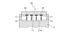
5:第1受入構造
6:電気回路基板
7:電気/電子部品
8:グロメット板
9:電気導体
10:コンタクト
11:筐体
12:医療用インプラント
13:ヘッド部
14:ソケット
15:接触面
16:凹部
17:接触電極
18:ケーブル接続
19:コンタクトピン
20:対向電極
21:第2受入構造
22,22’:ケーブル接続
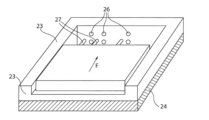
23:アダプタモジュール
24:接合輪郭
25:第3受入構造
26:ソケット
27:プラグコンタクトピン
Claims (13)
- Device Under Test(DUT)と呼ばれる測定対象物、すなわち、医療用インプラントまたは医療用インプラントの少なくとも一部の形態、の機能性を検査するための部品であって、
a)試験信号発生器、
b)前記試験信号発生器に対して接続され、少なくとも1つの接触電極を有する第1受入構造を備える試験モジュールであって、その中に、取り外し可能な方法で前記DUTに対して堅固に接続されたアダプタモジュールが挿入可能であり、少なくとも1つの電気接点を形成する、試験モジュール、
c)前記試験信号発生器および前記試験モジュールに対して直接または間接的に無線または有線で接続される制御および分析ユニット、
を備え、
前記試験モジュールは、第2受入構造を備え、
前記第2受入構造は、前記第1受入構造に対して空間的に固定されて配置され、電気エネルギーおよび/または信号伝送のために前記DUTと非接触で相互作用する電気的追加構成要素である、誘導コイルまたは信号アンテナアセンブリを挿入することができる、
部品。 - 前記電気的追加構成要素は、誘導コイルおよび/または信号アンテナを備える、請求項1記載の部品。
- 前記制御および分析ユニットは、前記電気的追加構成要素と無線または有線接続されている、請求項1または2記載の部品。
- 前記第1受入構造は、少なくとも1つの接触面を備え、
前記接触面は前記アダプタモジュールに対して接触させることができ、その上に少なくとも1つの接触電極が配置され、前記アダプタモジュールが前記第1受入構造内に挿入されたときの状態は、前記アダプタモジュールによって提供される対向電極とインターロック接触しかつ摩擦接触している、
請求項1から3のいずれか1項記載の部品。 - 前記アダプタモジュールは、第3受入構造を備え、
前記第3受入構造は、前記DUTを挿入することができ少なくとも1つの電気接点を形成する、少なくとも1つの接点電極を有する、
請求項1から4のいずれか1項記載の部品。 - 前記第3受入構造は、前記DUTと接触させることができ、その上に少なくとも1つの接触電極が配置された、少なくとも1つの接触面を備え、
前記接触電極は、DUTが前記第3受入構造に対して挿入されたときの状態で、摩擦およびインターロック方式で前記DUTにより提供される対向電極と接触する、
請求項5記載の部品。 - 前記少なくとも1つの接触電極および対向電極は、プラグソケット構造の形態で構成される、請求項4から6のいずれか1項記載の部品。
- 前記少なくとも1つの接触電極および/または対向電極は、ばね荷重の、偏向可能に支持されたコンタクトピンの形態で構成される、請求項4から6のいずれか1項記載の部品。
- 前記DUTは、
医療用活性インプラントの電気回路基板、
電気入出力リードを有する電気回路基板、
少なくとも1つの電気接点アセンブリを有する医療用活性インプラント、
のうち少なくともいずれかの電気部品である、
請求項1から8のいずれか1項記載の部品。 - 前記医療用活性インプラントは、埋め込み型パルス発生器(IPG)である、請求項9記載の部品。
- 前記試験信号発生器はECG信号を生成する、請求項1から10のいずれか1項記載の部品。
- 前記アダプタモジュール内の前記第3受入構造は、前記DUTに対して個別に整合され、
異なるように設計された前記第3受入構造を有する少なくとも2つのアダプタモジュールは、前記試験モジュールの前記第1受入構造に対して挿入されるようにそれぞれ均一に設計される、
請求項5または6記載の部品。 - ソフトウェア更新の一部として医療用インプラントを診断および/または更新するための、請求項1から12のいずれか1項記載の部品。
Applications Claiming Priority (3)
| Application Number | Priority Date | Filing Date | Title |
|---|---|---|---|
| DE102019215126.4 | 2019-10-01 | ||
| DE102019215126.4A DE102019215126A1 (de) | 2019-10-01 | 2019-10-01 | Anordnung zur Funktionsüberprüfung eines Meßobjektes |
| PCT/EP2020/077481 WO2021064087A1 (de) | 2019-10-01 | 2020-10-01 | ANORDNUNG ZUR FUNKTIONSÜBERPRÜFUNG EINES MEßOBJEKTES |
Publications (2)
| Publication Number | Publication Date |
|---|---|
| JP2022550339A JP2022550339A (ja) | 2022-12-01 |
| JP7614190B2 true JP7614190B2 (ja) | 2025-01-15 |
Family
ID=72852598
Family Applications (1)
| Application Number | Title | Priority Date | Filing Date |
|---|---|---|---|
| JP2022519149A Active JP7614190B2 (ja) | 2019-10-01 | 2020-10-01 | 測定対象物の機能性を検査するための部品 |
Country Status (7)
| Country | Link |
|---|---|
| US (1) | US11815543B2 (ja) |
| EP (1) | EP4038396B1 (ja) |
| JP (1) | JP7614190B2 (ja) |
| CN (1) | CN114502969A (ja) |
| DE (1) | DE102019215126A1 (ja) |
| ES (1) | ES3006438T3 (ja) |
| WO (1) | WO2021064087A1 (ja) |
Citations (6)
| Publication number | Priority date | Publication date | Assignee | Title |
|---|---|---|---|---|
| JP2007107930A (ja) | 2005-10-11 | 2007-04-26 | Sony Corp | 検査回路および検査システム |
| US20070126448A1 (en) | 2005-12-05 | 2007-06-07 | Hubscher Ronald A | System-on-a-chip pipeline tester and method |
| JP2008089493A (ja) | 2006-10-04 | 2008-04-17 | Yokogawa Electric Corp | Icテスタ用組み込みソフトウェアのデバッグ方法 |
| US20110022524A1 (en) | 2009-07-21 | 2011-01-27 | Monahan Brian H | Printed circuit board with passive rfid transponder |
| US20140312187A1 (en) | 2013-04-19 | 2014-10-23 | Pkc Electronics Oy | Test adapter |
| US20190271719A1 (en) | 2018-03-01 | 2019-09-05 | Rohde & Schwarz Gmbh & Co. Kg | Method and apparatus used for testing a device under test |
Family Cites Families (30)
| Publication number | Priority date | Publication date | Assignee | Title |
|---|---|---|---|---|
| JPH039282A (ja) * | 1989-06-05 | 1991-01-17 | Kawasaki Steel Corp | コンフイグラブル電子回路ボード用アダプタ |
| JPH0498171A (ja) * | 1990-08-15 | 1992-03-30 | Kawasaki Steel Corp | 集積回路搭載アダプタ及びこれを用いた電子回路ボードの設計方法 |
| WO1999001772A1 (de) * | 1997-07-03 | 1999-01-14 | Luther & Maelzer Gmbh | Leiterplattenprüfvorrichtung |
| US6002264A (en) | 1997-08-19 | 1999-12-14 | Hewlett-Packard Company | Interconnect adapter to printed circuit assembly for testing in an operational environment |
| SE9704521D0 (sv) * | 1997-12-04 | 1997-12-04 | Pacesetter Ab | Medical implant |
| US6567703B1 (en) * | 2000-11-08 | 2003-05-20 | Medtronic, Inc. | Implantable medical device incorporating miniaturized circuit module |
| US6535006B2 (en) * | 2000-12-22 | 2003-03-18 | Intel Corporation | Test socket and system |
| AUPS322602A0 (en) * | 2002-06-28 | 2002-07-18 | Cochlear Limited | Coil and cable tester |
| US20040010388A1 (en) | 2002-07-10 | 2004-01-15 | Cherif Ahrikencheikh | Method and apparatus for determining proper trace widths for printed circuit board of wireless test fixture |
| AU2003275636A1 (en) * | 2002-10-31 | 2004-05-25 | Advantest Corporation | Connection unit, board mounting device to be measured, probe card, and device interface unit |
| US7307427B2 (en) * | 2005-07-23 | 2007-12-11 | Agilent Technologies, Inc. | Method and apparatus for engineering a testability interposer for testing sockets and connectors on printed circuit boards |
| DE202006000739U1 (de) * | 2005-12-23 | 2006-04-20 | Weiherer, Johann | Vorrichtung zum Testen elektronischer Bauelemente, insbesondere Bauelemente mit integrierten Schaltungen sowie Kontaktsockel für eine solche Vorrichtung |
| US7688077B2 (en) * | 2007-08-23 | 2010-03-30 | Advantest Corporation | Test system and daughter unit |
| US7915909B2 (en) * | 2007-12-18 | 2011-03-29 | Sibeam, Inc. | RF integrated circuit test methodology and system |
| WO2010034080A1 (en) * | 2008-09-26 | 2010-04-01 | Cochlear Limited | Medical implant with integrity testing |
| US20130200915A1 (en) * | 2012-02-06 | 2013-08-08 | Peter G. Panagas | Test System with Test Trays and Automated Test Tray Handling |
| US9372227B2 (en) * | 2013-03-11 | 2016-06-21 | Taiwan Semiconductor Manufacturing Co., Ltd. | Integrated circuit test system and method |
| US9265947B2 (en) * | 2013-11-08 | 2016-02-23 | Boston Scientific Neuromodulation Corporation | Circuit board for an implantable medical device, and method of fabricating and testing |
| US9588173B2 (en) * | 2013-12-17 | 2017-03-07 | Keyssa, Inc. | Waveguides for capturing close-proximity electromagnetic radiation transmitted by wireless chips during testing on automated test equipment (ATE) |
| EP2990817A1 (de) * | 2014-09-01 | 2016-03-02 | Siemens Aktiengesellschaft | Kompakte Prüfanordnung für Leiterplatten |
| DE102014014943A1 (de) * | 2014-10-07 | 2016-04-07 | Neuroloop GmbH | Implantierbare Elektrodenanordnung |
| US9851377B2 (en) * | 2015-09-03 | 2017-12-26 | Rohde & Schwarz Asia Pte, Ltd. | Universal holding apparatus for holding a device under test |
| CN105486999A (zh) * | 2015-11-27 | 2016-04-13 | 中国电子科技集团公司第三十八研究所 | 基于pxi总线的边界扫描数字电路测试系统及其测试方法 |
| KR102581480B1 (ko) * | 2016-07-27 | 2023-09-21 | 삼성전자주식회사 | 반도체 패키지를 위한 테스트 보드, 테스트 시스템 및 반도체 패키지의 제조 방법 |
| CN107064776B (zh) | 2017-04-20 | 2019-10-25 | 北京品驰医疗设备有限公司 | 一种对医疗设备电路板进行可靠性试验的系统及方法 |
| CN109425812B (zh) * | 2017-08-28 | 2021-03-12 | 创意电子股份有限公司 | 半导体封装元件的检测系统及其热阻障层元件 |
| CN109143028B (zh) | 2018-07-23 | 2021-06-11 | 清华大学 | 一种便捷可靠的植入式医疗仪器自动检测方法 |
| CN109061439B (zh) * | 2018-07-23 | 2021-05-04 | 清华大学 | 用于多种有源植入医疗仪器的自动测试的方法 |
| CN109031096B (zh) * | 2018-07-23 | 2025-04-01 | 清华大学 | 适用于植入医疗设备整机自动测试系统的电路板 |
| CN109975640A (zh) | 2019-04-23 | 2019-07-05 | 创领心律管理医疗器械(上海)有限公司 | 测试架以及包含该测试架的测试装置 |
-
2019
- 2019-10-01 DE DE102019215126.4A patent/DE102019215126A1/de not_active Ceased
-
2020
- 2020-10-01 JP JP2022519149A patent/JP7614190B2/ja active Active
- 2020-10-01 CN CN202080069736.8A patent/CN114502969A/zh active Pending
- 2020-10-01 WO PCT/EP2020/077481 patent/WO2021064087A1/de not_active Ceased
- 2020-10-01 ES ES20790201T patent/ES3006438T3/es active Active
- 2020-10-01 EP EP20790201.6A patent/EP4038396B1/de active Active
- 2020-10-01 US US17/763,764 patent/US11815543B2/en active Active
Patent Citations (6)
| Publication number | Priority date | Publication date | Assignee | Title |
|---|---|---|---|---|
| JP2007107930A (ja) | 2005-10-11 | 2007-04-26 | Sony Corp | 検査回路および検査システム |
| US20070126448A1 (en) | 2005-12-05 | 2007-06-07 | Hubscher Ronald A | System-on-a-chip pipeline tester and method |
| JP2008089493A (ja) | 2006-10-04 | 2008-04-17 | Yokogawa Electric Corp | Icテスタ用組み込みソフトウェアのデバッグ方法 |
| US20110022524A1 (en) | 2009-07-21 | 2011-01-27 | Monahan Brian H | Printed circuit board with passive rfid transponder |
| US20140312187A1 (en) | 2013-04-19 | 2014-10-23 | Pkc Electronics Oy | Test adapter |
| US20190271719A1 (en) | 2018-03-01 | 2019-09-05 | Rohde & Schwarz Gmbh & Co. Kg | Method and apparatus used for testing a device under test |
Also Published As
| Publication number | Publication date |
|---|---|
| CN114502969A (zh) | 2022-05-13 |
| ES3006438T3 (en) | 2025-03-18 |
| DE102019215126A1 (de) | 2021-04-01 |
| US20220341988A1 (en) | 2022-10-27 |
| EP4038396A1 (de) | 2022-08-10 |
| EP4038396C0 (de) | 2024-12-04 |
| EP4038396B1 (de) | 2024-12-04 |
| US11815543B2 (en) | 2023-11-14 |
| WO2021064087A1 (de) | 2021-04-08 |
| JP2022550339A (ja) | 2022-12-01 |
Similar Documents
| Publication | Publication Date | Title |
|---|---|---|
| TW521151B (en) | Pin block structure for mounting contact pins | |
| CN211785935U (zh) | 一种用于集成电路芯片的辐射测试系统 | |
| JP2002202344A (ja) | コンタクトピンモジュールおよびそれを備える検査装置 | |
| JPH10239371A (ja) | 基板検査装置および基板検査方法 | |
| EP0862061A2 (en) | Circuit board inspection apparatus and method | |
| JP2016536069A (ja) | 埋込可能医療デバイスの回路基板並びに組み立て及び検査方法 | |
| US7307427B2 (en) | Method and apparatus for engineering a testability interposer for testing sockets and connectors on printed circuit boards | |
| JP2011053035A (ja) | 基板検査装置 | |
| KR20210133231A (ko) | 임피던스 표준 | |
| JP7614190B2 (ja) | 測定対象物の機能性を検査するための部品 | |
| US11067601B2 (en) | High accuracy electrical test interconnection device and method for electrical circuit board testing | |
| US10739382B2 (en) | Testing apparatus having a configurable probe fixture | |
| JP5351171B2 (ja) | 回路ボードアッセンブリ及び誤挿入検出装置 | |
| JPS61182237A (ja) | プロ−ブカ−ド | |
| CN209117732U (zh) | 一种在线检测电控工装 | |
| EP1921459A1 (en) | Calibration board for electronic component testing apparatus | |
| EP4375677A1 (en) | Compact test fixture | |
| JPH0747790Y2 (ja) | 電子ビームテスタ | |
| JPH0274878A (ja) | プリント回路基板試験装置のためのコネクタ・システム | |
| JP2009103620A (ja) | 誤装着防止装置 | |
| JP2007281101A (ja) | 制御基板のプリント配線構造 | |
| JPH02248876A (ja) | プリント基盤テスト用のスーパーアダプタ | |
| JPS617640A (ja) | 実装集積回路装置の特性試験装置 | |
| JPH01159982A (ja) | 集積回路ソケット | |
| JPH0290588A (ja) | 印刷配線板 |
Legal Events
| Date | Code | Title | Description |
|---|---|---|---|
| RD01 | Notification of change of attorney |
Free format text: JAPANESE INTERMEDIATE CODE: A7426 Effective date: 20221101 |
|
| A521 | Request for written amendment filed |
Free format text: JAPANESE INTERMEDIATE CODE: A821 Effective date: 20221101 |
|
| A621 | Written request for application examination |
Free format text: JAPANESE INTERMEDIATE CODE: A621 Effective date: 20230719 |
|
| A131 | Notification of reasons for refusal |
Free format text: JAPANESE INTERMEDIATE CODE: A131 Effective date: 20240709 |
|
| A521 | Request for written amendment filed |
Free format text: JAPANESE INTERMEDIATE CODE: A523 Effective date: 20240828 |
|
| A131 | Notification of reasons for refusal |
Free format text: JAPANESE INTERMEDIATE CODE: A131 Effective date: 20241015 |
|
| A521 | Request for written amendment filed |
Free format text: JAPANESE INTERMEDIATE CODE: A523 Effective date: 20241025 |
|
| TRDD | Decision of grant or rejection written | ||
| A01 | Written decision to grant a patent or to grant a registration (utility model) |
Free format text: JAPANESE INTERMEDIATE CODE: A01 Effective date: 20241210 |
|
| A61 | First payment of annual fees (during grant procedure) |
Free format text: JAPANESE INTERMEDIATE CODE: A61 Effective date: 20241226 |
|
| R150 | Certificate of patent or registration of utility model |
Ref document number: 7614190 Country of ref document: JP Free format text: JAPANESE INTERMEDIATE CODE: R150 |