JP7637763B2 - 配線モジュール - Google Patents
配線モジュール Download PDFInfo
- Publication number
- JP7637763B2 JP7637763B2 JP2023512957A JP2023512957A JP7637763B2 JP 7637763 B2 JP7637763 B2 JP 7637763B2 JP 2023512957 A JP2023512957 A JP 2023512957A JP 2023512957 A JP2023512957 A JP 2023512957A JP 7637763 B2 JP7637763 B2 JP 7637763B2
- Authority
- JP
- Japan
- Prior art keywords
- nut
- bolt
- bus bar
- connection portion
- insulating protector
- Prior art date
- Legal status (The legal status is an assumption and is not a legal conclusion. Google has not performed a legal analysis and makes no representation as to the accuracy of the status listed.)
- Active
Links
Images


Classifications
-
- H—ELECTRICITY
- H01—ELECTRIC ELEMENTS
- H01M—PROCESSES OR MEANS, e.g. BATTERIES, FOR THE DIRECT CONVERSION OF CHEMICAL ENERGY INTO ELECTRICAL ENERGY
- H01M50/00—Constructional details or processes of manufacture of the non-active parts of electrochemical cells other than fuel cells, e.g. hybrid cells
- H01M50/20—Mountings; Secondary casings or frames; Racks, modules or packs; Suspension devices; Shock absorbers; Transport or carrying devices; Holders
- H01M50/204—Racks, modules or packs for multiple batteries or multiple cells
- H01M50/207—Racks, modules or packs for multiple batteries or multiple cells characterised by their shape
- H01M50/209—Racks, modules or packs for multiple batteries or multiple cells characterised by their shape adapted for prismatic or rectangular cells
-
- H—ELECTRICITY
- H01—ELECTRIC ELEMENTS
- H01M—PROCESSES OR MEANS, e.g. BATTERIES, FOR THE DIRECT CONVERSION OF CHEMICAL ENERGY INTO ELECTRICAL ENERGY
- H01M50/00—Constructional details or processes of manufacture of the non-active parts of electrochemical cells other than fuel cells, e.g. hybrid cells
- H01M50/20—Mountings; Secondary casings or frames; Racks, modules or packs; Suspension devices; Shock absorbers; Transport or carrying devices; Holders
- H01M50/204—Racks, modules or packs for multiple batteries or multiple cells
- H01M50/207—Racks, modules or packs for multiple batteries or multiple cells characterised by their shape
- H01M50/211—Racks, modules or packs for multiple batteries or multiple cells characterised by their shape adapted for pouch cells
-
- H—ELECTRICITY
- H01—ELECTRIC ELEMENTS
- H01M—PROCESSES OR MEANS, e.g. BATTERIES, FOR THE DIRECT CONVERSION OF CHEMICAL ENERGY INTO ELECTRICAL ENERGY
- H01M50/00—Constructional details or processes of manufacture of the non-active parts of electrochemical cells other than fuel cells, e.g. hybrid cells
- H01M50/20—Mountings; Secondary casings or frames; Racks, modules or packs; Suspension devices; Shock absorbers; Transport or carrying devices; Holders
- H01M50/249—Mountings; Secondary casings or frames; Racks, modules or packs; Suspension devices; Shock absorbers; Transport or carrying devices; Holders specially adapted for aircraft or vehicles, e.g. cars or trains
-
- H—ELECTRICITY
- H01—ELECTRIC ELEMENTS
- H01M—PROCESSES OR MEANS, e.g. BATTERIES, FOR THE DIRECT CONVERSION OF CHEMICAL ENERGY INTO ELECTRICAL ENERGY
- H01M50/00—Constructional details or processes of manufacture of the non-active parts of electrochemical cells other than fuel cells, e.g. hybrid cells
- H01M50/20—Mountings; Secondary casings or frames; Racks, modules or packs; Suspension devices; Shock absorbers; Transport or carrying devices; Holders
- H01M50/284—Mountings; Secondary casings or frames; Racks, modules or packs; Suspension devices; Shock absorbers; Transport or carrying devices; Holders with incorporated circuit boards, e.g. printed circuit boards [PCB]
-
- H—ELECTRICITY
- H01—ELECTRIC ELEMENTS
- H01M—PROCESSES OR MEANS, e.g. BATTERIES, FOR THE DIRECT CONVERSION OF CHEMICAL ENERGY INTO ELECTRICAL ENERGY
- H01M50/00—Constructional details or processes of manufacture of the non-active parts of electrochemical cells other than fuel cells, e.g. hybrid cells
- H01M50/20—Mountings; Secondary casings or frames; Racks, modules or packs; Suspension devices; Shock absorbers; Transport or carrying devices; Holders
- H01M50/296—Mountings; Secondary casings or frames; Racks, modules or packs; Suspension devices; Shock absorbers; Transport or carrying devices; Holders characterised by terminals of battery packs
-
- H—ELECTRICITY
- H01—ELECTRIC ELEMENTS
- H01M—PROCESSES OR MEANS, e.g. BATTERIES, FOR THE DIRECT CONVERSION OF CHEMICAL ENERGY INTO ELECTRICAL ENERGY
- H01M50/00—Constructional details or processes of manufacture of the non-active parts of electrochemical cells other than fuel cells, e.g. hybrid cells
- H01M50/20—Mountings; Secondary casings or frames; Racks, modules or packs; Suspension devices; Shock absorbers; Transport or carrying devices; Holders
- H01M50/298—Mountings; Secondary casings or frames; Racks, modules or packs; Suspension devices; Shock absorbers; Transport or carrying devices; Holders characterised by the wiring of battery packs
-
- H—ELECTRICITY
- H01—ELECTRIC ELEMENTS
- H01M—PROCESSES OR MEANS, e.g. BATTERIES, FOR THE DIRECT CONVERSION OF CHEMICAL ENERGY INTO ELECTRICAL ENERGY
- H01M50/00—Constructional details or processes of manufacture of the non-active parts of electrochemical cells other than fuel cells, e.g. hybrid cells
- H01M50/50—Current conducting connections for cells or batteries
- H01M50/502—Interconnectors for connecting terminals of adjacent batteries; Interconnectors for connecting cells outside a battery casing
- H01M50/503—Interconnectors for connecting terminals of adjacent batteries; Interconnectors for connecting cells outside a battery casing characterised by the shape of the interconnectors
-
- H—ELECTRICITY
- H01—ELECTRIC ELEMENTS
- H01M—PROCESSES OR MEANS, e.g. BATTERIES, FOR THE DIRECT CONVERSION OF CHEMICAL ENERGY INTO ELECTRICAL ENERGY
- H01M50/00—Constructional details or processes of manufacture of the non-active parts of electrochemical cells other than fuel cells, e.g. hybrid cells
- H01M50/50—Current conducting connections for cells or batteries
- H01M50/502—Interconnectors for connecting terminals of adjacent batteries; Interconnectors for connecting cells outside a battery casing
- H01M50/505—Interconnectors for connecting terminals of adjacent batteries; Interconnectors for connecting cells outside a battery casing comprising a single busbar
-
- H—ELECTRICITY
- H01—ELECTRIC ELEMENTS
- H01M—PROCESSES OR MEANS, e.g. BATTERIES, FOR THE DIRECT CONVERSION OF CHEMICAL ENERGY INTO ELECTRICAL ENERGY
- H01M50/00—Constructional details or processes of manufacture of the non-active parts of electrochemical cells other than fuel cells, e.g. hybrid cells
- H01M50/50—Current conducting connections for cells or batteries
- H01M50/502—Interconnectors for connecting terminals of adjacent batteries; Interconnectors for connecting cells outside a battery casing
- H01M50/507—Interconnectors for connecting terminals of adjacent batteries; Interconnectors for connecting cells outside a battery casing comprising an arrangement of two or more busbars within a container structure, e.g. busbar modules
-
- H—ELECTRICITY
- H01—ELECTRIC ELEMENTS
- H01M—PROCESSES OR MEANS, e.g. BATTERIES, FOR THE DIRECT CONVERSION OF CHEMICAL ENERGY INTO ELECTRICAL ENERGY
- H01M50/00—Constructional details or processes of manufacture of the non-active parts of electrochemical cells other than fuel cells, e.g. hybrid cells
- H01M50/50—Current conducting connections for cells or batteries
- H01M50/502—Interconnectors for connecting terminals of adjacent batteries; Interconnectors for connecting cells outside a battery casing
- H01M50/514—Methods for interconnecting adjacent batteries or cells
- H01M50/517—Methods for interconnecting adjacent batteries or cells by fixing means, e.g. screws, rivets or bolts
-
- H—ELECTRICITY
- H01—ELECTRIC ELEMENTS
- H01M—PROCESSES OR MEANS, e.g. BATTERIES, FOR THE DIRECT CONVERSION OF CHEMICAL ENERGY INTO ELECTRICAL ENERGY
- H01M50/00—Constructional details or processes of manufacture of the non-active parts of electrochemical cells other than fuel cells, e.g. hybrid cells
- H01M50/50—Current conducting connections for cells or batteries
- H01M50/502—Interconnectors for connecting terminals of adjacent batteries; Interconnectors for connecting cells outside a battery casing
- H01M50/521—Interconnectors for connecting terminals of adjacent batteries; Interconnectors for connecting cells outside a battery casing characterised by the material
- H01M50/522—Inorganic material
-
- H—ELECTRICITY
- H01—ELECTRIC ELEMENTS
- H01M—PROCESSES OR MEANS, e.g. BATTERIES, FOR THE DIRECT CONVERSION OF CHEMICAL ENERGY INTO ELECTRICAL ENERGY
- H01M50/00—Constructional details or processes of manufacture of the non-active parts of electrochemical cells other than fuel cells, e.g. hybrid cells
- H01M50/50—Current conducting connections for cells or batteries
- H01M50/569—Constructional details of current conducting connections for detecting conditions inside cells or batteries, e.g. details of voltage sensing terminals
-
- H—ELECTRICITY
- H01—ELECTRIC ELEMENTS
- H01M—PROCESSES OR MEANS, e.g. BATTERIES, FOR THE DIRECT CONVERSION OF CHEMICAL ENERGY INTO ELECTRICAL ENERGY
- H01M2220/00—Batteries for particular applications
- H01M2220/20—Batteries in motive systems, e.g. vehicle, ship, plane
-
- Y—GENERAL TAGGING OF NEW TECHNOLOGICAL DEVELOPMENTS; GENERAL TAGGING OF CROSS-SECTIONAL TECHNOLOGIES SPANNING OVER SEVERAL SECTIONS OF THE IPC; TECHNICAL SUBJECTS COVERED BY FORMER USPC CROSS-REFERENCE ART COLLECTIONS [XRACs] AND DIGESTS
- Y02—TECHNOLOGIES OR APPLICATIONS FOR MITIGATION OR ADAPTATION AGAINST CLIMATE CHANGE
- Y02E—REDUCTION OF GREENHOUSE GAS [GHG] EMISSIONS, RELATED TO ENERGY GENERATION, TRANSMISSION OR DISTRIBUTION
- Y02E60/00—Enabling technologies; Technologies with a potential or indirect contribution to GHG emissions mitigation
- Y02E60/10—Energy storage using batteries
Landscapes
- Chemical & Material Sciences (AREA)
- Chemical Kinetics & Catalysis (AREA)
- Electrochemistry (AREA)
- General Chemical & Material Sciences (AREA)
- Engineering & Computer Science (AREA)
- Aviation & Aerospace Engineering (AREA)
- Inorganic Chemistry (AREA)
- Connection Of Batteries Or Terminals (AREA)
Description
最初に本開示の実施態様を列挙して説明する。
以下に、本開示の実施形態について説明する。本開示はこれらの例示に限定されるものではなく、特許請求の範囲によって示され、特許請求の範囲と均等の意味および範囲内での全ての変更が含まれることが意図される。
本開示に係る配線モジュール10を蓄電モジュール11に適用した実施形態1について、図1から図11を参照しつつ説明する。蓄電モジュール11は、電気自動車やハイブリッド車等の車両(図示せず)に搭載されて駆動源として用いられる。図1に示されるように、本実施形態に係る蓄電モジュール11は、ケース13と、ケース13に収容される複数の蓄電素子12と、複数の蓄電素子12に取り付けられる配線モジュール10と、を備える。配線モジュール10は、複数の蓄電素子12のリード端子24(電極の一例)に接続される接続バスバー26C、左出力バスバー26L(バスバーの一例)、及び右出力バスバー26R(バスバーの一例)と、接続バスバー26C、左出力バスバー26L、及び右出力バスバー26Rが保持される絶縁プロテクタ14と、を備える。
図2に示されるように、蓄電モジュール11は、前後方向に細長く延びた略直方体形状をなしている。図1に示されるように、蓄電モジュール11は、金属製のケース13内に複数の蓄電素子12が前後方向に並んで収容されてなる。ケース13は、全体として、前方および後方にそれぞれ開口した開口部20を有する角筒状をなしている。ケース13を構成する構成する金属としては、アルミニウム、アルミニウム合金、ステンレス鋼等、任意の金属を適宜に選択できる。
図1に示されるように、蓄電素子12は、ラミネートフィルム外装体23の内部に、発電要素(図示せず)が収容されてなる。ラミネートフィルム外装体23を構成するラミネートフィルムの縁部は熱溶着されている。ラミネートフィルム外装体23の前端部からは、リード端子24が前方に突出している。詳細には図示しないが、ラミネートフィルム外装体23の後端部からは、リード端子(図示せず)が後方に突出している。前側のリード端子24と、後側のリード端子の極性は異なっており、一方が正極端子であり、他方が負極端子である。
図2に示されるように、ケース13の前端部には、開口部20を前方から塞ぐ絶縁プロテクタ14が取り付けられている。絶縁プロテクタ14は、絶縁性の合成樹脂材が射出成型されてなる。絶縁プロテクタ14は、全体として、前後方向から見て長方形状をなす板状に形成されている。図1に示されるように、絶縁プロテクタ14には、上下方向に延びる複数(本実施形態では8つ)のスリット25が、左右方向に間隔を空けて形成されている。スリット25には、蓄電素子12のリード端子24が後方から前方に挿通されている。
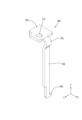
図4に示されるように、左出力バスバー26Lは、全体として上下方向(延び方向の一例)に細長く延びる板状をなしている。左出力バスバー26Lは、上下方向に細長く延びる板状をなす電極接続部34Lを有する。電極接続部34Lには、スリット25に後方から挿通されたリード端子24が、絶縁プロテクタ14の前方の領域において、電気的に接続されている。電極接続部34Lとリード端子24とは、溶接、半田付け、ろう付け等の公知の手法により接続される。本実施形態においては、電極接続部34Lとリード端子24とは、レーザー溶接により接続されている。
図3に示されるように、右出力バスバー26Rは、全体として上下方向に細長く延びる板状をなしている。右出力バスバー26Rは、上下方向に細長く延びる板状をなす電極接続部34Rを有する。図1に示されるように、電極接続部34Rには、スリット25に後方から挿通されたリード端子24が、絶縁プロテクタ14の前方の領域において、電気的に接続されている。電極接続部34Rとリード端子24とは、溶接、半田付け、ろう付け等の公知の手法により接続される。本実施形態においては、電極接続部34Rとリード端子24とは、レーザー溶接により接続されている。
図3に示されるように、接続バスバー26Cは、全体として上下方向に細長く延びる板状をなしている。左出力バスバー26Lは、上下方向に細長く延びる板状をなす電極接続部34Cを有する。図1に示されるように、電極接続部34Cには、スリット25に後方から挿通されたリード端子24が、絶縁プロテクタ14の前方の領域において、電気的に接続されている。電極接続部34Cとリード端子24とは、溶接、半田付け、ろう付け等の公知の手法により接続される。本実施形態においては、電極接続部34Cとリード端子24とは、レーザー溶接により接続されている。
図3に示されるように、絶縁プロテクタ14の前面には、フレキシブルプリント基板60(可撓性基板の一例)が配されている。フレキシブルプリント基板60は、絶縁性の合成樹脂からなるベースフィルム62(フィルムの一例)の片面、又は両面に、複数の導電路63が形成されてなる。詳細には図示しないが、ベースフィルム62、及び導電路63は、絶縁性の合成樹脂からなるカバーレイフィルムで覆われている。複数の導電路63は、銅や銅合金等の金属箔により形成されている(図5参照)。
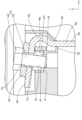
図5に示されるように、絶縁プロテクタ14には、被貫通部30Lの下方の位置に、台座部40Lが設けられている。台座部40Lは上方から見て略四角形状をなしている(図7参照)。図8に示されるように、台座部40Lの左右方向の長さ寸法は、2つの保護壁37Lの上端部同士の差し渡し寸法よりも小さく設定されている。台座部40Lの上方には、被貫通部30Lが配されるようになっている。
続いて、実施形態1の作用効果について説明する。まず、被貫通部30Lと、電極接続部34Lとが直交する場合について説明する。電極接続部34Lは、絶縁プロテクタ14に対して、上側挟持部38L、及び下側挟持部39Lによって位置決め状態で保持される。電極接続部34Lには蓄電素子12のリード端子24が接続されるようになっている。このため、電極接続部34Lと、絶縁プロテクタ14とは、比較的に高い精度で位置決めされるようになっている。
(1)複数の蓄電素子12は直列つなぎされていてもよいし、並列つなぎされていてもよい。
11: 蓄電モジュール
12: 蓄電素子
13: ケース
14: 絶縁プロテクタ
20: 開口部
21L: 挿通孔
23: ラミネートフィルム外装体
24: リード端子
25: スリット
26C: 接続バスバー
26R: 右出力バスバー
26L: 左出力バスバー
28C、28R、28L: 基板接続部
29: 固定孔
30R、30L: 被貫通部
31R、31L: 貫通孔
32: ボルト
33L: 出力端子
34C、34R、34L: 電極接続部
35: ナット
35R、35L: 曲がり部
36: ナット
37R、37L: 保護壁
38C、38R、38L: 上側挟持部
39C、39R、39L: 下側挟持部
40R、40L: 台座部
41R、41L: 収容部
42: ネジ孔
43: 軸部
44: 頭部
45: 後縁部
46: 前縁部
47: 右縁部
48: 左縁部
49: 後凹部
50: 前凹部
60: フレキシブルプリント基板
62: ベースフィルム
63: 導電路
64: 横行部
65: 上行部
66: ランド
67: 貫通孔
90: 出力用コネクタ
91: 端子
P1、P2: 間隔
P: 第1クリアランス
Q1、Q2: 間隔
Q: 第2クリアランス
Claims (5)
- 電極を有する複数の蓄電素子に取り付けられる配線モジュールであって、
絶縁性の合成樹脂からなる絶縁プロテクタと、
前記絶縁プロテクタに保持されると共に、前記電極に接続されるバスバーと、
前記バスバーを貫通する軸部と、前記軸部の端部に形成された頭部と、を有するボルトと、
前記ボルトの前記軸部に螺合するナットと、を備え、
前記バスバーは板状をなし、前記電極と接続されるとともに延び方向に沿って延びる電極接続部と、曲がり部によって前記電極接続部と接続され、前記延び方向と交差する第1方向に沿って延びるとともに前記ボルトの前記軸部が貫通する被貫通部と、を有し、
前記絶縁プロテクタは、前記電極接続部を位置決め状態で保持する保持部と、前記ナットまたは前記頭部の外形状よりも大きな内形状を有して前記ナットまたは前記頭部を収容する収容部と、を有し、
前記ナットまたは前記頭部が前記収容部に収容された状態で、前記第1方向について前記ナットまたは前記頭部と前記収容部との間に設けられた第1クリアランスは、前記延び方向と交差すると共に前記第1方向と異なる第2方向について前記ナットまたは前記頭部と前記収容部との間に設けられた第2クリアランスよりも大きく設定されている配線モジュール。 - 前記ボルトの前記軸部と前記ナットとが螺合した状態において、前記軸部の軸線が延びる方向は、前記電極接続部の延びる前記延び方向と交差している請求項1に記載の配線モジュール。
- 前記第1クリアランスの寸法は、前記第2クリアランスの寸法の2倍に設定されている請求項1または請求項2に記載の配線モジュール。
- 前記ボルトの前記軸部に前記ナットが螺合した状態で、前記ボルトの前記頭部と前記ナットとの間には、前記被貫通部と、外部回路と電気的に接続される出力端子とが挟まれている請求項1から請求項3のいずれか一項に記載の配線モジュール。
- 前記絶縁プロテクタには、可撓性を有するフィルムと前記フィルムに形成された導電路と、を有する可撓性基板が配されており、
前記バスバーは前記可撓性基板の前記導電路と接続される基板接続部を有し、
前記基板接続部が前記絶縁プロテクタに位置決め保持されている請求項1から請求項4のいずれか一項に記載の配線モジュール。
Applications Claiming Priority (3)
| Application Number | Priority Date | Filing Date | Title |
|---|---|---|---|
| JP2021066326 | 2021-04-09 | ||
| JP2021066326 | 2021-04-09 | ||
| PCT/JP2022/015353 WO2022215589A1 (ja) | 2021-04-09 | 2022-03-29 | 配線モジュール |
Publications (2)
| Publication Number | Publication Date |
|---|---|
| JPWO2022215589A1 JPWO2022215589A1 (ja) | 2022-10-13 |
| JP7637763B2 true JP7637763B2 (ja) | 2025-02-28 |
Family
ID=83545473
Family Applications (1)
| Application Number | Title | Priority Date | Filing Date |
|---|---|---|---|
| JP2023512957A Active JP7637763B2 (ja) | 2021-04-09 | 2022-03-29 | 配線モジュール |
Country Status (4)
| Country | Link |
|---|---|
| US (1) | US20240170797A1 (ja) |
| JP (1) | JP7637763B2 (ja) |
| CN (1) | CN117099255A (ja) |
| WO (1) | WO2022215589A1 (ja) |
Citations (4)
| Publication number | Priority date | Publication date | Assignee | Title |
|---|---|---|---|---|
| JP2016143466A (ja) | 2015-01-30 | 2016-08-08 | トヨタ自動車株式会社 | 電池及び組電池 |
| JP2019003737A (ja) | 2017-06-12 | 2019-01-10 | 株式会社オートネットワーク技術研究所 | 外部接続バスバー保持モジュール、接続モジュールおよび蓄電モジュール |
| JP2019133878A (ja) | 2018-02-01 | 2019-08-08 | トヨタ自動車株式会社 | 組電池 |
| WO2020171629A1 (ko) | 2019-02-21 | 2020-08-27 | 주식회사 엘지화학 | 유동 너트를 구비한 단자 연결구조를 갖는 전지 모듈과 이를 포함한 전지 팩 |
-
2022
- 2022-03-29 JP JP2023512957A patent/JP7637763B2/ja active Active
- 2022-03-29 WO PCT/JP2022/015353 patent/WO2022215589A1/ja not_active Ceased
- 2022-03-29 CN CN202280023344.7A patent/CN117099255A/zh active Pending
- 2022-03-29 US US18/282,887 patent/US20240170797A1/en active Pending
Patent Citations (4)
| Publication number | Priority date | Publication date | Assignee | Title |
|---|---|---|---|---|
| JP2016143466A (ja) | 2015-01-30 | 2016-08-08 | トヨタ自動車株式会社 | 電池及び組電池 |
| JP2019003737A (ja) | 2017-06-12 | 2019-01-10 | 株式会社オートネットワーク技術研究所 | 外部接続バスバー保持モジュール、接続モジュールおよび蓄電モジュール |
| JP2019133878A (ja) | 2018-02-01 | 2019-08-08 | トヨタ自動車株式会社 | 組電池 |
| WO2020171629A1 (ko) | 2019-02-21 | 2020-08-27 | 주식회사 엘지화학 | 유동 너트를 구비한 단자 연결구조를 갖는 전지 모듈과 이를 포함한 전지 팩 |
Also Published As
| Publication number | Publication date |
|---|---|
| CN117099255A (zh) | 2023-11-21 |
| WO2022215589A1 (ja) | 2022-10-13 |
| JPWO2022215589A1 (ja) | 2022-10-13 |
| US20240170797A1 (en) | 2024-05-23 |
Similar Documents
| Publication | Publication Date | Title |
|---|---|---|
| US11128018B2 (en) | Circuit body and battery module | |
| JP6256326B2 (ja) | 検知モジュール | |
| EP1054461B1 (en) | Battery connection plate and a manufacturing method therefor | |
| JP6717788B2 (ja) | 導体モジュール | |
| JP2012226969A (ja) | 電池モジュールのハーネス及び電池モジュール | |
| CN109075308B (zh) | 连接模块 | |
| CN112805872B (zh) | 柔性印制电路板、布线部件、蓄电模块以及连接模块 | |
| WO2013069756A1 (ja) | 配線モジュール | |
| JP6790923B2 (ja) | 接続モジュール | |
| JP7768439B2 (ja) | 配線モジュール | |
| US20230282945A1 (en) | Battery wiring module | |
| JP7637763B2 (ja) | 配線モジュール | |
| US20170164488A1 (en) | Electrical junction box | |
| JP7574652B2 (ja) | 外部接続バスバーおよび配線モジュール | |
| US9419358B2 (en) | Electrical connection device, assembly including such a device and an electronic board, and method for electrically connecting an electronic board | |
| JP7590130B2 (ja) | 配線モジュール | |
| WO2021075165A1 (ja) | 配線モジュール | |
| US10468200B2 (en) | Power supply device | |
| JP7516890B2 (ja) | 配線モジュール | |
| JP7538780B2 (ja) | 端子付キャパシタ及びキャパシタ内蔵コネクタ | |
| US20260031464A1 (en) | Battery module | |
| CN121753196A (zh) | 汇流条及布线模块 | |
| JP2012256524A (ja) | コネクタ |
Legal Events
| Date | Code | Title | Description |
|---|---|---|---|
| A621 | Written request for application examination |
Free format text: JAPANESE INTERMEDIATE CODE: A621 Effective date: 20230613 |
|
| A131 | Notification of reasons for refusal |
Free format text: JAPANESE INTERMEDIATE CODE: A131 Effective date: 20240827 |
|
| A521 | Request for written amendment filed |
Free format text: JAPANESE INTERMEDIATE CODE: A523 Effective date: 20241007 |
|
| TRDD | Decision of grant or rejection written | ||
| A01 | Written decision to grant a patent or to grant a registration (utility model) |
Free format text: JAPANESE INTERMEDIATE CODE: A01 Effective date: 20250128 |
|
| A61 | First payment of annual fees (during grant procedure) |
Free format text: JAPANESE INTERMEDIATE CODE: A61 Effective date: 20250217 |
|
| R150 | Certificate of patent or registration of utility model |
Ref document number: 7637763 Country of ref document: JP Free format text: JAPANESE INTERMEDIATE CODE: R150 |