JP7664421B2 - 三次元の蛇行経路の流路を有するボール制御バルブ - Google Patents
三次元の蛇行経路の流路を有するボール制御バルブ Download PDFInfo
- Publication number
- JP7664421B2 JP7664421B2 JP2023568302A JP2023568302A JP7664421B2 JP 7664421 B2 JP7664421 B2 JP 7664421B2 JP 2023568302 A JP2023568302 A JP 2023568302A JP 2023568302 A JP2023568302 A JP 2023568302A JP 7664421 B2 JP7664421 B2 JP 7664421B2
- Authority
- JP
- Japan
- Prior art keywords
- flow
- valve body
- fluid
- flow control
- control passages
- Prior art date
- Legal status (The legal status is an assumption and is not a legal conclusion. Google has not performed a legal analysis and makes no representation as to the accuracy of the status listed.)
- Active
Links
Images


Classifications
-
- F—MECHANICAL ENGINEERING; LIGHTING; HEATING; WEAPONS; BLASTING
- F16—ENGINEERING ELEMENTS AND UNITS; GENERAL MEASURES FOR PRODUCING AND MAINTAINING EFFECTIVE FUNCTIONING OF MACHINES OR INSTALLATIONS; THERMAL INSULATION IN GENERAL
- F16K—VALVES; TAPS; COCKS; ACTUATING-FLOATS; DEVICES FOR VENTING OR AERATING
- F16K47/00—Means in valves for absorbing fluid energy
- F16K47/04—Means in valves for absorbing fluid energy for decreasing pressure or noise level, the throttle being incorporated in the closure member
- F16K47/045—Means in valves for absorbing fluid energy for decreasing pressure or noise level, the throttle being incorporated in the closure member and the closure member being rotatable
-
- F—MECHANICAL ENGINEERING; LIGHTING; HEATING; WEAPONS; BLASTING
- F16—ENGINEERING ELEMENTS AND UNITS; GENERAL MEASURES FOR PRODUCING AND MAINTAINING EFFECTIVE FUNCTIONING OF MACHINES OR INSTALLATIONS; THERMAL INSULATION IN GENERAL
- F16K—VALVES; TAPS; COCKS; ACTUATING-FLOATS; DEVICES FOR VENTING OR AERATING
- F16K5/00—Plug valves; Taps or cocks comprising only cut-off apparatus having at least one of the sealing faces shaped as a more or less complete surface of a solid of revolution, the opening and closing movement being predominantly rotary
- F16K5/06—Plug valves; Taps or cocks comprising only cut-off apparatus having at least one of the sealing faces shaped as a more or less complete surface of a solid of revolution, the opening and closing movement being predominantly rotary with plugs having spherical surfaces; Packings therefor
-
- F—MECHANICAL ENGINEERING; LIGHTING; HEATING; WEAPONS; BLASTING
- F16—ENGINEERING ELEMENTS AND UNITS; GENERAL MEASURES FOR PRODUCING AND MAINTAINING EFFECTIVE FUNCTIONING OF MACHINES OR INSTALLATIONS; THERMAL INSULATION IN GENERAL
- F16K—VALVES; TAPS; COCKS; ACTUATING-FLOATS; DEVICES FOR VENTING OR AERATING
- F16K1/00—Lift valves or globe valves, i.e. cut-off apparatus with closure members having at least a component of their opening and closing motion perpendicular to the closing faces
- F16K1/16—Lift valves or globe valves, i.e. cut-off apparatus with closure members having at least a component of their opening and closing motion perpendicular to the closing faces with pivoted closure-members
- F16K1/18—Lift valves or globe valves, i.e. cut-off apparatus with closure members having at least a component of their opening and closing motion perpendicular to the closing faces with pivoted closure-members with pivoted discs or flaps
- F16K1/22—Lift valves or globe valves, i.e. cut-off apparatus with closure members having at least a component of their opening and closing motion perpendicular to the closing faces with pivoted closure-members with pivoted discs or flaps with axis of rotation crossing the valve member, e.g. butterfly valves
- F16K1/222—Shaping of the valve member
-
- F—MECHANICAL ENGINEERING; LIGHTING; HEATING; WEAPONS; BLASTING
- F16—ENGINEERING ELEMENTS AND UNITS; GENERAL MEASURES FOR PRODUCING AND MAINTAINING EFFECTIVE FUNCTIONING OF MACHINES OR INSTALLATIONS; THERMAL INSULATION IN GENERAL
- F16K—VALVES; TAPS; COCKS; ACTUATING-FLOATS; DEVICES FOR VENTING OR AERATING
- F16K47/00—Means in valves for absorbing fluid energy
- F16K47/04—Means in valves for absorbing fluid energy for decreasing pressure or noise level, the throttle being incorporated in the closure member
-
- F—MECHANICAL ENGINEERING; LIGHTING; HEATING; WEAPONS; BLASTING
- F16—ENGINEERING ELEMENTS AND UNITS; GENERAL MEASURES FOR PRODUCING AND MAINTAINING EFFECTIVE FUNCTIONING OF MACHINES OR INSTALLATIONS; THERMAL INSULATION IN GENERAL
- F16K—VALVES; TAPS; COCKS; ACTUATING-FLOATS; DEVICES FOR VENTING OR AERATING
- F16K5/00—Plug valves; Taps or cocks comprising only cut-off apparatus having at least one of the sealing faces shaped as a more or less complete surface of a solid of revolution, the opening and closing movement being predominantly rotary
- F16K5/06—Plug valves; Taps or cocks comprising only cut-off apparatus having at least one of the sealing faces shaped as a more or less complete surface of a solid of revolution, the opening and closing movement being predominantly rotary with plugs having spherical surfaces; Packings therefor
- F16K5/0605—Plug valves; Taps or cocks comprising only cut-off apparatus having at least one of the sealing faces shaped as a more or less complete surface of a solid of revolution, the opening and closing movement being predominantly rotary with plugs having spherical surfaces; Packings therefor with particular plug arrangements, e.g. particular shape or built-in means
-
- F—MECHANICAL ENGINEERING; LIGHTING; HEATING; WEAPONS; BLASTING
- F16—ENGINEERING ELEMENTS AND UNITS; GENERAL MEASURES FOR PRODUCING AND MAINTAINING EFFECTIVE FUNCTIONING OF MACHINES OR INSTALLATIONS; THERMAL INSULATION IN GENERAL
- F16K—VALVES; TAPS; COCKS; ACTUATING-FLOATS; DEVICES FOR VENTING OR AERATING
- F16K5/00—Plug valves; Taps or cocks comprising only cut-off apparatus having at least one of the sealing faces shaped as a more or less complete surface of a solid of revolution, the opening and closing movement being predominantly rotary
- F16K5/08—Details
- F16K5/14—Special arrangements for separating the sealing faces or for pressing them together
- F16K5/20—Special arrangements for separating the sealing faces or for pressing them together for plugs with spherical surfaces
Landscapes
- Engineering & Computer Science (AREA)
- General Engineering & Computer Science (AREA)
- Mechanical Engineering (AREA)
- Taps Or Cocks (AREA)
- Multiple-Way Valves (AREA)
- Details Of Valves (AREA)
- Sliding Valves (AREA)
Description
前記複数の流れ制御通路の各々は、前記流れ開口部と流体連通してよい。これに代えて、前記複数の流れ制御通路の各々は、前記流れ開口部から流体的に隔離してよい。前記バルブ本体は、一対の前記複数の流れ制御通路を流体的に接続するプレナムも備えてよい。
前記バルブ本体は、前記閉鎖位置、前記制限流れ位置、および前記自由流れ位置の間において、回転軸の周りを回転可能であってよく、前記流れ開口部は前記回転軸に対しほぼ垂直な流れ開口部軸に沿って延びている。
添付の図面に関連して以下に記載される詳細な説明は、流れ制御バルブの特定の実施形態の記載として意図されており、開発または利用され得る唯一の形態を表すことは意図されていない。本記載は、示される実施形態に関連して様々な構造および/または機能を説明するが、同一または同等の構造および/または機能が、本開示の範囲内に包含されることも意図される異なる実施形態によって達成され得ることが理解される。第1および第2などの関係語の使用は、そうしたエンティティ間の任意の実際のそうした関係または順序を必ずしも必要とするまたは暗示することなく、1つのエンティティを別のエンティティから区別するために使用されるに過ぎないことがさらに理解される。
制限流れ軸32および自由流れ軸24の両方は、回転軸26に垂直な共通の平面に存在してよい。さらに、制限流れ軸32および自由流れ軸24は、互いに交差してよく、互いから約45度だけ互いから角度がずれていてよいが、30~60度などの他の角度のずれが、本開示の趣旨および範囲から逸脱することなく、制限流れ軸32および自由流れ軸24によって画定されてよい。
一対の制限流れ領域136は、互いにほぼ直径方向に対向する関係により配置されてよい。各制限流れ領域136は、互いにほぼ平行に延びる複数の流れ制御通路112を備えてよい。所与の制限流れ領域136内の流れ制御通路112は、一連の径方向アレイに配置されてよく、各アレイは、流れ開口部114の中心軸140から異なる量だけ離間される。図5~図6に示される実施形態では、各制限流れ領域136は4つのアレイを備える。図5(バルブ本体110の下半分のみを示し、上半分は下半分の鏡像である)に示される視点から、外側から内側方向に移動すると、アレイは、第1のアレイ142(流れ開口部114から最も遠い)、第2のアレイ144、第3のアレイ146、および第4のアレイ148(流れ開口部114に最も近い)を備えてよい。第1のアレイ142は、5つの流れ制御通路112(その下半分が図5に示されている)を備えてよい。第2のアレイ144は、11個の流れ制御通路112を備えてよい。第3および第4のアレイ146、148は、各々、13個の流れ制御通路112を備えてよい。アレイ142~148の数および各アレイ142~148における通路112の数は、一例として提供されており、本開示を限定することを意図していない。この点に関して、バルブ本体110は、本開示の趣旨および範囲から逸脱することなく、異なる数のアレイ142~148、および各アレイ142~148内の異なる数の通路112を備えてよいことが企図される。
バルブ本体110が閉鎖位置にあるとき、閉鎖領域134は、バルブハウジングを通る流体の流れを防止するために、バルブハウジングの流体入口および流体出口と整合する。閉鎖位置では、制限流れ領域136および自由流れ領域138は、流体入口および流体出口からずれており、したがって、流体入口から流体を受け入れない。
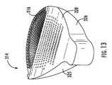
一対の制限流れ領域は、互いにほぼ直径方向に対向する関係により配置されてよい。各制限流れ領域は、複数の流れ制御通路212を備えてよく、これらは、一連の径方向アレイに配置されてよく、各々は、流れ開口部214の中心軸232(例えば、自由流れ軸)から異なる量だけ離間している。図7に示される実施形態では、各制限流れ領域は5つのアレイを備え、これらのアレイは、外側から内側方向に移動して、第1のアレイ234(流れ開口部214から最も遠い)、第2のアレイ236、第3のアレイ238、第4のアレイ240、および第5のアレイ242(流れ開口部214に最も近い)を備えてよい。アレイ234~242の各々は、11個の流れ制御通路212を備える。アレイ234~242の数および各アレイ234~242における通路212の数は、一例として提供されており、本開示を限定することを意図していない。この点に関して、バルブ本体210は、本開示の趣旨および範囲から逸脱することなく、異なる数のアレイ234~242、および各アレイ234~242内の異なる数の通路212を備えてよいことが企図される。
バルブ本体210が閉鎖位置にあるとき、閉鎖領域は、バルブハウジングを通る流体の流れを防止するために、バルブハウジングの流体入口および流体出口と整合する。閉鎖位置では、制限流れ領域および自由流れ領域は、流体入口および流体出口からずれている。
バルブ本体410が閉鎖位置にあるとき、閉鎖領域は、バルブハウジングを通る流体の流れを防止するために、バルブハウジングの流体入口および流体出口と整合する。閉鎖位置では、制限流れ領域および自由流れ領域の両方が、流体入口および流体出口からずれている。
ここで図25~図27を参照すると、図22~図24に示されるバルブ本体410の変形形態であるバルブ本体450が示されている。この点に関して、バルブ本体410と450との間の主な違いは、バルブ本体450に流れ開口部、すなわち上記の流れ開口部414がないことにある。むしろ、バルブ本体450を通る唯一の流路は、流れ制御通路452を介する。これらのラインに沿って、バルブ本体450に追加の流れ制御通路452があってよく、そうでなければそのエリアは流れ開口部414を備える。
ボール型バルブ本体を備えるバルブを通じた徐々の流量制御の使用に関するさらなる詳細は、「ボール制御バルブ用の三次元蛇行経路流れ要素“Three-Dimensional Tortuous Path Flow Element For Ball Control Valves”」と題される米国特許出願第16/737,594号に見られ、その内容も参照により本明細書に明示的に組み込まれる。
Claims (26)
- 流体入口および流体出口を有するバルブハウジングにおける使用のためのバルブ本体であって、
球形の構成である外面と、
前記外面の片側から前記外面の反対側まで直径方向に延びる流れ開口部であって、自由流れ軸に同軸整合している流れ開口部と、
前記外面に外面開口部を各々有する、複数の流れ制御通路であって、前記複数の流れ制御通路のうちの1つ以上は蛇行構成である1つ以上のセグメントを有する、複数の流れ制御通路と、を備え、
前記バルブ本体は、閉鎖位置、制限流れ位置、および自由流れ位置の間において前記バルブハウジングに対し移動可能であり、
前記閉鎖位置では、前記流れ開口部と前記複数の流れ制御通路のすべてとが、前記流体入口および前記流体出口の間における流体の流れを防止するように、前記流体入口および前記流体出口の両方との整合から外れており、
前記制限流れ位置では、前記流体入口および前記流体出口の間の流体連通を可能とするように、前記複数の流れ制御通路の1つ以上が移動して前記流体入口および前記流体出口と流体連通し、
前記自由流れ位置では、前記流体入口および前記流体出口の間の流体連通を可能とするように、前記流れ開口部が移動して前記流体入口および前記流体出口と流体連通する、バルブ本体。 - 前記バルブ本体の少なくとも一部は、3次元プリントにより形成されている、請求項1に記載のバルブ本体。
- 前記バルブ本体の全体は、3次元プリントにより形成されている、請求項1に記載のバルブ本体。
- 前記複数の流れ制御通路の各々は、前記流れ開口部と流体連通している、請求項1に記載のバルブ本体。
- 前記複数の流れ制御通路の各々は、前記流れ開口部から流体的に隔離している、請求項1に記載のバルブ本体。
- 一対の前記複数の流れ制御通路を流体的に接続するプレナムをさらに備える、請求項5に記載のバルブ本体。
- 前記バルブ本体は、前記バルブハウジングに対する前記バルブ本体の90度以下の大きさの回転により、前記閉鎖位置から前記制限流れ位置に、また前記自由流れ位置に移行するように構成されている、請求項1に記載のバルブ本体。
- 各外面開口部は同様の構成である、請求項1に記載のバルブ本体。
- 前記1つ以上の外面開口部は、第1の構成であり、1つ以上の外面開口部は、前記第1の構成とは異なる第2の構成である、請求項1に記載のバルブ本体。
- 前記外面開口部は、複数のアレイに配置されている、請求項1に記載のバルブ本体。
- 前記バルブ本体は、前記閉鎖位置、前記制限流れ位置、および前記自由流れ位置の間において、回転軸の周りを回転可能であり、前記流れ開口部は前記回転軸に対しほぼ垂直な流れ開口部軸に沿って延びている、請求項1に記載のバルブ本体。
- 流体入口および流体出口を有するバルブハウジングにおける使用のためのバルブ本体であって、
球形の構成である外面を備え、前記外面は、閉鎖領域、一対の制限領域、および一対の自由流れ領域を備え、前記閉鎖領域は、開口部が形成されていない連続表面を備え、各制限領域は、各々が内部通路と連通している複数の通路開口部を備え、各自由流れ領域は、共通の自由流れ開口部と連通しており、複数の内部通路のうちの1つ以上は蛇行構成である1つ以上のセグメントを有し、
前記バルブ本体は、閉鎖位置、制限流れ位置、および自由流れ位置の間において前記バルブハウジングに対し移動可能であり、
前記閉鎖位置では、前記閉鎖領域は少なくとも前記流体入口と整合しており、前記一対の制限領域および前記一対の自由流れ領域は、前記流体入口および前記流体出口の間における流体の流れを防止するように、前記流体入口との整合から外れており、
前記制限流れ位置では、前記流体入口および前記流体出口の間の流体連通を可能とするように、前記複数の制限領域の各々の少なくとも一部が移動して前記流体入口および前記流体出口と流体連通し、
前記自由流れ位置では、前記流体入口および前記流体出口の間の流体連通を可能とするように、前記一対の自由流れ領域が移動して前記流体入口および前記流体出口と流体連通する、バルブ本体。 - 前記バルブ本体の少なくとも一部は、3次元プリントにより形成されている、請求項12に記載のバルブ本体。
- 前記複数の内部通路の各々は、前記流れ開口部と流体連通している、請求項12に記載のバルブ本体。
- 前記複数の内部通路の各々は、前記流れ開口部から流体的に隔離している、請求項12に記載のバルブ本体。
- 前記バルブ本体は、前記バルブハウジングに対する前記バルブ本体の90度以下の大きさの回転により、前記閉鎖位置から前記制限流れ位置に、また前記自由流れ位置に移行するように構成されている、請求項12に記載のバルブ本体。
- 各通路開口部は同様の構成である、請求項12に記載のバルブ本体。
- 前記1つ以上の通路開口部は、第1の構成であり、1つ以上の通路開口部は、前記第1の構成とは異なる第2の構成である、請求項12に記載のバルブ本体。
- 前記通路開口部は、複数のアレイに配置されている、請求項12に記載のバルブ本体。
- 前記バルブ本体は、前記閉鎖位置、前記制限流れ位置、および前記自由流れ位置の間において、回転軸の周りを回転可能であり、前記流れ開口部は前記回転軸に対しほぼ垂直な流れ開口部軸に沿って延びている、請求項12に記載のバルブ本体。
- 前記複数の流れ制御通路の各々は蛇行構成である1つ以上のセグメントを有する、請求項1に記載のバルブ本体。
- 前記複数の流れ制御通路のうちの2つ以上は蛇行構成であるセグメントを各々有し、各セグメントは異なる長さである、請求項1に記載のバルブ本体。
- 前記複数の流れ制御通路の少なくとも一部は制限流れ軸に平行であり、前記制限流れ軸は前記自由流れ軸から角度がずれている、請求項1に記載のバルブ本体。
- 前記一対の前記複数の流れ制御通路のうちの1つ以上は蛇行構成である1つ以上のセグメントを有する、請求項6に記載のバルブ本体。
- 前記一対の前記複数の流れ制御通路の両方は蛇行構成である1つ以上のセグメントを有する、請求項6に記載のバルブ本体。
- 流体入口および流体出口を有するバルブハウジングにおける使用のためのバルブ本体であって、
部分的に球形である外側シェルと、
外面を有する内側制限コアと、
前記内側制限コアによって少なくとも部分的には画定される貫流チャネルと、
複数の流れ制御通路と、を備え、各流れ制御通路は、前記内側制限コアの前記外面に外面開口部を有し、
前記外側シェルは、前記内側制限コアの前記外面の一部を順次露出させるように、前記バルブハウジングに対し閉鎖位置と開放位置との間において移動可能であり、
前記内側制限コアは、前記バルブハウジングに対し制限位置と非制限位置との間において移動可能であり、
前記制限位置では、前記流体入口および前記流体出口の間の流体連通を可能とするように、前記内側制限コアの前記外面の前記一部における前記複数の流れ制御通路の一部が移動して前記流体入口および前記流体出口と流体連通し、
前記非制限位置では、前記流体入口および前記流体出口の間の流体連通を可能とするように、前記貫流チャネルは移動して前記流体入口および前記流体出口と流体連通し、
前記外側シェルおよび前記内側制限コアは、前記バルブハウジング内において各々独立して移動可能である、バルブ本体。
Applications Claiming Priority (5)
| Application Number | Priority Date | Filing Date | Title |
|---|---|---|---|
| US202163185813P | 2021-05-07 | 2021-05-07 | |
| US63/185,813 | 2021-05-07 | ||
| US17/731,800 US11906076B2 (en) | 2021-05-07 | 2022-04-28 | Ball control valves having three-dimensional tortuous path flowpaths |
| US17/731,800 | 2022-04-28 | ||
| PCT/US2022/027326 WO2022235582A1 (en) | 2021-05-07 | 2022-05-02 | Ball control valves having three-dimensional tortuous path flowpaths |
Publications (2)
| Publication Number | Publication Date |
|---|---|
| JP2024519530A JP2024519530A (ja) | 2024-05-15 |
| JP7664421B2 true JP7664421B2 (ja) | 2025-04-17 |
Family
ID=83901313
Family Applications (1)
| Application Number | Title | Priority Date | Filing Date |
|---|---|---|---|
| JP2023568302A Active JP7664421B2 (ja) | 2021-05-07 | 2022-05-02 | 三次元の蛇行経路の流路を有するボール制御バルブ |
Country Status (8)
| Country | Link |
|---|---|
| US (1) | US11906076B2 (ja) |
| EP (1) | EP4334611A4 (ja) |
| JP (1) | JP7664421B2 (ja) |
| AU (1) | AU2022271196B2 (ja) |
| BR (1) | BR112023023159A2 (ja) |
| CA (1) | CA3217968A1 (ja) |
| TW (1) | TWI836418B (ja) |
| WO (1) | WO2022235582A1 (ja) |
Families Citing this family (3)
| Publication number | Priority date | Publication date | Assignee | Title |
|---|---|---|---|---|
| US11906076B2 (en) * | 2021-05-07 | 2024-02-20 | Control Components, Inc. | Ball control valves having three-dimensional tortuous path flowpaths |
| WO2023214109A1 (en) * | 2022-05-02 | 2023-11-09 | Neles Finland Oy | Valve and method for manufacturing a closure member |
| AU2023316578A1 (en) * | 2022-07-26 | 2025-02-13 | Bray International, Inc. | Low noise and anti-cavitation rotary control valve |
Citations (2)
| Publication number | Priority date | Publication date | Assignee | Title |
|---|---|---|---|---|
| CN103148236A (zh) | 2013-03-20 | 2013-06-12 | 陈曙光 | 一种转弯调节球阀 |
| US20190107227A1 (en) | 2017-10-10 | 2019-04-11 | Metso Flow Control Oy | Valve and closure member |
Family Cites Families (28)
| Publication number | Priority date | Publication date | Assignee | Title |
|---|---|---|---|---|
| USRE31105E (en) | 1974-02-21 | 1982-12-21 | Controlled pressure drop valve | |
| US4295493A (en) | 1979-04-02 | 1981-10-20 | The Babcock & Wilcox Company | Drag ball valve including variable pressure reducing means |
| US4212321A (en) * | 1979-04-09 | 1980-07-15 | J. R. Butler | Low noise rotary control valve |
| DE3017857C2 (de) * | 1980-05-09 | 1985-10-10 | Hulsey, Eldon Scott | Hahn mit Dämpfungsvorrichtung |
| FR2506420A1 (fr) * | 1981-05-22 | 1982-11-26 | Alsthom Atlantique | Vanne a boisseau avec attenuateur de turbulence |
| FI79184C (fi) | 1988-01-04 | 1989-11-10 | Neles Oy | Staengningsorgan i ventil. |
| US5070909A (en) * | 1990-06-11 | 1991-12-10 | Davenport Robert G | Low recovery rotary control valve |
| US5332004A (en) | 1991-08-30 | 1994-07-26 | Fisher Controls International, Inc. | Rotary noise attenuator |
| US5218984A (en) | 1992-05-29 | 1993-06-15 | Allen Ernest E | Means and method for noise and cavitation attenuation in ball-type valves |
| FR2693248B1 (fr) * | 1992-07-03 | 1994-09-23 | Roger Bey | Vanne du type à bille ou à boisseau équipé d'un insert. |
| US5287889A (en) * | 1992-09-22 | 1994-02-22 | Leinen Christopher M | Low-noise rotary control valve |
| US5524863A (en) * | 1994-06-08 | 1996-06-11 | Daniel Industries, Inc. | Quarter turn rotatable flow control valve |
| US5937901A (en) | 1995-12-22 | 1999-08-17 | Rotatrol Ag | Rotary noise attenuating valve |
| US5680889A (en) | 1996-09-23 | 1997-10-28 | Dresser Industries, Inc. | Low noise ball valve assembly |
| US5771929A (en) * | 1996-10-24 | 1998-06-30 | Dresser Industries, Inc. | Low noise ball valve assembly with airfoil insert |
| US5890505A (en) | 1997-04-03 | 1999-04-06 | Dresser Industries, Inc. | Low noise ball valve assembly with downstream airfoil insert |
| JPH11325271A (ja) * | 1998-05-08 | 1999-11-26 | Hirano Seiki Kogyo Kk | 弁 |
| US6868865B2 (en) * | 2002-04-12 | 2005-03-22 | Control Components, Inc. | Rotary drag valve |
| ITMI20030889A1 (it) | 2003-04-30 | 2004-11-01 | Pibiviesse S P A | Valvola di regolazione |
| US7178782B1 (en) | 2003-05-23 | 2007-02-20 | The United States Of America As Represented By The Secretary Of The Navy | Quiet opening ball valve |
| US6974116B1 (en) * | 2004-06-23 | 2005-12-13 | Evola Limited | Rotary ball valve assembly |
| US7156122B2 (en) * | 2005-04-22 | 2007-01-02 | Mogas Industries, Inc. | Rotary ball valve assembly |
| EP2628983A3 (en) | 2007-12-07 | 2013-10-02 | Mogas Industries Incorporated | Ball valve impedance seat |
| US8826938B2 (en) | 2008-01-22 | 2014-09-09 | Control Components, Inc. | Direct metal laser sintered flow control element |
| US8141843B2 (en) | 2008-12-31 | 2012-03-27 | Dresser, Inc. | Fluid control valve |
| US9528632B2 (en) | 2014-10-14 | 2016-12-27 | General Electric Company | Tortuous path control valve trim |
| US10704709B2 (en) * | 2017-04-04 | 2020-07-07 | Schaeffler Technologies AG & Co. KG | Variations of fluid opening geometry for rotary valve body |
| US11906076B2 (en) * | 2021-05-07 | 2024-02-20 | Control Components, Inc. | Ball control valves having three-dimensional tortuous path flowpaths |
-
2022
- 2022-04-28 US US17/731,800 patent/US11906076B2/en active Active
- 2022-05-02 JP JP2023568302A patent/JP7664421B2/ja active Active
- 2022-05-02 BR BR112023023159A patent/BR112023023159A2/pt unknown
- 2022-05-02 EP EP22799375.5A patent/EP4334611A4/en active Pending
- 2022-05-02 WO PCT/US2022/027326 patent/WO2022235582A1/en not_active Ceased
- 2022-05-02 AU AU2022271196A patent/AU2022271196B2/en active Active
- 2022-05-02 CA CA3217968A patent/CA3217968A1/en active Pending
- 2022-05-06 TW TW111117070A patent/TWI836418B/zh active
Patent Citations (2)
| Publication number | Priority date | Publication date | Assignee | Title |
|---|---|---|---|---|
| CN103148236A (zh) | 2013-03-20 | 2013-06-12 | 陈曙光 | 一种转弯调节球阀 |
| US20190107227A1 (en) | 2017-10-10 | 2019-04-11 | Metso Flow Control Oy | Valve and closure member |
Also Published As
| Publication number | Publication date |
|---|---|
| US11906076B2 (en) | 2024-02-20 |
| US20220356951A1 (en) | 2022-11-10 |
| CA3217968A1 (en) | 2022-11-10 |
| EP4334611A4 (en) | 2025-07-09 |
| AU2022271196A1 (en) | 2023-11-23 |
| WO2022235582A1 (en) | 2022-11-10 |
| EP4334611A1 (en) | 2024-03-13 |
| JP2024519530A (ja) | 2024-05-15 |
| TW202311652A (zh) | 2023-03-16 |
| TWI836418B (zh) | 2024-03-21 |
| AU2022271196B2 (en) | 2025-12-11 |
| BR112023023159A2 (pt) | 2024-01-23 |
Similar Documents
| Publication | Publication Date | Title |
|---|---|---|
| JP7664421B2 (ja) | 三次元の蛇行経路の流路を有するボール制御バルブ | |
| US10690253B2 (en) | Multi-stage, multi-path rotary disc | |
| US12398826B2 (en) | Three-dimensional tortuous path flow element for ball control valves | |
| EP1593887B1 (en) | Flow rate control valve | |
| JP5759647B1 (ja) | 二重偏心弁 | |
| EP2691675B1 (en) | Valve with dual rotation valve member | |
| CN111720591B (zh) | 分配阀和制冷系统 | |
| JP7685627B2 (ja) | マルチレベルの回転プラグ弁 | |
| CA2708254A1 (en) | Ball valve impedance seat | |
| CN115485493A (zh) | 阀装置 | |
| US20200284357A1 (en) | Eccentric rotary valve | |
| KR102034415B1 (ko) | 유량제어용 버터플라이 밸브 | |
| US11092249B2 (en) | Binary mode fluid valve | |
| JP4086495B2 (ja) | 定流量充水機能を備えたバタフライ弁 | |
| WO2005036036A1 (ja) | 二方ボール弁 |
Legal Events
| Date | Code | Title | Description |
|---|---|---|---|
| A529 | Written submission of copy of amendment under article 34 pct |
Free format text: JAPANESE INTERMEDIATE CODE: A529 Effective date: 20240109 |
|
| A621 | Written request for application examination |
Free format text: JAPANESE INTERMEDIATE CODE: A621 Effective date: 20240109 |
|
| A131 | Notification of reasons for refusal |
Free format text: JAPANESE INTERMEDIATE CODE: A131 Effective date: 20241203 |
|
| A977 | Report on retrieval |
Free format text: JAPANESE INTERMEDIATE CODE: A971007 Effective date: 20241211 |
|
| TRDD | Decision of grant or rejection written | ||
| A01 | Written decision to grant a patent or to grant a registration (utility model) |
Free format text: JAPANESE INTERMEDIATE CODE: A01 Effective date: 20250311 |
|
| A61 | First payment of annual fees (during grant procedure) |
Free format text: JAPANESE INTERMEDIATE CODE: A61 Effective date: 20250407 |
|
| R150 | Certificate of patent or registration of utility model |
Ref document number: 7664421 Country of ref document: JP Free format text: JAPANESE INTERMEDIATE CODE: R150 |