KR20160090908A - 전력 생산 및/또는 열 공급용 증기 발생기의 출력을 제어하는 방법 - Google Patents
전력 생산 및/또는 열 공급용 증기 발생기의 출력을 제어하는 방법 Download PDFInfo
- Publication number
- KR20160090908A KR20160090908A KR1020167018541A KR20167018541A KR20160090908A KR 20160090908 A KR20160090908 A KR 20160090908A KR 1020167018541 A KR1020167018541 A KR 1020167018541A KR 20167018541 A KR20167018541 A KR 20167018541A KR 20160090908 A KR20160090908 A KR 20160090908A
- Authority
- KR
- South Korea
- Prior art keywords
- steam generator
- prediction
- output
- load
- cleaning
- Prior art date
- Legal status (The legal status is an assumption and is not a legal conclusion. Google has not performed a legal analysis and makes no representation as to the accuracy of the status listed.)
- Granted
Links
Images



Classifications
-
- F—MECHANICAL ENGINEERING; LIGHTING; HEATING; WEAPONS; BLASTING
- F22—STEAM GENERATION
- F22B—METHODS OF STEAM GENERATION; STEAM BOILERS
- F22B37/00—Component parts or details of steam boilers
- F22B37/02—Component parts or details of steam boilers applicable to more than one kind or type of steam boiler
- F22B37/56—Boiler cleaning control devices, e.g. for ascertaining proper duration of boiler blow-down
-
- F—MECHANICAL ENGINEERING; LIGHTING; HEATING; WEAPONS; BLASTING
- F23—COMBUSTION APPARATUS; COMBUSTION PROCESSES
- F23J—REMOVAL OR TREATMENT OF COMBUSTION PRODUCTS OR COMBUSTION RESIDUES; FLUES
- F23J3/00—Removing solid residues from passages or chambers beyond the fire, e.g. from flues by soot blowers
- F23J3/02—Cleaning furnace tubes; Cleaning flues or chimneys
- F23J3/023—Cleaning furnace tubes; Cleaning flues or chimneys cleaning the fireside of watertubes in boilers
-
- F—MECHANICAL ENGINEERING; LIGHTING; HEATING; WEAPONS; BLASTING
- F28—HEAT EXCHANGE IN GENERAL
- F28D—HEAT-EXCHANGE APPARATUS, NOT PROVIDED FOR IN ANOTHER SUBCLASS, IN WHICH THE HEAT-EXCHANGE MEDIA DO NOT COME INTO DIRECT CONTACT
- F28D1/00—Heat-exchange apparatus having stationary conduit assemblies for one heat-exchange medium only, the media being in contact with different sides of the conduit wall, in which the other heat-exchange medium is a large body of fluid, e.g. domestic or motor car radiators
- F28D1/02—Heat-exchange apparatus having stationary conduit assemblies for one heat-exchange medium only, the media being in contact with different sides of the conduit wall, in which the other heat-exchange medium is a large body of fluid, e.g. domestic or motor car radiators with heat-exchange conduits immersed in the body of fluid
- F28D1/04—Heat-exchange apparatus having stationary conduit assemblies for one heat-exchange medium only, the media being in contact with different sides of the conduit wall, in which the other heat-exchange medium is a large body of fluid, e.g. domestic or motor car radiators with heat-exchange conduits immersed in the body of fluid with tubular conduits
- F28D1/053—Heat-exchange apparatus having stationary conduit assemblies for one heat-exchange medium only, the media being in contact with different sides of the conduit wall, in which the other heat-exchange medium is a large body of fluid, e.g. domestic or motor car radiators with heat-exchange conduits immersed in the body of fluid with tubular conduits the conduits being straight
- F28D1/0535—Heat-exchange apparatus having stationary conduit assemblies for one heat-exchange medium only, the media being in contact with different sides of the conduit wall, in which the other heat-exchange medium is a large body of fluid, e.g. domestic or motor car radiators with heat-exchange conduits immersed in the body of fluid with tubular conduits the conduits being straight the conduits having a non-circular cross-section
- F28D1/05366—Assemblies of conduits connected to common headers, e.g. core type radiators
-
- F—MECHANICAL ENGINEERING; LIGHTING; HEATING; WEAPONS; BLASTING
- F28—HEAT EXCHANGE IN GENERAL
- F28G—CLEANING OF INTERNAL OR EXTERNAL SURFACES OF HEAT-EXCHANGE OR HEAT-TRANSFER CONDUITS, e.g. WATER TUBES OR BOILERS
- F28G15/00—Details
- F28G15/003—Control arrangements
-
- F—MECHANICAL ENGINEERING; LIGHTING; HEATING; WEAPONS; BLASTING
- F28—HEAT EXCHANGE IN GENERAL
- F28D—HEAT-EXCHANGE APPARATUS, NOT PROVIDED FOR IN ANOTHER SUBCLASS, IN WHICH THE HEAT-EXCHANGE MEDIA DO NOT COME INTO DIRECT CONTACT
- F28D21/00—Heat-exchange apparatus not covered by any of the groups F28D1/00 - F28D20/00
- F28D2021/0019—Other heat exchangers for particular applications; Heat exchange systems not otherwise provided for
- F28D2021/008—Other heat exchangers for particular applications; Heat exchange systems not otherwise provided for for vehicles
- F28D2021/0091—Radiators
- F28D2021/0094—Radiators for recooling the engine coolant
-
- F—MECHANICAL ENGINEERING; LIGHTING; HEATING; WEAPONS; BLASTING
- F28—HEAT EXCHANGE IN GENERAL
- F28F—DETAILS OF HEAT-EXCHANGE AND HEAT-TRANSFER APPARATUS, OF GENERAL APPLICATION
- F28F2225/00—Reinforcing means
- F28F2225/08—Reinforcing means for header boxes
Landscapes
- Engineering & Computer Science (AREA)
- Mechanical Engineering (AREA)
- General Engineering & Computer Science (AREA)
- Physics & Mathematics (AREA)
- Thermal Sciences (AREA)
- Chemical & Material Sciences (AREA)
- Combustion & Propulsion (AREA)
- Control Of Steam Boilers And Waste-Gas Boilers (AREA)
- Control Of Eletrric Generators (AREA)
Abstract
Description
도 1은 24시간의 기간에 걸친 증기 발생기의 출력 도표로서, 총출력으로서의 증기 발생기의 최대 가능 전기 출력, 총출력으로서의 발전기의 전기 출력, 순출력으로서의 증기 발생기의 전기 출력, 및 이후로 스케줄로 지칭될 해당 기간에 대한 제어 계획이 기입되어 있는 도표이고,
도 2는 증기 발생기의 제어 및 예측의 블록도이며,
도 3은 여러 날들에 걸친 제어 계획 또는 스케줄의 일례로서, 전기 출력이 시간 눈금을 따라 기입되어 있는 도표이고,
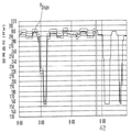
도 4는 16시간의 기간에 걸쳐 기입된 증기 발생기의 전기 출력을 나타낸 도표로서, 증기 발생기의 최대 가능 총출력, 세척에 필요한 출력 손실을 제외한 증기 발생기의 최대 가능 출력, 및 증기 발생기의 제어에 따라 실제로 나오는 총 발전기 출력이 표시되어 있는 도표이다.
PGB: 총 발전기 출력
PGN: 순 발전기 출력
PDispo: 제어 계획/스케줄
PMBR: 수트 블로워 이후의 증기 발생기의 최대 총출력
1: 발전소 블록 2: 전력 망
3: 발전소 제어 기법 4: 세척 장치
5: 가상 발전소 블록 6: 데이터베이스
7: 부하 제어기 8: 가용성 예측
9: 발전소 가동 계획 10: 부하 수요
11: 스케줄
Claims (17)
- 증기 발생기의 작동 중에 증기 및/또는 물로 작동되는 세척 장치를 사용하는 것을 감안하여 전력 생산 및/또는 열 공급용 증기 발생기의 출력을 제어하는 방법으로서,
- 증기 발생기의 가열 면의 유효성 및/또는 오염 상태에 대한 직간접적인 판정을 가능하게 하는 증기 발생기의 상태 변수들을 모니터링하는 것,
- 측정된 및/또는 파악된 상태 변수들을 기반으로 하여 유효성 예측을 수립하는 것,
- 전력 수요 및/또는 열 수요의 함수로서 부하 예측을 수립하는 것,
- 가용성 예측으로서 및 주위 온도 및/또는 연료 품질의 함수로서 증기 발생기의 예상 가용 최대 출력에 관한 예측을 수립하는 것, 및
- 유효성 예측의 함수로서 최적의 세척 시점을 결정하되, 증기 발생기의 가열 면의 소정의 최소 유효성을 하회하지 않을 것 및/또는 가열 면의 소정의 최대 허용 오염도를 초과하지 않을 것을 조건으로 유효성 예측에 따라 개시될 타깃 세척 과정을 부하 예측 및/또는 가용성 예측에 의존하여 변경하는 것을 포함하는 방법. - 제 1 항에 있어서, 유효성 예측에 따라 개시될 타깃 세척 과정을 연기 또는 억제 및/또는 단축 또는 연장 및/또는 증강 또는 감쇠시키는 것을 특징으로 하는 방법.
- 제 1 항 또는 제 2 항에 있어서, 상태 변수들로서 적어도 증기 발생기의 가열 면 온도 및/또는 재가열 온도를 파악 및/또는 측정하는 것을 특징으로 하는 방법.
- 선행 항들 중 어느 한 항에 있어서, 증기 발생기에 대한 부하 예측을 기상 예보 데이터의 함수로서 수립하는 것을 특징으로 하는 방법.
- 선행 항들 중 어느 한 항에 있어서, 강력한 부하가 예측될 경우에는 타깃 세척 과정을 억제 또는 연기 및/또는 감쇠 및/또는 단축시키고, 미약한 부하가 예측될 경우에는 타깃 세척 과정을 앞당김 및/또는 증강하는 것을 특징으로 하는 방법.
- 선행 항들 중 어느 한 항에 있어서, 지연된 타깃 세척 과정을 증강하는 것을 특징으로 하는 방법.
- 선행 항들 중 어느 한 항에 있어서, 부하 예측, 가용성 예측, 및 유효성 예측을 신경망 모델에 의해 수립하는 것을 특징으로 하는 방법.
- 제 7 항에 있어서, 적어도 유효성 예측과 부하 예측을 세척 과정을 제어하는 퍼지 제어기의 입력 변수로서 사용하는 것을 특징으로 하는 방법.
- 제 8 항에 있어서, 세척 과정의 지속 시간 및 세척 면적 크기에 의존하여 예상할 수 있는 세척에 기인한 가열 면의 마모를 퍼지 제어기의 입력 변수로서 사용하는 것을 특징으로 하는 방법.
- 제 8 항 또는 제 9 항에 있어서, 부하 예측을 전력 가격 예측으로서 나타내되, 바람직하게는 전력 가격 예측을 퍼지 제어기의 입력 변수로서 사용하는 것을 특징으로 하는 방법.
- 선행 항들 중 어느 한 항에 있어서, 강력한 부하의 단계 내에서 타깃 세척 과정을 증기 발생기의 가용성이 높은 것으로 예측된 시간으로 연기하는 것을 특징으로 하는 방법.
- 선행 항들 중 어느 한 항에 있어서, 부하 예측 및 가용성 예측에 의존하여 부하에 따라 제어되는 증기 발생기의 출력 제어를 위한 제어 계획을 수립하고, 증기 발생기를 제어 계획에 의거하여 출력 제어하는 것을 특징으로 하는 방법.
- 선행 항들 중 어느 한 항에 있어서, 부하 예측, 가용성 예측, 및 유효성 예측을 시간 및/또는 일별로 산정된 시간에 대해, 바람직하게는 약 0 내지 24시간 및/또는 약 0 내지 48시간에 대해 수립하는 것을 특징으로 하는 방법.
- 전력 생산 및 열 공급용 증기 발생기의 출력을 제어하되, 적어도 하나의 증기 발생기 및 제어 에너지 제공 시스템을 가상 밸런싱 그룹으로 통합하는 방법으로서,
- 증기 발생기 또는 증기 발생기들에 대한 전력 수요 및/또는 열 수요의 함수로서 부하 예측을 수립하는 것 및
- 증기 발생기 또는 증기 발생기들의 예상 가용 최대 출력에 대한 예측을 가용성 예측으로서 및 바람직하게는 주위 온도 및/또는 연료 품질의 함수로서 수립하는 것을 포함하되,
제어 계획이 밸런싱 그룹으로 통합되는 최대 출력을 갖는 증기 발생기와 최소 출력을 갖는 제어 에너지 제공 시스템을 감안하는 방법. - 제 14 항에 있어서, 증기 발생기 또는 증기 발생기들의 총 발전기 출력 및/또는 순 발전기 출력을 모니터링하고, 제어 에너지 제공 시스템이 제어 계획과 대비한 생산 차를 보상하도록 제어 에너지 제공 시스템을 제어하는 것을 특징으로 하는 방법.
- 제 14 항 또는 제 15 항에 있어서, 제어 에너지 제공 시스템으로서 차단 가능한 부하 및/또는 전력 생산 시스템, 특히 증기 발생기 또는 가스 발전소를 사용하는 것을 특징으로 하는 방법.
- 제 14 항 내지 제 16 항 중 어느 한 항에 있어서, 보충적 출력 옵션들 및/또는 제어 에너지 옵션들을 가용성 예측에서 감안하되, 바람직하게는 보충적 출력 옵션들이 개개의 출력 감소 구성 요소들의 일시적 차단을 기반으로 하는 것을 특징으로 하는 방법.
Applications Claiming Priority (1)
| Application Number | Priority Date | Filing Date | Title |
|---|---|---|---|
| PCT/EP2013/076142 WO2015086051A1 (de) | 2013-12-10 | 2013-12-10 | Verfahren zur leistungsregelung von dampferzeugern zur stromerzeugung und/oder wärmebereitstellung |
Publications (2)
| Publication Number | Publication Date |
|---|---|
| KR20160090908A true KR20160090908A (ko) | 2016-08-01 |
| KR101739715B1 KR101739715B1 (ko) | 2017-05-24 |
Family
ID=49876564
Family Applications (1)
| Application Number | Title | Priority Date | Filing Date |
|---|---|---|---|
| KR1020167018541A Expired - Fee Related KR101739715B1 (ko) | 2013-12-10 | 2013-12-10 | 전력 생산 및/또는 열 공급용 증기 발생기의 출력을 제어하는 방법 |
Country Status (9)
| Country | Link |
|---|---|
| EP (1) | EP3080514B1 (ko) |
| KR (1) | KR101739715B1 (ko) |
| CN (1) | CN105899874B (ko) |
| ES (1) | ES2670052T3 (ko) |
| HU (1) | HUE038713T2 (ko) |
| PL (1) | PL3080514T3 (ko) |
| RS (1) | RS57307B1 (ko) |
| TR (1) | TR201807278T4 (ko) |
| WO (1) | WO2015086051A1 (ko) |
Families Citing this family (5)
| Publication number | Priority date | Publication date | Assignee | Title |
|---|---|---|---|---|
| DE102017113926A1 (de) * | 2017-06-23 | 2018-12-27 | Rwe Power Aktiengesellschaft | Verfahren zum Betrieb eines Kraftwerks |
| DE102019201701A1 (de) * | 2019-02-11 | 2020-08-13 | Robert Bosch Gmbh | Verfahren zur Überwachung eines Betriebs einer Wärmevorrichtung |
| EP4066547A1 (en) * | 2019-11-29 | 2022-10-05 | Telefonaktiebolaget LM Ericsson (publ) | Methods and apparatuses for event reporting |
| CN118643906B (zh) * | 2024-07-13 | 2025-01-21 | 徐州丰成盐化工有限公司 | 基于智能控制的蒸发节能优化方法及系统 |
| CN120063037B (zh) * | 2025-04-25 | 2025-07-25 | 四川川润数字能源科技有限公司 | 用于熔盐储能系统的控制方法及系统 |
Family Cites Families (5)
| Publication number | Priority date | Publication date | Assignee | Title |
|---|---|---|---|---|
| DE19502096A1 (de) * | 1995-01-24 | 1996-07-25 | Bergemann Gmbh | Verfahren und Vorrichtung zur Steuerung von Rußbläsern in einer Kesselanlage |
| JP4734769B2 (ja) * | 2001-06-04 | 2011-07-27 | 株式会社Ihi | コジェネプラントの運転方法及びその装置 |
| US7584024B2 (en) * | 2005-02-08 | 2009-09-01 | Pegasus Technologies, Inc. | Method and apparatus for optimizing operation of a power generating plant using artificial intelligence techniques |
| US8340824B2 (en) * | 2007-10-05 | 2012-12-25 | Neuco, Inc. | Sootblowing optimization for improved boiler performance |
| DE102012014271B4 (de) * | 2012-07-19 | 2022-04-28 | Rwe Power Ag | Verfahren zur Steuerung von Reinigungseinrichtungen an Dampferzeugern |
-
2013
- 2013-12-10 PL PL13811415T patent/PL3080514T3/pl unknown
- 2013-12-10 CN CN201380081953.9A patent/CN105899874B/zh not_active Expired - Fee Related
- 2013-12-10 TR TR2018/07278T patent/TR201807278T4/tr unknown
- 2013-12-10 EP EP13811415.2A patent/EP3080514B1/de active Active
- 2013-12-10 KR KR1020167018541A patent/KR101739715B1/ko not_active Expired - Fee Related
- 2013-12-10 ES ES13811415.2T patent/ES2670052T3/es active Active
- 2013-12-10 HU HUE13811415A patent/HUE038713T2/hu unknown
- 2013-12-10 RS RS20180621A patent/RS57307B1/sr unknown
- 2013-12-10 WO PCT/EP2013/076142 patent/WO2015086051A1/de not_active Ceased
Also Published As
| Publication number | Publication date |
|---|---|
| CN105899874A (zh) | 2016-08-24 |
| PL3080514T3 (pl) | 2018-08-31 |
| EP3080514B1 (de) | 2018-02-28 |
| TR201807278T4 (tr) | 2018-06-21 |
| WO2015086051A1 (de) | 2015-06-18 |
| HUE038713T2 (hu) | 2018-11-28 |
| CN105899874B (zh) | 2017-11-03 |
| KR101739715B1 (ko) | 2017-05-24 |
| EP3080514A1 (de) | 2016-10-19 |
| RS57307B1 (sr) | 2018-08-31 |
| ES2670052T3 (es) | 2018-05-29 |
Similar Documents
| Publication | Publication Date | Title |
|---|---|---|
| KR101739715B1 (ko) | 전력 생산 및/또는 열 공급용 증기 발생기의 출력을 제어하는 방법 | |
| CN101292076B (zh) | 确定燃油发电设备特别是燃气轮机和蒸汽轮机设备的单个组件的寿命消耗的方法和装置 | |
| US7190149B2 (en) | Method and apparatus for determining actual reactive capability curves | |
| US10626748B2 (en) | System and method for predicting and managing life consumption of gas turbine parts | |
| CN108701332B (zh) | 发电单元组的维护计划支援系统 | |
| EP0137709A2 (en) | Boiler cleaning optimization | |
| Jordehi | Information gap decision theory for operation of combined cooling, heat and power microgrids with battery charging stations | |
| CN110785542B (zh) | 用于运行发电厂的方法 | |
| JP6617073B2 (ja) | 電力供給システム | |
| JP4053965B2 (ja) | 熱電併給型系統制御方法及び熱電併給型系統制御装置 | |
| JP2014174769A (ja) | エネルギー制御装置、制御方法及び制御プログラム | |
| Köse et al. | Impacts of energy flexibility on energy efficiency of hybrid and bivalent facilities | |
| JP2021035277A (ja) | 発電プラントの運転計画装置および発電プラントの運転計画立案方法 | |
| JP2005223964A (ja) | コージェネレーションシステムの運転制御システム | |
| DE102012014271B4 (de) | Verfahren zur Steuerung von Reinigungseinrichtungen an Dampferzeugern | |
| CN113780821A (zh) | 一种电厂发电设备的全寿命周期管理系统 | |
| EP4077888B1 (en) | System and method for maintaining electrical power continuity in a steam-based power plant | |
| JP2017010233A (ja) | プラント機器の効率分析システム及び方法 | |
| AU2010201302A1 (en) | Condition based soot blowing system | |
| Mnukwa et al. | Feature Impacts on Coal Power Plant Reliability | |
| JP2007318940A (ja) | 事業用分散型熱電併給発電所間における電力相互補完制御装置と方法 | |
| Sarunac et al. | Sootblowing operation: the last optimization frontier | |
| Malliotakis et al. | Performance monitoring of Stirling CHP units in an industrial district in Poland | |
| JP2006291037A (ja) | 廃棄物発電における廃棄物管理方法及びそのシステム | |
| Li et al. | Multi-Timescale Flexible Thermal-Electric Coupling Operation of Coal-Fired Thermal Power Units Integrated with Molten Salt Thermal Storage System |
Legal Events
| Date | Code | Title | Description |
|---|---|---|---|
| A201 | Request for examination | ||
| PA0105 | International application |
St.27 status event code: A-0-1-A10-A15-nap-PA0105 |
|
| PA0201 | Request for examination |
St.27 status event code: A-1-2-D10-D11-exm-PA0201 |
|
| A302 | Request for accelerated examination | ||
| P11-X000 | Amendment of application requested |
St.27 status event code: A-2-2-P10-P11-nap-X000 |
|
| P13-X000 | Application amended |
St.27 status event code: A-2-2-P10-P13-nap-X000 |
|
| PA0302 | Request for accelerated examination |
St.27 status event code: A-1-2-D10-D17-exm-PA0302 St.27 status event code: A-1-2-D10-D16-exm-PA0302 |
|
| PG1501 | Laying open of application |
St.27 status event code: A-1-1-Q10-Q12-nap-PG1501 |
|
| E902 | Notification of reason for refusal | ||
| PE0902 | Notice of grounds for rejection |
St.27 status event code: A-1-2-D10-D21-exm-PE0902 |
|
| P11-X000 | Amendment of application requested |
St.27 status event code: A-2-2-P10-P11-nap-X000 |
|
| P13-X000 | Application amended |
St.27 status event code: A-2-2-P10-P13-nap-X000 |
|
| E701 | Decision to grant or registration of patent right | ||
| PE0701 | Decision of registration |
St.27 status event code: A-1-2-D10-D22-exm-PE0701 |
|
| GRNT | Written decision to grant | ||
| PR0701 | Registration of establishment |
St.27 status event code: A-2-4-F10-F11-exm-PR0701 |
|
| PR1002 | Payment of registration fee |
St.27 status event code: A-2-2-U10-U12-oth-PR1002 Fee payment year number: 1 |
|
| PG1601 | Publication of registration |
St.27 status event code: A-4-4-Q10-Q13-nap-PG1601 |
|
| PR1001 | Payment of annual fee |
St.27 status event code: A-4-4-U10-U11-oth-PR1001 Fee payment year number: 4 |
|
| PR1001 | Payment of annual fee |
St.27 status event code: A-4-4-U10-U11-oth-PR1001 Fee payment year number: 5 |
|
| PR1001 | Payment of annual fee |
St.27 status event code: A-4-4-U10-U11-oth-PR1001 Fee payment year number: 6 |
|
| PC1903 | Unpaid annual fee |
St.27 status event code: A-4-4-U10-U13-oth-PC1903 Not in force date: 20230519 Payment event data comment text: Termination Category : DEFAULT_OF_REGISTRATION_FEE |
|
| PC1903 | Unpaid annual fee |
St.27 status event code: N-4-6-H10-H13-oth-PC1903 Ip right cessation event data comment text: Termination Category : DEFAULT_OF_REGISTRATION_FEE Not in force date: 20230519 |