KR20170054411A - Power generation system and method for generating power - Google Patents
Power generation system and method for generating power Download PDFInfo
- Publication number
- KR20170054411A KR20170054411A KR1020177007479A KR20177007479A KR20170054411A KR 20170054411 A KR20170054411 A KR 20170054411A KR 1020177007479 A KR1020177007479 A KR 1020177007479A KR 20177007479 A KR20177007479 A KR 20177007479A KR 20170054411 A KR20170054411 A KR 20170054411A
- Authority
- KR
- South Korea
- Prior art keywords
- supercritical fluid
- core
- turbine
- compressor
- power
- Prior art date
- Legal status (The legal status is an assumption and is not a legal conclusion. Google has not performed a legal analysis and makes no representation as to the accuracy of the status listed.)
- Withdrawn
Links
- 238000000034 method Methods 0.000 title claims abstract description 26
- 238000010248 power generation Methods 0.000 title abstract description 104
- 239000012530 fluid Substances 0.000 claims abstract description 462
- 230000003213 activating effect Effects 0.000 claims description 7
- 238000012546 transfer Methods 0.000 claims description 7
- CURLTUGMZLYLDI-UHFFFAOYSA-N Carbon dioxide Chemical compound O=C=O CURLTUGMZLYLDI-UHFFFAOYSA-N 0.000 claims description 6
- 238000004891 communication Methods 0.000 claims description 6
- 229910002092 carbon dioxide Inorganic materials 0.000 claims description 3
- 239000001569 carbon dioxide Substances 0.000 claims description 3
- 239000000203 mixture Substances 0.000 claims 10
- 238000010438 heat treatment Methods 0.000 claims 1
- 239000003570 air Substances 0.000 description 47
- 101000874364 Homo sapiens Protein SCO2 homolog, mitochondrial Proteins 0.000 description 42
- 102100035546 Protein SCO2 homolog, mitochondrial Human genes 0.000 description 42
- 230000006835 compression Effects 0.000 description 21
- 238000007906 compression Methods 0.000 description 21
- 239000000567 combustion gas Substances 0.000 description 14
- 239000000446 fuel Substances 0.000 description 13
- 239000012080 ambient air Substances 0.000 description 4
- 238000001816 cooling Methods 0.000 description 4
- 238000010586 diagram Methods 0.000 description 4
- 239000007789 gas Substances 0.000 description 4
- 238000002485 combustion reaction Methods 0.000 description 3
- 230000008878 coupling Effects 0.000 description 3
- 238000010168 coupling process Methods 0.000 description 3
- 238000005859 coupling reaction Methods 0.000 description 3
- 239000002028 Biomass Substances 0.000 description 2
- 238000013461 design Methods 0.000 description 2
- 239000002803 fossil fuel Substances 0.000 description 2
- 239000007792 gaseous phase Substances 0.000 description 2
- 230000006872 improvement Effects 0.000 description 2
- 239000007791 liquid phase Substances 0.000 description 2
- 239000000463 material Substances 0.000 description 2
- VNWKTOKETHGBQD-UHFFFAOYSA-N methane Chemical compound C VNWKTOKETHGBQD-UHFFFAOYSA-N 0.000 description 2
- 230000004048 modification Effects 0.000 description 2
- 238000012986 modification Methods 0.000 description 2
- 239000002699 waste material Substances 0.000 description 2
- 230000008901 benefit Effects 0.000 description 1
- 239000002551 biofuel Substances 0.000 description 1
- 239000002283 diesel fuel Substances 0.000 description 1
- 230000020169 heat generation Effects 0.000 description 1
- 239000007788 liquid Substances 0.000 description 1
- 239000003345 natural gas Substances 0.000 description 1
- 238000011084 recovery Methods 0.000 description 1
- 230000009467 reduction Effects 0.000 description 1
- 230000001172 regenerating effect Effects 0.000 description 1
- 230000003252 repetitive effect Effects 0.000 description 1
- 238000004808 supercritical fluid chromatography Methods 0.000 description 1
- 230000007704 transition Effects 0.000 description 1
- 239000002918 waste heat Substances 0.000 description 1
- XLYOFNOQVPJJNP-UHFFFAOYSA-N water Substances O XLYOFNOQVPJJNP-UHFFFAOYSA-N 0.000 description 1
Images


Classifications
-
- F—MECHANICAL ENGINEERING; LIGHTING; HEATING; WEAPONS; BLASTING
- F28—HEAT EXCHANGE IN GENERAL
- F28D—HEAT-EXCHANGE APPARATUS, NOT PROVIDED FOR IN ANOTHER SUBCLASS, IN WHICH THE HEAT-EXCHANGE MEDIA DO NOT COME INTO DIRECT CONTACT
- F28D9/00—Heat-exchange apparatus having stationary plate-like or laminated conduit assemblies for both heat-exchange media, the media being in contact with different sides of a conduit wall
- F28D9/0006—Heat-exchange apparatus having stationary plate-like or laminated conduit assemblies for both heat-exchange media, the media being in contact with different sides of a conduit wall the plate-like or laminated conduits being enclosed within a pressure vessel
-
- F—MECHANICAL ENGINEERING; LIGHTING; HEATING; WEAPONS; BLASTING
- F01—MACHINES OR ENGINES IN GENERAL; ENGINE PLANTS IN GENERAL; STEAM ENGINES
- F01K—STEAM ENGINE PLANTS; STEAM ACCUMULATORS; ENGINE PLANTS NOT OTHERWISE PROVIDED FOR; ENGINES USING SPECIAL WORKING FLUIDS OR CYCLES
- F01K13/00—General layout or general methods of operation of complete plants
- F01K13/02—Controlling, e.g. stopping or starting
-
- F—MECHANICAL ENGINEERING; LIGHTING; HEATING; WEAPONS; BLASTING
- F01—MACHINES OR ENGINES IN GENERAL; ENGINE PLANTS IN GENERAL; STEAM ENGINES
- F01K—STEAM ENGINE PLANTS; STEAM ACCUMULATORS; ENGINE PLANTS NOT OTHERWISE PROVIDED FOR; ENGINES USING SPECIAL WORKING FLUIDS OR CYCLES
- F01K23/00—Plants characterised by more than one engine delivering power external to the plant, the engines being driven by different fluids
- F01K23/02—Plants characterised by more than one engine delivering power external to the plant, the engines being driven by different fluids the engine cycles being thermally coupled
- F01K23/06—Plants characterised by more than one engine delivering power external to the plant, the engines being driven by different fluids the engine cycles being thermally coupled combustion heat from one cycle heating the fluid in another cycle
- F01K23/10—Plants characterised by more than one engine delivering power external to the plant, the engines being driven by different fluids the engine cycles being thermally coupled combustion heat from one cycle heating the fluid in another cycle with exhaust fluid of one cycle heating the fluid in another cycle
-
- F—MECHANICAL ENGINEERING; LIGHTING; HEATING; WEAPONS; BLASTING
- F01—MACHINES OR ENGINES IN GENERAL; ENGINE PLANTS IN GENERAL; STEAM ENGINES
- F01K—STEAM ENGINE PLANTS; STEAM ACCUMULATORS; ENGINE PLANTS NOT OTHERWISE PROVIDED FOR; ENGINES USING SPECIAL WORKING FLUIDS OR CYCLES
- F01K25/00—Plants or engines characterised by use of special working fluids, not otherwise provided for; Plants operating in closed cycles and not otherwise provided for
- F01K25/08—Plants or engines characterised by use of special working fluids, not otherwise provided for; Plants operating in closed cycles and not otherwise provided for using special vapours
- F01K25/10—Plants or engines characterised by use of special working fluids, not otherwise provided for; Plants operating in closed cycles and not otherwise provided for using special vapours the vapours being cold, e.g. ammonia, carbon dioxide, ether
- F01K25/103—Carbon dioxide
-
- F—MECHANICAL ENGINEERING; LIGHTING; HEATING; WEAPONS; BLASTING
- F02—COMBUSTION ENGINES; HOT-GAS OR COMBUSTION-PRODUCT ENGINE PLANTS
- F02C—GAS-TURBINE PLANTS; AIR INTAKES FOR JET-PROPULSION PLANTS; CONTROLLING FUEL SUPPLY IN AIR-BREATHING JET-PROPULSION PLANTS
- F02C1/00—Gas-turbine plants characterised by the use of hot gases or unheated pressurised gases, as the working fluid
- F02C1/04—Gas-turbine plants characterised by the use of hot gases or unheated pressurised gases, as the working fluid the working fluid being heated indirectly
- F02C1/10—Closed cycles
-
- F—MECHANICAL ENGINEERING; LIGHTING; HEATING; WEAPONS; BLASTING
- F28—HEAT EXCHANGE IN GENERAL
- F28D—HEAT-EXCHANGE APPARATUS, NOT PROVIDED FOR IN ANOTHER SUBCLASS, IN WHICH THE HEAT-EXCHANGE MEDIA DO NOT COME INTO DIRECT CONTACT
- F28D21/00—Heat-exchange apparatus not covered by any of the groups F28D1/00 - F28D20/00
- F28D21/0001—Recuperative heat exchangers
- F28D21/0003—Recuperative heat exchangers the heat being recuperated from exhaust gases
-
- F—MECHANICAL ENGINEERING; LIGHTING; HEATING; WEAPONS; BLASTING
- F28—HEAT EXCHANGE IN GENERAL
- F28D—HEAT-EXCHANGE APPARATUS, NOT PROVIDED FOR IN ANOTHER SUBCLASS, IN WHICH THE HEAT-EXCHANGE MEDIA DO NOT COME INTO DIRECT CONTACT
- F28D9/00—Heat-exchange apparatus having stationary plate-like or laminated conduit assemblies for both heat-exchange media, the media being in contact with different sides of a conduit wall
- F28D9/0025—Heat-exchange apparatus having stationary plate-like or laminated conduit assemblies for both heat-exchange media, the media being in contact with different sides of a conduit wall the conduits being formed by zig-zag bend plates
-
- F—MECHANICAL ENGINEERING; LIGHTING; HEATING; WEAPONS; BLASTING
- F28—HEAT EXCHANGE IN GENERAL
- F28F—DETAILS OF HEAT-EXCHANGE AND HEAT-TRANSFER APPARATUS, OF GENERAL APPLICATION
- F28F3/00—Plate-like or laminated elements; Assemblies of plate-like or laminated elements
- F28F3/08—Elements constructed for building-up into stacks, e.g. capable of being taken apart for cleaning
-
- F—MECHANICAL ENGINEERING; LIGHTING; HEATING; WEAPONS; BLASTING
- F28—HEAT EXCHANGE IN GENERAL
- F28F—DETAILS OF HEAT-EXCHANGE AND HEAT-TRANSFER APPARATUS, OF GENERAL APPLICATION
- F28F9/00—Casings; Header boxes; Auxiliary supports for elements; Auxiliary members within casings
- F28F9/001—Casings in the form of plate-like arrangements; Frames enclosing a heat exchange core
-
- F—MECHANICAL ENGINEERING; LIGHTING; HEATING; WEAPONS; BLASTING
- F28—HEAT EXCHANGE IN GENERAL
- F28F—DETAILS OF HEAT-EXCHANGE AND HEAT-TRANSFER APPARATUS, OF GENERAL APPLICATION
- F28F9/00—Casings; Header boxes; Auxiliary supports for elements; Auxiliary members within casings
- F28F9/007—Auxiliary supports for elements
- F28F9/0075—Supports for plates or plate assemblies
-
- F—MECHANICAL ENGINEERING; LIGHTING; HEATING; WEAPONS; BLASTING
- F28—HEAT EXCHANGE IN GENERAL
- F28D—HEAT-EXCHANGE APPARATUS, NOT PROVIDED FOR IN ANOTHER SUBCLASS, IN WHICH THE HEAT-EXCHANGE MEDIA DO NOT COME INTO DIRECT CONTACT
- F28D9/00—Heat-exchange apparatus having stationary plate-like or laminated conduit assemblies for both heat-exchange media, the media being in contact with different sides of a conduit wall
- F28D9/0031—Heat-exchange apparatus having stationary plate-like or laminated conduit assemblies for both heat-exchange media, the media being in contact with different sides of a conduit wall the conduits for one heat-exchange medium being formed by paired plates touching each other
- F28D9/0037—Heat-exchange apparatus having stationary plate-like or laminated conduit assemblies for both heat-exchange media, the media being in contact with different sides of a conduit wall the conduits for one heat-exchange medium being formed by paired plates touching each other the conduits for the other heat-exchange medium also being formed by paired plates touching each other
-
- F—MECHANICAL ENGINEERING; LIGHTING; HEATING; WEAPONS; BLASTING
- F28—HEAT EXCHANGE IN GENERAL
- F28D—HEAT-EXCHANGE APPARATUS, NOT PROVIDED FOR IN ANOTHER SUBCLASS, IN WHICH THE HEAT-EXCHANGE MEDIA DO NOT COME INTO DIRECT CONTACT
- F28D9/00—Heat-exchange apparatus having stationary plate-like or laminated conduit assemblies for both heat-exchange media, the media being in contact with different sides of a conduit wall
- F28D9/0062—Heat-exchange apparatus having stationary plate-like or laminated conduit assemblies for both heat-exchange media, the media being in contact with different sides of a conduit wall the conduits for one heat-exchange medium being formed by spaced plates with inserted elements
-
- F—MECHANICAL ENGINEERING; LIGHTING; HEATING; WEAPONS; BLASTING
- F28—HEAT EXCHANGE IN GENERAL
- F28F—DETAILS OF HEAT-EXCHANGE AND HEAT-TRANSFER APPARATUS, OF GENERAL APPLICATION
- F28F9/00—Casings; Header boxes; Auxiliary supports for elements; Auxiliary members within casings
- F28F9/001—Casings in the form of plate-like arrangements; Frames enclosing a heat exchange core
- F28F2009/004—Common frame elements for multiple cores
-
- F—MECHANICAL ENGINEERING; LIGHTING; HEATING; WEAPONS; BLASTING
- F28—HEAT EXCHANGE IN GENERAL
- F28F—DETAILS OF HEAT-EXCHANGE AND HEAT-TRANSFER APPARATUS, OF GENERAL APPLICATION
- F28F9/00—Casings; Header boxes; Auxiliary supports for elements; Auxiliary members within casings
- F28F9/02—Header boxes; End plates
- F28F2009/0285—Other particular headers or end plates
-
- F—MECHANICAL ENGINEERING; LIGHTING; HEATING; WEAPONS; BLASTING
- F28—HEAT EXCHANGE IN GENERAL
- F28F—DETAILS OF HEAT-EXCHANGE AND HEAT-TRANSFER APPARATUS, OF GENERAL APPLICATION
- F28F2265/00—Safety or protection arrangements; Arrangements for preventing malfunction
- F28F2265/26—Safety or protection arrangements; Arrangements for preventing malfunction for allowing differential expansion between elements
Landscapes
- Engineering & Computer Science (AREA)
- Mechanical Engineering (AREA)
- General Engineering & Computer Science (AREA)
- Chemical & Material Sciences (AREA)
- Combustion & Propulsion (AREA)
- Physics & Mathematics (AREA)
- Thermal Sciences (AREA)
- Chemical Kinetics & Catalysis (AREA)
- Heat-Exchange Devices With Radiators And Conduit Assemblies (AREA)
- Engine Equipment That Uses Special Cycles (AREA)
- Details Of Heat-Exchange And Heat-Transfer (AREA)
- Control Of Eletrric Generators (AREA)
Abstract
본 개시내용은 폐쇄형 초임계 유체 사이클(106)을 사용하는 동력 발생 시스템(100) 및 관련된 동력 발생 방법에 관한 것으로서, 보다 구체적으로는 압축기(110a, b, x) 및 터빈(114a, b, x)을 각각 포함하는 복수의 코어가 시스템에 의해 발생된 동력 수준을 조절하도록 선택적으로 작동될 수도 있는 동력 발생 시스템 및 관련 방법에 관한 것이다.The present disclosure relates to a power generation system 100 and an associated power generation method using a closed supercritical fluid cycle 106 and more particularly to a compressor 110a, b, x and a turbine 114a, b, x, respectively, may be selectively activated to adjust the level of power generated by the system.
Description
관련 출원의 상호 참조Cross reference of related application
본 출원은 그 전체 내용이 본 명세서에서 원용되는 2014년 8월 22일자로 출원된 미국 특허 가출원 62/040,988호의 우선권을 주장한다.This application claims priority from U.S. Provisional Patent Application No. 62 / 040,988, filed August 22, 2014, the entire contents of which is incorporated herein by reference.
기술분야Technical field
본 발명은 초임계 유체를 사용하는 동력 발생 시스템 및 관련 방법에 관한 것으로서, 보다 구체적으로는 복수의 코어가 발생된 동력의 양을 조절하기 위해 선택적으로 가동 또는 정지될 수도 있는 동력 발생 시스템 및 관련 방법에 관한 것이다.The present invention relates to a power generation system and an associated method using supercritical fluid, and more particularly to a power generation system and related method in which a plurality of cores may be selectively activated or stopped to regulate the amount of generated power .
통상적으로, 브레이턴 사이클과 같은 열역학적 동력 발생 사이클은 대기와 같은 이상 기체를 이용한다. 그런 사이클은, 공기가 사이클의 구성요소를 통해 유동한 후에 연료의 연소에 의해 발생된 상당량의 열이 사이클로부터 소실되도록 비교적 고온에서 대기로 다시 배기된다는 점에서 개방형이다. 브레이턴 사이클 내에서 폐열을 포획 및 이용하는 일반적인 방법은 터빈 배기 가스로부터 열을 추출하여 열교환기를 통해 압축기로부터 배출되는 공기로 전달하기 위해 복열 장치를 사용하는 것이다. 그런 열전달은 연소기로 유입되는 공기의 온도를 상승시키기 때문에, 더 적은 연료가 소정의 터빈 입구 온도를 달성하는데 요구된다. 그 결과 전체 열역학적 사이클의 열효율이 향상되는데, 일반적으로 최대 약 40%의 효율 향상을 가져온다. 보다 진보된 블레이드 공기역학 설계로 이루어진 더 큰 터빈은 훨씬 더 높은 효율을 달성할 수도 있다. 그러나, 그런 복열 사이클의 경우에도 열은 고온 소스에서 저온 싱크로만 유동하기 때문에 터빈 배기 가스 온도가 압축기 배출 공기의 온도 미만으로 결코 냉각될 수가 없다는 사실로 인해 열효율이 제한된다. 이는 더 높은 압력비를 이용한다는 사실로 인해 악화되는데, 더 높은 압력비는 터빈의 효율을 전반적으로 향상시키지만 더 높은 압축기 배출 온도를 그리고 이에 따라 복열 장치에서의 더 적은 열회수를 야기한다. 또한, 압축기는 더 높은 압력비를 달성하기 위해 다단 압축기를 통상 필요로 한다. 그리고 터빈의 부품은 대체로 동력 발생 사이클이 최대 효율에서 작동되도록 아주 높은 온도를 견딜 수 있는 고가의 재료로 제조되어야 한다. 따라서, 효율과 동력 출력의 향상은 동력 발생 터보기계류의 비용을 급격히 상승시킨다.Typically, a thermodynamic power generation cycle, such as a breakout cycle, uses an ideal gas such as the atmosphere. Such a cycle is open in that a large amount of heat generated by the combustion of the fuel after it flows through the components of the cycle is vented back to the atmosphere at a relatively high temperature such that it is lost from the cycle. A common method for capturing and utilizing waste heat within the breakout cycle is to use a recuperator to extract heat from the turbine exhaust gas and transfer it to the air exiting the compressor through the heat exchanger. Because such heat transfer raises the temperature of the air entering the combustor, less fuel is required to achieve the desired turbine inlet temperature. As a result, the thermal efficiency of the entire thermodynamic cycle is improved, typically up to about 40% efficiency improvement. Larger turbines with more advanced blade aerodynamic designs may achieve much higher efficiencies. However, even in such a repetitive cycle, thermal efficiency is limited due to the fact that the turbine exhaust gas temperature can never be cooled below the temperature of the compressor discharge air because the heat only flows from the hot source to the low temperature sink. This is exacerbated by the fact that a higher pressure ratio is used, the higher pressure ratio generally improving the efficiency of the turbine but causing a higher compressor discharge temperature and thus less heat recovery in the recuperator. Also, compressors usually require a multi-stage compressor to achieve a higher pressure ratio. And the parts of the turbine should generally be made of expensive materials that can withstand very high temperatures to ensure that the power generation cycle operates at maximum efficiency. Thus, the improvement of efficiency and power output dramatically increases the cost of power generating turbo machinery.
아주 최근에는, 폐쇄형 열역학적 동력 발생 사이클에서 초임계 이산화탄소("SCO2")와 같은 초임계 유체를 사용하는 것에 대한 관심이 늘어나고 있다. 유리하게는, 초임계 유체는 - 즉, 액체상과 기체상이 평형 상태인 "임계점" 이상에 있는 유체는 - 유체를 소정의 압력비로 압축하는데 필요한 작업이 공기와 같은 이상 기체에 대한 것보다 훨씬 적도록 액체의 밀도 및 압축성과 근사한 밀도 및 압축성을 갖는다. 그 결과, 초임계 유체 동력 발생 사이클은 덜 비싼 일단 압축기 및 터빈 터보기계류를 이용한다.More recently, there is growing interest in using supercritical fluids such as supercritical carbon dioxide ("SCO2") in closed thermodynamic power generation cycles. Advantageously, the supercritical fluid - that is, the fluid above the "critical point" at which the liquid phase and the gaseous phase are in equilibrium - is such that the work required to compress the fluid to a predetermined pressure ratio is much less than for ideal gases such as air Has density and compressibility close to the density and compressibility of the liquid. As a result, supercritical fluid power generation cycles use less expensive single stage compressors and turbine turbomachines.
적용예의 정상 작동 동력 부하를 충족시키도록 열역학적 사이클에서 초임계 유체를 사용하여 충분한 동력을 효율적으로 발생시키는 동시에, 적용예의 최대 동력 요건을 충족시키고 동력을 증가시킬 능력을 제공하는 시스템 및 방법이 필요하다.There is a need for a system and method that provides the ability to efficiently generate sufficient power using a supercritical fluid in a thermodynamic cycle to meet the normal operating power load of the application while at the same time meeting the maximum power requirements of the application and increasing power .
본 개시내용의 일 실시예는 관통 유동하는 초임계 유체를 갖는 초임계 유체 사이클, 및 초임계 유체의 유동과 혼합되지 않는 관통 유동하는 공기를 갖는 공기 흡입 사이클을 포함하는 시스템에서 동력을 발생시키기 위한 방법이다. 본 발명의 방법은 초임계 유체 사이클을 따라 배치된 복수의 코어의 제1 코어를 통해 초임계 유체를 안내하는 단계를 포함하는데, 각각의 코어는 압축기 및 터빈을 포함한다. 본 발명의 방법은 초임계 유체가 압축된 초임계 유체로서 제1 코어의 압축기로부터 배출되도록 제1 코어의 압축기 내에서 초임계 유체를 압축하는 단계를 포함한다. 본 발명의 방법은 압축된 초임계 유체가 가열된 초임계 유체로서 적어도 하나의 열교환기로부터 배출되도록 적어도 하나의 열교환기 내에서 공기 흡입 사이클 내의 공기로부터 압축된 초임계 유체로 열을 전달하는 단계를 포함한다. 본 발명의 방법은 적어도 하나의 열교환기로부터의 가열된 초임계 유체의 적어도 일부를 제1 코어의 터빈으로 안내하는 단계를 포함한다. 본 발명의 방법은 제1 코어가 출력 장치에서 제1 수준(level)의 동력을 발생시키도록 제1 코어의 터빈 내에서 가열된 초임계 유체를 팽창시키는 단계를 포함한다. 그리고, 제2 코어가 출력 장치 내에서 발생된 제1 수준의 동력을 제1 수준의 동력보다 큰 제2 수준의 동력으로 상승시키도록 복수의 코어의 적어도 제2 코어를 가동시킨다.One embodiment of the present disclosure is directed to a system for generating power in a system comprising a supercritical fluid cycle having a supercritical fluid flowing therethrough and an air intake cycle having air flowing therethrough that is not mixed with the flow of the supercritical fluid Method. The method includes directing a supercritical fluid through a first core of a plurality of cores disposed along a supercritical fluid cycle, wherein each core comprises a compressor and a turbine. The method includes compressing the supercritical fluid in the compressor of the first core such that the supercritical fluid is discharged from the compressor of the first core as a compressed supercritical fluid. The method includes transferring heat from the air in the air intake cycle to the compressed supercritical fluid within the at least one heat exchanger such that the compressed supercritical fluid is withdrawn from the at least one heat exchanger as a heated supercritical fluid . The method includes directing at least a portion of the heated supercritical fluid from the at least one heat exchanger to the turbine of the first core. The method includes expanding a heated supercritical fluid within the turbine of the first core such that the first core generates a first level of power at the output device. And activates at least the second core of the plurality of cores such that the second core raises the first level of power generated in the output device to a second level of power greater than the first level of power.
본 개시내용의 다른 실시예는 적어도 관통 유동하는 초임계 유체를 갖는 초임계 유체 사이클을 포함하는 동력을 발생시키도록 구성된 시스템이다. 본 발명의 시스템은 초임계 유체 사이클을 따라 배치되는 복수의 코어를 포함하는데, 각각의 코어는 압축기 및 터빈을 포함한다. 각각의 코어는 동력 출력을 발생시키기 위해 선택적으로 작동되도록 구성된다. 본 발명의 시스템은 초임계 유체 사이클을 따라 배치되는 복수의 열교환기를 또한 포함하는데, 복수의 열교환기의 적어도 하나는 복수의 코어 중의 각 코어와 유체 연통하도록 구성된다. 복수의 코어의 제1 코어는 제1 코어가 작동 중일 때의 제1 수준의 동력을 발생시키도록 구성되며, 복수의 코어의 제2 코어는 제1 수준의 동력을 제1 및 제2 코어가 작동 중일 때의 제1 수준의 동력보다 큰 제2 수준의 동력으로 상승시키도록 구성된다.Another embodiment of the present disclosure is a system configured to generate power comprising a supercritical fluid cycle having at least a supercritical fluid flowing therethrough. The system of the present invention includes a plurality of cores disposed along a supercritical fluid cycle, each core comprising a compressor and a turbine. Each core is configured to selectively operate to generate a power output. The system of the present invention also includes a plurality of heat exchangers disposed along the supercritical fluid cycle, wherein at least one of the plurality of heat exchangers is configured to be in fluid communication with each core of the plurality of cores. Wherein a first core of the plurality of cores is configured to generate a first level of power when the first core is operating and a second core of the plurality of cores is configured to generate a first level of power by the first and second cores To a second level of power greater than the first level of power.
본 개시내용의 다른 실시예는 초임계 유체 사이클 및 공기 흡입 사이클을 포함하는 엔진이다. 엔진은 복수개의 수준의 동력 출력을 생성하도록 구성된다. 엔진은 초임계 유체 사이클을 따라 배치되는 복수의 코어를 포함하는데, 각각의 코어는 압축기 및 터빈을 포함한다. 각각의 코어는 동력 출력을 발생시키기 위해 선택적으로 작동되도록 구성된다. 엔진은 초임계 유체 사이클을 따라 배치되는 복수의 열교환기를 또한 포함하는데, 복수의 열교환기의 적어도 하나는 복수의 코어의 각 코어와 유체 연통하도록 구성된다. 엔진은 동력 출력을 조절하기 위해 작동 중인 복수의 코어의 코어수를 조절하도록 구성된다.Another embodiment of the present disclosure is an engine including a supercritical fluid cycle and an air intake cycle. The engine is configured to generate a plurality of levels of power output. The engine includes a plurality of cores disposed along a supercritical fluid cycle, each core comprising a compressor and a turbine. Each core is configured to selectively operate to generate a power output. The engine also includes a plurality of heat exchangers disposed along the supercritical fluid cycle, wherein at least one of the plurality of heat exchangers is configured to be in fluid communication with each core of the plurality of cores. The engine is configured to regulate the number of cores in the plurality of cores in operation to regulate the power output.
상술된 요약뿐만 아니라 실시예에 대한 이하의 상세한 설명은 첨부 도면과 함께 판독될 때 보다 양호하게 이해될 것이다. 본 발명의 예시를 위해, 도면은 바람직한 실시예를 도시한다. 그러나, 본 발명은 도면에 도시된 특정 수단에 제한되지 않는다.
도 1은 본 개시내용의 실시예에 따른 동력 발생 시스템의 개략도이다.
도 2는 본 개시내용의 다른 실시예에 따른 동력 발생 시스템의 개략도이다.
도 3는 본 개시내용의 또 다른 실시예에 따른 동력 발생 시스템의 개략도이다.
도 4는 본 개시내용의 또 다른 실시예에 따른 동력 발생 시스템의 개략도이다.
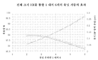
도 5는 작동 코어의 개수에 대한 열교환기 유효성을 예시하는 차트이다.The following detailed description of the embodiments as well as the foregoing summary will be better understood when read together with the accompanying drawings. For purposes of illustration of the present invention, the drawings show preferred embodiments. However, the present invention is not limited to the specific means shown in the drawings.
1 is a schematic diagram of a power generation system in accordance with an embodiment of the present disclosure;
2 is a schematic diagram of a power generation system in accordance with another embodiment of the present disclosure;
3 is a schematic diagram of a power generation system in accordance with another embodiment of the present disclosure;
4 is a schematic diagram of a power generation system in accordance with another embodiment of the present disclosure;
Figure 5 is a chart illustrating heat exchanger effectiveness versus the number of working cores.
본 개시내용의 실시예는 압축기와 터빈을 포함하는 하나 이상의 코어를 선택적으로 가동시킴으로써 선택적으로 동력 출력을 상승시키도록 구성되는 시스템, 방법 및 엔진을 포함한다. 통상적인 열역학적 동력 발생 사이클은 대체로 해군용 추진과 같은 적용예에서 사용되는데, 여기서 정상적인 필요 동력 출력은 동력 발생 사이클의 최대 동력 출력의 15 내지 20%이다. 그럼에도 불구하고, 통상적인 열역학적 동력 발생 사이클은 100% 용량에서 최대 효율을 위해 설계되는데, 이는 사이클이 더 낮은 부하에서 작동될 때 비효율로 이어진다. 따라서, 선택적으로 가동 또는 정지될 수 있는 복수의 코어를 포함하는 초임계 유체 사이클이 효율을 최대화할 수 있다. 개시된 시스템은 정상 부하 상태 하에 단일 코어로 작동되도록 설계될 수도 있으며 그리고 필요시 추가적인 동력을 발생시키도록 추가적인 코어를 추가함으로써 동력 출력을 증가시키도록 구성될 수도 있다. 본 명세서에 개시된 바와 같이 복수의 코어를 이용하는 시스템은 그 개시내용이 본 명세서에서 원용되는 미국 특허 공보 2013/0180259호("259 공보") 및 국제출원 PCT/US2015/017679호("679 출원")에 개시되어 있는 동력 발생 시스템을 포함할 수 있다.Embodiments of the present disclosure include a system, method and engine configured to selectively raise the power output by selectively activating one or more cores comprising a compressor and a turbine. Conventional thermodynamic power generation cycles are generally used in applications such as propulsion for the Navy where the normal required power output is 15 to 20% of the maximum power output of the power generation cycle. Nevertheless, a typical thermodynamic power generation cycle is designed for maximum efficiency at 100% capacity, leading to inefficiency when the cycle is operated at a lower load. Thus, a supercritical fluid cycle comprising a plurality of cores, which can be selectively activated or deactivated, can maximize efficiency. The disclosed system may be designed to operate as a single core under normal load conditions and may be configured to increase power output by adding additional cores to generate additional power as needed. Systems using multiple cores as disclosed herein are described in U.S. Patent Publication No. 2013/0180259 ("259 publication") and International Application No. PCT / US2015 / 017679 (the "679 application"), the disclosures of which are incorporated herein by reference. The power generation system disclosed in US patent application Ser.
도 1은 작동 유체가 초임계 유체일 수 있는 제1 폐쇄형 브레이턴 사이클(92), 및 작동 유체가 주변 공기일 수 있는 제2 개방형 브레이턴 사이클(94)을 포함하는 동력 발생 시스템(10)을 도시한다. 제1 브레이턴 사이클(92) 및 제2 브레이턴 사이클(94)은 초임계 유체 유동 경로(96) 및 공기 유체 유동 경로(98)를 각각 포함한다. 일 실시예에서 유동 경로(96, 98)는 2개의 유동 경로(96, 98) 사이에서 초임계 유체와 공기 간의 혼합이 거의 유발되지 않거나 또는 전혀 유발되지 않도록 분리되어 있다.1 shows a power generation system 10 including a first closed type Braaton cycle 92 in which the working fluid can be a supercritical fluid and a second open type Braaton cycle 94 in which the working fluid can be ambient air, Lt; / RTI > The first and second brake turn cycles 92 and 94 include a supercritical fluid flow path 96 and an air fluid flow path 98, respectively. In one embodiment, the flow paths 96, 98 are separated such that mixing between the supercritical fluid and the air is less or less likely to occur between the two flow paths 96, 98.
동력 발생 시스템(10)은 초임계 유체 유동 경로(96)를 따라 배치된 복수의 코어(60, 70, 80)를 포함한다. 각각의 코어는 압축기(62, 72, 82) 및 터빈(64, 74, 84)을 포함한다. 또한, 각각의 코어는 동력 발생 시스템(10)이 작동 코어의 개수에 따라 다른 수준의 동력을 발생시키도록 선택적으로 작동되게 구성된다. 동력 발생 시스템(10)은 하나 이상의 열원(58), 및 유동 경로(96, 98)를 따라 연결된 복수의 열교환기를 또한 포함한다. 열교환기는 복수의 교차 사이클 열교환기(32, 36)를 포함한다. 본 명세서에서 사용된 바와 같이, "교차 사이클 열교환기"는 공기 흡입 사이클(94)로부터 공기 또는 공기와 연소 가스/열 양자를 수용할 뿐만 아니라 초임계 유체 사이클(92)로부터 초임계 유체를 수용하며 그리고 두 사이클에서 유체들 간에 열을 전달하는 열교환기를 지칭한다. 동력 발생 시스템(10)은 밸브, 유량계, 혼합 결합부(mixing junction), 및 동력 발생 시스템(10)의 작동을 제어하도록 구성된 하나 이상의 제어기를 또한 포함할 수도 있다.The power generation system 10 includes a plurality of cores 60, 70, 80 disposed along a supercritical fluid flow path 96. Each core includes compressors 62, 72, 82 and turbines 64, 74, 84. Each core is also configured to selectively operate the power generating system 10 to generate different levels of power depending on the number of working cores. The power generation system 10 also includes one or more heat sources 58 and a plurality of heat exchangers coupled along the flow paths 96, 98. The heat exchanger includes a plurality of cross-cycle heat exchangers (32, 36). As used herein, a "cross-cycle heat exchanger" receives both air or air and combustion gas / heat from an air intake cycle 94, as well as a supercritical fluid from the supercritical fluid cycle 92 And a heat exchanger that transfers heat between fluids in two cycles. The power generation system 10 may also include a valve, a flow meter, a mixing junction, and one or more controllers configured to control the operation of the power generation system 10.
초기에, 초임계 유체의 스트림(1)이 초임계 유체 유동 경로(96)를 따라 제1 코어(60)로 안내된다. 초임계 유체는 축류(axial), 반경류(radial), 복열식(recuperating) 또는 유사한 유형의 압축기일 수도 있는 제1 코어 압축기(62)의 입구에 공급된다. 압축기(62)는 제1 SCO2 압축기(62)로 지칭될 수도 있다. 압축기(62)는 터빈(64)에 작동적으로 연결된 샤프트를 포함한다. 터빈(64)은 제1 SCO2 터빈(64)으로 지칭될 수도 있다. 스트림(1)을 따라서 유량계가 제1 SCO2 압축기(62) 입구로 공급되는 초임계 유체의 유량을 측정하도록 실시될 수도 있다. 유량계는 초임계 유체 사이클(92) 내에서의 총 SCO2 질량의 제어뿐만 아니라 전이 유체 거동을 용이하게 한다. 일 실시예에서, 초임계 유체는 이하에서 기술되는 바와 같이 그 임계점에 가까운 온도와 압력으로 냉각 및 팽창된 후에 제1 SCO2 압축기(62)의 입구에 유입된다. "초임계 유체"라는 용어는 별개의 액체상과 기체상이 존재하지 않는 유체를 나타내며, 초임계 유체의 "임계점"이라는 용어는 물질이 초임계 상태에 있다고 할 수 있는 최저 온도와 압력을 나타낸다. "임계 온도" 및 "임계 압력"이라는 용어는 임계점에서의 온도 및 압력을 나타낸다. 이산화탄소에 있어서, 임계점은 대략 304.2°K 및 7.35㎫이다. 일 실시예에서, 압축기(110)에 유입되는 초임계 유체는 그 임계점의 적어도 ±2°K 내로 냉각된다. 다른 실시예에서, 제1 SCO2 압축기(62)에 유입되는 초임계 유체는 그 임계점의 ±1°K 내로 냉각된다. 또 다른 실시예에서, 제1 SCO2 압축기(62)에 유입되는 초임계 유체는 그 임계점의 ±.2°K 내로 냉각된다.Initially, a stream of supercritical fluid (1) is directed to the first core (60) along a supercritical fluid flow path (96). The supercritical fluid is supplied to the inlet of the first core compressor 62, which may be an axial, radial, recuperating or similar type of compressor. The compressor 62 may be referred to as a first SCO2 compressor 62. The compressor (62) includes a shaft operatively connected to the turbine (64). The turbine 64 may be referred to as a first SCO2 turbine 64. [ The flow meter may be adapted to measure the flow rate of the supercritical fluid supplied to the inlet of the first SCO2 compressor 62 along stream 1. The flow meter facilitates transition fluid behavior as well as control of the total SCO2 mass within supercritical fluid cycle 92. In one embodiment, the supercritical fluid is introduced into the inlet of the first SCO2 compressor 62 after being cooled and expanded to a temperature and pressure close to its critical point, as described below. The term "supercritical fluid" refers to a fluid in which there are no separate liquid and gaseous phases, and the term "critical point" of a supercritical fluid refers to the lowest temperature and pressure at which a material can be said to be in a supercritical state. The terms "critical temperature" and "critical pressure" refer to temperature and pressure at the critical point. For carbon dioxide, the critical point is approximately 304.2 K and 7.35 MPa. In one embodiment, the supercritical fluid entering the compressor 110 is cooled to at least +/- 2 degrees K of its critical point. In another embodiment, supercritical fluid entering the first SCO2 compressor 62 is cooled to within +/- 1 DEG K of its critical point. In yet another embodiment, the supercritical fluid entering the first SCO2 compressor 62 is cooled to within ± 0.2 ° K of its critical point.
제1 SCO2 압축기(62) 내에서의 압축 이후에, 압축된 초임계 유체의 배출 스트림(4)은 교차 사이클 열교환기(32)로 안내된다. 교차 사이클 열교환기(32) 내에서, 열이 유동 경로(98) 내의 공기로부터 압축된 초임계 유체로 전달된다. 가열된 초임계 유체 스트림(14)은 교차 사이클 열교환기(32)로부터 배출된다.After compression in the first SCO2 compressor 62, the outlet stream 4 of the compressed supercritical fluid is directed to the crossed cycle heat exchanger 32. In the cross-cycle heat exchanger 32, heat is transferred from the air in the flow path 98 to the compressed supercritical fluid. The heated supercritical fluid stream 14 is discharged from the crossed cycle heat exchanger 32.
교차 사이클 열교환기(32)로부터의 가열된 초임계 유체의 스트림(14)은 제1 SCO2 터빈(64)의 입구로 안내된다. 제1 SCO2 터빈(64)은 축류, 반경류, 혼합 유동식 또는 유사한 유형의 터빈일 수도 있다. 제1 SCO2 터빈(64)은 초임계 유체를 팽창시키며 그리고 연결 샤프트를 통해 제1 SCO2 압축기(62)를 구동시키는 샤프트 동력을 생성한다. 또한, 제1 SCO2 터빈(64)은 동력 발생 시스템(10)을 위한 제1 수준의 출력 동력을 제공하기 위해 발전기에 작동적으로 연결될 수도 있다.The stream of heated supercritical fluid 14 from the crossed cycle heat exchanger 32 is directed to the inlet of the first SCO2 turbine 64. The first SCO2 turbine 64 may be an axial, radial, mixed flow or similar type of turbine. The first SCO2 turbine 64 expands the supercritical fluid and generates shaft power that drives the first SCO2 compressor 62 through the connection shaft. The first SCO2 turbine 64 may also be operatively connected to the generator to provide a first level of output power for the power generation system 10. [
팽창된 초임계 유체는 제1 SCO2 터빈(64)으로부터 배출되고 그리고 팽창된 초임계 유체의 배출 스트림(17)으로 안내된다. 팽창된 초임계 유체의 배출 스트림(17)은 교차 사이클 열교환기(36)로 안내된다. 교차 사이클 열교환기(36) 내에서, 팽창된 초임계 유체는 유동 경로(98)를 따라 교차 사이클 열교환기(36)를 통과하는 공기의 유동에 의해 냉각된다.The expanded supercritical fluid is withdrawn from the first SCO2 turbine 64 and directed into the effluent stream 17 of the expanded supercritical fluid. The effluent stream 17 of the expanded supercritical fluid is directed to a crossed cycle heat exchanger 36. Within the crossed cycle heat exchanger 36, the expanded supercritical fluid is cooled by the flow of air passing through the crossed cycle heat exchanger 36 along the flow path 98.
냉각된 초임계 유체의 스트림은 교차 사이클 열교환기(36)로부터 배출되고 그리고 스트림(1)으로서 제1 SCO2 압축기(62)의 입구로 안내된다. 대안적인 실시예에서, 교차 사이클 열교환기(36)로부터 배출된 냉각된 초임계 유체의 스트림은 제1 SCO2 압축기(62)의 입구로 복귀되기 전에 초임계 유체의 온도를 추가로 저감시키기 위해 적어도 하나의 냉각기로 안내될 수도 있다. 추가적인 초임계 유체는 시스템으로부터의 초임계 유체의 임의의 누출을 보상하기 위해 스트림(1)으로 도입될 수도 있다. 어떤 경우에도, 초임계 유체 스트림(1)은 제1 SCO2 압축기(62)의 입구로 안내되며 그리고 압축-가열-팽창-냉각의 단계는 반복된다.A stream of cooled supercritical fluid is withdrawn from the crossed cycle heat exchanger 36 and directed to the inlet of the first SCO2 compressor 62 as stream 1. In an alternative embodiment, the stream of cooled supercritical fluid discharged from the cascade cycle heat exchanger (36) is at least one stream of additional supercritical fluid to further reduce the temperature of the supercritical fluid prior to returning to the inlet of the first SCO2 compressor (62) Of the cooler. Additional supercritical fluids may be introduced into stream 1 to compensate for any leakage of supercritical fluid from the system. In any case, the supercritical fluid stream 1 is directed to the inlet of the first SCO2 compressor 62 and the steps of compression-heating-expansion-cooling are repeated.
동력 발생 시스템(10)에 대한 동력 수요가 증가된 경우, 제1 코어(60)만이 작동 중일 때 발생된 제1 수준의 동력보다 큰 제2 수준의 동력을 발생시키기 위해 초임계 유체 유동 경로(96)를 따르는 제2 코어(70)가 가동될 수도 있다.When the power demand for the power generation system 10 is increased, a supercritical fluid flow path 96 (see FIG. 2) is used to generate a second level of power that is greater than the first level of power generated when only the first core 60 is operating The second core 70 may be operated.
제2 수준의 동력을 발생시키기 위해, 초임계 유체의 스트림(1)의 적어도 일부가 초임계 유체 유동 경로(96)를 따라 제2 코어(70)로 안내된다. 초임계 유체는 제2 SCO2 압축기(72)로 지칭될 수도 있는 제2 코어 압축기(72)의 입구로 공급된다.At least a portion of stream 1 of supercritical fluid is directed to second core 70 along supercritical fluid flow path 96 to generate a second level of power. The supercritical fluid is supplied to the inlet of a second core compressor 72, which may be referred to as a second SCO2 compressor 72.
제2 SCO2 압축기(72) 내에서의 압축 이후에, 압축된 초임계 유체의 배출물은 압축된 초임계 유체의 스트림(4)에서 제1 SCO2 압축기(62)로부터 배출된 압축된 초임계 유체와 혼합된다. 압축된 초임계 유체가 교차 사이클 열교환기(32) 내에서 가열된 후에, 가열된 초임계 유체의 스트림(14)의 적어도 일부가 제2 SCO2 터빈(74)의 입구로 안내된다.After compression in the second SCO2 compressor 72, the effluent of the compressed supercritical fluid is mixed with the compressed supercritical fluid discharged from the first SCO2 compressor 62 in the stream of compressed supercritical fluid 4 do. After the compressed supercritical fluid is heated in the cross cycle heat exchanger 32, at least a portion of the stream 14 of heated supercritical fluid is directed to the inlet of the second SCO2 turbine 74. [
제2 SCO2 터빈(74)은 초임계 유체를 팽창시키며 그리고 연결 샤프트를 통해 제2 SCO2 압축기(72)를 구동시키는 샤프트 동력을 생성한다. 또한, 제2 SCO2 터빈(74)은 제2 SCO2 터빈(74)이 동력 발생 시스템(10)을 위한 출력 동력을 제1 수준에서 제2 수준으로 상승시킨다.The second SCO2 turbine 74 generates shaft power that expands the supercritical fluid and drives the second SCO2 compressor 72 through the connection shaft. The second SCO2 turbine 74 also causes the second SCO2 turbine 74 to raise the output power for the power generation system 10 from the first level to the second level.
팽창된 초임계 유체는 제2 SCO2 터빈(74)으로부터 배출되고 그리고 팽창된 초임계 유체의 배출 스트림(17)에서 제1 SCO2 터빈(64)으로부터 배출된 팽창된 초임계 유체와 혼합된다. 팽창된 초임계 유체의 배출 스트림(17)은 교차 사이클 열교환기(36) 내에서 냉각되고 그리고 냉각된 초임계 유체의 적어도 일부가 스트림(1)으로서 제2 SCO2 압축기(72)의 입구로 안내된다.The expanded supercritical fluid is discharged from the second SCO2 turbine 74 and mixed with the expanded supercritical fluid discharged from the first SCO2 turbine 64 in the discharge stream 17 of the expanded supercritical fluid. The effluent stream 17 of the expanded supercritical fluid is cooled in the crossed cycle heat exchanger 36 and at least a portion of the cooled supercritical fluid is directed as stream 1 to the inlet of the second SCO2 compressor 72 .
동력 발생 시스템(10)에 대한 동력 수요가 추가로 증가된 경우, 제1 코어(60)와 제2 코어(70)가 작동 중일 때 발생된 제2 수준의 동력보다 큰 제3 수준의 동력을 발생시키기 위해 초임계 유체 유동 경로(96)를 따르는 제3 코어(80)가 가동될 수도 있다.When the power demand for the power generating system 10 is further increased, a third level of power is generated that is greater than the second level of power generated when the first core 60 and the second core 70 are operating The third core 80 along the supercritical fluid flow path 96 may be actuated.
제3 수준의 동력을 발생시키기 위해, 초임계 유체의 스트림(1)의 적어도 일부가 초임계 유체 유동 경로(96)를 따라 제3 코어(80)로 안내된다. 초임계 유체는 제3 SCO2 압축기(82)로 지칭될 수도 있는 제3 코어 압축기(82)의 입구로 공급된다.At least a portion of the stream 1 of supercritical fluid is directed to the third core 80 along the supercritical fluid flow path 96 to generate a third level of power. The supercritical fluid is supplied to the inlet of a third core compressor 82, which may be referred to as a third SCO2 compressor 82.
제3 SCO2 압축기(82) 내에서의 압축 이후에, 압축된 초임계 유체의 배출물은 압축된 초임계 유체의 스트림(4)에서 제1 SCO2 압축기(62)와 제2 SCO2 압축기(72)로부터 배출된 압축된 초임계 유체와 혼합된다. 압축된 초임계 유체가 교차 사이클 열교환기(32) 내에서 가열된 후에, 가열된 초임계 유체의 스트림(14)의 적어도 일부가 제3 SCO2 터빈(84)의 입구로 안내된다.After compression in the third SCO2 compressor 82 the effluent of the compressed supercritical fluid is discharged from the first SCO2 compressor 62 and the second SCO2 compressor 72 in the stream 4 of compressed supercritical fluid Lt; RTI ID = 0.0 > supercritical < / RTI > After the pressurized supercritical fluid is heated in the crossed cycle heat exchanger 32, at least a portion of the stream 14 of heated supercritical fluid is directed to the inlet of the third SCO2 turbine 84.
제3 SCO2 터빈(84)은 초임계 유체를 팽창시키며 그리고 연결 샤프트를 통해 제3 SCO2 압축기(82)를 구동시키는 샤프트 동력을 생성한다. 또한, 제3 SCO2 터빈(84)은 제3 SCO2 터빈(84)이 동력 발생 시스템(10)을 위한 출력 동력을 제2 수준에서 제3 수준으로 상승시킨다.The third SCO2 turbine 84 generates shaft power that expands the supercritical fluid and drives the third SCO2 compressor 82 through the connection shaft. The third SCO2 turbine 84 also causes the third SCO2 turbine 84 to raise the output power for the power generation system 10 from the second level to the third level.
팽창된 초임계 유체는 제3 SCO2 터빈(84)으로부터 배출되고 그리고 팽창된 초임계 유체의 배출 스트림(17)에서 제1 SCO2 터빈(64)과 제2 SCO2 터빈(74)으로부터 배출된 팽창된 초임계 유체와 혼합된다. 팽창된 초임계 유체의 배출 스트림(17)은 교차 사이클 열교환기(36) 내에서 냉각되고 그리고 냉각된 초임계 유체의 적어도 일부가 스트림(1)으로서 제3 SCO2 압축기(84)의 입구로 안내된다.The expanded supercritical fluid is discharged from the third SCO2 turbine 84 and discharged from the first SCO2 turbine 64 and the second SCO2 turbine 74 from the expanded stream 17 of the expanded supercritical fluid, And mixed with the critical fluid. The effluent stream 17 of the expanded supercritical fluid is cooled in the crossed cycle heat exchanger 36 and at least a portion of the cooled supercritical fluid is directed as stream 1 to the inlet of the third SCO2 compressor 84 .
도 1을 계속 참조하면, 동력 발생 시스템(10)의 공기 흡입 사이클(94) 부분은 개방형 유동 경로(98)를 형성한다. 초기에, 주변 공기는 유동 경로(98)를 따라 교차 사이클 열교환기(36)로 공급된다. 공기는 후속하여 열원(58) 내에서 가열되고 그리고 유동 경로(98)를 따라 교차 사이클 열교환기(32)를 통해 안내된다. 열원(58)은 화석 연료 또는 다른 연료 유형의 연료와 같은 연료의 스트림을 수용하도록 구성된 연소기일 수 있다. 열원(58)은 또한 시스템 열을 생성하는 태양열 집열기 또는 원자로에 의해, 또는 폐기물, 생물량 또는 생물 유도 연료의 연소를 포함하는 몇몇 다른 열원에 의해 작동될 수 있다.Continuing to refer to FIG. 1, the portion of the air intake cycle 94 of the power generation system 10 forms an open flow path 98. Initially, ambient air is supplied to the crossed cycle heat exchanger 36 along flow path 98. The air is subsequently heated within the heat source 58 and directed through the crossed cycle heat exchanger 32 along the flow path 98. The heat source 58 may be a combustor configured to receive a stream of fuel, such as fossil fuel or other fuel type fuel. The heat source 58 may also be operated by a solar collector or reactor that generates system heat, or by some other heat source including combustion of waste, biomass or bio-induced fuel.
본 개시내용의 상기 실시예에는 3개의 코어만이 기술되어있지만, 동력 발생 시스템(10)은 3개의 코어에 제한되지 않는다. 동력 발생 시스템(10)은 동력 발생 시스템(10)을 위한 최대 요구 동력 출력을 생성하기 위해 4개의 코어, 5개의 코어, 6개의 코어 또는 추가적인 코어를 포함할 수도 있다.Although only three cores are described in the above embodiment of the present disclosure, the power generation system 10 is not limited to three cores. The power generation system 10 may include four cores, five cores, six cores, or additional cores to generate the maximum demand power output for the power generation system 10. [
본 개시내용의 다른 실시예에 따른 동력 발생 시스템(100)의 개략도인 도 2를 참조한다. 동력 발생 시스템(100)은 제1 초임계 유체 사이클(102) 및 제2 또는 공기 흡입 사이클(104)을 포함한다는 점에서 동력 발생 시스템(10)과 유사하다. 제1 및 제2 사이클(102, 104)은 초임계 유체 유동 경로(106) 및 공기 유체 유동 경로(108)를 각각 포함하는데, 이들 유동 경로는 일 실시예에선 초임계 유체와 공기가 혼합되지 않도록 서로 분리되어 있다.Reference is now made to Fig. 2, which is a schematic illustration of a power generation system 100 in accordance with another embodiment of the present disclosure. The power generation system 100 is similar to the power generation system 10 in that it includes a first supercritical fluid cycle 102 and a second or air intake cycle 104. The first and second cycles 102 and 104 include a supercritical fluid flow path 106 and an air fluid flow path 108, respectively, which, in one embodiment, Are separated from each other.
동력 발생 시스템(100)은 초임계 유체 유동 경로(106)를 따라 배치된 복수의 코어를 포함한다. 각각의 코어는 터빈에 작동적으로 연결된 샤프트를 갖춘 압축기를 포함한다. 일 실시예에서, 터빈은 출력 장치에 작동적으로 연결된 샤프트를 또한 포함한다. 대안적인 실시예에서, 코어는 출력 장치에 작동적으로 연결된 제2 터빈을 포함하며, 압축기에 작동적으로 연결된 터빈으로부터 배출된 팽창된 초임계 유체는 출력 장치를 위한 샤프트 동력을 생성하는 제2 터빈을 통해 순환된다. 다른 실시예에서, 출력 장치는 출력 동력을 동력 발생 시스템(100)에 제공할 수도 있다. 또한, 각각의 코어는 동력 발생 시스템(100)이 작동 코어의 개수에 따라 다른 수준의 동력을 발생시키도록 선택적으로 작동되게 구성될 수도 있다. 본 명세서에 기술된 바와 같이, 출력 장치는 터보프롭, 터보샤프트, 기어박스 또는 발전기일 수 있다.The power generation system 100 includes a plurality of cores disposed along a supercritical fluid flow path 106. Each core includes a compressor with a shaft operatively connected to the turbine. In one embodiment, the turbine also includes a shaft operatively connected to the output device. In an alternate embodiment, the core includes a second turbine operatively connected to the output device, and the expanded supercritical fluid discharged from the turbine operatively connected to the compressor includes a second turbine generating shaft power for the output device, Lt; / RTI > In an alternative embodiment, the output device may provide output power to the power generation system 100. In addition, each core may be configured to selectively operate the power generating system 100 to generate different levels of power depending on the number of working cores. As described herein, the output device may be a turboprop, a turbo shaft, a gear box, or a generator.
도 2에 도시된 바와 같이, 초임계 유체 유동 경로(106)를 따라 배치된 복수의 코어의 제1 코어는 샤프트(112a)를 통해 터빈(114a)에 작동적으로 연결된 압축기(110a)를 포함한다. 터빈(114a)은 제1 수준의 출력 동력을 동력 발생 시스템(100)에 제공하는 출력 장치(120a)에 작동적으로 연결된 샤프트(117a)를 추가로 포함한다. 초임계 유체 유동 경로(106)를 따라 배치된 복수의 코어의 제2 코어는 샤프트(112b)를 통해 터빈(114b)에 작동적으로 연결된 압축기(110b)를 포함한다. 터빈(114b)은 제1 코어와 제2 코어가 작동 중일 때 제1 코어만이 작동 중일 때의 제1 수준의 출력 동력보다 큰 제2 수준의 출력 동력을 동력 발생 시스템(100)에 제공하는 출력 장치(120b)에 작동적으로 연결된 샤프트(117b)를 추가로 포함한다. 동력 발생 시스템(100)의 설계시, 초임계 유체 유동 경로(106)를 따라 배치된 복수의 코어의 총 코어수는 임의의 특정 코어수에 제한되지 않는다.2, a first core of a plurality of cores disposed along a supercritical fluid flow path 106 includes a compressor 110a operatively connected to a turbine 114a through a shaft 112a . The turbine 114a further includes a shaft 117a operatively connected to an output device 120a that provides a first level of output power to the power generation system 100. [ The second core of the plurality of cores disposed along the supercritical fluid flow path 106 includes a compressor 110b operatively connected to the turbine 114b through a shaft 112b. The turbine 114b includes an output (not shown) that provides a second level of output power to the power generation system 100 that is greater than the first level output power when only the first core is operating when the first and second cores are operating. And further includes a shaft 117b operatively connected to the device 120b. In designing the power generation system 100, the total number of cores of the plurality of cores disposed along the supercritical fluid flow path 106 is not limited to any particular number of cores.
도 2에 도시된 바와 같이, 바람직한 총 코어수에 이를 때까지 추가적인 코어가 특정 적용예에 기초하여 추가될 수도 있다. 총 코어수는 초임계 유체 유동 경로(106)를 따라 배치된 "최종 코어"로 도 2에 표시되어 있으며, 이 최종 코어는 샤프트(112x)를 통해 터빈(114x)에 작동적으로 연결된 압축기(110x)를 포함한다. "최종 코어"라는 용어는 참조의 편의를 위해 사용되며 그리고 초임계 유체 유동 경로(106)를 따라 배치된 복수의 코어의 전체 코어 또는 모든 코어가 작동 중인 상태 또는 경우를 나타낸다. 터빈(114x)은 동력 발생 시스템(100)을 위한 추가적인 수준의 출력 동력을 제공하는 출력 장치(120x)에 작동적으로 연결된 샤프트(117x)를 추가로 포함한다. 따라서, 동력 발생 시스템(100) 내의 총 코어수는 동력 발생 시스템(100)을 위한 출력 동력의 수준의 개수를 한정한다. 따라서, 동력 발생 시스템(100)을 위한 출력 동력은 동력 발생 시스템(100) 내의 초임계 유체 유동 경로(106)를 따라 작동 코어의 작동 중인 코어의 수를 선택적으로 가동 및/또는 정지시킴으로써 조절될 수도 있다.As shown in FIG. 2, additional cores may be added based on the particular application until the desired total number of cores is reached. The total core number is shown in Figure 2 as a "final core" disposed along the supercritical fluid flow path 106, which is connected to a compressor 110x operatively connected to the turbine 114x via a shaft 112x ). The term "final core" is used for convenience of reference and indicates the state or case in which the entire core or all of the cores of a plurality of cores disposed along the supercritical fluid flow path 106 are operating. The turbine 114x further includes a shaft 117x operatively connected to an output device 120x that provides an additional level of output power for the power generating system 100. Thus, the total number of cores in the power generation system 100 defines the number of levels of output power for the power generation system 100. Thus, the output power for the power generating system 100 may be adjusted by selectively activating and / or stopping the number of working cores of the working core along the supercritical fluid flow path 106 in the power generation system 100 have.
초임계 사이클(102) 내의 각각의 코어는 초임계 유체 유동 경로(106)를 따라 각각의 코어 내외로의 초임계 유체의 유동을 제어하기 위해 압축기 입력 밸브(142a, 142b, 142x), 압축기 배출 밸브(144a, 144b, 144x), 터빈 입력 밸브(146a, 146b, 146x) 및 터빈 출력 밸브(148a, 148b, 148x)를 또한 포함할 수도 있다.Each core in the supercritical cycle 102 is connected to a compressor inlet valve 142a, 142b, 142x, a compressor outlet valve 142a, 142b, 142x to control the flow of supercritical fluid into and out of each core along the supercritical fluid flow path 106, 144b, 144x, turbine input valves 146a, 146b, 146x and turbine output valves 148a, 148b, 148x.
동력 발생 시스템(100)은 공기 유동 경로(104)를 따라 배치된 하나 이상의 압축기, 하나 이상의 터빈 및 하나 이상의 연소기, 및 유동 경로(106, 108)를 따라 배치된 복수의 열교환기를 추가로 포함한다. 열교환기는 복수의 교차 사이클 열교환기(132, 134, 136, 138)를 포함한다.The power generation system 100 further includes one or more compressors disposed along the air flow path 104, one or more turbines and one or more combustors, and a plurality of heat exchangers disposed along the flow path (106, 108). The heat exchanger includes a plurality of cross-cycle heat exchangers (132, 134, 136, 138).
동력 발생 시스템(100)은 초임계 유체 유동 경로(106)를 따라 복열식 열교환기(130)를 또한 포함한다. 본 명세서에서 사용된 바와 같이, "복열식 열교환기"라는 용어는 복수의 코어의 적어도 하나의 터빈(114a, 114b, 114x)으로부터 배출된 터빈 배출 스트림(17) 내의 팽창된 초임계 유체와 초임계 유체 유동 경로(106)를 따라 배치된 복수의 코어의 적어도 하나의 압축기(110a, 110b, 110x)로부터 배출된 압축기 배출 스트림(4) 내의 압축된 초임계 유체 사이의 열전달을 나타낸다. 동력 발생 시스템(100)은 밸브(122), (도시 안 된)유량계, 혼합 결합부(124), 및 동력 발생 시스템(100)의 작동을 제어하도록 구성된 (도시 안 된)하나 이상의 제어기를 또한 포함할 수도 있다.The power generation system 100 also includes a recuperative heat exchanger 130 along the supercritical fluid flow path 106. As used herein, the term "recuperated heat exchanger" refers to an expanded supercritical fluid in a turbine exhaust stream 17 discharged from at least one turbine 114a, 114b, 114x of a plurality of cores, Represent heat transfer between the compressed supercritical fluid in the compressor discharge stream (4) discharged from at least one compressor (110a, 110b, 110x) of a plurality of cores disposed along the fluid flow path (106). The power generation system 100 also includes a valve 122, a flow meter (not shown), a mixing engagement 124, and one or more controllers (not shown) configured to control the operation of the power generation system 100 You may.
초기에, 초임계 유체의 스트림(1)은 초임계 유체 유동 경로(106)를 따라 제1 코어로 안내된다. 초임계 유체는 제1 코어 압축기(110a)의 입구로 공급된다. 압축기(110a) 내에서의 압축 이후에, 압축된 초임계 유체는 압축기 배출 스트림(4)으로 배출된다. 대안적인 실시예에서, 스트림(1)은 초임계 유체의 스트림(2a)을 제1 코어 압축기(110a)의 입구로 안내하는 압축기 입력 밸브(142a)로 안내된다. 압축기(110a) 내에서의 압축 이후에, 압축된 초임계 유체는 압축된 초임계 유체를 압축기 배출 스트림(4)으로 안내하는 압축기 배출 밸브(144a)로 스트림(3a)에 의해 배출된다.Initially, stream 1 of supercritical fluid is directed to the first core along supercritical fluid flow path 106. The supercritical fluid is supplied to the inlet of the first core compressor 110a. After compression in the compressor 110a, the compressed supercritical fluid is discharged to the compressor discharge stream 4. In an alternate embodiment, stream 1 is directed to a compressor input valve 142a that directs a stream of supercritical fluid 2a into the inlet of the first core compressor 110a. After compression in the compressor 110a, the compressed supercritical fluid is discharged by the stream 3a into a compressor discharge valve 144a that directs the compressed supercritical fluid to the compressor discharge stream 4.
압축기 배출 스트림(4)은 배출 스트림(6)과 배출 스트림(8)과 같이 제1 및 제2 부분으로 분할될 수도 있다. 배출 스트림(6)과 배출 스트림(8)은 제1 및 제2 배출 스트림(6, 8)으로 지칭될 수도 있다. 대안적으로, 배출 스트림(6)과 배출 스트림(8)은 제1 및 제2 압축기 배출 스트림(6, 8)으로 지칭될 수도 있다. 그런 분할로 인해 압축기 배출 스트림(4)의 제1 부분은 복열되고 그리고 나머지 부분은 유동 경로(108)를 통한 공기 유체 순환으로 일련의 열교환기(134, 132)에 의해 직접 가열될 수 있다. 도시된 바와 같이, 압축기 배출 스트림(4)은 (도시 안 된)제어기와 전자 통신할 수 있는 밸브(122a)를 통해 분할된다. 제어기는 필요에 따라 유동을 유동 경로(106)를 통해 안내하기 위해 밸브(122a)를 작동 또는 가동시킨다. 일 실시예에서, 밸브(122a)는 압축기 배출 스트림(4)의 55% 내지 약 75%를 제1 배출 스트림(6)으로 안내하도록 구성된다. 압축기 배출 스트림(4)의 유동의 나머지 부분은 제2 배출 스트림(8)으로 안내된다. 다른 실시예에서, 밸브(122a)는 압축기 배출 스트림(4)의 약 67%를 제1 배출 스트림(6)으로 안내하도록 구성된다.The compressor discharge stream (4) may be divided into first and second parts, such as the discharge stream (6) and the discharge stream (8). The outlet stream (6) and the outlet stream (8) may be referred to as first and second outlet streams (6, 8). Alternatively, the discharge stream 6 and the discharge stream 8 may be referred to as first and second compressor discharge streams 6, 8. Due to such a split, the first portion of the compressor discharge stream 4 may be recuperated and the remainder may be directly heated by a series of heat exchangers 134, 132 with air fluid circulation through the flow path 108. As shown, the compressor discharge stream 4 is divided through a valve 122a which is in electronic communication with the controller (not shown). The controller actuates or actuates the valve 122a to guide the flow through the flow path 106 as needed. In one embodiment, the valve 122a is configured to direct 55% to about 75% of the compressor discharge stream 4 to the first outlet stream 6. The remainder of the flow of the compressor discharge stream (4) is directed to the second discharge stream (8). In another embodiment, the valve 122a is configured to direct approximately 67% of the compressor discharge stream 4 to the first outlet stream 6.
초임계 유체의 제1 배출 스트림(6)은 복열식 열교환기(130)로 안내되며, 이 복열식 열교환기에서 열이 제2 터빈 배출 스트림(22) 내의 가열된 초임계 유체로부터 제1 압축기 배출 스트림(6)으로 전달된다. 복열식 열교환기(130)로부터 배출된 가열된 초임계 유체의 스트림(19)은 결합부(124a)로 안내되고 그리고 교차 사이클 열교환기(134)를 빠져나가는 가열된 초임계 유체의 스트림(10)과 혼합된다.The first outlet stream (6) of supercritical fluid is directed to a recuperative heat exchanger (130) where heat is transferred from the heated supercritical fluid in the second turbine exhaust stream (22) to the first compressor outlet Stream 6 as shown in FIG. The heated supercritical fluid stream 19 discharged from the recuperative heat exchanger 130 is directed to the engaging portion 124a and passes through a stream of heated supercritical fluid 10 exiting the intersystem cycle heat exchanger 134, .
제2 배출 스트림(8)은 교차 사이클 열교환기(134)로 안내된다. 교차 사이클 열교환기(134) 내에서, 유동 경로(108) 내의 연소 가스로부터의 열이 초임계 유체의 제2 배출 스트림(8)으로 전달된다. 열교환기(134)로부터 배출된 스트림(10)은 상술된 바와 같은 결합부(124a)에서 복열식 열교환기(130)로부터의 초임계 유체의 스트림(19)과 혼합된다. 결합부(124a)는 도관에 연결되는 조인트일 수도 있거나 또는 혼합 장치를 포함할 수도 있다.The second outlet stream (8) is directed to a crossed cycle heat exchanger (134). In the crossed cycle heat exchanger 134, heat from the combustion gas in the flow path 108 is transferred to the second outlet stream 8 of supercritical fluid. The stream 10 discharged from heat exchanger 134 is mixed with stream 19 of supercritical fluid from recuperative heat exchanger 130 at engaging portion 124a as described above. The engagement portion 124a may be a joint connected to the conduit or may include a mixing device.
혼합된 스트림(12)은 교차 사이클 열교환기(132)로 공급된다. 교차 사이클 열교환기(132) 내에서, 열이 유동 경로(108) 내의 연소 가스로부터 초임계 유체의 혼합된 스트림으로 전달된다. 교차 사이클 열교환기(132)는 터빈 입력 스트림(14)내로 가열된 초임계 유체를 배출한다.The mixed stream 12 is fed to a crossed cycle heat exchanger 132. In the cross-cycle heat exchanger 132, heat is transferred from the combustion gas in the flow path 108 to the mixed stream of supercritical fluid. The crossed cycle heat exchanger 132 discharges the heated supercritical fluid into the turbine input stream 14.
터빈 입력 스트림(14) 내의 가열된 초임계 유체는 제1 코어 터빈(114a)의 입구로 안내된다. 터빈(114a)은 초임계 유체를 팽창시키며 그리고 샤프트(112a)를 통해 압축기(110a)를 구동시키는 샤프트 동력을 생성한다. 터빈(114a)은 또한 동력 발생 시스템(100)에 제1 수준의 출력 동력을 제공하기 위해 출력 장치(120a)를 구동시킨다. 터빈(114a) 내에서의 팽창 이후에, 팽창된 초임계 유체는 터빈 배출 스트림(17)으로 배출된다. 대안적인 실시예에서, 터빈 입력 스트림(14) 내의 가열된 초임계 유체는 초임계 유체의 스트림(15a)을 제1 코어 터빈(114a)의 입구로 안내하는 터빈 입력 밸브(146a)로 안내된다. 터빈(114a)은 초임계 유체를 팽창시키며 그리고 샤프트(112a)를 통해 압축기(110a)를 구동시키는 샤프트 동력을 생성한다. 터빈(114a)은 또한 동력 발생 시스템(100)에 제1 수준의 출력 동력을 제공하기 위해 출력 장치(120a)를 구동시킨다. 터빈(114a) 내에서의 팽창 이후에, 팽창된 초임계 유체는 초임계 유체를 터빈 배출 스트림(17)으로 안내하는 터빈 배출 밸브(148a)로 스트림(16a)에 의해 배출된다.The heated supercritical fluid in the turbine input stream 14 is directed to the inlet of the first core turbine 114a. The turbine 114a expands the supercritical fluid and generates shaft power that drives the compressor 110a through the shaft 112a. Turbine 114a also drives output device 120a to provide a first level of output power to power generation system 100. [ After expansion in the turbine 114a, the expanded supercritical fluid is discharged to the turbine effluent stream 17. In an alternate embodiment, the heated supercritical fluid in the turbine input stream 14 is directed to a turbine input valve 146a that directs a stream 15a of supercritical fluid to the inlet of the first core turbine 114a. The turbine 114a expands the supercritical fluid and generates shaft power that drives the compressor 110a through the shaft 112a. Turbine 114a also drives output device 120a to provide a first level of output power to power generation system 100. [ After expansion in the turbine 114a, the expanded supercritical fluid is discharged by the stream 16a into a turbine discharge valve 148a that directs the supercritical fluid to the turbine discharge stream 17.
터빈 배출 스트림(17)은 배출 스트림(18)과 배출 스트림(22)과 같이 제1 및 제2 부분으로 분할될 수도 있다. 배출 스트림(18)과 배출 스트림(22)은 제1 및 제2 배출 스트림(18, 22)으로 지칭될 수도 있다. 대안적으로, 배출 스트림(18)과 배출 스트림(22)은 제1 및 제2 터빈 배출 스트림(18, 22)으로 지칭될 수도 있다. 도시된 바와 같이, 밸브(122b)는 터빈 배출 스트림(17)을 제1 및 제2 배출 스트림(18, 22)으로 분할시킬 수 있다. 제어기는 밸브(122b)를 작동 또는 가동시킨다. 일 실시예에서, 밸브(122b)는 터빈 배출 스트림(17)의 70% 내지 약 90%를 제2 배출 스트림(22)으로 안내하도록 구성된다. 터빈 배출 스트림(17)의 유동의 나머지 부분은 제1 배출 스트림(18)으로 안내된다. 다른 실시예에서, 밸브(122b)는 터빈 배출 스트림(17)의 약 80%를 제2 배출 스트림(22)으로 안내하도록 구성된다. 터빈 배출 스트림(17)이 어떻게 분할되는지와는 상관 없이, 제1 배출 스트림(18)은 교차 사이클 열교환기(136)로 안내되고 그리고 유동 경로(108)를 따라 교차 사이클 열교환기(136)를 통과하는 공기의 유동에 의해 냉각된다.The turbine exhaust stream 17 may be divided into first and second portions, such as the exhaust stream 18 and the exhaust stream 22. The outlet stream 18 and the outlet stream 22 may be referred to as first and second outlet streams 18,22. Alternatively, the exhaust stream 18 and the exhaust stream 22 may be referred to as first and second turbine exhaust streams 18, 22. As shown, the valve 122b may divide the turbine discharge stream 17 into first and second discharge streams 18,22. The controller actuates or actuates the valve 122b. In one embodiment, the valve 122b is configured to direct 70% to about 90% of the turbine effluent stream 17 to the second effluent stream 22. The remaining portion of the flow of the turbine exhaust stream 17 is directed to the first exhaust stream 18. In another embodiment, the valve 122b is configured to direct approximately 80% of the turbine effluent stream 17 to the second effluent stream 22. Regardless of how the turbine exhaust stream 17 is divided, the first outlet stream 18 is directed to the crossed cycle heat exchanger 136 and flows along the flow path 108 to the crossed cycle heat exchanger 136 Lt; / RTI >
제2 배출 스트림(22)은 복열식 열교환기(130)로 안내되며, 이 복열식 열교환기에서 제2 터빈 배출 스트림(22) 내의 초임계 유체로부터의 열이 제1 압축기 배출 스트림(6) 내의 압축된 초임계 유체로 전달된다. 다시 말하면, 복열식 열교환기(130)는 초임계 유체의 터빈 배출 스트림(22)을 냉각시킨다. 복열식 열교환기(130)로부터의 냉각된 초임계 유체의 배출 스트림(24)은 결합부(124b)에서 교차 사이클 열교환기(136)로부터의 유입 스트림(20)과 혼합된다. 결합부(124b)로부터, 혼합된 스트림(26)은 (선택 사항일 수도 있는)교차 사이클 열교환기(138)로 안내된다. 예컨대, 혼합된 스트림(26)은 냉각된 초임계 유체의 스트림(28)으로 직접 안내된다. 상술된 바와 같이, 교차 사이클 열교환기(138) 내에서 초임계 유체의 혼합된 스트림(26)으로부터의 열이 공기 사이클(104)의 유동 경로(108)로 전달된다. 냉각된 초임계 유체의 스트림(28)은 (선택 사항일 수도 있는)냉각기(126)를 통해 안내되어 초임계 유체의 스트림(1)으로 복귀된다. 공급부(109)로부터의 추가적인 초임계 유체가 시스템으로부터의 초임계 유체의 임의의 누출을 보상하기 위해 초임계 유체의 스트림(1)으로 도입될 수 있다. 어떤 경우에도, 초임계 유체 스트림(1)은 제1 코어 압축기(110a)의 입구로 복귀되며 그리고 압축-가열-팽창-냉각의 단계는 반복된다.The second exhaust stream 22 is directed to a recuperative heat exchanger 130 where heat from the supercritical fluid in the second turbine exhaust stream 22 in the recuperative heat exchanger is directed into the first compressor discharge stream 6 Lt; RTI ID = 0.0 > supercritical fluid. In other words, the recuperative heat exchanger 130 cools the turbine exhaust stream 22 of the supercritical fluid. The cooled supercritical fluid discharge stream 24 from the recuperative heat exchanger 130 is mixed with the inlet stream 20 from the cross cycle heat exchanger 136 at the engaging portion 124b. From the coupling portion 124b, the combined stream 26 is directed to a crossed cycle heat exchanger 138 (which may be optional). For example, the mixed stream 26 is directed directly into the stream 28 of cooled supercritical fluid. Heat from the mixed stream 26 of supercritical fluid in the cascade cycle heat exchanger 138 is transferred to the flow path 108 in the air cycle 104, as described above. The cooled supercritical fluid stream 28 is directed through the cooler 126 (which may be optional) and returned to the supercritical fluid stream 1. Additional supercritical fluid from the feeder 109 may be introduced into the stream 1 of supercritical fluid to compensate for any leakage of the supercritical fluid from the system. In any case, the supercritical fluid stream 1 is returned to the inlet of the first core compressor 110a and the steps of compression-heating-expansion-cooling are repeated.
동력 발생 시스템(100)에 대한 동력 수요가 증가된 경우, 제1 코어만이 작동 중일 때 발생된 제1 수준의 동력보다 큰 제2 수준의 동력을 발생시키기 위해 초임계 유체 유동 경로(106)를 따르는 제2 코어가 가동될 수도 있다.When the power demand for the power generation system 100 is increased, a supercritical fluid flow path 106 is provided to generate a second level of power that is greater than the first level of power generated when only the first core is operating The following second core may be operated.
제2 수준의 동력을 발생시키기 위해, 초임계 유체의 스트림(1)의 적어도 일부가 초임계 유체 유동 경로(106)를 따라 제2 코어로 안내된다. 초임계 유체는 제2 코어 압축기(110b)의 입구로 공급된다. 압축기(110b) 내에서의 압축 이후에, 압축된 초임계 유체의 배출물은 압축기 배출 스트림(4)으로 안내되며, 이 압축기 배출 스트림에서 압축기(110a)으로부터 배출된 압축된 초임계 유체와 혼합된다. 대안적인 실시예에서, 스트림(1)의 적어도 일부가 초임계 유체의 스트림(2b)을 제2 코어 압축기(110b)의 입구로 안내하는 압축기 입력 밸브(142b)로 안내된다. 압축기(110b) 내에서의 압축 이후에, 압축된 초임계 유체는 압축된 초임계 유체를 압축기 배출 스트림(4)으로 안내하는 압축기 배출 밸브(144a)로 스트림(3b)에 의해 배출되며, 이 압축기 배출 스트림에서 압축기(110a)로부터 배출된 압축된 초임계 유체와 혼합된다.At least a portion of stream 1 of supercritical fluid is directed to the second core along supercritical fluid flow path 106 to generate a second level of power. The supercritical fluid is supplied to the inlet of the second core compressor 110b. After compression in the compressor 110b, the effluent of the compressed supercritical fluid is directed to the compressor discharge stream 4 and is mixed with the compressed supercritical fluid discharged from the compressor 110a in the compressor discharge stream. In an alternative embodiment, at least a portion of the stream 1 is directed to a compressor input valve 142b that directs stream 2b of supercritical fluid to the inlet of the second core compressor 110b. After compression in the compressor 110b, the compressed supercritical fluid is discharged by the stream 3b into a compressor discharge valve 144a which directs the compressed supercritical fluid to the compressor discharge stream 4, And mixed with the compressed supercritical fluid discharged from the compressor 110a in the discharge stream.
압축기 배출 스트림(4)은 분할되어 상술된 바와 같은 복열식 열교환기(130)와 교차 사이클 열교환기(132, 134)로 안내되며, 이들 열교환기에서 초임계 유체는 터빈 입력 스트림(14)으로서 가열되어 배출된다.The compressor discharge stream 4 is split and directed into a recuperative heat exchanger 130 and a cross cycle heat exchanger 132,134 as described above in which supercritical fluids are heated as turbine input stream 14 And then discharged.
터빈 입력 스트림(14) 내의 가열된 초임계 유체의 적어도 일부가 제2 코어 터빈(114b)의 입구로 안내된다. 터빈(114b)은 초임계 유체를 팽창시키며 그리고 샤프트(112b)를 통해 압축기(110b)를 구동시키는 샤프트 동력을 생성한다. 터빈(114b)은 또한 제1 코어만이 작동 중일 때의 제1 수준의 동력보다 큰 제2 수준의 출력 동력을 동력 발생 시스템(100)에 제공하기 위해 출력 장치(120b)를 구동시킨다. 터빈(114b) 내에서의 팽창 이후에, 팽창된 초임계 유체는 터빈 배출 스트림(17)으로 배출되며, 이 터빈 배출 스트림에서 터빈(114a)으로부터 배출된 팽창된 초임계 유체와 혼합된다. 대안적인 실시예에서, 터빈 입력 스트림(14) 내의 가열된 초임계 유체는 초임계 유체의 스트림(15b)을 제2 코어 터빈(114b)의 입구로 안내하는 터빈 입력 밸브(146b)로 안내된다. 터빈(114b)은 초임계 유체를 팽창시키며 그리고 샤프트(112b)를 통해 압축기(110b)를 구동시키는 샤프트 동력을 생성한다. 터빈(114b)은 또한 제1 코어만이 작동 중일 때의 제1 수준의 동력보다 큰 제2 수준의 출력 동력을 동력 발생 시스템(100)에 제공하기 위해 출력 장치(120b)를 구동시킨다. 터빈(114b) 내에서의 팽창 이후에, 팽창된 초임계 유체는 초임계 유체를 터빈 배출 스트림(17)으로 안내하는 터빈 배출 밸브(148b)로 스트림(16b)에 의해 배출되며, 이 터빈 배출 스트림에서 터빈(114a)으로부터 배출된 팽창된 초임계 유체와 혼합된다.At least a portion of the heated supercritical fluid in the turbine input stream 14 is directed to the inlet of the second core turbine 114b. The turbine 114b expands the supercritical fluid and generates shaft power that drives the compressor 110b through the shaft 112b. The turbine 114b also drives the output device 120b to provide a second level of output power to the power generation system 100 that is greater than the first level of power when only the first core is operating. After expansion in the turbine 114b, the expanded supercritical fluid is discharged to the turbine discharge stream 17 and is mixed with the expanded supercritical fluid discharged from the turbine 114a in the turbine discharge stream. In an alternate embodiment, the heated supercritical fluid in the turbine input stream 14 is directed to a turbine input valve 146b that directs a stream 15b of supercritical fluid to the inlet of the second core turbine 114b. The turbine 114b expands the supercritical fluid and generates shaft power that drives the compressor 110b through the shaft 112b. The turbine 114b also drives the output device 120b to provide a second level of output power to the power generation system 100 that is greater than the first level of power when only the first core is operating. After expansion in turbine 114b, the expanded supercritical fluid is discharged by stream 16b into turbine discharge valve 148b, which directs the supercritical fluid to turbine discharge stream 17, Is mixed with the expanded supercritical fluid discharged from the turbine 114a.
터빈 배출 스트림(17)은 분할되어 상술된 바와 같은 복열식 열교환기(130)와 교차 사이클 열교환기(136, 138)로 안내되며, 이들 열교환기에서 팽창된 초임계 유체는 냉각되고 그리고 스트림(1) 내의 냉각된 초임계 유체의 적어도 일부가 제2 코어 압축기(110b)의 입구로 안내된다.The turbine exhaust stream 17 is split and directed to a recuperative heat exchanger 130 and a cross cycle heat exchanger 136,138 as described above wherein the supercritical fluid expanded in these heat exchangers is cooled and stream 1 At least a portion of the cooled supercritical fluid in the second core compressor 110b is directed to the inlet of the second core compressor 110b.
동력 발생 시스템(100)에 대한 동력 수요가 추가로 증가된 경우, 제1 코어와 제2 코어가 작동 중일 때 발생된 제2 수준의 동력보다 큰 추가적인 수준의 동력을 발생시키기 위해 초임계 유체 유동 경로(106)를 따르는 추가적인 코어가 가동될 수도 있다. 추가적인 수준의 동력은 상술된 방식으로 초임계 유체를 추가적인 코어를 통해 유동시킴으로써 발생된다. 동력 발생 시스템(100)을 위한 최고 수준의 출력 동력은 초임계 유체 유동 경로(106)를 따라 배치된 코어 모두가 작동 중일 때 생성된다.When the power demand for the power generation system 100 is further increased, a supercritical fluid flow path < RTI ID = 0.0 > 0.0 > 106 < / RTI > An additional level of power is generated by flowing the supercritical fluid through the additional core in the manner described above. The highest level of output power for the power generation system 100 is generated when all of the cores disposed along the supercritical fluid flow path 106 are operating.
최고 수준의 동력을 발생시키기 위해, 초임계 유체의 스트림(1)의 적어도 일부가 초임계 유체 유동 경로(106)를 따라 최종 코어로 안내된다. 초임계 유체는 최종 코어 압축기(110x)의 입구로 공급된다. 압축기(110x) 내에서의 압축 이후에, 압축된 초임계 유체의 배출물은 압축기 배출 스트림(4)으로 안내되며, 이 압축기 배출 스트림에서 압축기(110a), 압축기(110b) 및 추가적인 코어 압축기로부터 배출된 압축된 초임계 유체와 혼합된다. 대안적인 실시예에서, 스트림(1)의 적어도 일부가 초임계 유체의 스트림(2x)을 최종 코어 압축기(110x)의 입구로 안내하는 압축기 입력 밸브(142x)로 안내된다. 압축기(110x) 내에서의 압축 이후에, 압축된 초임계 유체는 압축된 초임계 유체를 압축기 배출 스트림(4)으로 안내하는 압축기 배출 밸브(144x)로 스트림(3x)에 의해 배출되며, 이 압축기 배출 스트림에서 압축기(110a), 압축기(110b) 및 추가적인 코어 압축기로부터 배출된 압축된 초임계 유체와 혼합된다.At least a portion of stream 1 of supercritical fluid is directed to the final core along supercritical fluid flow path 106 to generate the highest level of power. The supercritical fluid is supplied to the inlet of the final core compressor 110x. After compression in compressor 110x, the effluent of the compressed supercritical fluid is directed to compressor discharge stream 4 where it is discharged from compressor 110a, compressor 110b and additional core compressor And mixed with the compressed supercritical fluid. In an alternative embodiment, at least a portion of the stream 1 is directed to a compressor input valve 142x that directs a stream of supercritical fluid 2x into the inlet of the final core compressor 110x. After compression in the compressor 110x, the compressed supercritical fluid is discharged by the stream 3x into a compressor discharge valve 144x which directs the compressed supercritical fluid to the compressor discharge stream 4, Is mixed with the compressed supercritical fluid discharged from the compressor (110a), the compressor (110b) and the additional core compressor in the exhaust stream.
압축기 배출 스트림(4)은 분할되어 상술된 바와 같은 복열식 열교환기(130)와 교차 사이클 열교환기(132, 134)로 안내되며, 이들 열교환기에서 초임계 유체는 터빈 입력 스트림(14)으로서 가열되어 배출된다.The compressor discharge stream 4 is split and directed into a recuperative heat exchanger 130 and a cross cycle heat exchanger 132,134 as described above in which supercritical fluids are heated as turbine input stream 14 And then discharged.
터빈 입력 스트림(14) 내의 가열된 초임계 유체의 적어도 일부가 최종 코어 터빈(114x)의 입구로 안내된다. 터빈(114x)은 초임계 유체를 팽창시키며 그리고 샤프트(112x)를 통해 압축기(110x)를 구동시키는 샤프트 동력을 생성한다. 터빈(114x)은 또한 모든 코어가 작동 중일 때 최고 수준의 출력 동력을 동력 발생 시스템(100)에 제공하기 위해 출력 장치(120x)를 구동시킨다. 터빈(114x) 내에서의 팽창 이후에, 팽창된 초임계 유체는 터빈 배출 스트림(17)으로 배출되며, 이 터빈 배출 스트림에서 터빈(114a), 터빈(114b) 및 추가적인 코어 터빈으로부터 배출된 팽창된 초임계 유체와 혼합된다. 대안적인 실시예에서, 터빈 입력 스트림(14) 내의 가열된 초임계 유체는 초임계 유체의 스트림(15x)을 최종 코어 터빈(114x)의 입구로 안내하는 터빈 입력 밸브(146x)로 안내된다. 터빈(114x)은 초임계 유체를 팽창시키며 그리고 샤프트(112x)를 통해 압축기(110x)를 구동시키는 샤프트 동력을 생성한다. 터빈(114x)은 또한 모든 코어가 작동 중일 때 최고 수준의 출력 동력을 동력 발생 시스템(100)에 제공하기 위해 출력 장치(120x)를 구동시킨다. 터빈(114x) 내에서의 팽창 이후에, 팽창된 초임계 유체는 초임계 유체를 터빈 배출 스트림(17)으로 안내하는 터빈 배출 밸브(148x)로 스트림(16x)에 의해 배출되며, 이 터빈 배출 스트림에서 터빈(114a), 터빈(114b) 및 추가적인 코어 터빈으로부터 배출된 팽창된 초임계 유체와 혼합된다.At least a portion of the heated supercritical fluid in the turbine input stream 14 is directed to the inlet of the final core turbine 114x. Turbine 114x expands the supercritical fluid and generates shaft power that drives compressor 110x through shaft 112x. Turbine 114x also drives output device 120x to provide the highest level of output power to power generation system 100 when all cores are operating. After expansion in the turbine 114x, the expanded supercritical fluid is discharged to the turbine discharge stream 17 where it is discharged from the turbine 114a, turbine 114b and the additional core turbine, And mixed with the supercritical fluid. In an alternate embodiment, the heated supercritical fluid in the turbine input stream 14 is directed to a turbine input valve 146x that directs a stream of supercritical fluid 15x to the inlet of the final core turbine 114x. Turbine 114x expands the supercritical fluid and generates shaft power that drives compressor 110x through shaft 112x. Turbine 114x also drives output device 120x to provide the highest level of output power to power generation system 100 when all cores are operating. After expansion in the turbine 114x, the expanded supercritical fluid is discharged by the stream 16x into a turbine discharge valve 148x that directs the supercritical fluid to the turbine discharge stream 17, Is mixed with the expanded supercritical fluid discharged from the turbine 114a, the turbine 114b and the additional core turbine.
터빈 배출 스트림(17)은 분할되어 상술된 바와 같은 복열식 열교환기(130)와 교차 사이클 열교환기(136, 138)로 안내되며, 이들 열교환기에서 팽창된 초임계 유체는 냉각되고 그리고 스트림(1) 내의 냉각된 초임계 유체의 적어도 일부가 최종 코어 압축기(110x)의 입구로 안내된다.The turbine exhaust stream 17 is split and directed to a recuperative heat exchanger 130 and a cross cycle heat exchanger 136,138 as described above wherein the supercritical fluid expanded in these heat exchangers is cooled and stream 1 0.0 > 110x < / RTI > is guided to the inlet of the final core compressor 110x.
도 2를 계속 참조하면, 동력 발생 시스템(100)의 공기 흡입 사이클(104) 부분은 개방형 유동 경로(108)를 형성한다. 초기에, 주변 공기(101)가 축류, 반경류, 복열식 또는 유사한 유형의 압축기일 수도 있는 공기 흡입 압축기(150)에 공급된다. 압축기(150)는 터빈(154)에 작동적으로 연결된 샤프트(152)를 포함한다. 압축기(150)로부터의 압축된 공기의 스트림(30)은 후속하여 상술된 바와 같은 열교환기(130, 136)로부터 배출된 초임계 유체의 혼합된 스트림(26)으로부터의 열의 전달에 의해 (선택 사항일 수도 있는)열교환기(138) 내에서 가열된다. 가열된 압축 공기의 스트림(32)은 후속하여 열교환기(136)로 안내되며, 이 열교환기에서 제1 터빈 배출 스트림(18) 내의 초임계 유체로부터의 열이 압축 공기의 스트림(32)으로 전달된다. 배출 스트림(34)은 연소기(158)로 안내된다. 연소기(158)는 터빈(154)의 터빈 입구에서의 필요 온도를 초과하게 압축 공기 스트림(34)의 온도를 상승시킨다. 압축기(150)는 터빈(154)에 의해 동력이 공급된 샤프트(152)를 통해 작동될 수 있다. 연소기(158)는 화석 연료 또는 다른 연료 유형과 같은 연료(103)의 스트림을 수용할 수 있다. 연소기(158)는 시스템 열을 생성하는 태양열 집열기 또는 원자로에 의해, 또는 폐기물, 생물량 또는 생물 유도 연료의 연소를 포함하는 몇몇 다른 열원에 의해 작동될 수 있다. 연소기(158)로부터의 연소 가스의 배출 스트림(36)은 터빈(154)으로 안내되며, 이 터빈에서 팽창될 수도 있다. 팽창된 고온 연소 가스의 스트림(40)은 열교환기(132)로 안내되며, 이 열교환기에서 열이 고온 연소 가스로부터 상술된 초임계 유체의 혼합된 스트림(12)으로 전달된다. 열교환기(132)를 빠져나간 후에, 고온 연소 가스의 스트림(41)은 열교환기(134)로 안내되며, 이 열교환기에서 열이 고온 연소 가스로부터 상술된 바와 같은 제2 압축기 배출 스트림(8) 내의 압축된 초임계 유체로 전달된다. 열교환기(134)의 배출 스트림(107)은 대기로 배기될 수도 있다.2, the portion of the air intake cycle 104 of the power generation system 100 forms an open flow path 108. As shown in FIG. Initially, the ambient air 101 is supplied to an air intake compressor 150, which may be an axial, radial, regenerative or similar type of compressor. The compressor 150 includes a shaft 152 operatively connected to a turbine 154. The stream 30 of compressed air from the compressor 150 is then delivered by heat transfer from the mixed stream 26 of supercritical fluid discharged from the heat exchangers 130 and 136 as described above Heat exchanger < RTI ID = 0.0 > 138 < / RTI > The stream of heated compressed air 32 is subsequently directed to a heat exchanger 136 where heat from the supercritical fluid in the first turbine exhaust stream 18 is conducted to a stream 32 of compressed air do. The outlet stream 34 is directed to the combustor 158. The combustor 158 raises the temperature of the compressed air stream 34 to exceed the required temperature at the turbine inlet of the turbine 154. The compressor 150 may be operated via a shaft 152 that is powered by a turbine 154. The combustor 158 may receive a stream of fuel 103, such as fossil fuel or other fuel types. The combustor 158 may be operated by a solar collector or reactor that produces system heat, or by some other heat source, including combustion of waste, biomass, or bio-derived fuel. The exhaust stream 36 of combustion gases from the combustor 158 is directed to the turbine 154 and may be expanded in the turbine. Stream 40 of expanded hot combustion gases is directed to a heat exchanger 132 where heat is transferred from the hot combustion gases to the mixed stream 12 of the supercritical fluid described above. After exiting the heat exchanger 132, the stream 41 of hot combustion gases is directed to a heat exchanger 134 where heat is transferred from the hot combustion gases to the second compressor discharge stream 8, Lt; RTI ID = 0.0 > supercritical < / RTI > The outlet stream 107 of the heat exchanger 134 may be vented to the atmosphere.
본 개시내용의 다른 실시예에 따른 동력 발생 시스템(200)의 개략도인 도 3을 참조한다. 동력 발생 시스템(200)은 동력 발생 시스템(100)과 거의 동일하므로, 동일한 도면부호가 동일한 구성요소를 식별하는데 사용된다. 동력 발생 시스템(200)에 있어서의 하나의 차이점은 동력 발생 시스템(200) 내의 각각의 코어가 출력 장치를 갖지 않는다는 점이다. 오히려, 동력 발생 시스템(200)은 샤프트(118)를 통해 출력 장치(220)에 작동적으로 연결된 동력 터빈(116)을 포함하는데, 각각의 코어 내의 터빈으로부터 배출된 팽창된 초임계 유체는 출력 장치(220)를 위한 샤프트 동력을 생성하는 동력 터빈(116)을 통해 순환된다. 동력 터빈(116) 내에서의 팽창 이후에, 팽창된 초임계 유체는 복열식 열교환기 및 복수의 교차 사이클 열교환기를 향해 배출된다.Reference is now made to Fig. 3, which is a schematic illustration of a power generation system 200 in accordance with another embodiment of the present disclosure. The power generation system 200 is substantially identical to the power generation system 100, so that the same reference numerals are used to identify the same components. One difference in power generation system 200 is that each core in power generation system 200 does not have an output device. Rather, the power generation system 200 includes a power turbine 116 operatively connected to the output device 220 via a shaft 118, wherein the expanded supercritical fluid discharged from the turbine within each core is delivered to the output device < RTI ID = 0.0 > (116) which generates shaft power for the turbine (220). After expansion in the power turbine 116, the expanded supercritical fluid is discharged toward the recuperative heat exchanger and the plurality of cross-cycle heat exchangers.
동력 발생 시스템(200)은 제1 초임계 유체 사이클(202) 및 제2 또는 공기 흡입 사이클(204)을 포함한다. 제1 및 제2 사이클(202, 204)은 초임계 유체 유동 경로(106) 및 공기 유체 유동 경로(108)를 각각 포함하는데, 이들 유동 경로는 일 실시예에선 초임계 유체와 공기가 혼합되지 않도록 서로 분리되어 있다.The power generation system 200 includes a first supercritical fluid cycle 202 and a second or air intake cycle 204. The first and second cycles 202 and 204 include a supercritical fluid flow path 106 and an air fluid flow path 108, respectively, which, in one embodiment, Are separated from each other.
동력 발생 시스템(200)은 초임계 유체 유동 경로(106)를 따라 배치된 복수의 코어를 포함한다. 각각의 코어는 터빈에 작동적으로 연결된 샤프트를 갖춘 압축기를 포함한다. 또한, 각각의 코어는 동력 발생 시스템(200)이 작동 코어의 개수에 따라 다른 수준의 동력을 발생시키도록 선택적으로 작동되게 구성될 수도 있다.The power generation system 200 includes a plurality of cores disposed along a supercritical fluid flow path 106. Each core includes a compressor with a shaft operatively connected to the turbine. In addition, each core may be configured to selectively operate the power generating system 200 to generate different levels of power depending on the number of working cores.
도 3에 도시된 바와 같이, 초임계 유체 유동 경로(106)를 따라 배치된 복수의 코어의 제1 코어는 샤프트(112a)를 통해 터빈(114a)에 작동적으로 연결된 압축기(110a)를 포함한다. 제1 코어 터빈(114a)은 출력 장치(220)에서의 제1 수준의 출력 동력을 동력 발생 시스템(200)에 제공한다. 출력 장치(220)는 터보프롭, 터보샤프트, 기어박스 또는 발전기일 수도 있다. 초임계 유체 유동 경로(106)를 따라 배치된 복수의 코어의 제2 코어는 샤프트(112b)를 통해 터빈(114b)에 작동적으로 연결된 압축기(110b)를 포함한다. 제2 코어 터빈(114b)은 제1 코어와 제2 코어가 작동 중일 때 제1 코어만이 작동 중일 때의 제1 수준의 출력 동력보다 큰 출력 장치(220)에서의 제2 수준의 출력 동력을 동력 발생 시스템(200)에 제공한다. 동력 발생 시스템(200)의 설계시, 초임계 유체 유동 경로(106)를 따라 배치된 복수의 코어의 총 코어수는 임의의 특정 코어수에 제한되지 않는다. 도 3에 도시된 바와 같이, 바람직한 총 코어수에 이를 때까지 추가적인 코어가 특정 적용예에 기초하여 추가될 수도 있다. 총 코어수는 초임계 유체 유동 경로(106)를 따라 배치된 최종 코어로 도 3에 표시되어 있는데, 이 최종 코어는 샤프트(112x)를 통해 터빈(114x)에 작동적으로 연결된 압축기(110x)를 포함한다. 최종 코어 터빈(114x)은 모든 코어가 작동 중일 때 출력 장치(220)에서의 최고 수준의 출력 동력을 동력 발생 시스템(200)에 제공한다. 따라서, 동력 발생 시스템(200) 내의 총 코어수는 동력 발생 시스템(200)을 위한 출력 동력의 수준의 개수를 한정한다. 따라서, 동력 발생 시스템(200)을 위한 출력 동력은 동력 발생 시스템(200) 내의 초임계 유체 유동 경로(106)를 따라 배치된 제1 코어에서부터 전체 코어/최종 코어까지 작동 중인 개수의 코어를 선택적으로 가동 및/또는 정지시킴으로써 동적으로 조절될 수도 있다.3, a first core of a plurality of cores disposed along a supercritical fluid flow path 106 includes a compressor 110a operatively connected to a turbine 114a through a shaft 112a . The first core turbine 114a provides a first level of output power at the output device 220 to the power generation system 200. [ The output device 220 may be a turboprop, a turbo shaft, a gear box, or a generator. The second core of the plurality of cores disposed along the supercritical fluid flow path 106 includes a compressor 110b operatively connected to the turbine 114b through a shaft 112b. The second core turbine 114b is capable of outputting a second level of output power at the output device 220 that is greater than the first level output power when only the first core is operating when the first and second cores are operating To the power generation system (200). In designing the power generating system 200, the total number of cores of the plurality of cores disposed along the supercritical fluid flow path 106 is not limited to any particular number of cores. As shown in FIG. 3, additional cores may be added based on the particular application until a desired total number of cores is reached. The total number of cores is shown in Figure 3 as the final core disposed along the supercritical fluid flow path 106. This final core includes a compressor 110x operatively connected to the turbine 114x via a shaft 112x . The final core turbine 114x provides the power generation system 200 with the highest level of output power at the output device 220 when all of the cores are operating. Thus, the total number of cores in the power generation system 200 defines the number of levels of output power for the power generation system 200. Thus, the output power for the power generation system 200 can be selectively transferred from the first core disposed along the supercritical fluid flow path 106 in the power generation system 200 to the entire core / May be dynamically adjusted by actuating and / or stopping it.
초임계 사이클(202) 내의 각각의 코어는 초임계 유체 유동 경로(106)를 따라 각각의 코어 내외로의 초임계 유체의 유동을 제어하기 위해 압축기 입력 밸브(142a, 142b, 142x), 압축기 배출 밸브(144a, 144b, 144x), 터빈 입력 밸브(146a, 146b, 146x) 및 터빈 출력 밸브(148a, 148b, 148x)를 또한 포함할 수도 있다.Each core in the supercritical cycle 202 is connected to a compressor inlet valve 142a, 142b, 142x, a compressor discharge valve 142b, 144b, 144x, turbine input valves 146a, 146b, 146x and turbine output valves 148a, 148b, 148x.
동력 발생 시스템(200)은 공기 유동 경로(204)를 따라 배치된 하나 이상의 압축기, 하나 이상의 터빈 및 하나 이상의 연소기, 및 유동 경로(106, 108)를 따라 배치된 복수의 열교환기를 추가로 포함한다. 열교환기는 복수의 교차 사이클 열교환기(132, 134, 136, 138)를 포함한다.The power generation system 200 further includes one or more compressors disposed along the air flow path 204, one or more turbines and one or more combustors, and a plurality of heat exchangers disposed along the flow paths 106, The heat exchanger includes a plurality of cross-cycle heat exchangers (132, 134, 136, 138).
동력 발생 시스템(200)은 초임계 유체 유동 경로(106)를 따라 복열식 열교환기(130)를 또한 포함한다. 동력 발생 시스템(200)은 밸브(122), (도시 안 된)유량계, 혼합 결합부(124), 및 동력 발생 시스템(200)의 작동을 제어하도록 구성된 (도시 안 된)하나 이상의 제어기를 또한 포함할 수도 있다.The power generation system 200 also includes a recuperative heat exchanger 130 along the supercritical fluid flow path 106. The power generation system 200 also includes one or more controllers (not shown) configured to control the operation of the valve 122, the flow meter, the mixing interface 124, and the power generation system 200 You may.
초기에, 초임계 유체의 스트림(1)은 초임계 유체 유동 경로(106)를 따라 제1 코어로 안내된다. 초임계 유체는 제1 코어 압축기(110a)의 입구로 공급된다. 압축기(110a) 내에서의 압축 이후에, 압축된 초임계 유체는 압축기 배출 스트림(4)으로 배출된다. 대안적인 실시예에서, 스트림(1)은 초임계 유체의 스트림(2a)을 제1 코어 압축기(110a)의 입구로 안내하는 압축기 입력 밸브(142a)로 안내된다. 압축기(110a) 내에서의 압축 이후에, 압축된 초임계 유체는 압축된 초임계 유체를 압축기 배출 스트림(4)으로 안내하는 압축기 배출 밸브(144a)로 스트림(3a)에 의해 배출된다.Initially, stream 1 of supercritical fluid is directed to the first core along supercritical fluid flow path 106. The supercritical fluid is supplied to the inlet of the first core compressor 110a. After compression in the compressor 110a, the compressed supercritical fluid is discharged to the compressor discharge stream 4. In an alternate embodiment, stream 1 is directed to a compressor input valve 142a that directs a stream of supercritical fluid 2a into the inlet of the first core compressor 110a. After compression in the compressor 110a, the compressed supercritical fluid is discharged by the stream 3a into a compressor discharge valve 144a that directs the compressed supercritical fluid to the compressor discharge stream 4.
압축기 배출 스트림(4)은 배출 스트림(6)과 배출 스트림(8)과 같이 제1 및 제2 부분으로 분할될 수도 있다. 배출 스트림(6)과 배출 스트림(8)은 제1 및 제2 배출 스트림(6, 8)으로 지칭될 수도 있다. 대안적으로, 배출 스트림(6)과 배출 스트림(8)은 제1 및 제2 압축기 배출 스트림(6, 8)으로 지칭될 수도 있다. 그런 분할로 인해 압축기 배출 스트림(4)의 제1 부분은 복열되고 그리고 나머지 부분은 유동 경로(108)를 통한 공기 유체 순환으로 일련의 열교환기(134, 132)에 의해 직접 가열될 수 있다. 도시된 바와 같이, 압축기 배출 스트림(4)은 (도시 안 된)제어기와 전자 통신할 수 있는 밸브(122a)를 통해 분할된다. 제어기는 필요에 따라 유동을 유동 경로(106)를 통해 안내하기 위해 밸브(122a)를 작동 또는 가동시킨다. 일 실시예에서, 밸브(122a)는 압축기 배출 스트림(4)의 55% 내지 약 75%를 제1 배출 스트림(6)으로 안내하도록 구성된다. 압축기 배출 스트림(4)의 유동의 나머지 부분은 제2 배출 스트림(8)으로 안내된다. 다른 실시예에서, 밸브(122a)는 압축기 배출 스트림(4)의 약 67%를 제1 배출 스트림(6)으로 안내하도록 구성된다.The compressor discharge stream (4) may be divided into first and second parts, such as the discharge stream (6) and the discharge stream (8). The outlet stream (6) and the outlet stream (8) may be referred to as first and second outlet streams (6, 8). Alternatively, the discharge stream 6 and the discharge stream 8 may be referred to as first and second compressor discharge streams 6, 8. Due to such a split, the first portion of the compressor discharge stream 4 may be recuperated and the remainder may be directly heated by a series of heat exchangers 134, 132 with air fluid circulation through the flow path 108. As shown, the compressor discharge stream 4 is divided through a valve 122a which is in electronic communication with the controller (not shown). The controller actuates or actuates the valve 122a to guide the flow through the flow path 106 as needed. In one embodiment, the valve 122a is configured to direct 55% to about 75% of the compressor discharge stream 4 to the first outlet stream 6. The remainder of the flow of the compressor discharge stream (4) is directed to the second discharge stream (8). In another embodiment, the valve 122a is configured to direct approximately 67% of the compressor discharge stream 4 to the first outlet stream 6.
초임계 유체의 제1 배출 스트림(6)은 복열식 열교환기(130)로 안내되며, 이 복열식 열교환기에서 열이 제2 터빈 배출 스트림(22) 내의 가열된 초임계 유체로부터 제1 압축기 배출 스트림(6)으로 전달된다. 복열식 열교환기(130)로부터 배출된 가열된 초임계 유체의 스트림(19)은 결합부(124a)로 안내되고 그리고 교차 사이클 열교환기(134)를 빠져나가는 가열된 초임계 유체의 스트림(10)과 혼합된다.The first outlet stream (6) of supercritical fluid is directed to a recuperative heat exchanger (130) where heat is transferred from the heated supercritical fluid in the second turbine exhaust stream (22) to the first compressor outlet Stream 6 as shown in FIG. The heated supercritical fluid stream 19 discharged from the recuperative heat exchanger 130 is directed to the engaging portion 124a and passes through a stream of heated supercritical fluid 10 exiting the intersystem cycle heat exchanger 134, .
제2 배출 스트림(8)은 교차 사이클 열교환기(134)로 안내된다. 교차 사이클 열교환기(134) 내에서, 유동 경로(108) 내의 연소 가스로부터의 열이 초임계 유체의 제2 배출 스트림(8)으로 전달된다. 열교환기(134)로부터 배출된 스트림(10)은 상술된 바와 같은 결합부(124a)에서 복열식 열교환기(130)로부터의 초임계 유체의 스트림(19)과 혼합된다. 결합부(124a)는 도관에 연결되는 조인트일 수도 있거나 또는 혼합 장치를 포함할 수도 있다.The second outlet stream (8) is directed to a crossed cycle heat exchanger (134). In the crossed cycle heat exchanger 134, heat from the combustion gas in the flow path 108 is transferred to the second outlet stream 8 of supercritical fluid. The stream 10 discharged from heat exchanger 134 is mixed with stream 19 of supercritical fluid from recuperative heat exchanger 130 at engaging portion 124a as described above. The engagement portion 124a may be a joint connected to the conduit or may include a mixing device.
혼합된 스트림(12)은 교차 사이클 열교환기(132)로 공급된다. 교차 사이클 열교환기(132) 내에서, 열이 유동 경로(108) 내의 연소 가스로부터 초임계 유체의 혼합된 스트림으로 전달된다. 교차 사이클 열교환기(132)는 터빈 입력 스트림(14)내로 가열된 초임계 유체를 배출한다.The mixed stream 12 is fed to a crossed cycle heat exchanger 132. In the cross-cycle heat exchanger 132, heat is transferred from the combustion gas in the flow path 108 to the mixed stream of supercritical fluid. The crossed cycle heat exchanger 132 discharges the heated supercritical fluid into the turbine input stream 14.
터빈 입력 스트림(14) 내의 가열된 초임계 유체는 제1 코어 터빈(114a)의 입구로 안내된다. 터빈(114a)은 초임계 유체를 팽창시키며 그리고 샤프트(112a)를 통해 압축기(110a)를 구동시키는 샤프트 동력을 생성한다. 터빈(114a) 내에서의 팽창 이후에, 팽창된 초임계 유체는 터빈 배출 스트림(17)으로 배출된다. 대안적인 실시예에서, 터빈 입력 스트림(14) 내의 가열된 초임계 유체는 초임계 유체의 스트림(15a)을 제1 코어 터빈(114a)의 입구로 안내하는 터빈 입력 밸브(146a)로 안내된다. 터빈(114a)은 초임계 유체를 팽창시키고 그리고 샤프트(112a)를 통해 압축기(110a)를 구동시키는 샤프트 동력을 생성한다. 터빈(114a) 내에서의 팽창 이후에, 팽창된 초임계 유체는 초임계 유체를 터빈 배출 스트림(17)으로 안내하는 터빈 배출 밸브(148a)로 스트림(16a)에 의해 배출된다.The heated supercritical fluid in the turbine input stream 14 is directed to the inlet of the first core turbine 114a. The turbine 114a expands the supercritical fluid and generates shaft power that drives the compressor 110a through the shaft 112a. After expansion in the turbine 114a, the expanded supercritical fluid is discharged to the turbine effluent stream 17. In an alternate embodiment, the heated supercritical fluid in the turbine input stream 14 is directed to a turbine input valve 146a that directs a stream 15a of supercritical fluid to the inlet of the first core turbine 114a. The turbine 114a expands the supercritical fluid and generates shaft power that drives the compressor 110a through the shaft 112a. After expansion in the turbine 114a, the expanded supercritical fluid is discharged by the stream 16a into a turbine discharge valve 148a that directs the supercritical fluid to the turbine discharge stream 17.
터빈 배출 스트림(17)은 동력 터빈(116)의 입구로 안내되며, 여기서 해당 스트림은 제1 수준의 출력 동력을 동력 발생 시스템(200)에 제공하기 위해, 샤프트(118)를 통해 출력 장치(220)를 구동시키는 샤프트 동력을 발생시키도록 팽창된다. 동력 터빈(116) 내에서의 팽창 이후에, 팽창된 초임계 유체는 터빈 배출 스트림(17a)으로 안내된다.The turbine discharge stream 17 is directed to the inlet of the power turbine 116 where the stream is directed through the shaft 118 to the output device 220 To generate a shaft power. After expansion in the power turbine 116, the expanded supercritical fluid is directed to the turbine effluent stream 17a.
터빈 배출 스트림(17a)은 배출 스트림(18)과 배출 스트림(22)과 같이 제1 및 제2 부분으로 분할될 수도 있다. 배출 스트림(18)과 배출 스트림(22)은 제1 및 제2 배출 스트림(18, 22)으로 지칭될 수도 있다. 대안적으로, 배출 스트림(18)과 배출 스트림(22)은 제1 및 제2 터빈 배출 스트림(18, 22)으로 지칭될 수도 있다. 도시된 바와 같이, 밸브(122b)는 터빈 배출 스트림(17a)을 제1 및 제2 배출 스트림(18, 22)으로 분할시킬 수 있다. 제어기는 밸브(122b)를 작동 또는 가동시킨다. 일 실시예에서, 밸브(122b)는 터빈 배출 스트림(17a)의 70% 내지 약 90%를 제2 배출 스트림(22)으로 안내하도록 구성된다. 터빈 배출 스트림(17a)의 유동의 나머지 부분은 제1 배출 스트림(18)으로 안내된다. 다른 실시예에서, 밸브(122b)는 터빈 배출 스트림(17a)의 약 80%를 제2 배출 스트림(22)으로 안내하도록 구성된다. 터빈 배출 스트림(17a)이 어떻게 분할되는지와는 상관 없이, 제1 배출 스트림(18)은 교차 사이클 열교환기(136)로 안내되고 그리고 유동 경로(108)를 따라 교차 사이클 열교환기(136)를 통과하는 공기의 유동에 의해 냉각된다.The turbine exhaust stream 17a may be divided into first and second portions, such as the exhaust stream 18 and the exhaust stream 22. The outlet stream 18 and the outlet stream 22 may be referred to as first and second outlet streams 18,22. Alternatively, the exhaust stream 18 and the exhaust stream 22 may be referred to as first and second turbine exhaust streams 18, 22. As shown, the valve 122b may divide the turbine discharge stream 17a into first and second discharge streams 18,22. The controller actuates or actuates the valve 122b. In one embodiment, the valve 122b is configured to direct 70% to about 90% of the turbine effluent stream 17a to the second effluent stream 22. The remaining portion of the flow of the turbine exhaust stream 17a is directed to the first exhaust stream 18. In another embodiment, the valve 122b is configured to direct approximately 80% of the turbine effluent stream 17a to the second effluent stream 22. Regardless of how the turbine effluent stream 17a is divided, the first effluent stream 18 is directed to a crossed cycle heat exchanger 136 and passes through a crossed cycle heat exchanger 136 along a flow path 108 Lt; / RTI >
제2 배출 스트림(22)은 복열식 열교환기(130)로 안내되며, 여기서 해당 스트림은 제2 터빈 배출 스트림(22) 내의 초임계 유체로부터의 열이 제1 압축기 배출 스트림(6) 내의 압축된 초임계 유체로 전달된다. 다시 말하면, 복열식 열교환기(130)는 초임계 유체의 터빈 배출 스트림(22)을 냉각시킨다. 복열식 열교환기(130)로부터의 냉각된 초임계 유체의 배출 스트림(24)은 결합부(124b)에서 교차 사이클 열교환기(136)로부터의 유입 스트림(20)과 혼합된다. 결합부(124b)로부터, 혼합된 스트림(26)은 (선택 사항일 수도 있는)교차 사이클 열교환기(138)로 안내된다. 예컨대, 혼합된 스트림(26)은 냉각된 초임계 유체의 스트림(28)으로 직접 안내된다. 상술된 바와 같이, 교차 사이클 열교환기(138) 내에서 초임계 유체의 혼합된 스트림(26)으로부터의 열이 공기 사이클(204)의 유동 경로(108)로 전달된다. 냉각된 초임계 유체의 스트림(28)은 (선택 사항일 수도 있는)냉각기(126)를 통해 안내되어 초임계 유체의 스트림(1)으로 복귀된다. 공급부(109)로부터의 추가적인 초임계 유체가 시스템으로부터의 초임계 유체의 임의의 누출을 보상하기 위해 초임계 유체의 스트림(1)으로 도입될 수 있다. 어떤 경우에도, 초임계 유체 스트림(1)은 제1 코어 압축기(110a)의 입구로 복귀되며 그리고 압축-가열-팽창-냉각의 단계는 반복된다.The second effluent stream 22 is directed to a recuperative heat exchanger 130 where the heat is directed such that heat from the supercritical fluid in the second turbine effluent stream 22 is compressed And is delivered as a supercritical fluid. In other words, the recuperative heat exchanger 130 cools the turbine exhaust stream 22 of the supercritical fluid. The cooled supercritical fluid discharge stream 24 from the recuperative heat exchanger 130 is mixed with the inlet stream 20 from the cross cycle heat exchanger 136 at the engaging portion 124b. From the coupling portion 124b, the combined stream 26 is directed to a crossed cycle heat exchanger 138 (which may be optional). For example, the mixed stream 26 is directed directly into the stream 28 of cooled supercritical fluid. The heat from the mixed stream 26 of supercritical fluid in the cascade cycle heat exchanger 138 is transferred to the flow path 108 in the air cycle 204, as described above. The cooled supercritical fluid stream 28 is directed through the cooler 126 (which may be optional) and returned to the supercritical fluid stream 1. Additional supercritical fluid from the feeder 109 may be introduced into the stream 1 of supercritical fluid to compensate for any leakage of the supercritical fluid from the system. In any case, the supercritical fluid stream 1 is returned to the inlet of the first core compressor 110a and the steps of compression-heating-expansion-cooling are repeated.
동력 발생 시스템(200)에 대한 동력 수요가 증가된 경우, 제1 코어만이 작동 중일 때 발생된 제1 수준의 동력보다 큰 제2 수준의 동력을 출력 장치(220)에서 발생시키기 위해 초임계 유체 유동 경로(106)를 따르는 제2 코어가 가동될 수도 있다.When the power demand for the power generation system 200 is increased, the output of the supercritical fluid 220 to generate a second level of power in the output device 220 that is greater than the first level of power generated when only the first core is operating, The second core along the flow path 106 may be actuated.
제2 수준의 동력을 발생시키기 위해, 초임계 유체의 스트림(1)의 적어도 일부가 초임계 유체 유동 경로(106)를 따라 제2 코어로 안내된다. 초임계 유체는 제2 코어 압축기(110b)의 입구로 공급된다. 압축기(110b) 내에서의 압축 이후에, 압축된 초임계 유체의 배출물은 압축기 배출 스트림(4)으로 안내되며, 이 압축기 배출 스트림에서 압축기(110a)으로부터 배출된 압축된 초임계 유체와 혼합된다. 대안적인 실시예에서, 스트림(1)의 적어도 일부가 초임계 유체의 스트림(2b)을 제2 코어 압축기(110b)의 입구로 안내하는 압축기 입력 밸브(142b)로 안내된다. 압축기(110b) 내에서의 압축 이후에, 압축된 초임계 유체는 압축된 초임계 유체를 압축기 배출 스트림(4)으로 안내하는 압축기 배출 밸브(144a)로 스트림(3b)에 의해 배출되며, 이 압축기 배출 스트림에서 압축기(110a)로부터 배출된 압축된 초임계 유체와 혼합된다.At least a portion of stream 1 of supercritical fluid is directed to the second core along supercritical fluid flow path 106 to generate a second level of power. The supercritical fluid is supplied to the inlet of the second core compressor 110b. After compression in the compressor 110b, the effluent of the compressed supercritical fluid is directed to the compressor discharge stream 4 and is mixed with the compressed supercritical fluid discharged from the compressor 110a in the compressor discharge stream. In an alternative embodiment, at least a portion of the stream 1 is directed to a compressor input valve 142b that directs stream 2b of supercritical fluid to the inlet of the second core compressor 110b. After compression in the compressor 110b, the compressed supercritical fluid is discharged by the stream 3b into a compressor discharge valve 144a which directs the compressed supercritical fluid to the compressor discharge stream 4, And mixed with the compressed supercritical fluid discharged from the compressor 110a in the discharge stream.
압축기 배출 스트림(4)은 분할되어 상술된 바와 같은 복열식 열교환기(130)와 교차 사이클 열교환기(132, 134)로 안내되며, 이들 열교환기에서 초임계 유체는 터빈 입력 스트림(14)으로서 가열되어 배출된다.The compressor discharge stream 4 is split and directed into a recuperative heat exchanger 130 and a cross cycle heat exchanger 132,134 as described above in which supercritical fluids are heated as turbine input stream 14 And then discharged.
터빈 입력 스트림(14) 내의 가열된 초임계 유체의 적어도 일부가 제2 코어 터빈(114b)의 입구로 안내된다. 터빈(114b)은 초임계 유체를 팽창시키며 그리고 샤프트(112b)를 통해 압축기(110b)를 구동시키는 샤프트 동력을 생성한다. 터빈(114b) 내에서의 팽창 이후에, 팽창된 초임계 유체는 터빈 배출 스트림(17)으로 배출되며, 이 터빈 배출 스트림에서 터빈(114a)으로부터 배출된 팽창된 초임계 유체와 혼합된다. 대안적인 실시예에서, 터빈 입력 스트림(14) 내의 가열된 초임계 유체는 초임계 유체의 스트림(15b)을 제2 코어 터빈(114b)의 입구로 안내하는 터빈 입력 밸브(146b)로 안내된다. 터빈(114b)은 초임계 유체를 팽창시키며 그리고 샤프트(112b)를 통해 압축기(110b)를 구동시키는 샤프트 동력을 생성한다. 터빈(114b) 내에서의 팽창 이후에, 팽창된 초임계 유체는 초임계 유체를 터빈 배출 스트림(17)으로 안내하는 터빈 배출 밸브(148b)로 스트림(16b)에 의해 배출되며, 이 터빈 배출 스트림에서 터빈(114a)으로부터 배출된 팽창된 초임계 유체와 혼합된다.At least a portion of the heated supercritical fluid in the turbine input stream 14 is directed to the inlet of the second core turbine 114b. The turbine 114b expands the supercritical fluid and generates shaft power that drives the compressor 110b through the shaft 112b. After expansion in the turbine 114b, the expanded supercritical fluid is discharged to the turbine discharge stream 17 and is mixed with the expanded supercritical fluid discharged from the turbine 114a in the turbine discharge stream. In an alternate embodiment, the heated supercritical fluid in the turbine input stream 14 is directed to a turbine input valve 146b that directs a stream 15b of supercritical fluid to the inlet of the second core turbine 114b. The turbine 114b expands the supercritical fluid and generates shaft power that drives the compressor 110b through the shaft 112b. After expansion in turbine 114b, the expanded supercritical fluid is discharged by stream 16b into turbine discharge valve 148b, which directs the supercritical fluid to turbine discharge stream 17, Is mixed with the expanded supercritical fluid discharged from the turbine 114a.
터빈 배출 스트림(17)은 동력 터빈(116)의 입구로 안내되며, 이 동력 터빈에서 제1 코어만이 작동 중일 때의 제1 수준의 동력보다 큰 제2 수준의 출력 동력을 동력 발생 시스템(200)에 제공하기 위해 샤프트(118)를 통해 출력 장치(220)를 구동시키는 샤프트 동력을 생성하도록 팽창된다. 동력 터빈(116) 내에서의 팽창 이후에, 팽창된 초임계 유체는 터빈 배출 스트림(17a)으로 안내된다.The turbine discharge stream 17 is directed to the inlet of the power turbine 116 and is connected to a power output system 200 (see FIG. 2) for output power of a second level greater than that of the first level when only the first core is operating in the power turbine. To produce a shaft power that drives the output device 220 through the shaft 118 to provide power to the output device 220. The shaft < RTI ID = 0.0 > 118 < / RTI & After expansion in the power turbine 116, the expanded supercritical fluid is directed to the turbine effluent stream 17a.
터빈 배출 스트림(17a)은 분할되어 상술된 바와 같은 복열식 열교환기(130)와 교차 사이클 열교환기(136, 138)로 안내되며, 이들 열교환기에서 팽창된 초임계 유체는 냉각되고 그리고 스트림(1) 내의 냉각된 초임계 유체의 적어도 일부가 제2 코어 압축기(110b)의 입구로 안내된다.The turbine exhaust stream 17a is divided and directed to a recuperative heat exchanger 130 and a cross cycle heat exchanger 136,138 as described above wherein the supercritical fluid expanded in these heat exchangers is cooled and the stream 1 At least a portion of the cooled supercritical fluid in the second core compressor 110b is directed to the inlet of the second core compressor 110b.
동력 발생 시스템(200)에 대한 동력 수요가 추가로 증가된 경우, 제1 코어와 제2 코어가 작동 중일 때 발생된 제2 수준의 동력보다 큰 추가적인 수준의 동력을 발생시키기 위해 초임계 유체 유동 경로(106)를 따르는 추가적인 코어가 가동될 수도 있다. 추가적인 수준의 동력은 상술된 방식으로 초임계 유체를 추가적인 코어를 통해 유동시킴으로써 발생된다. 동력 발생 시스템(200)을 위한 최고 수준의 출력 동력은 초임계 유체 유동 경로(106)를 따라 배치된 코어 모두가 작동 중일 때 생성된다.When the power demand for the power generating system 200 is further increased, a supercritical fluid flow path < RTI ID = 0.0 > 0.0 > 106 < / RTI > An additional level of power is generated by flowing the supercritical fluid through the additional core in the manner described above. The highest level of output power for the power generating system 200 is generated when all of the cores disposed along the supercritical fluid flow path 106 are operating.
최고 수준의 동력을 발생시키기 위해, 초임계 유체의 스트림(1)의 적어도 일부가 초임계 유체 유동 경로(106)를 따라 최종 코어로 안내된다. 초임계 유체는 최종 코어 압축기(110x)의 입구로 공급된다. 압축기(110x) 내에서의 압축 이후에, 압축된 초임계 유체의 배출물은 압축기 배출 스트림(4)으로 안내되며, 이 압축기 배출 스트림에서 압축기(110a), 압축기(110b) 및 추가적인 코어 압축기로부터 배출된 압축된 초임계 유체와 혼합된다. 대안적인 실시예에서, 스트림(1)의 적어도 일부가 초임계 유체의 스트림(2x)을 최종 코어 압축기(110x)의 입구로 안내하는 압축기 입력 밸브(142x)로 안내된다. 압축기(110x) 내에서의 압축 이후에, 압축된 초임계 유체는 압축된 초임계 유체를 압축기 배출 스트림(4)으로 안내하는 압축기 배출 밸브(144x)로 스트림(3x)에 의해 배출되며, 이 압축기 배출 스트림에서 압축기(110a), 압축기(110b) 및 추가적인 코어 압축기로부터 배출된 압축된 초임계 유체와 혼합된다.At least a portion of stream 1 of supercritical fluid is directed to the final core along supercritical fluid flow path 106 to generate the highest level of power. The supercritical fluid is supplied to the inlet of the final core compressor 110x. After compression in compressor 110x, the effluent of the compressed supercritical fluid is directed to compressor discharge stream 4 where it is discharged from compressor 110a, compressor 110b and additional core compressor And mixed with the compressed supercritical fluid. In an alternative embodiment, at least a portion of the stream 1 is directed to a compressor input valve 142x that directs a stream of supercritical fluid 2x into the inlet of the final core compressor 110x. After compression in the compressor 110x, the compressed supercritical fluid is discharged by the stream 3x into a compressor discharge valve 144x which directs the compressed supercritical fluid to the compressor discharge stream 4, Is mixed with the compressed supercritical fluid discharged from the compressor (110a), the compressor (110b) and the additional core compressor in the exhaust stream.
압축기 배출 스트림(4)은 분할되어 상술된 바와 같은 복열식 열교환기(130)와 교차 사이클 열교환기(132, 134)로 안내되며, 이들 열교환기에서 초임계 유체는 터빈 입력 스트림(14)으로서 가열되어 배출된다.The compressor discharge stream 4 is split and directed into a recuperative heat exchanger 130 and a cross cycle heat exchanger 132,134 as described above in which supercritical fluids are heated as turbine input stream 14 And then discharged.
터빈 입력 스트림(14) 내의 가열된 초임계 유체의 적어도 일부가 최종 코어 터빈(114x)의 입구로 안내된다. 터빈(114x)은 초임계 유체를 팽창시키며 그리고 샤프트(112x)를 통해 압축기(110x)를 구동시키는 샤프트 동력을 생성한다. 터빈(114x) 내에서의 팽창 이후에, 팽창된 초임계 유체는 터빈 배출 스트림(17)으로 배출되며, 이 터빈 배출 스트림에서 터빈(114a), 터빈(114b) 및 추가적인 코어 터빈으로부터 배출된 팽창된 초임계 유체와 혼합된다. 대안적인 실시예에서, 터빈 입력 스트림(14) 내의 가열된 초임계 유체는 초임계 유체의 스트림(15x)을 최종 코어 터빈(114x)의 입구로 안내하는 터빈 입력 밸브(146x)로 안내된다. 터빈(114x)은 초임계 유체를 팽창시키며 그리고 샤프트(112x)를 통해 압축기(110x)를 구동시키는 샤프트 동력을 생성한다. 터빈(114x) 내에서의 팽창 이후에, 팽창된 초임계 유체는 초임계 유체를 터빈 배출 스트림(17)으로 안내하는 터빈 배출 밸브(148x)로 스트림(16x)에 의해 배출되며, 이 터빈 배출 스트림에서 터빈(114a), 터빈(114b) 및 추가적인 코어 터빈으로부터 배출된 팽창된 초임계 유체와 혼합된다.At least a portion of the heated supercritical fluid in the turbine input stream 14 is directed to the inlet of the final core turbine 114x. Turbine 114x expands the supercritical fluid and generates shaft power that drives compressor 110x through shaft 112x. After expansion in the turbine 114x, the expanded supercritical fluid is discharged to the turbine discharge stream 17 where it is discharged from the turbine 114a, turbine 114b and the additional core turbine, And mixed with the supercritical fluid. In an alternate embodiment, the heated supercritical fluid in the turbine input stream 14 is directed to a turbine input valve 146x that directs a stream of supercritical fluid 15x to the inlet of the final core turbine 114x. Turbine 114x expands the supercritical fluid and generates shaft power that drives compressor 110x through shaft 112x. After expansion in the turbine 114x, the expanded supercritical fluid is discharged by the stream 16x into a turbine discharge valve 148x that directs the supercritical fluid to the turbine discharge stream 17, Is mixed with the expanded supercritical fluid discharged from the turbine 114a, the turbine 114b and the additional core turbine.
터빈 배출 스트림(17)은 동력 터빈(116)의 입구로 안내되며, 이 동력 터빈에서 모든 코어가 작동 중일 때 최고 수준의 출력 동력을 동력 발생 시스템(200)에 제공하기 위해 샤프트(118)를 통해 출력 장치(220)를 구동시키는 샤프트 동력을 생성하도록 팽창된다. 동력 터빈(116) 내에서의 팽창 이후에, 팽창된 초임계 유체는 터빈 배출 스트림(17a)으로 안내된다.The turbine exhaust stream 17 is directed to the inlet of the power turbine 116 and through the shaft 118 to provide the highest level of output power to the power generating system 200 when all of the cores in the power turbine are operating. And is expanded to produce a shaft power that drives the output device 220. After expansion in the power turbine 116, the expanded supercritical fluid is directed to the turbine effluent stream 17a.
터빈 배출 스트림(17a)은 분할되어 상술된 바와 같은 복열식 열교환기(130)와 교차 사이클 열교환기(136, 138)로 안내되며, 이들 열교환기에서 팽창된 초임계 유체는 냉각되고 그리고 스트림(1) 내의 냉각된 초임계 유체의 적어도 일부가 최종 코어 압축기(110x)의 입구로 안내된다.The turbine exhaust stream 17a is divided and directed to a recuperative heat exchanger 130 and a cross cycle heat exchanger 136,138 as described above wherein the supercritical fluid expanded in these heat exchangers is cooled and the stream 1 0.0 > 110x < / RTI > is guided to the inlet of the final core compressor 110x.
도 3을 계속 참조하면, 동력 발생 시스템(200)의 공기 흡입 사이클(204) 부분은 상술된 전반적인 동력 발생 시스템(100)의 공기 흡입 사이클(104) 부분과 작동 및 구성이 동일하다.3, the air intake cycle 204 portion of the power generation system 200 is identical in operation and configuration to the air intake cycle 104 portion of the overall power generation system 100 described above.
본 개시내용의 다른 실시예에 따른 동력 발생 시스템(300)의 개략도인 도 4를 참조한다. 동력 발생 시스템(300)은 제1 초임계 유체 사이클(302) 및 제2 또는 공기 흡입 사이클(304)을 포함한다는 점에서 동력 발생 시스템(100)과 유사하다. 제1 및 제2 사이클(302, 304)은 초임계 유체 유동 경로(306) 및 공기 유체 유동 경로(423)를 각각 포함하는데, 이들 유동 경로는 일 실시예에선 초임계 유체와 공기가 혼합되지 않도록 서로 분리되어 있다. 그러나, 동력 발생 시스템(100)과는 달리, 동력 발생 시스템(300)은 초임계 유체 사이클(302) 내에 복열식 열교환기를 포함하지 않는다.Reference is now made to Fig. 4, which is a schematic illustration of a power generation system 300 in accordance with another embodiment of the present disclosure. The power generation system 300 is similar to the power generation system 100 in that it includes a first supercritical fluid cycle 302 and a second or air intake cycle 304. The first and second cycles 302 and 304 include a supercritical fluid flow path 306 and an air fluid flow path 423, respectively, which, in one embodiment, Are separated from each other. However, unlike the power generation system 100, the power generation system 300 does not include a recuperative heat exchanger in the supercritical fluid cycle 302.
동력 발생 시스템(300)은 초임계 유체 유동 경로(306)를 따라 배치된 복수의 코어를 포함한다. 각각의 코어는 터빈에 작동적으로 연결된 샤프트를 갖춘 압축기를 포함한다. 일 실시예에서, 터빈은 출력 장치에 작동적으로 연결된 샤프트를 또한 포함한다. 대안적인 실시예에서, 코어는 출력 장치에 작동적으로 연결된 제2 터빈을 포함하며, 압축기에 작동적으로 연결된 터빈으로부터 배출된 팽창된 초임계 유체는 출력 장치를 위한 샤프트 동력을 생성하는 제2 터빈을 통해 순환된다. 다른 실시예에서, 출력 장치는 출력 동력을 동력 발생 시스템(300)에 제공할 수도 있다. 또한, 각각의 코어는 동력 발생 시스템(300)이 작동 코어의 개수에 따라 다른 수준의 동력을 발생시키도록 선택적으로 작동되게 구성될 수도 있다. 본 명세서에 기술된 바와 같이, 출력 장치는 터보프롭, 터보팬, 기어박스 또는 발전기일 수도 있다.The power generation system 300 includes a plurality of cores disposed along a supercritical fluid flow path 306. Each core includes a compressor with a shaft operatively connected to the turbine. In one embodiment, the turbine also includes a shaft operatively connected to the output device. In an alternate embodiment, the core includes a second turbine operatively connected to the output device, and the expanded supercritical fluid discharged from the turbine operatively connected to the compressor includes a second turbine generating shaft power for the output device, Lt; / RTI > In an alternative embodiment, the output device may provide output power to the power generation system 300. In addition, each core may be configured to selectively operate the power generating system 300 to generate different levels of power depending on the number of operating cores. As described herein, the output device may be a turboprop, a turbo fan, a gear box, or a generator.
도 4에 도시된 바와 같이, 초임계 유체 유동 경로(306)를 따라 배치된 복수의 코어의 제1 코어는 샤프트(312a)를 통해 터빈(314a)에 작동적으로 연결된 압축기(310a)를 포함한다. 터빈(314a)은 제1 수준의 출력 동력을 동력 발생 시스템(300)에 제공하는 출력 장치(320a)에 작동적으로 연결된 샤프트(317a)를 추가로 포함한다. 초임계 유체 유동 경로(306)를 따라 배치된 복수의 코어의 제2 코어는 샤프트(312b)를 통해 터빈(314b)에 작동적으로 연결된 압축기(310b)를 포함한다. 터빈(314b)은 제1 코어와 제2 코어가 작동 중일 때 제1 코어만이 작동 중일 때의 제1 수준의 출력 동력보다 큰 제2 수준의 출력 동력을 동력 발생 시스템(300)에 제공하는 출력 장치(320b)에 작동적으로 연결된 샤프트(317b)를 추가로 포함한다. 동력 발생 시스템(300)의 설계시, 초임계 유체 유동 경로(306)를 따라 배치된 복수의 코어의 총 코어수는 임의의 특정 코어수에 제한되지 않는다.4, a first core of a plurality of cores disposed along a supercritical fluid flow path 306 includes a compressor 310a operatively connected to a turbine 314a through a shaft 312a . The turbine 314a further includes a shaft 317a operatively connected to an output device 320a that provides a first level of output power to the power generation system 300. [ The second core of the plurality of cores disposed along the supercritical fluid flow path 306 includes a compressor 310b operatively connected to the turbine 314b through a shaft 312b. The turbine 314b includes an output (not shown) that provides a second level of output power to the power generation system 300 that is greater than the first level output power when only the first core is operating when the first and second cores are operating. And further includes a shaft 317b operatively connected to the device 320b. In designing the power generation system 300, the total number of cores of the plurality of cores disposed along the supercritical fluid flow path 306 is not limited to any particular number of cores.
도 4에 도시된 바와 같이, 바람직한 총 코어수에 이를 때까지 추가적인 코어가 특정 적용예에 기초하여 추가될 수도 있다. 총 코어수는 도 4에 초임계 유체 유동 경로(306)를 따라 배치된 최종 코어로 표시되어 있는데, 이 최종 코어는 샤프트(312x)를 통해 터빈(314x)에 작동적으로 연결된 압축기(310x)를 포함한다. 터빈(314x)은 모든 코어가 작동 중일 때 최고 수준의 출력 동력을 동력 발생 시스템(300)에 제공하는 출력 장치(320x)에 작동적으로 연결된 샤프트(317x)를 추가로 포함한다. 따라서, 동력 발생 시스템(300) 내의 총 코어수는 동력 발생 시스템(300)을 위한 출력 동력의 수준의 개수를 한정한다. 따라서, 동력 발생 시스템(300)을 위한 출력 동력은 동력 발생 시스템(300) 내의 초임계 유체 유동 경로(306)를 따라 배치된 제1 코어에서부터 전체 코어/최종 코어까지 작동 중인 개수의 코어를 선택적으로 가동 및/또는 정지시킴으로써 동적으로 조절될 수도 있다.As shown in FIG. 4, additional cores may be added based on the particular application until the desired total number of cores is reached. The total number of cores is shown in Figure 4 as the final core disposed along the supercritical fluid flow path 306 which includes a compressor 310x operatively connected to the turbine 314x via a shaft 312x . The turbine 314x further includes a shaft 317x operatively connected to an output device 320x that provides the highest level of output power to the power generating system 300 when all of the cores are operating. Thus, the total number of cores in power generation system 300 defines the number of levels of output power for power generation system 300. Thus, the output power for the power generating system 300 is selectively transmitted from the first core disposed along the supercritical fluid flow path 306 in the power generation system 300 to the entire core / May be dynamically adjusted by actuating and / or stopping it.
초임계 사이클(302) 내의 각각의 코어는 초임계 유체 유동 경로(306)를 따라 각각의 코어 내외로의 초임계 유체의 유동을 제어하기 위해 압축기 입력 밸브(342a, 342b, 342x), 압축기 배출 밸브(344a, 344b, 344x), 터빈 입력 밸브(346a, 346b, 346x) 및 터빈 출력 밸브(348a, 348b, 348x)를 또한 포함할 수도 있다.Each core in the supercritical cycle 302 is connected to a compressor inlet valve 342a, 342b, 342x, a compressor outlet valve 342a, 342b, 342x, and a compressor outlet valve 342 to control the flow of supercritical fluid into and out of each core along the supercritical fluid flow path 306. [ 344b, 344x, turbine input valves 346a, 346b, 346x and turbine output valves 348a, 348b, 348x.
동력 발생 시스템(300)은 공기 유동 경로(423)를 따라 배치된 하나 이상의 압축기, 하나 이상의 터빈 및 하나 이상의 연소기, 및 유동 경로(306, 423)를 따라 배치된 복수의 열교환기를 추가로 포함한다. 열교환기는 복수의 교차 사이클 열교환기(410, 418)를 포함한다.The power generation system 300 further includes one or more compressors disposed along the air flow path 423, one or more turbines and one or more combustors, and a plurality of heat exchangers disposed along the flow path 306, 423. The heat exchanger includes a plurality of cross-cycle heat exchangers (410, 418).
초기에, 초임계 유체의 스트림(1)은 초임계 유체 유동 경로(306)를 따라 제1 코어로 안내된다. 초임계 유체는 제1 코어 압축기(310a)의 입구로 공급된다. 압축기(310a) 내에서의 압축 이후에, 압축된 초임계 유체는 압축기 배출 스트림(4)으로 배출된다. 대안적인 실시예에서, 스트림(1)은 초임계 유체의 스트림(2a)을 제1 코어 압축기(310a)의 입구로 안내하는 압축기 입력 밸브(342a)로 안내된다. 압축기(310a) 내에서의 압축 이후에, 압축된 초임계 유체는 압축된 초임계 유체를 압축기 배출 스트림(4)으로 안내하는 압축기 배출 밸브(344a)로 스트림(3a)에 의해 배출된다.Initially, stream 1 of supercritical fluid is directed to the first core along supercritical fluid flow path 306. The supercritical fluid is supplied to the inlet of the first core compressor 310a. After compression in the compressor 310a, the compressed supercritical fluid is discharged to the compressor discharge stream 4. In an alternate embodiment, stream 1 is directed to a compressor input valve 342a that directs a stream of supercritical fluid 2a into the inlet of the first core compressor 310a. After compression in the compressor 310a, the compressed supercritical fluid is discharged by the stream 3a into a compressor discharge valve 344a which directs the compressed supercritical fluid to the compressor discharge stream 4.
압축기 배출 스트림(4)은 초임계 유체 유동 경로(306)와 공기 흡입 유동 경로(423)에 연결되는 교차 사이클 열교환기(410) 내에서 가열된다. 배출물을 위한 교차 사이클 열교환기는 터빈 입력 스트림(14) 내의 가열된 초임계 유체를 가열하였다.The compressor discharge stream (4) is heated in a crossed cycle heat exchanger (410) connected to a supercritical fluid flow path (306) and an air intake flow path (423). The cross cycle heat exchanger for the effluent heated the heated supercritical fluid in the turbine input stream 14.
터빈 입력 스트림(14) 내의 가열된 초임계 유체는 제1 코어 터빈(314a)의 입구로 안내된다. 터빈(314a)은 초임계 유체을 팽창시키며 그리고 샤프트(312a)를 통해 압축기(310a)를 구동시키는 샤프트 동력을 생성한다. 터빈(314a)은 또한 제1 수준의 출력 동력을 동력 발생 시스템(300)에 제공하기 위해 출력 장치(320a)를 구동시킨다. 터빈(314a) 내에서의 팽창 이후에, 팽창된 초임계 유체는 터빈 배출 스트림(17)으로 배출된다. 대안적인 실시예에서, 터빈 입력 스트림(14) 내의 가열된 초임계 유체는 초임계 유체의 스트림(15a)을 제1 코어 터빈(314a)의 입구로 안내하는 터빈 입력 밸브(346a)로 안내된다. 터빈(314a)은 초임계 유체를 팽창시키며 그리고 샤프트(312a)를 통해 압축기(310a)를 구동시키는 샤프트 동력을 생성한다. 터빈(314a)은 또한 제1 수준의 출력 동력을 동력 발생 시스템(300)에 제공하기 위해 출력 장치(320a)를 구동시킨다. 터빈(314a) 내에서의 팽창 이후에, 팽창된 초임계 유체는 초임계 유체를 터빈 배출 스트림(17)으로 안내하는 터빈 배출 밸브(348a)로 스트림(16a)에 의해 배출된다.The heated supercritical fluid in the turbine input stream 14 is directed to the inlet of the first core turbine 314a. The turbine 314a expands the supercritical fluid and produces shaft power that drives the compressor 310a through the shaft 312a. The turbine 314a also drives the output device 320a to provide a first level of output power to the power generation system 300. [ After expansion in the turbine 314a, the expanded supercritical fluid is discharged to the turbine discharge stream 17. In an alternative embodiment, the heated supercritical fluid in the turbine input stream 14 is directed to a turbine input valve 346a that directs a stream 15a of supercritical fluid to the inlet of the first core turbine 314a. The turbine 314a expands the supercritical fluid and generates shaft power to drive the compressor 310a through the shaft 312a. The turbine 314a also drives the output device 320a to provide a first level of output power to the power generation system 300. [ After expansion in turbine 314a, the expanded supercritical fluid is discharged by stream 16a to turbine discharge valve 348a, which directs the supercritical fluid to turbine discharge stream 17.
터빈 배출 스트림(17)은 교차 사이클 열교환기(418)로 안내되며, 이 교차 사이클 열교환기에서 팽창된 초임계 유체는 공기 흡입 유동 경로(423)를 따라 교차 사이클 열교환기(418)를 통과하는 공기의 유동에 의해 냉각된다.The turbine exhaust stream 17 is directed to a crossed cycle heat exchanger 418 in which the supercritical fluid expanded in the crossed cycle heat exchanger flows along the air intake flow path 423 to the air passing through the crossed cycle heat exchanger 418 Lt; / RTI >
냉각된 초임계 유체의 스트림은 (도시 안 된)(선택 사항일 수도 있는)냉각기를 통해 안내되어 초임계 유체의 스트림(1)으로 복귀될 수도 있다. 공급부(331)로부터의 추가적인 초임계 유체가 시스템으로부터의 초임계 유체의 임의의 누출을 보상하기 위해 초임계 유체의 스트림(1)으로 도입될 수 있다. 어떤 경우에도, 초임계 유체 스트림(1)은 제1 코어 압축기(310a)의 입구로 복귀되며 그리고 압축-가열-팽창-냉각의 단계는 반복된다.A stream of cooled supercritical fluid may be directed through a chiller (which may be optional) (not shown) and returned to stream 1 of supercritical fluid. Additional supercritical fluid from the feeder 331 may be introduced into the stream 1 of supercritical fluid to compensate for any leakage of supercritical fluid from the system. In any case, the supercritical fluid stream 1 is returned to the inlet of the first core compressor 310a and the steps of compression-heating-expansion-cooling are repeated.
동력 발생 시스템(300)에 대한 동력 수요가 증가된 경우, 제1 코어만이 작동 중일 때 발생된 제1 수준의 동력보다 큰 제2 수준의 동력을 발생시키기 위해 초임계 유체 유동 경로(306)를 따르는 제2 코어가 가동될 수도 있다.When the power demand for the power generation system 300 is increased, a supercritical fluid flow path 306 is created to generate a second level of power that is greater than the first level of power generated when only the first core is operating The following second core may be operated.
제2 수준의 동력을 발생시키기 위해, 초임계 유체의 스트림(1)의 적어도 일부가 초임계 유체 유동 경로(306)를 따라 제2 코어로 안내된다. 초임계 유체는 제2 코어 압축기(310b)의 입구로 공급된다. 압축기(310b) 내에서의 압축 이후에, 압축된 초임계 유체의 배출물은 압축기 배출 스트림(4)으로 안내되며, 이 압축기 배출 스트림에서 압축기(310a)으로부터 배출된 압축된 초임계 유체와 혼합된다. 대안적인 실시예에서, 스트림(1)의 적어도 일부가 초임계 유체의 스트림(2b)을 제2 코어 압축기(310b)의 입구로 안내하는 압축기 입력 밸브(342b)로 안내된다. 압축기(310b) 내에서의 압축 이후에, 압축된 초임계 유체는 압축된 초임계 유체를 압축기 배출 스트림(4)으로 안내하는 압축기 배출 밸브(344a)로 스트림(3b)에 의해 배출되며, 이 압축기 배출 스트림에서 압축기(310a)로부터 배출된 압축된 초임계 유체와 혼합된다.At least a portion of stream 1 of supercritical fluid is directed to the second core along supercritical fluid flow path 306 to generate a second level of power. The supercritical fluid is supplied to the inlet of the second core compressor 310b. After compression in the compressor 310b, the effluent of the compressed supercritical fluid is directed to the compressor discharge stream 4 and is mixed with the compressed supercritical fluid discharged from the compressor 310a in the compressor discharge stream. In an alternative embodiment, at least a portion of the stream 1 is directed to a compressor input valve 342b that directs stream 2b of supercritical fluid to the inlet of the second core compressor 310b. After compression in the compressor 310b, the compressed supercritical fluid is discharged by the stream 3b into a compressor discharge valve 344a which directs the compressed supercritical fluid to the compressor discharge stream 4, Is mixed with the compressed supercritical fluid discharged from the compressor (310a) in the discharge stream.
압축기 배출 스트림(4)은 상술된 바와 같은 교차 사이클 열교환기(410)로 안내되며, 이 교차 사이클 열교환기에서 초임계 유체는 터빈 입력 스트림(14)으로서 가열되어 배출된다.The compressor discharge stream 4 is directed to a cross cycle heat exchanger 410 as described above in which the supercritical fluid is heated and discharged as a turbine input stream 14.
터빈 입력 스트림(14) 내의 가열된 초임계 유체의 적어도 일부가 제2 코어 터빈(314b)의 입구로 안내된다. 터빈(314b)은 초임계 유체를 팽창시키며 그리고 샤프트(312b)를 통해 압축기(310b)를 구동시키는 샤프트 동력을 생성한다. 터빈(314b)은 또한 제1 코어만이 작동 중일 때의 제1 수준의 동력보다 큰 제2 수준의 출력 동력을 동력 발생 시스템(300)에 제공하기 위해 출력 장치(320b)를 구동시킨다. 터빈(314b) 내에서의 팽창 이후에, 팽창된 초임계 유체는 터빈 배출 스트림(17)으로 배출되며, 이 터빈 배출 스트림에서 터빈(314a)으로부터 배출된 팽창된 초임계 유체와 혼합된다. 대안적인 실시예에서, 터빈 입력 스트림(14) 내의 가열된 초임계 유체는 초임계 유체의 스트림(15b)을 제2 코어 터빈(314b)의 입구로 안내하는 터빈 입력 밸브(346b)로 안내된다. 터빈(314b)은 초임계 유체를 팽창시키며 그리고 샤프트(312b)를 통해 압축기(310b)를 구동시키는 샤프트 동력을 생성한다. 터빈(314b)은 또한 제1 코어만이 작동 중일 때의 제1 수준의 동력보다 큰 제2 수준의 출력 동력을 동력 발생 시스템(300)에 제공하기 위해 출력 장치(320b)를 구동시킨다. 터빈(314b) 내에서의 팽창 이후에, 팽창된 초임계 유체는 초임계 유체를 터빈 배출 스트림(17)으로 안내하는 터빈 배출 밸브(348b)로 스트림(16b)에 의해 배출되며, 이 터빈 배출 스트림에서 터빈(314a)으로부터 배출된 팽창된 초임계 유체와 혼합된다.At least a portion of the heated supercritical fluid in the turbine input stream 14 is directed to the inlet of the second core turbine 314b. The turbine 314b expands the supercritical fluid and generates shaft power to drive the compressor 310b through the shaft 312b. Turbine 314b also drives output device 320b to provide power generation system 300 with a second level of output power that is greater than the first level of power when only the first core is operating. After expansion in the turbine 314b, the expanded supercritical fluid is discharged into the turbine discharge stream 17 and is mixed with the expanded supercritical fluid discharged from the turbine 314a in the turbine discharge stream. In an alternate embodiment, the heated supercritical fluid in the turbine input stream 14 is directed to a turbine input valve 346b that directs a stream 15b of supercritical fluid to the inlet of the second core turbine 314b. The turbine 314b expands the supercritical fluid and generates shaft power to drive the compressor 310b through the shaft 312b. Turbine 314b also drives output device 320b to provide power generation system 300 with a second level of output power that is greater than the first level of power when only the first core is operating. After expansion in the turbine 314b, the expanded supercritical fluid is discharged by the stream 16b into a turbine discharge valve 348b that directs the supercritical fluid to the turbine discharge stream 17, Is mixed with the expanded supercritical fluid discharged from the turbine 314a.
터빈 배출 스트림(17)은 상술된 바와 같은 교차 사이클 열교환기(418)로 안내되며, 이 교차 사이클 열교환기에서 팽창된 초임계 유체는 냉각되고 그리고 스트림(1) 내의 냉각된 초임계 유체의 적어도 일부가 제2 코어 압축기(310b)의 입구로 안내된다.The turbine exhaust stream 17 is directed to a crossed cycle heat exchanger 418 as described above wherein the supercritical fluid expanded in the crossed cycle heat exchanger is cooled and at least a portion of the cooled supercritical fluid in stream 1 Is guided to the inlet of the second core compressor 310b.
동력 발생 시스템(300)에 대한 동력 수요가 추가로 증가된 경우, 제1 코어와 제2 코어가 작동 중일 때 발생된 제2 수준의 동력보다 큰 추가적인 수준의 동력을 발생시키기 위해 초임계 유체 유동 경로(306)를 따르는 추가적인 코어가 가동될 수도 있다. 추가적인 수준의 동력은 상술된 방식으로 초임계 유체를 추가적인 코어를 통해 유동시킴으로써 발생된다. 동력 발생 시스템(300)을 위한 최고 수준의 출력 동력은 초임계 유체 유동 경로(306)를 따라 배치된 코어 모두가 작동 중일 때 생성된다.When the power demand for the power generating system 300 is further increased, a supercritical fluid flow path < RTI ID = 0.0 >Lt; / RTI > core 306 may be activated. An additional level of power is generated by flowing the supercritical fluid through the additional core in the manner described above. The highest level of output power for the power generating system 300 is generated when all of the cores disposed along the supercritical fluid flow path 306 are operating.
최고 수준의 동력을 발생시키기 위해, 초임계 유체의 스트림(1)의 적어도 일부가 초임계 유체 유동 경로(306)를 따라 최종 코어로 안내된다. 초임계 유체가 최종 코어 압축기(310x)의 입구로 공급된다. 압축기(310x) 내에서의 압축 이후에, 압축된 초임계 유체의 배출물은 압축기 배출 스트림(4)으로 안내되며, 이 압축기 배출 스트림에서 압축기(310a), 압축기(310b) 및 추가적인 코어 압축기로부터 배출된 압축된 초임계 유체와 혼합된다. 대안적인 실시예에서, 스트림(1)의 적어도 일부가 초임계 유체의 스트림(2x)을 최종 코어 압축기(310x)의 입구로 안내하는 압축기 입력 밸브(342x)로 안내된다. 압축기(310x) 내에서의 압축 이후에, 압축된 초임계 유체는 압축된 초임계 유체를 압축기 배출 스트림(4)으로 안내하는 압축기 배출 밸브(344x)로 스트림(3x)에 의해 배출되며, 이 압축기 배출 스트림에서 압축기(310a), 압축기(310b) 및 추가적인 코어 압축기로부터 배출된 압축된 초임계 유체와 혼합된다.At least a portion of stream 1 of supercritical fluid is directed to the final core along supercritical fluid flow path 306 to generate the highest level of power. Supercritical fluid is supplied to the inlet of the final core compressor 310x. After compression in the compressor 310x, the effluent of the compressed supercritical fluid is directed to the compressor discharge stream 4 where it is discharged from the compressor 310a, the compressor 310b and the additional core compressor And mixed with the compressed supercritical fluid. In an alternative embodiment, at least a portion of stream 1 is directed to a compressor input valve 342x that directs stream 2x of supercritical fluid to the inlet of the final core compressor 310x. After compression in the compressor 310x, the compressed supercritical fluid is discharged by the stream 3x into a compressor discharge valve 344x which directs the compressed supercritical fluid to the compressor discharge stream 4, Is mixed with the compressed supercritical fluid discharged from the compressor (310a), the compressor (310b) and the additional core compressor in the discharge stream.
압축기 배출 스트림(4)은 상술된 바와 같은 교차 사이클 열교환기(410)로 안내되며, 이 교차 사이클 열교환기에서 초임계 유체는 터빈 입력 스트림(14)으로서 가열되어 배출된다.The compressor discharge stream 4 is directed to a cross cycle heat exchanger 410 as described above in which the supercritical fluid is heated and discharged as a turbine input stream 14.
터빈 입력 스트림(14) 내의 가열된 초임계 유체의 적어도 일부가 최종 코어 터빈(314x)의 입구로 안내된다. 터빈(314x)은 초임계 유체를 팽창시키며 그리고 샤프트(312x)를 통해 압축기(310x)를 구동시키는 샤프트 동력을 생성한다. 터빈(314x)은 또한 모든 코어가 작동 중일 때 최고 수준의 출력 동력을 동력 발생 시스템(300)에 제공하기 위해 출력 장치(320x)를 구동시킨다. 터빈(314x) 내에서의 팽창 이후에, 팽창된 초임계 유체는 터빈 배출 스트림(17)으로 배출되며, 이 터빈 배출 스트림에서 터빈(314a), 터빈(314b) 및 추가적인 코어 터빈으로부터 배출된 팽창된 초임계 유체와 혼합된다. 대안적인 실시예에서, 터빈 입력 스트림(14) 내의 가열된 초임계 유체는 초임계 유체의 스트림(15x)을 최종 코어 터빈(314x)의 입구로 안내하는 터빈 입력 밸브(346x)로 안내된다. 터빈(314x)은 초임계 유체를 팽창시키며 그리고 샤프트(312x)를 통해 압축기(310x)를 구동시키는 샤프트 동력을 생성한다. 터빈(314x)은 또한 모든 코어가 작동 중일 때 최고 수준의 출력 동력을 동력 발생 시스템(300)에 제공하기 위해 출력 장치(320x)를 구동시킨다. 터빈(314x) 내에서의 팽창 이후에, 팽창된 초임계 유체는 초임계 유체를 터빈 배출 스트림(17)으로 안내하는 터빈 배출 밸브(348x)로 스트림(16x)에 의해 배출되며, 이 터빈 배출 스트림에서 터빈(314a), 터빈(314b) 및 추가적인 코어 터빈으로부터 배출된 팽창된 초임계 유체와 혼합된다.At least a portion of the heated supercritical fluid in the turbine input stream 14 is directed to the inlet of the final core turbine 314x. The turbine 314x expands the supercritical fluid and generates shaft power to drive the compressor 310x through the shaft 312x. Turbine 314x also drives output device 320x to provide the highest level of output power to power generation system 300 when all of the cores are operating. After expansion in the turbine 314x, the expanded supercritical fluid is discharged to the turbine discharge stream 17 where it is discharged from the turbine 314a, the turbine 314b, and the additional core turbine, And mixed with the supercritical fluid. In an alternate embodiment, the heated supercritical fluid in the turbine input stream 14 is directed to a turbine input valve 346x that directs a stream of supercritical fluid 15x to the inlet of the final core turbine 314x. The turbine 314x expands the supercritical fluid and generates shaft power to drive the compressor 310x through the shaft 312x. Turbine 314x also drives output device 320x to provide the highest level of output power to power generation system 300 when all of the cores are operating. After expansion in the turbine 314x the expanded supercritical fluid is discharged by the stream 16x into a turbine discharge valve 348x that directs the supercritical fluid to the turbine discharge stream 17, Is mixed with the expanded supercritical fluid discharged from the turbine 314a, the turbine 314b and the additional core turbine.
터빈 배출 스트림(17)은 상술된 바와 같은 교차 사이클 열교환기(418)로 안내되며, 이 교차 사이클 열교환기에서 팽창된 초임계 유체는 냉각되고 그리고 스트림(1) 내의 냉각된 초임계 유체의 적어도 일부가 최종 코어 압축기(310x)의 입구로 안내된다.The turbine exhaust stream 17 is directed to a crossed cycle heat exchanger 418 as described above wherein the supercritical fluid expanded in the crossed cycle heat exchanger is cooled and at least a portion of the cooled supercritical fluid in stream 1 Is guided to the inlet of the final core compressor 310x.
공기 흡입 사이클(304)에서, 초기에 주변 공기(411)가 압축기(420)로 공급된다. 압축기(420)로부터의 압축 공기의 스트림(E)은 후속하여 터빈 출력 스트림(17) 내의 초임계 유체로부터의 열의 전달에 의해 열교환기(418) 내에서 가열된다. 가열된 압축 공기의 스트림(F)은 후속하여 연소기(424)로 안내된다. 연소기(424)는 연료 제어기(428)에 의해 도입되는 제트 연료, 디젤 연료, 천연 가스 또는 바이오 연료와 같은 연료의 스트림(427)을 수용하며 그리고 고온 연소 가스를 생성하기 위해 공기 중에서 연소시킨다. 연소기(424)로부터의 연소 가스의 스트림(G)은 열교환기(410)로 안내되며, 이 열교환기에서 열이 상술된 바와 같은 압축기 배출 스트림(4) 내의 압축된 초임계 유체로 전달된다. 열교환기(410)를 빠져나간 후에, 연소 가스의 스트림(H)은 샤프트(421)를 통해 공기 압축기(420)를 구동시킬 동력을 생성하는 터빈(426) 내에서 팽창된다. 터빈(426) 내에서의 팽창 이후에, 연소 가스(I)는 대기로 배기된다.In the air intake cycle 304, ambient air 411 is initially supplied to the compressor 420. The stream of compressed air (E) from the compressor (420) is subsequently heated in the heat exchanger (418) by the transfer of heat from the supercritical fluid in the turbine output stream (17). The stream of heated compressed air (F) is subsequently directed to the combustor 424. The combustor 424 receives a stream of fuel 427, such as jet fuel, diesel fuel, natural gas, or biofuel, introduced by the fuel controller 428 and combusts it in the air to produce hot combustion gases. The stream G of combustion gas from combustor 424 is directed to heat exchanger 410 where heat is transferred to the compressed supercritical fluid in compressor discharge stream 4 as described above. After exiting the heat exchanger 410, a stream H of combustion gases is expanded in a turbine 426 that generates power to drive the air compressor 420 through the shaft 421. After expansion in the turbine 426, the combustion gas I is vented to the atmosphere.
6개의 코어를 포함하는 시스템 내의 열교환기의 유효성을 표시하는 차트인 도 5를 참조하는데, 여기서 열교환기는 하나의 코어만이 작동 중일 때(15 내지 20% 동력 수요) 최고 성능을 발휘하도록 설계된다. 도 5에 도시된 바와 같이, 열교환기는 시스템 내의 6개의 코어 모두가 작동 중일 때 효율의 최소 저하(대략 3%)만을 겪게 된다. 따라서, 이는 동력 발생 시스템이 최대 용량에서 작동 중일 때 상당한 성능을 희생할 필요 없이 경제적인 열교환기 설계를 가능케 한다. 일반적으로, 부분 동력 하에서 정상 작동되는 동력 발생 시스템은 최대 동력 출력의 희생 없이도 정상 작동 상태에서 연료 소모의 저감 가능성이 있다.5, which is a chart showing the effectiveness of a heat exchanger in a system comprising six cores, where the heat exchanger is designed to exhibit peak performance when only one core is in operation (15 to 20% power demand). As shown in FIG. 5, the heat exchanger experiences only a minimal reduction in efficiency (approximately 3%) when all six cores in the system are operating. Thus, this allows an economical heat exchanger design without sacrificing significant performance when the power generation system is operating at full capacity. Generally, a power generation system that operates normally under partial power is likely to reduce fuel consumption under normal operating conditions without sacrificing maximum power output.
본 개시내용의 다른 실시예에서, 교차 사이클 열교환기(132, 134, 136, 138)는 초임계 유체 사이클을 따라 배치된 복수의 코어의 단 하나의 코어만이 작동 중일 때 최고 성능을 발휘하도록 설계된다.In another embodiment of the present disclosure, the cross-cycle heat exchanger 132, 134, 136, 138 is designed to exert maximum performance when only one core of a plurality of cores disposed along a supercritical fluid cycle is operating do.
다른 실시예에서, 복열식 열교환기(130)는 초임계 유체 사이클을 따라 배치된 복수의 코어의 단 하나의 코어만이 작동 중일 때 최고 성능을 발휘하도록 설계된다.In another embodiment, the recuperative heat exchanger 130 is designed to exhibit peak performance when only a single core of a plurality of cores disposed along a supercritical fluid cycle is operating.
다른 대안적인 실시예에서, 본 명세서에 개시된 바와 같은 동력 발생 시스템(100, 200, 300)은 259 공보에 개시된 바와 같은 와상 전류 토크 커플링을 포함하는 초임계 유체 터빈 조립체를 포함한다. 259 공보 내의 와상 전류 토크 커플링에 관한 개시내용은 그 전체가 본 출원에서 원용된다.In another alternative embodiment, the power generation system 100, 200, 300 as disclosed herein includes a supercritical fluid turbine assembly including an eddy current torque coupling as disclosed in the < RTI ID = 0.0 > 259 < / RTI > 259, the disclosure of which is incorporated herein by reference in its entirety.
동력 발생 시스템(100, 200, 300)을 위한 적용예는 (터보팬, 터보프롭 또는 터보샤프트와 같은)항공기 엔진, 지상 발전기, 해군용 추진 시스템, 육상 수송 엔진 등을 포함하지만 이에 제한되지 않는다. 또한, 동력 발생 시스템(100, 200, 300)은 지향성 에너지 무기(Directed Energy Weapons)(DEW) 동력 발생을 위해 사용될 수도 있다. 또한, 다른 적용예는 증기 및 고온수와 같은 동력 및 열 발생을 포함할 수 있다. 시스템은 샤프트 동력이 요구되는 임의의 다른 적용예에 사용될 수 있다.Application examples for power generation systems 100, 200, 300 include, but are not limited to, aircraft engines (such as turbofan, turboprop or turboshaft), ground generators, naval propulsion systems, land transport engines and the like. The power generation systems 100, 200, and 300 may also be used to generate Directed Energy Weapons (DEW) power generation. In addition, other applications may include power and heat generation, such as steam and hot water. The system may be used in any other application where shaft power is desired.
상술된 내용은 설명을 위한 것일 뿐 본 발명을 제한하려는 것으로 해석되어선 안 된다. 본 발명은 바람직한 실시예 또는 바람직한 방법을 참조하여 기술되었지만, 본 명세서에 사용된 용어들은 제한적인 용어가 아닌 설명과 예시를 위한 용어이다. 또한, 본 발명은 특정 구조, 방법 및 실시예를 참조하여 본 명세서에 기술되었지만, 본 발명은 첨부된 청구범위의 범주 내에 있는 모든 구조, 방법 및 용도까지 미치기 때문에 본 발명은 본 명세서에 개시된 특정 사항으로 제한되는 것이 아니다. 본 명세서의 교시에서 이익을 보는 통상의 기술자는 본 명세서에 개시된 바와 같은 발명에 대한 수많은 변형예를 달성할 수도 있으며, 첨부된 청구범위에 의해 규정된 바와 같은 본 발명의 범주와 기술사상을 벗어나지 않고 변형예를 달성할 수도 있다.The above description is intended to be illustrative and not to be construed as limiting the present invention. Although the present invention has been described with reference to preferred embodiments or preferred methods, the terminology used herein is for the purpose of description and illustration only and not of limitation. Furthermore, while the present invention has been described herein with reference to particular structures, methods and embodiments, it is to be understood that the invention is not limited to the particular embodiments disclosed, . Those of ordinary skill in the art having benefit of the teachings herein may make numerous modifications to the invention as disclosed herein without departing from the scope and spirit of the invention as defined by the appended claims A modification may be achieved.
Claims (26)
a. 상기 초임계 유체 사이클을 따라 배치된 복수의 코어의 제1 코어를 통해 초임계 유체를 안내하는 단계로서, 각각의 코어는 압축기 및 터빈을 포함하는, 안내하는 단계와,
b. 상기 초임계 유체가 압축된 초임계 유체로서 제1 코어의 압축기로부터 배출되도록 제1 코어의 압축기 내에서 초임계 유체를 압축하는 단계와,
c. 상기 압축된 초임계 유체가 가열된 초임계 유체로서 적어도 하나의 열교환기로부터 배출되도록 적어도 하나의 열교환기 내에서 공기 흡입 사이클 내의 공기로부터 상기 압축된 초임계 유체로 열을 전달하는 단계와,
d. 상기 가열된 초임계 유체의 적어도 일부를 상기 적어도 하나의 열교환기로부터 제1 코어의 터빈으로 안내하는 단계와,
e. 상기 제1 코어가 출력 장치에서 제1 수준의 동력을 발생시키도록 제1 코어의 터빈 내에서 상기 가열된 초임계 유체를 팽창시키는 단계와,
e. 제2 코어가 출력 장치 내에서 발생된 제1 수준의 동력을 제1 수준의 동력보다 큰 제2 수준의 동력으로 상승시키도록 복수의 코어의 적어도 제2 코어를 가동시키는 단계를 포함하는, 방법.A method for generating power in a system comprising a supercritical fluid cycle having a supercritical fluid flowing therethrough, and an air intake cycle having air flowing therethrough not mixed with a supercritical fluid flow,
a. Guiding a supercritical fluid through a first core of a plurality of cores disposed along the supercritical fluid cycle, wherein each core comprises a compressor and a turbine;
b. Compressing the supercritical fluid in the compressor of the first core such that the supercritical fluid is discharged from the compressor of the first core as a compressed supercritical fluid,
c. Transferring heat from the air in the air intake cycle to the compressed supercritical fluid within the at least one heat exchanger such that the compressed supercritical fluid is withdrawn from the at least one heat exchanger as a heated supercritical fluid;
d. Guiding at least a portion of said heated supercritical fluid from said at least one heat exchanger to a turbine of a first core,
e. Inflating the heated supercritical fluid within the turbine of the first core such that the first core generates a first level of power at the output device;
e. And activating at least a second core of the plurality of cores such that the second core powers the first level of power generated in the output device to a second level of power greater than the first level of power.
상기 초임계 유체를 초임계 유체 사이클을 따라 복수의 코어의 제2 코어의 압축기로 안내하는 단계와,
상기 초임계 유체가 압축된 초임계 유체로서 제2 코어의 압축기로부터 배출되도록 제2 코어의 압축기 내에서 초임계 유체를 압축하는 단계와,
초임계 유체의 혼합물을 형성하기 위해 제2 코어의 압축기로부터 배출된 압축된 초임계 유체를 제1 코어의 압축기로부터 배출된 압축된 초임계 유체와 혼합하는 단계와,
상기 초임계 유체의 혼합물의 적어도 일부를 제2 코어의 터빈으로 안내하는 단계와,
상기 제2 코어가 출력 장치의 제1 수준의 동력을 제2 수준의 동력으로 상승시키도록 제2 코어의 터빈 내에서 상기 초임계 유체의 혼합물의 적어도 일부를 팽창시키는 단계를 포함하는, 방법.4. The method of claim 3,
Guiding the supercritical fluid to a compressor of a second core of a plurality of cores along a supercritical fluid cycle,
Compressing the supercritical fluid in the compressor of the second core such that the supercritical fluid is discharged from the compressor of the second core as a compressed supercritical fluid;
Mixing the compressed supercritical fluid discharged from the compressor of the second core with the compressed supercritical fluid discharged from the compressor of the first core to form a mixture of supercritical fluids,
Guiding at least a portion of the mixture of supercritical fluids to the turbine of the second core,
Expanding at least a portion of the mixture of supercritical fluids within the turbine of the second core such that the second core powers the first level of power of the output device to a second level of power.
상기 초임계 유체를 초임계 유체 사이클을 따라 복수의 코어의 제3 코어의 압축기로 안내하는 단계와,
상기 초임계 유체가 압축된 초임계 유체로서 제3 코어의 압축기로부터 배출되도록 제3 코어의 압축기 내에서 초임계 유체를 압축하는 단계와,
상기 제3 코어의 압축기로부터 배출된 압축된 초임계 유체를 초임계 유체의 혼합물과 혼합하는 단계와,
상기 초임계 유체의 혼합물의 적어도 일부를 제3 코어의 터빈으로 안내하는 단계와,
상기 제3 코어가 출력 장치의 제2 수준의 동력을 제3 수준의 동력으로 상승시키도록 제3 코어의 터빈 내에서 상기 초임계 유체의 혼합물의 적어도 일부를 팽창시키는 단계를 더 포함하는, 방법.6. The method of claim 5,
Guiding the supercritical fluid to a compressor of a third core of the plurality of cores along a supercritical fluid cycle,
Compressing the supercritical fluid in the compressor of the third core such that the supercritical fluid is discharged from the compressor of the third core as a compressed supercritical fluid,
Mixing the compressed supercritical fluid discharged from the compressor of the third core with a mixture of supercritical fluid,
Guiding at least a portion of the mixture of supercritical fluids to a turbine of a third core,
Further comprising inflating at least a portion of the mixture of supercritical fluids within the turbine of the third core such that the third core powers the second level of power of the output device with a third level of power.
상기 초임계 유체를 초임계 유체 사이클을 따라 복수의 코어의 적어도 하나의 추가적인 코어의 압축기로 안내하는 단계와,
상기 초임계 유체가 압축된 초임계 유체로서 적어도 하나의 추가적인 코어의 압축기로부터 배출되도록, 적어도 하나의 추가적인 코어의 압축기 내에서 초임계 유체를 압축하는 단계와,
상기 적어도 하나의 추가적인 코어의 압축기로부터 배출된 압축된 초임계 유체를 초임계 유체의 혼합물과 혼합하는 단계와,
상기 초임계 유체의 혼합물의 적어도 일부를 적어도 하나의 추가적인 코어의 터빈으로 안내하는 단계와,
상기 적어도 하나의 추가적인 코어가 출력 장치의 제2 수준의 동력을 총 가동 코어수와 동일한 단계의 동력으로 상승시키도록 적어도 하나의 추가적인 코어의 터빈 내에서 상기 초임계 유체의 혼합물의 적어도 일부를 팽창시키는 단계를 포함하는, 방법.10. The method of claim 9,
Guiding the supercritical fluid to a compressor of at least one additional core of the plurality of cores along a supercritical fluid cycle;
Compressing the supercritical fluid in a compressor of at least one additional core such that the supercritical fluid is discharged from the compressor of at least one additional core as a supercritical fluid that is compressed,
Mixing a compressed supercritical fluid discharged from a compressor of said at least one additional core with a mixture of supercritical fluids,
Guiding at least a portion of the mixture of supercritical fluids to a turbine of at least one additional core;
The at least one additional core is configured to expand at least a portion of the mixture of supercritical fluids within the turbine of the at least one additional core such that the power of the second level of output device is powered by the same amount of power as the total number of moving cores ≪ / RTI >
상기 초임계 유체 사이클을 따라 배치되는 복수의 코어로서, 각각의 코어는 압축기 및 터빈을 포함하며 그리고 동력 출력을 발생시키기 위해 선택적으로 작동되도록 구성되는, 복수의 코어와,
상기 초임계 유체 사이클을 따라 배치되는 복수의 열교환기로서, 복수의 열교환기 중의 적어도 하나는 복수의 코어의 각 코어와 유체 연통하도록 구성되는, 복수의 열교환기를 포함하고,
복수의 코어의 제1 코어는 제1 코어가 작동 중일 때의 제1 수준의 동력을 발생시키도록 구성되며, 복수의 코어의 제2 코어는 제1 수준의 동력을 제1 및 제2 코어가 작동 중일 때의 제1 수준의 동력보다 큰 제2 수준의 동력으로 상승시키도록 구성되는, 시스템.A system configured to generate power comprising a supercritical fluid cycle having at least a supercritical fluid flowing therethrough,
A plurality of cores disposed along the supercritical fluid cycle, each core comprising a compressor and a turbine and configured to selectively operate to generate a power output;
A plurality of heat exchangers disposed along the supercritical fluid cycle, wherein at least one of the plurality of heat exchangers is configured to be in fluid communication with each core of the plurality of cores,
Wherein a first core of the plurality of cores is configured to generate a first level of power when the first core is operating and a second core of the plurality of cores is configured to generate a first level of power by the first and second cores To a second level of power greater than the first level of power.
상기 엔진은 복수개의 수준의 동력 출력을 생성하도록 구성되고,
상기 엔진은,
상기 초임계 유체 사이클을 따라 배치되는 복수의 코어로서, 각각의 코어는 압축기 및 터빈을 포함하며 그리고 동력 출력을 발생시키기 위해 선택적으로 작동되도록 구성되는, 복수의 코어, 및
상기 초임계 유체 사이클을 따라 배치되는 복수의 열교환기로서, 복수의 열교환기 중의 적어도 하나는 복수의 코어의 각 코어와 유체 연통하도록 구성되는, 복수의 열교환기를 포함하고,
상기 엔진은 동력 출력의 수준을 조절하기 위해 작동 중인 복수의 코어의 코어수를 조절하도록 구성되는, 엔진.An engine including a supercritical fluid cycle and an air intake cycle,
Wherein the engine is configured to generate a plurality of levels of power output,
The engine includes:
A plurality of cores disposed along the supercritical fluid cycle, each core comprising a compressor and a turbine and configured to selectively operate to generate a power output; and
A plurality of heat exchangers disposed along the supercritical fluid cycle, wherein at least one of the plurality of heat exchangers is configured to be in fluid communication with each core of the plurality of cores,
Wherein the engine is configured to adjust the number of cores in a plurality of cores in operation to regulate the level of power output.
상기 엔진은,
각각의 코어 내의 압축기의 입구에 연결되는 제1 입력 도관,
각각의 코어 내의 압축기의 출구에 연결되는 제1 배출 도관,
각각의 코어 내의 터빈의 입구에 연결되는 제2 입력 도관,
각각의 코어 내의 터빈의 출구에 연결되는 제2 배출 도관, 및
a) 상기 제1 및 제2 배출 도관으로부터 초임계 유체를 수용하도록, 그리고 b) 상기 엔진이 작동 중일 때 초임계 유체를 제1 및 제2 입력 도관으로 배출하도록 구성되는 복수의 열교환기를 더 포함하는, 엔진.23. The compressor of claim 22, wherein each compressor and turbine of the plurality of cores comprises an inlet and an outlet,
The engine includes:
A first input conduit connected to the inlet of the compressor in each core,
A first exhaust conduit connected to the outlet of the compressor in each core,
A second input conduit connected to the inlet of the turbine in each core,
A second exhaust conduit connected to the outlet of the turbine in each core, and
further comprising a) a plurality of heat exchangers configured to receive supercritical fluid from the first and second exhaust conduits and b) to discharge supercritical fluid to the first and second input conduits when the engine is operating , engine.
Applications Claiming Priority (3)
| Application Number | Priority Date | Filing Date | Title |
|---|---|---|---|
| US201462040988P | 2014-08-22 | 2014-08-22 | |
| US62/040,988 | 2014-08-22 | ||
| PCT/US2015/046415 WO2016029184A1 (en) | 2014-08-22 | 2015-08-21 | Power generation system and method for generating power |
Publications (1)
| Publication Number | Publication Date |
|---|---|
| KR20170054411A true KR20170054411A (en) | 2017-05-17 |
Family
ID=54056280
Family Applications (2)
| Application Number | Title | Priority Date | Filing Date |
|---|---|---|---|
| KR1020177007479A Withdrawn KR20170054411A (en) | 2014-08-22 | 2015-08-21 | Power generation system and method for generating power |
| KR1020177007477A Active KR102451534B1 (en) | 2014-08-22 | 2015-08-21 | Heat exchanger for a power generation system |
Family Applications After (1)
| Application Number | Title | Priority Date | Filing Date |
|---|---|---|---|
| KR1020177007477A Active KR102451534B1 (en) | 2014-08-22 | 2015-08-21 | Heat exchanger for a power generation system |
Country Status (7)
| Country | Link |
|---|---|
| US (3) | US10254048B2 (en) |
| EP (3) | EP3183433B1 (en) |
| JP (3) | JP6594412B2 (en) |
| KR (2) | KR20170054411A (en) |
| CN (2) | CN106715840B (en) |
| BR (2) | BR112017003614B1 (en) |
| WO (2) | WO2016029184A1 (en) |
Cited By (1)
| Publication number | Priority date | Publication date | Assignee | Title |
|---|---|---|---|---|
| WO2021006438A1 (en) * | 2019-07-08 | 2021-01-14 | 한화파워시스템 주식회사 | Supercritical carbon dioxide engine |
Families Citing this family (22)
| Publication number | Priority date | Publication date | Assignee | Title |
|---|---|---|---|---|
| EP3088682B1 (en) * | 2015-04-29 | 2017-11-22 | General Electric Technology GmbH | Control concept for closed brayton cycle |
| EP3109433B1 (en) * | 2015-06-19 | 2018-08-15 | Rolls-Royce Corporation | Engine driven by sc02 cycle with independent shafts for combustion cycle elements and propulsion elements |
| US10710738B2 (en) | 2015-06-25 | 2020-07-14 | Pratt & Whitney Canada Corp. | Auxiliary power unit with intercooler |
| US9771165B2 (en) * | 2015-06-25 | 2017-09-26 | Pratt & Whitney Canada Corp. | Compound engine assembly with direct drive of generator |
| US10590842B2 (en) | 2015-06-25 | 2020-03-17 | Pratt & Whitney Canada Corp. | Compound engine assembly with bleed air |
| US10696417B2 (en) | 2015-06-25 | 2020-06-30 | Pratt & Whitney Canada Corp. | Auxiliary power unit with excess air recovery |
| EA036299B1 (en) | 2015-09-01 | 2020-10-23 | 8 Риверз Кэпитл, Ллк | System and method for power production using several nested cycles |
| KR101749059B1 (en) * | 2015-09-04 | 2017-06-20 | 주식회사 경동나비엔 | Wave plate heat exchanger |
| US10458364B2 (en) * | 2015-09-23 | 2019-10-29 | Rolls-Royce Corporation | Propulsion system using supercritical CO2 power transfer |
| US10364744B2 (en) | 2016-06-08 | 2019-07-30 | Rolls-Royce Corporation | Deep heat recovery gas turbine engine |
| KR20180035008A (en) * | 2016-09-28 | 2018-04-05 | 두산중공업 주식회사 | Hybrid type power generation system |
| CN107144158B (en) * | 2017-06-14 | 2024-02-27 | 西安热工研究院有限公司 | Compact heat exchanger for heat exchange between supercritical carbon dioxide and water |
| NL2019792B1 (en) * | 2017-10-24 | 2019-04-29 | Micro Turbine Tech B V | Heat exchanger comprising a stack of cells and method of manufacturing such a heat exchanger |
| US10809007B2 (en) * | 2017-11-17 | 2020-10-20 | General Electric Company | Contoured wall heat exchanger |
| WO2020181134A2 (en) | 2019-03-06 | 2020-09-10 | Industrom Power, Llc | Compact axial turbine for high density working fluid |
| US11708766B2 (en) | 2019-03-06 | 2023-07-25 | Industrom Power LLC | Intercooled cascade cycle waste heat recovery system |
| CN112444148A (en) * | 2019-09-03 | 2021-03-05 | 杭州三花研究院有限公司 | Heat exchanger |
| JP2022553780A (en) * | 2019-10-28 | 2022-12-26 | ペリグリン タービン テクノロジーズ、エルエルシー | Method and system for starting and stopping closed-cycle turbomachinery |
| US11047265B1 (en) | 2019-12-31 | 2021-06-29 | General Electric Company | Systems and methods for operating a turbocharged gas turbine engine |
| EP4253743B1 (en) * | 2022-03-29 | 2025-07-16 | RTX Corporation | Adjustable primary and supplemental power units |
| US11635023B1 (en) * | 2022-04-07 | 2023-04-25 | Hamilton Sundstrand Corporation | Multi-spool CO2 aircraft power system for operating multiple generators |
| WO2025227109A1 (en) * | 2024-04-26 | 2025-10-30 | Spar Systems Inc. | Sequential pulsing heat-to-power system |
Family Cites Families (79)
| Publication number | Priority date | Publication date | Assignee | Title |
|---|---|---|---|---|
| FR810379A (en) | 1935-07-12 | 1937-03-20 | Tech Sa D Et | Thermal motive power plant in which a working fluid in the gaseous state, preferably air, constantly describes a closed circuit under pressure |
| US2621475A (en) * | 1946-06-13 | 1952-12-16 | Phillips Petroleum Co | Operation of multistage combustion gas turbines |
| US3058018A (en) | 1959-05-14 | 1962-10-09 | Stearns Roger Mfg Company | Electro-mechanical drive |
| FR1391514A (en) * | 1964-04-29 | 1965-03-05 | Babcock & Wilcox Co | Improvements to heat exchangers |
| CH488103A (en) * | 1968-04-24 | 1970-03-31 | Siemens Ag | Gas turbine power plant to utilize the heat generated by nuclear fission or burning of fossil fuels |
| US3788066A (en) * | 1970-05-05 | 1974-01-29 | Brayton Cycle Improvement Ass | Refrigerated intake brayton cycle system |
| US3913315A (en) * | 1971-05-17 | 1975-10-21 | Foster Wheeler Energy Corp | Sulfur recovery from fluidized bed which heats gas in a closed circuit gas turbine |
| US3791137A (en) * | 1972-05-15 | 1974-02-12 | Secr Defence | Fluidized bed powerplant with helium circuit, indirect heat exchange and compressed air bypass control |
| US3971211A (en) | 1974-04-02 | 1976-07-27 | Mcdonnell Douglas Corporation | Thermodynamic cycles with supercritical CO2 cycle topping |
| US4166362A (en) | 1974-06-18 | 1979-09-04 | Electricite De France (Service National) | Methods of and thermodynamic apparatuses for power production |
| US4138618A (en) | 1977-05-02 | 1979-02-06 | Eaton Corporation | Spread pole eddy current coupling |
| US4263964A (en) * | 1978-10-26 | 1981-04-28 | The Garrett Corporation | Heat exchanger support system |
| US4375745A (en) | 1979-01-22 | 1983-03-08 | The Garrett Corporation | Air blast fuel nozzle system |
| US4267692A (en) | 1979-05-07 | 1981-05-19 | Hydragon Corporation | Combined gas turbine-rankine turbine power plant |
| US4347711A (en) | 1980-07-25 | 1982-09-07 | The Garrett Corporation | Heat-actuated space conditioning unit with bottoming cycle |
| JPS5897478U (en) * | 1981-12-22 | 1983-07-02 | 大倉エンジニアリング株式会社 | Horizontal type requil operator |
| US4683392A (en) | 1982-04-26 | 1987-07-28 | Magnetek, Inc. | Eddy current coupling having stepped rotor and coil support |
| US4640665A (en) * | 1982-09-15 | 1987-02-03 | Compressor Controls Corp. | Method for controlling a multicompressor station |
| US4498289A (en) | 1982-12-27 | 1985-02-12 | Ian Osgerby | Carbon dioxide power cycle |
| US4537032A (en) * | 1983-04-19 | 1985-08-27 | Ormat Turbines (1965) Ltd. | Parallel-stage modular Rankine cycle turbine with improved control |
| US4520284A (en) | 1983-08-12 | 1985-05-28 | Eaton Corporation | Rolled housing for eddy current coupling |
| FR2582795B1 (en) | 1985-05-30 | 1989-03-31 | Neu Ets | HEAT EXCHANGER WITH REMOVABLE EXCHANGE SURFACES |
| US4780637A (en) | 1985-12-20 | 1988-10-25 | Eaton Corporation | Brushless eddy current coupling - stationary field |
| JPS63271098A (en) | 1987-04-30 | 1988-11-08 | Mitsubishi Heavy Ind Ltd | Counterflow type plate finned heat exchanger |
| IL93319A (en) * | 1990-02-08 | 1993-06-10 | Pessach Seidel | Heat exchanger assembly and panel therefor |
| US5105617A (en) * | 1990-11-09 | 1992-04-21 | Tiernay Turbines | Cogeneration system with recuperated gas turbine engine |
| US5231835A (en) * | 1992-06-05 | 1993-08-03 | Praxair Technology, Inc. | Liquefier process |
| US5347806A (en) * | 1993-04-23 | 1994-09-20 | Cascaded Advanced Turbine Limited Partnership | Cascaded advanced high efficiency multi-shaft reheat turbine with intercooling and recuperation |
| US5582241A (en) | 1994-02-14 | 1996-12-10 | Yoho; Robert W. | Heat exchanging fins with fluid circulation lines therewithin |
| WO1995024822A2 (en) | 1994-03-14 | 1995-09-21 | Ramesh Chander Nayar | Multi fluid, reversible regeneration heating, combined cycle |
| US5813215A (en) | 1995-02-21 | 1998-09-29 | Weisser; Arthur M. | Combined cycle waste heat recovery system |
| JPH10206067A (en) * | 1997-01-27 | 1998-08-07 | Honda Motor Co Ltd | Heat exchanger support structure |
| US5799484A (en) | 1997-04-15 | 1998-09-01 | Allied Signal Inc | Dual turbogenerator auxiliary power system |
| US5778675A (en) * | 1997-06-20 | 1998-07-14 | Electric Power Research Institute, Inc. | Method of power generation and load management with hybrid mode of operation of a combustion turbine derivative power plant |
| US6161392A (en) * | 1997-09-05 | 2000-12-19 | Jirnov; Olga | Combined thermodynamic power and cryogenic refrigeration system using binary working fluid |
| US6191561B1 (en) | 1998-01-16 | 2001-02-20 | Dresser Industries, Inc. | Variable output rotary power generator |
| US6141953A (en) * | 1998-03-04 | 2000-11-07 | Solo Energy Corporation | Multi-shaft reheat turbine mechanism for generating power |
| EP0949405B1 (en) * | 1998-04-07 | 2006-05-31 | Mitsubishi Heavy Industries, Ltd. | Turbine plant |
| JPH11311490A (en) | 1998-04-29 | 1999-11-09 | Toyo Radiator Co Ltd | Plate type heat exchanger core and its heat exchanger |
| AU2172500A (en) | 1998-12-11 | 2000-06-26 | Allied-Signal Inc. | Power generation system, and heat exchanger and operating method for a power generation system |
| SE518089C2 (en) * | 1999-10-26 | 2002-08-27 | Tetra Laval Holdings & Finance | Device at a tube heat exchanger |
| US6220053B1 (en) * | 2000-01-10 | 2001-04-24 | Praxair Technology, Inc. | Cryogenic industrial gas liquefaction system |
| US6651421B2 (en) | 2000-10-02 | 2003-11-25 | Richard R. Coleman | Coleman regenerative engine with exhaust gas water extraction |
| US20020063479A1 (en) * | 2000-10-11 | 2002-05-30 | Capstone Turbine Corporation | Active turbine combustion parameter control system and method |
| US6606864B2 (en) | 2001-02-13 | 2003-08-19 | Robin Mackay | Advanced multi pressure mode gas turbine |
| DE50207526D1 (en) | 2001-10-01 | 2006-08-24 | Alstom Technology Ltd | METHOD AND DEVICE FOR ACCESSING EMISSION-FREE GAS TURBINE POWER PLANTS |
| US20030145979A1 (en) | 2002-02-05 | 2003-08-07 | Beddome David Wilson | Heat exchanger having variable thickness tie rods and method of fabrication thereof |
| US7037430B2 (en) | 2002-04-10 | 2006-05-02 | Efficient Production Technologies, Inc. | System and method for desalination of brackish water from an underground water supply |
| US6991026B2 (en) | 2004-06-21 | 2006-01-31 | Ingersoll-Rand Energy Systems | Heat exchanger with header tubes |
| JP2006313054A (en) | 2005-04-04 | 2006-11-16 | Soichi Mizui | Plate-shaped heat exchanger and radiator |
| US8276654B2 (en) * | 2005-11-17 | 2012-10-02 | Hamilton Sundstrand Corporation | Core assembly with deformation preventing features |
| US7726114B2 (en) * | 2005-12-07 | 2010-06-01 | General Electric Company | Integrated combustor-heat exchanger and systems for power generation using the same |
| US7543440B2 (en) * | 2005-12-19 | 2009-06-09 | Caterpillar Inc. | Multiple turbine system with a single recuperator |
| DE102006000885B3 (en) * | 2006-01-04 | 2007-08-02 | Daimlerchrysler Ag | Method for producing a heat exchanger tube bundle for heat exchangers of electrochemical energy storage devices |
| JP4817879B2 (en) * | 2006-02-23 | 2011-11-16 | マルヤス工業株式会社 | Heat exchanger |
| DE102006035273B4 (en) | 2006-07-31 | 2010-03-04 | Siegfried Dr. Westmeier | Process for effective and low-emission operation of power plants, as well as for energy storage and energy conversion |
| SE532732C2 (en) * | 2006-11-27 | 2010-03-23 | Alfa Laval Corp Ab | Clamping device for module plates, reactor plates or heat exchanger plates and method for closing / opening one, and a control system for pressure relief in such a flow module or plate reactor |
| US7880355B2 (en) | 2006-12-06 | 2011-02-01 | General Electric Company | Electromagnetic variable transmission |
| US7685820B2 (en) | 2006-12-08 | 2010-03-30 | United Technologies Corporation | Supercritical CO2 turbine for use in solar power plants |
| US7669423B2 (en) | 2007-01-25 | 2010-03-02 | Michael Nakhamkin | Operating method for CAES plant using humidified air in a bottoming cycle expander |
| US20090211260A1 (en) * | 2007-05-03 | 2009-08-27 | Brayton Energy, Llc | Multi-Spool Intercooled Recuperated Gas Turbine |
| US7966868B1 (en) | 2008-02-14 | 2011-06-28 | Test Devices, Inc. | System and method for imposing thermal gradients on thin walled test objects and components |
| US8596075B2 (en) | 2009-02-26 | 2013-12-03 | Palmer Labs, Llc | System and method for high efficiency power generation using a carbon dioxide circulating working fluid |
| US20100242429A1 (en) | 2009-03-25 | 2010-09-30 | General Electric Company | Split flow regenerative power cycle |
| JP5681711B2 (en) | 2009-06-22 | 2015-03-11 | エコージェン パワー システムズ インコーポレイテッドEchogen Power Systems Inc. | Heat effluent treatment method and apparatus in one or more industrial processes |
| US20110094231A1 (en) * | 2009-10-28 | 2011-04-28 | Freund Sebastian W | Adiabatic compressed air energy storage system with multi-stage thermal energy storage |
| US8767902B2 (en) | 2010-02-22 | 2014-07-01 | Advanced Reactor Concepts LLC | Small, fast neutron spectrum nuclear power plant with a long refueling interval |
| IT1400944B1 (en) * | 2010-07-01 | 2013-07-02 | Cipriani | CONFINEMENT GROUP OF A PLATE HEAT EXCHANGER, METHOD FOR ITS ACHIEVEMENT AS A METHOD OF ABSORPTION OF EFFORTS IN A CONFINEMENT GROUP FOR PLATFORM HEAT EXCHANGERS. |
| US20120000204A1 (en) * | 2010-07-02 | 2012-01-05 | Icr Turbine Engine Corporation | Multi-spool intercooled recuperated gas turbine |
| US20120017597A1 (en) * | 2010-07-23 | 2012-01-26 | General Electric Company | Hybrid power generation system and a method thereof |
| WO2012058277A1 (en) * | 2010-10-26 | 2012-05-03 | Icr Tubine Engine Corporation | Utilizing heat discarded from a gas turbine engine |
| KR101218314B1 (en) * | 2011-01-27 | 2013-01-04 | 한국과학기술원 | Micro Channel Plate for Heat Exchanger |
| US20120216536A1 (en) | 2011-02-25 | 2012-08-30 | Alliance For Sustainable Energy, Llc | Supercritical carbon dioxide power cycle configuration for use in concentrating solar power systems |
| US8863519B2 (en) * | 2011-08-15 | 2014-10-21 | Powerphase Llc | High output modular CAES (HOMC) |
| US9540999B2 (en) * | 2012-01-17 | 2017-01-10 | Peregrine Turbine Technologies, Llc | System and method for generating power using a supercritical fluid |
| DE102012206127A1 (en) * | 2012-04-13 | 2013-10-17 | Behr Gmbh & Co. Kg | Thermoelectric device for use in motor car, has fluid flow channels whose one side ends are fluid communicated with two batteries respectively while other side ends are fluid communicated with other two batteries respectively |
| EP2920538B1 (en) | 2012-10-16 | 2019-06-26 | The Abell Foundation Inc. | Heat exchanger including manifold |
| JP6205578B2 (en) * | 2013-07-30 | 2017-10-04 | パナソニックIpマネジメント株式会社 | Heat exchanger |
| KR102297668B1 (en) | 2014-02-26 | 2021-09-06 | 페레그린 터빈 테크놀로지스, 엘엘씨 | Power generation system and method with partially recuperated flow path |
-
2015
- 2015-08-21 KR KR1020177007479A patent/KR20170054411A/en not_active Withdrawn
- 2015-08-21 US US14/832,984 patent/US10254048B2/en active Active
- 2015-08-21 BR BR112017003614-2A patent/BR112017003614B1/en active IP Right Grant
- 2015-08-21 JP JP2017510320A patent/JP6594412B2/en active Active
- 2015-08-21 BR BR112017003616A patent/BR112017003616A2/en not_active Application Discontinuation
- 2015-08-21 EP EP15764000.4A patent/EP3183433B1/en active Active
- 2015-08-21 EP EP15757616.6A patent/EP3183527B1/en active Active
- 2015-08-21 JP JP2017510534A patent/JP6702636B2/en active Active
- 2015-08-21 CN CN201580044756.9A patent/CN106715840B/en active Active
- 2015-08-21 WO PCT/US2015/046415 patent/WO2016029184A1/en not_active Ceased
- 2015-08-21 WO PCT/US2015/046400 patent/WO2016029174A1/en not_active Ceased
- 2015-08-21 US US14/833,004 patent/US10101092B2/en active Active
- 2015-08-21 EP EP19195706.7A patent/EP3614092A1/en not_active Withdrawn
- 2015-08-21 KR KR1020177007477A patent/KR102451534B1/en active Active
- 2015-08-21 CN CN201580044367.6A patent/CN106574518B/en active Active
-
2018
- 2018-12-21 US US16/228,931 patent/US11073339B2/en active Active
-
2019
- 2019-09-24 JP JP2019172489A patent/JP6921915B2/en active Active
Cited By (1)
| Publication number | Priority date | Publication date | Assignee | Title |
|---|---|---|---|---|
| WO2021006438A1 (en) * | 2019-07-08 | 2021-01-14 | 한화파워시스템 주식회사 | Supercritical carbon dioxide engine |
Also Published As
| Publication number | Publication date |
|---|---|
| US11073339B2 (en) | 2021-07-27 |
| EP3183527A1 (en) | 2017-06-28 |
| JP2017525925A (en) | 2017-09-07 |
| CN106715840B (en) | 2019-11-19 |
| US20190128615A1 (en) | 2019-05-02 |
| BR112017003614B1 (en) | 2021-08-17 |
| EP3183527B1 (en) | 2019-12-04 |
| JP6921915B2 (en) | 2021-08-18 |
| KR102451534B1 (en) | 2022-10-06 |
| JP2017526855A (en) | 2017-09-14 |
| US10254048B2 (en) | 2019-04-09 |
| CN106574518A (en) | 2017-04-19 |
| US20160053638A1 (en) | 2016-02-25 |
| CN106574518B (en) | 2019-05-10 |
| WO2016029174A1 (en) | 2016-02-25 |
| WO2016029184A1 (en) | 2016-02-25 |
| JP6594412B2 (en) | 2019-10-23 |
| US10101092B2 (en) | 2018-10-16 |
| JP6702636B2 (en) | 2020-06-03 |
| EP3183433A1 (en) | 2017-06-28 |
| EP3183433B1 (en) | 2019-10-09 |
| EP3614092A1 (en) | 2020-02-26 |
| WO2016029184A9 (en) | 2017-03-16 |
| KR20170057283A (en) | 2017-05-24 |
| JP2020024084A (en) | 2020-02-13 |
| US20160084584A1 (en) | 2016-03-24 |
| WO2016029174A9 (en) | 2016-08-04 |
| CN106715840A (en) | 2017-05-24 |
| BR112017003616A2 (en) | 2017-12-05 |
| BR112017003614A2 (en) | 2017-12-05 |
Similar Documents
| Publication | Publication Date | Title |
|---|---|---|
| KR20170054411A (en) | Power generation system and method for generating power | |
| US11047264B2 (en) | Power generation system and method with partially recuperated flow path | |
| EP3623602B1 (en) | Hybrid expander cycle with intercooling and turbo-generator | |
| JP6739956B2 (en) | Turbine engine with integrated heat recovery and cooling cycle system | |
| US9410451B2 (en) | Gas turbine engine with integrated bottoming cycle system | |
| KR100818830B1 (en) | Compressor discharge bleed air circuit in gas turbine plants and related method | |
| US8495858B2 (en) | Method of operating a gas turbine power plant with auxiliary power to reduce emissions | |
| WO2016207289A2 (en) | Waste heat recovery simple cycle system and method | |
| JP2018513937A (en) | Regenerative thermodynamic power cycle system and method for operating the same | |
| US20070256424A1 (en) | Heat recovery gas turbine in combined brayton cycle power generation | |
| JP6800692B2 (en) | Gas turbine with valve cooling system | |
| RU2545261C2 (en) | Gas turbine plant of raised efficiency | |
| US11536164B1 (en) | Closed-loop brayton cycle system with turbine blade cooling | |
| RU2557834C2 (en) | Gas turbine expansion power plant of gas-distributing station | |
| US20170248036A1 (en) | System and method for managing heat recovery steam generator inlet temperature | |
| EP2325456B1 (en) | Gas turbine cycle with water injection for generating electricity | |
| KR101457783B1 (en) | Combined cycle power generator |
Legal Events
| Date | Code | Title | Description |
|---|---|---|---|
| PA0105 | International application |
Patent event date: 20170317 Patent event code: PA01051R01D Comment text: International Patent Application |
|
| PG1501 | Laying open of application | ||
| PC1203 | Withdrawal of no request for examination |