US10224875B2 - Micromechanical frequency divider - Google Patents
Micromechanical frequency divider Download PDFInfo
- Publication number
- US10224875B2 US10224875B2 US15/170,577 US201615170577A US10224875B2 US 10224875 B2 US10224875 B2 US 10224875B2 US 201615170577 A US201615170577 A US 201615170577A US 10224875 B2 US10224875 B2 US 10224875B2
- Authority
- US
- United States
- Prior art keywords
- frequency
- resonators
- resonator
- mems
- resonant structure
- Prior art date
- Legal status (The legal status is an assumption and is not a legal conclusion. Google has not performed a legal analysis and makes no representation as to the accuracy of the status listed.)
- Active, expires
Links
- 239000000758 substrate Substances 0.000 claims abstract description 44
- 238000010168 coupling process Methods 0.000 claims abstract description 26
- 238000005859 coupling reaction Methods 0.000 claims abstract description 26
- 230000008878 coupling Effects 0.000 claims abstract description 24
- 230000010358 mechanical oscillation Effects 0.000 claims abstract description 24
- 230000004044 response Effects 0.000 claims abstract description 12
- 239000011521 glass Substances 0.000 claims description 12
- 238000010897 surface acoustic wave method Methods 0.000 claims description 10
- 230000026683 transduction Effects 0.000 claims description 8
- 238000010361 transduction Methods 0.000 claims description 8
- 239000000463 material Substances 0.000 claims description 7
- 239000012528 membrane Substances 0.000 claims description 5
- 239000004065 semiconductor Substances 0.000 claims description 5
- 230000001360 synchronised effect Effects 0.000 claims description 5
- 238000000926 separation method Methods 0.000 claims description 4
- 230000000717 retained effect Effects 0.000 claims description 3
- 230000010355 oscillation Effects 0.000 abstract description 14
- 230000001939 inductive effect Effects 0.000 abstract description 2
- 238000000034 method Methods 0.000 description 13
- 230000000694 effects Effects 0.000 description 12
- 229910021420 polycrystalline silicon Inorganic materials 0.000 description 8
- 229920005591 polysilicon Polymers 0.000 description 8
- 238000000151 deposition Methods 0.000 description 6
- 230000008021 deposition Effects 0.000 description 6
- 238000005516 engineering process Methods 0.000 description 6
- 238000001914 filtration Methods 0.000 description 6
- 230000003321 amplification Effects 0.000 description 5
- 238000003199 nucleic acid amplification method Methods 0.000 description 5
- 238000004519 manufacturing process Methods 0.000 description 4
- 230000008569 process Effects 0.000 description 4
- 238000001878 scanning electron micrograph Methods 0.000 description 4
- 230000008901 benefit Effects 0.000 description 3
- 238000013461 design Methods 0.000 description 3
- 238000010586 diagram Methods 0.000 description 3
- 239000010408 film Substances 0.000 description 3
- 230000001965 increasing effect Effects 0.000 description 3
- 238000005259 measurement Methods 0.000 description 3
- 230000009467 reduction Effects 0.000 description 3
- XUIMIQQOPSSXEZ-UHFFFAOYSA-N Silicon Chemical compound [Si] XUIMIQQOPSSXEZ-UHFFFAOYSA-N 0.000 description 2
- 238000013459 approach Methods 0.000 description 2
- 239000003990 capacitor Substances 0.000 description 2
- 230000001419 dependent effect Effects 0.000 description 2
- 238000006073 displacement reaction Methods 0.000 description 2
- 238000005530 etching Methods 0.000 description 2
- 230000005284 excitation Effects 0.000 description 2
- 230000006872 improvement Effects 0.000 description 2
- 238000004518 low pressure chemical vapour deposition Methods 0.000 description 2
- 150000004767 nitrides Chemical class 0.000 description 2
- 238000000059 patterning Methods 0.000 description 2
- 238000011160 research Methods 0.000 description 2
- 229910052710 silicon Inorganic materials 0.000 description 2
- 239000010703 silicon Substances 0.000 description 2
- OAICVXFJPJFONN-UHFFFAOYSA-N Phosphorus Chemical compound [P] OAICVXFJPJFONN-UHFFFAOYSA-N 0.000 description 1
- 229910052581 Si3N4 Inorganic materials 0.000 description 1
- VYPSYNLAJGMNEJ-UHFFFAOYSA-N Silicium dioxide Chemical compound O=[Si]=O VYPSYNLAJGMNEJ-UHFFFAOYSA-N 0.000 description 1
- 238000004873 anchoring Methods 0.000 description 1
- 230000005540 biological transmission Effects 0.000 description 1
- 239000002131 composite material Substances 0.000 description 1
- 150000001875 compounds Chemical class 0.000 description 1
- 238000004590 computer program Methods 0.000 description 1
- 239000004020 conductor Substances 0.000 description 1
- 238000013016 damping Methods 0.000 description 1
- 230000003247 decreasing effect Effects 0.000 description 1
- 230000007123 defense Effects 0.000 description 1
- 238000011161 development Methods 0.000 description 1
- 230000002708 enhancing effect Effects 0.000 description 1
- 238000007667 floating Methods 0.000 description 1
- 238000011065 in-situ storage Methods 0.000 description 1
- 238000002955 isolation Methods 0.000 description 1
- 238000001459 lithography Methods 0.000 description 1
- 230000007774 longterm Effects 0.000 description 1
- 230000007246 mechanism Effects 0.000 description 1
- 238000001000 micrograph Methods 0.000 description 1
- 238000005459 micromachining Methods 0.000 description 1
- 229910052698 phosphorus Inorganic materials 0.000 description 1
- 239000011574 phosphorus Substances 0.000 description 1
- 238000005498 polishing Methods 0.000 description 1
- 238000012545 processing Methods 0.000 description 1
- 238000005316 response function Methods 0.000 description 1
- 239000000523 sample Substances 0.000 description 1
- HQVNEWCFYHHQES-UHFFFAOYSA-N silicon nitride Chemical compound N12[Si]34N5[Si]62N3[Si]51N64 HQVNEWCFYHHQES-UHFFFAOYSA-N 0.000 description 1
- 229910052814 silicon oxide Inorganic materials 0.000 description 1
- 238000004088 simulation Methods 0.000 description 1
- 125000006850 spacer group Chemical group 0.000 description 1
- 230000003068 static effect Effects 0.000 description 1
- 238000012360 testing method Methods 0.000 description 1
- 239000010409 thin film Substances 0.000 description 1
- 238000012546 transfer Methods 0.000 description 1
- 239000011800 void material Substances 0.000 description 1
Images


Classifications
-
- H—ELECTRICITY
- H03—ELECTRONIC CIRCUITRY
- H03B—GENERATION OF OSCILLATIONS, DIRECTLY OR BY FREQUENCY-CHANGING, BY CIRCUITS EMPLOYING ACTIVE ELEMENTS WHICH OPERATE IN A NON-SWITCHING MANNER; GENERATION OF NOISE BY SUCH CIRCUITS
- H03B19/00—Generation of oscillations by non-regenerative frequency multiplication or division of a signal from a separate source
- H03B19/06—Generation of oscillations by non-regenerative frequency multiplication or division of a signal from a separate source by means of discharge device or semiconductor device with more than two electrodes
- H03B19/14—Generation of oscillations by non-regenerative frequency multiplication or division of a signal from a separate source by means of discharge device or semiconductor device with more than two electrodes by means of a semiconductor device
-
- H—ELECTRICITY
- H03—ELECTRONIC CIRCUITRY
- H03B—GENERATION OF OSCILLATIONS, DIRECTLY OR BY FREQUENCY-CHANGING, BY CIRCUITS EMPLOYING ACTIVE ELEMENTS WHICH OPERATE IN A NON-SWITCHING MANNER; GENERATION OF NOISE BY SUCH CIRCUITS
- H03B19/00—Generation of oscillations by non-regenerative frequency multiplication or division of a signal from a separate source
-
- H—ELECTRICITY
- H03—ELECTRONIC CIRCUITRY
- H03H—IMPEDANCE NETWORKS, e.g. RESONANT CIRCUITS; RESONATORS
- H03H9/00—Networks comprising electromechanical or electro-acoustic elements; Electromechanical resonators
- H03H9/02—Details
- H03H9/02007—Details of bulk acoustic wave devices
-
- H—ELECTRICITY
- H03—ELECTRONIC CIRCUITRY
- H03H—IMPEDANCE NETWORKS, e.g. RESONANT CIRCUITS; RESONATORS
- H03H9/00—Networks comprising electromechanical or electro-acoustic elements; Electromechanical resonators
- H03H9/15—Constructional features of resonators consisting of piezoelectric or electrostrictive material
- H03H9/17—Constructional features of resonators consisting of piezoelectric or electrostrictive material having a single resonator
- H03H9/171—Constructional features of resonators consisting of piezoelectric or electrostrictive material having a single resonator implemented with thin-film techniques, i.e. of the film bulk acoustic resonator [FBAR] type
-
- H—ELECTRICITY
- H03—ELECTRONIC CIRCUITRY
- H03H—IMPEDANCE NETWORKS, e.g. RESONANT CIRCUITS; RESONATORS
- H03H9/00—Networks comprising electromechanical or electro-acoustic elements; Electromechanical resonators
- H03H9/24—Constructional features of resonators of material which is not piezoelectric, electrostrictive, or magnetostrictive
- H03H9/2405—Constructional features of resonators of material which is not piezoelectric, electrostrictive, or magnetostrictive of microelectro-mechanical resonators
- H03H9/2431—Ring resonators
-
- H—ELECTRICITY
- H03—ELECTRONIC CIRCUITRY
- H03H—IMPEDANCE NETWORKS, e.g. RESONANT CIRCUITS; RESONATORS
- H03H9/00—Networks comprising electromechanical or electro-acoustic elements; Electromechanical resonators
- H03H9/24—Constructional features of resonators of material which is not piezoelectric, electrostrictive, or magnetostrictive
- H03H9/2405—Constructional features of resonators of material which is not piezoelectric, electrostrictive, or magnetostrictive of microelectro-mechanical resonators
- H03H9/2436—Disk resonators
-
- H—ELECTRICITY
- H03—ELECTRONIC CIRCUITRY
- H03H—IMPEDANCE NETWORKS, e.g. RESONANT CIRCUITS; RESONATORS
- H03H9/00—Networks comprising electromechanical or electro-acoustic elements; Electromechanical resonators
- H03H9/24—Constructional features of resonators of material which is not piezoelectric, electrostrictive, or magnetostrictive
- H03H9/2405—Constructional features of resonators of material which is not piezoelectric, electrostrictive, or magnetostrictive of microelectro-mechanical resonators
- H03H9/2447—Beam resonators
-
- H—ELECTRICITY
- H03—ELECTRONIC CIRCUITRY
- H03H—IMPEDANCE NETWORKS, e.g. RESONANT CIRCUITS; RESONATORS
- H03H9/00—Networks comprising electromechanical or electro-acoustic elements; Electromechanical resonators
- H03H9/25—Constructional features of resonators using surface acoustic waves
-
- H—ELECTRICITY
- H03—ELECTRONIC CIRCUITRY
- H03K—PULSE TECHNIQUE
- H03K25/00—Pulse counters with step-by-step integration and static storage; Analogous frequency dividers
- H03K25/02—Pulse counters with step-by-step integration and static storage; Analogous frequency dividers comprising charge storage, e.g. capacitor without polarisation hysteresis
-
- H—ELECTRICITY
- H03—ELECTRONIC CIRCUITRY
- H03L—AUTOMATIC CONTROL, STARTING, SYNCHRONISATION OR STABILISATION OF GENERATORS OF ELECTRONIC OSCILLATIONS OR PULSES
- H03L7/00—Automatic control of frequency or phase; Synchronisation
- H03L7/06—Automatic control of frequency or phase; Synchronisation using a reference signal applied to a frequency- or phase-locked loop
- H03L7/16—Indirect frequency synthesis, i.e. generating a desired one of a number of predetermined frequencies using a frequency- or phase-locked loop
- H03L7/18—Indirect frequency synthesis, i.e. generating a desired one of a number of predetermined frequencies using a frequency- or phase-locked loop using a frequency divider or counter in the loop
-
- H—ELECTRICITY
- H03—ELECTRONIC CIRCUITRY
- H03B—GENERATION OF OSCILLATIONS, DIRECTLY OR BY FREQUENCY-CHANGING, BY CIRCUITS EMPLOYING ACTIVE ELEMENTS WHICH OPERATE IN A NON-SWITCHING MANNER; GENERATION OF NOISE BY SUCH CIRCUITS
- H03B2200/00—Indexing scheme relating to details of oscillators covered by H03B
- H03B2200/0014—Structural aspects of oscillators
- H03B2200/0016—Structural aspects of oscillators including a ring, disk or loop shaped resonator
Definitions
- This technical disclosure pertains generally to frequency dividers, and more particularly to a micromechanical frequency divider.
- Frequency dividers have become essential components in phase-locked loops (PLL), frequency synthesizers, and are otherwise used in myriad applications, from instrumentation to wireless handsets.
- PLL phase-locked loops
- frequency dividers often limit the achievable phase noise performance and contribute a large or even majority portion of the total power consumption.
- Common digital dividers offer acceptable noise performance, yet their operating power far exceeds what would be permissible for mobile applications.
- These dividers also provide poor scaling as frequency is increased, for example a power consumption of about 135 mW is typical for a low-noise divide-by-16 device operating at 3 GHz.
- Injection-locked oscillator dividers that lock a free running oscillator to an input signal at a harmonic of the oscillation frequency, have emerged as one possible solution providing a lower power option at high frequency. With operating power below 100 ⁇ W even at GHz frequencies, such dividers present a compelling alternative to traditional technologies. While these achievements are impressive, such dividers come at a cost to noise performance due to the active transistors used to sustain oscillation, and still fall short of ⁇ W power consumption desired for long-term battery operated applications.
- a method and apparatus are disclosed for realizing frequency division through utilizing a parametric amplification effect in a capacitive-gap (or capacitive coupling or capacitive transducer) transduced micromechanical resonator while consuming almost negligible power.
- a divide-by-two version of this frequency divider provides not only the 6 dB reduction in close-to-carrier phase noise expected for a frequency divide-by-two function, but also beneficially provides a 23 dB reduction in far-from-carrier noise due to filtering by its extremely high mechanical Q of 91,500.
- the parametric oscillator frequency divider works in response to modulation of a frequency-determining parameter of a resonator, e.g., electrical stiffness, at twice the resonance frequency of the mechanical resonator. This produces an effect analogous to a child on a swing, where swinging legs modulate frequency (or stiffness), providing gain and enhancement of in-phase resonant motion. When driven with sufficient pump strength, this gain overcomes resonator losses and amplifies the (initially Brownian) motion into steady-state oscillation at the fundamental resonator frequency.
- a frequency-determining parameter of a resonator e.g., electrical stiffness
- the demonstrated embodiments include micromechanical resonators used singly and in array configurations.
- the resonators utilize tiny electrode-to-disk gaps that accentuate electrical stiffness nonlinearity for parametric excitation.
- the divider requires no active devices and thus adds no noise to the signal. Additionally, with power consumption in principle limited only by MEMS resonator loss, power usage is essentially zero (e.g., 25 nW), offering a compelling alternative to much more power hungry digital electronic dividers.
- the mechanical frequency dividers as described herein are expected to enable exceptionally low-power frequency synthesizers for applications where the operating frequency remains within the tuning range of the MEMS resonator, such as Chip-Scale Atomic Clock (CSAC).
- CRC Chip-Scale Atomic Clock
- This present disclosure practically eliminates power consumption when performing frequency division, which can lead to greatly lowered power usage for nearly all synchronous electronic devices which require a clock.
- the frequency range of the disclosed frequency dividers can be widened to accept input signals at more than just the single resonance frequency through a number of methods, one such being DC bias voltage adjustment.
- the typical input voltage used to excite this device consists of two components: (1) an AC modulating component that gives rise the parametric gain used here for the frequency dividing effect; and (2) a DC component that sets the output current, but also sets the center frequency of the device.
- the central frequency tuning range can be several percent, such as a demonstrated 1.1° A tuning at 32 MHz for a beam resonator.
- Lower frequency resonators, such as comb driven resonators, equipped with parallel-plate tuning electrodes, can be pulled over 10%.
- a filter structure having a wider pass band than a single resonator, can be fabricated if mechanical coupling links between multiple individual resonators are chosen to be quarter-wavelength. Once incorporated into a filter, the bandwidth of acceptable inputs in the network widens.
- FIG. 1 is a schematic block diagram of a parametric divider according to an embodiment of the present disclosure.
- FIG. 2A and FIG. 2B are plots of voltage input and output waveforms for the parametric divider of FIG. 1 according to an embodiment of the present disclosure.
- FIG. 3A is a plot of high-Q frequency response for the parametric divider according to an embodiment of the present disclosure.
- FIG. 3B is an illustration of oscillating mode at peak resonance as seen in FIG. 3A , according to an embodiment of the present disclosure.
- FIG. 4 is a plot of resonance frequency tuning for a parametric divider according to an embodiment of the present disclosure.
- FIG. 5 is a schematic block diagram of a differential frequency mode divider according to an embodiment of the present disclosure.
- FIG. 6 is a schematic of a theoretical representation of a parametric oscillator utilized according to an embodiment of the present disclosure.
- FIG. 7A and FIG. 7B are plots of motion and stiffness of a frequency divider according to an embodiment of the present disclosure.
- FIG. 8A through FIG. 8D are cross section views of frequency divider fabrication according to an embodiment of the present disclosure.
- FIG. 9 is an SEM image of a single element frequency divider according to an embodiment of the present disclosure.
- FIG. 10 is an SEM image of a multiple-element frequency divider according to an embodiment of the present disclosure.
- FIG. 11 is a plot of pump waveform and output waveform for a single-ended divider according to an embodiment of the present disclosure.
- FIG. 12A through FIG. 12C are waveform plots of input, differential output, and combined output, from a single-resonator differential divider according to an embodiment of the present disclosure.
- FIG. 13 is a plot of measured single side-band phase noise for an input and output from a frequency divider according to an embodiment of the present disclosure.
- FIG. 14 is a schematic block diagram of a beam resonator as an illustration that other forms of resonators may be utilized in a frequency divider apparatus according to an embodiment of the present disclosure.
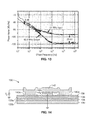
- FIG. 15 is a plot of frequency tuning response from a frequency divider utilizing the resonator of FIG. 14 , according to an embodiment of the present disclosure.
- the disclosure presents a frequency divider using a parametric amplification effect in a capacitive-gap/coupling/transducer transduced micro-electromechanical system (MEMS) device.
- MEMS micro-electromechanical system
- FIG. 1 illustrates an example embodiment 10 of a parametric divider showing 121-MHz pump signal v i 12 applied to the input electrodes and resultant 60.6-MHz signal on the output electrodes v o 14 .
- the resonator structure utilized in this parametric divider comprises an array of wine-glass disks resonators. Each disk structure has input electrodes 16 a , 16 b , and output electrodes 18 a , 18 b .
- a typical embodiment includes electrical inter-connection of electrodes disposed on opposing sides of the resonator, such as connecting 16 a to 16 b , and 18 a to 18 b .
- more general connection topologies may be utilized without departing from the teachings of this disclosure.
- the disk array contains multiple disks, illustrated here by way of example as three resonator structures 20 a , 20 b , 20 c coupled input-to-input.
- a voltage V P is seen applied 22 at an anchor 24 for controlling electrical stiffness in the disks 26 in resonators 20 a , 20 b , and 20 c .
- the anchors are electrically coupled across the array.
- the structure can be fabricated in conductive material, and the anchor need not be connected on the substrate, since the structure already makes contact from disk to disk.
- FIG. 2A and FIG. 2B depict input voltage waveform v i in FIG. 2A , and the respective output v o in FIG. 2B , for the device seen in FIG. 1 .
- FIG. 3A depicts the high-Q frequency response of the resonator as measured by two-port transmission with a network analyzer.
- the peak is seen at about 60.587 MHz.
- FIG. 3B depicts the mechanical mode-shape of a disk at peak resonance seen in FIG. 3A .
- FIG. 4 depicts resonance frequency tuning required for parametric amplification through an electrical stiffness effect with applied voltage V P .
- FIG. 5 illustrates an example embodiment 30 of a stand-alone differential-mode frequency divider used on a single disk 32 in order to boost divided output voltage swing and minimize common-mode harmonic feedthrough.
- these resonators can be arranged in an array format in similar manner as that shown in FIG. 1 .
- Out of phase electrodes 34 a , 34 b , and in-phase electrodes 36 a , 36 b are seen surrounding a floating (e.g., separated from the substrate) disk structure 38 which is only coupled about its periphery by anchors 40 connecting to the substrate.
- This example depicts an electrical connection 39 a between electrodes 34 a , 34 b , and a similar connection 39 b between electrodes 36 a , 36 b .
- resonator may be utilized with the present disclosure insofar as it includes a capacitive gap, or a capacitive coupling, or a capacitive transducer, or a combination thereof, for transduction or frequency tuning.
- the output signal is collected as voltage v oa 50 a from the in-phase connection 36 a , and voltage v ob 50 b from the out-of-phase connection 34 b .
- Each of these parametric oscillators operates in response to modulation of a frequency-determining parameter of a resonator, in this case electrical stiffness, at twice the resonance frequency. This produces an effect analogous to a child on a swing, where swinging legs modulate frequency (or stiffness), providing gain and enhancement of in-phase resonant motion that with sufficient pump strength drives the resonator into self-sustained oscillation.
- the single-ended version of FIG. 1 reduces phase noise by 6 dB at close-to-carrier frequencies and 23 dB far-from-carrier.
- the differential version of FIG. 5 enables an effective voltage gain, generating a measured output voltage swing of 450 mV pp , larger than the input swing of only 445 mV pp .
- the disclosed parametric oscillator requires no active devices, and thus, adds no additional noise sources beyond Brownian noise to the signal. Furthermore, since the power consumption fundamentally comprises only MEMS resonator loss, the power usage approaches zero. This MEMS divider can be expected to enable exceptionally low-power frequency synthesizers for applications where the operating frequency remains within the tuning range of the MEMS resonator, such as the chip-scale atomic clock (CSAC). Indeed, commercial CSACs presently consume a battery-unfriendly 120 mW, with a substantial portion of this power being consumed by the frequency dividers in their synthesizers.
- CSAC chip-scale atomic clock
- an applied pump modulates a frequency-determining “parameter”, realized here as the electrical stiffness k e , arising from the applied voltage across the electrode-disk capacitive gaps. This gives rise to the equations of motion:
- FIG. 6 depicts a theoretical representation 70 of the parametric oscillator divider consisting of a resonator (mass-spring-damper), having mass 72 , spring 74 and damper 76 , undergoing motion 78 at frequency ⁇ 0 .
- FIG. 7A and FIG. 7B are time domain plots of motion from which one can determine the frequency from the period.
- FIG. 7B depicts a stiffness k modulation curve, wherein restoring force is increased following X maxima and decreased near zero, leading to a parametric gain effect on motion.
- the lower bound of power required for this drive can, in principle, comprise only the energy transferred to the mechanical resonator.
- this power transfer need only be sufficient to balance resonator losses.
- this energy loss rate is very meager, requiring less than 100 nW to sustain full oscillation amplitude for the Q of 90 k at 61 MHz shown in the example embodiment here
- the MEMS resonators should possess both high operating frequency and the capability to accurately define multiple unique frequencies on the same die, for example their frequencies should be definable in the layout of the die (e.g., CAD layout of the die).
- the wine-glass disk resonators depicted in FIG. 1 and FIG. 5 are quite suitable, although the teachings herein are applicable to MEMS resonators having many other structures.
- the embodied devices comprise 2 ⁇ m-thick, 32 ⁇ m-radius polysilicon disks supported by beams at quasi-nodal points and coupled along their sidewalls to input-output electrodes by tiny 40 nm capacitive gaps.
- coupling beams sized to correspond to half the acoustic wavelength, force the individual resonators to move in-phase at a single resonance, allowing output current to add constructively to boost electromechanical coupling by the number of individual resonators.
- a bias voltage V P on the disk structure combines with an AC drive voltage applied to all input electrodes to produce forces across the input electrode-to-resonator gaps (or capacitive coupling or capacitive transducer) that, at resonance, excite the wine-glass (i.e., compound (2, 1)) mode shape, shown in FIG. 3B .
- the frequency of resonance is given by:
- the lateral capacitive gap, exemplified as 40 nm, of the device seen in FIG. 1 produces both the strong voltage-dependent frequency tuning, such as seen in FIG. 3A , required for parametric excitation, and with an applied bias voltage, produce an output current proportional to the resonator motion.
- the small capacitive gaps or capacitive coupling or capacitive transducer
- the small capacitive gaps enable parametric oscillation at UHF frequencies well beyond the kHz range of earlier parametrically amplified sensors, and further allow adjustment of the operating frequency of the divider, as needed for many real-world applications.
- the MEMS resonator Because of a high mechanical Q value, the MEMS resonator responds with long time constants to changes in the input signal, which in effect filters out noise signals not within its bandwidth. This means that when operated as a self-sustained parametric oscillator, this device removes oscillation perturbations at frequencies greater than the bandwidth of the resonator.
- the extremely high Q-factor of the MEMS resonator deployed within embodiments described herein produce a pronounced filter cut-off even at frequency offsets below 1 kHz.
- the MEMS-based parametric oscillator provides not only divide-by-two frequency division with the expected 6 dB phase noise reduction, but also additional filtering of phase noise outside of the resonator bandwidth. It should be noted that while an effective narrow lock range of the oscillator provides additional filtering, the operating frequency can still be tuned over a much larger range through use of the voltage-controllable electrical stiffness, allowing this device to operate over appreciable bandwidths.
- FIG. 8A through FIG. 8D illustrate an example embodiment 90 of a disk resonator fabrication process consisting of repeated thin-film polysilicon and oxide deposition and etching on a silicon substrate.
- the example fabrication process used for these devices was based on a surface micromachining process summarized in these cross sections.
- FIG. 8A there is seen a silicon substrate 92 with its oxide layer 94 .
- a layer of nitride 96 is deposited over the silicon oxide followed by a masked interconnect layer, such as of polysilicon, the interconnect is in layer segments 98 a , 98 b . Over the interconnect layer is formed a sacrificial oxide layer 100 . This first step of FIG. 8A thus indicates achieving an electrical interconnect.
- FIG. 8B subsequent depositions and etching yields a structure layer 102 covered by oxide 104 and a sidewall layer 106 (e.g., 40 nm) covering these elements and over the remaining portion 100 ′ of sacrificial oxide.
- CMP Chemical-Mechanical Polishing
- a wet-etch such as in 49% HF, yields the released resonator structure of FIG. 8D .
- sacrificial oxide region 100 ′ has been removed to create a void area 100 ′′ thus freeing the underside of the disk.
- the sidewall material 106 has been removed leaving a gap 110 freeing the perimeter of the disk 112 . It should be appreciated that although the anchors are formed in this process, they are not visible from this cross-section view.
- the devices and electrical interconnect were fabricated from polysilicon deposited utilizing Low-Pressure Chemical-Vapor Deposition (LPCVD) at 615° C., in-situ doped with phosphorus.
- LPCVD Low-Pressure Chemical-Vapor Deposition
- a High-Temperature Oxide (HTO) deposition provided the high-quality sacrificial sidewall spacer that enabled 40 nm electrode-to-resonator gaps.
- Two CMP steps, one before structural polysilicon deposition and patterning and the other after the electrode polysilicon deposition, provided the planar surfaces needed for precise lithography, as well as removed electrode-disk overhangs that can cause pull-in and device failure at low bias voltages.
- FIG. 9 and FIG. 10 illustrates example implementations of released frequency-dividers, similar to that depicted in FIG. 8A through FIG. 8D , shown as scanning electron microscope images (SEMs) along with an inset of FEM simulations depicting oscillation resonance mode shapes.
- SEMs scanning electron microscope images
- FIG. 9 the SEM image depicts a single-disk differential device
- FIG. 10 the SEM image depicts a 3-disk arrayed single-ended divider.
- FIG. 11 depicts an input at 121.174 MHz pump waveform (higher amplitude signal) and a resultant 60.587 MHz output waveform measured on the single-ended divider (three disk element array) of a device as seen in FIG. 1 , and shown implemented in FIG. 9 .
- Input and output signals spanned 700 mV pp and 265 mV pp , respectively. The distortion seen in these waveforms result from feedthrough of the pump signal.
- the resultant 60.587-MHz oscillation combined with a 4 V bias voltage generates a current at the output electrode that drives the modestly large 350 fF output capacitance (composed of bond pad plus Picoprobe capacitance) to a 265 mV pp swing. While the output-to-input voltage ratio is below unity in this configuration due to the large output capacitance, the generated output current would be sufficient to produce an output voltage swing equivalent to input when driving the much smaller 50 fF capacitance of an integrated second MEMS division stage or on-chip buffer.
- FIG. 12A through FIG. 12C depict waveforms from a single-disk differential measurement, showing a 445 mV pp input pump signal in FIG. 12A , separate differential outputs in FIG. 12B , and a combined differential output of 450 mV pp in FIG. 12C .
- the resultant output swing seen in FIG. 12C spans 450 mV pp using only a 445 mV pp pump.
- voltage gain is provided, as needed for a cascaded divider chain, without need for power-hungry active devices.
- FIG. 13 depicts a single side-band phase noise comparison of input pump signal from a low quality voltage controlled oscillator (VCO) operating at 121.2 MHz and resultant 60.6 MHz output of the single-ended divider when driven by a custom-built VCO.
- Phase noise in the figure shows a typical 6 dB improvement at low frequency.
- the high-Q resonator response provides filtering of noise past a 1 kHz offset, leading to a remarkable 23 dB decrease in far-from-carrier phase noise, limited only by the poor 50 nV/rtHz, (rtHz indicating square-root of frequency in Hertz) noise performance of the Picoprobe used to measure the output.
- this MEMS-based approach further offers significant space savings over similar CMOS based dividers, where bulky inductors consume 750 ⁇ m ⁇ 320 ⁇ m for an operating frequency of 20 GHz, and offer no possibility of division down to typical reference frequencies, e.g., 10 MHz.
- this MEMS-based frequency divider shrinks in size.
- a 3.4 GHz version would occupy under 30 ⁇ m ⁇ 30 ⁇ m of die area. Future efforts to design frequency-matched chains of such MEMS dividers would be expected to enable complete low-power PLL topologies at up into GHz frequencies.
- this device adds a previously missing frequency divider capability to the MEMS toolbox.
- the frequency range of the present disclosure can be widened utilizing any of several different methods.
- One such method is that of adjusting DC bias voltage.
- the applied voltage consists of two components.
- a first component is an AC modulating bias voltage that gives rise to parametric gain used here for the frequency dividing effect.
- a second component is a DC bias component that sets the output current, but also sets the center frequency of the device.
- the central frequency tuning range can be several percent.
- FIG. 14 illustrates another form of example resonator 130 , depicted as a beam resonator, which demonstrates a 1.1% tuning range at 32 MHz. It should be appreciated, by contrast, that certain comb driven resonators can be pulled over 10%.
- the beam resonator illustrated is seen fabricated over layers comprising a substrate 132 , with several oxide isolation layers 134 , 135 a , 135 b and 136 , and a silicon nitride layer 138 .
- Beam 142 is anchored at 140 a , and resonates in relation to electrode 140 b . This figure illustrates that many other forms of MEMS resonators may be used.
- FIG. 15 depicts the frequency tuning response of the beam resonator device.
- resonators both contour mode or others, such as wine-glass ring
- Lame mode resonators bar resonators
- flexural beam resonators membrane or “drum head” resonators
- comb-driven flexural-mode resonators with suitable tuning electrodes center-supported disk resonators (e.g., using both in-plane contour, and whispering gallery modes, or various flexural mode operation)
- surface acoustic wave (SAW) devices bulk acoustic wave (BAW) devices
- FBAR film bulk acoustic resonator
- LOBAR lateral overmoded bulk acoustic-wave resonator
- internal dielectric actuated resonators may be utilized in any of the above mode shapes, where the needed capacitive coupling is provided by the internal dielectric gap.
- internally-transduced resonators may be utilized in which the capacitive-gap is formed from a semiconductor junction, as in body-resonator transistors.
- the disclosed teachings may be utilized with various combinations of the above devices without departing from the these disclosed teachings.
- a micro-electromechanical system (MEMS) frequency divider apparatus comprising: (a) a substrate; (b) at least one MEMS resonator disposed on the substrate, said resonator having a resonant structure configured for mechanical oscillation at a resonance frequency ⁇ 0 ; and (c) one or more electrodes, disposed on said substrate, or MEMS resonator, that are capacitively coupled to one or more portions of said resonant structure; (d) an input AC voltage coupled to said resonant structure, with frequency at an approximate multiple of said resonance frequency ⁇ 0 , that induces mechanical oscillation of said resonant structure to generate an output whose frequency is a division of said input frequency.
- MEMS micro-electromechanical system
- said division of said input frequency comprises a divide-by-two, so that the output frequency from said apparatus is one-half of said input frequency.
- said mechanical coupling comprises material, disposed in separation from said substrate, while connecting from the resonant structure in one MEMS resonator to the resonant structure of a subsequent MEMS resonator.
- At least one drive electrode is disposed on said substrate, or MEMS resonator, which is capacitively coupled to said resonant structure of a first MEMS resonator for driving this first MEMS resonator into mechanical oscillation, which is mechanically carried through consecutively coupled MEMS resonators in the array divider.
- said at least one MEMS resonator comprises either a single MEMS resonator, or multiple MEMS resonators with their resonant structures mechanically coupled to one another in an array configuration.
- said resonant structure of said MEMS resonator comprises a disk resonator, having a central disk surrounded by multiple electrodes retained in close proximity to said central disk.
- said MEMS resonator comprises a wine glass disk resonator.
- said MEMS resonator is a MEMS resonator which utilizes a capacitive gap for transduction.
- said MEMS resonator is selected from a group of resonators consisting of comb-driven resonators, piezo coupled resonators, ring resonators, contour mode ring resonators, wine-glass ring resonators, Lame mode resonators, bar resonators, flexural beam resonators, membrane resonators, comb-driven flexural-mode resonators, center-supported disk resonators, surface acoustic wave (SAW) devices, bulk acoustic wave (BAW) devices, film bulk acoustic resonator (FBAR) devices, lateral overmoded bulk acoustic-wave resonator (LOBAR) devices, piezo actuated resonators, internal dielectric actuated resonators, internally-transduced resonators having a capacitive-coupling formed from a semiconductor junction, and combinations thereof.
- SAW surface acoustic wave
- BAW bulk acou
- a micro-electromechanical system (MEMS) frequency divider apparatus comprising: (a) a substrate; (b) a first MEMS resonator disposed above the substrate, the MEMS resonator comprising a resonant structure configured for mechanical oscillation at a resonance frequency ⁇ 0 ; (c) one or more electrodes, disposed on said substrate, or MEMS resonator, which are capacitively coupled to one or more portions of said resonant structure of said first MEMS resonator; and (d) at least one additional MEMS parametric oscillator comprising a resonant structure configured for mechanical oscillation at a resonance frequency ⁇ 0 ; (e) wherein said first MEMS resonator and the additional MEMS resonators comprise a divider array with mechanical linkages disposed in separation from said substrate, between said first MEMS resonator and the additional MEMS resonators, whereby vibrations of the first and additional MEMS resonators are mechanically coupled; and (f) where
- MEMS resonator is a MEMS resonator which utilizes a capacitive gap for transduction.
- said MEMS resonator is selected from a group of resonators consisting of comb-driven resonators, piezo coupled resonators, ring resonators, contour mode ring resonators, wine-glass ring resonators, Lame mode resonators, bar resonators, flexural beam resonators, membrane resonators, comb-driven flexural-mode resonators, center-supported disk resonators, surface acoustic wave (SAW) devices, bulk acoustic wave (BAW) devices, film bulk acoustic resonator (FBAR) devices, lateral overmoded bulk acoustic-wave resonator (LOBAR) devices, piezo actuated resonators, internal dielectric actuated resonators, internally-transduced resonators having a capacitive-coupling formed from a semiconductor junction, and combinations thereof.
- SAW surface acoustic wave
- BAW bulk acou
- a method of performing frequency division comprising: (a) inducing mechanical vibration of a micro-electromechanical system (MEMS) resonator in response to capacitively coupling a drive signal at a first frequency, from a proximal electrode to a resonant structure in said MEMS resonator; (b) wherein said first frequency is approximately a multiple of a resonant frequency of the MEMS resonator; (c) carrying mechanical vibration to another portion of said resonant structure in said MEMS resonator, or to one or more additional MEMS resonators mechanically coupled thereto; and (d) outputting a second frequency, as a division of said first frequency, in response to capacitive coupling from said resonant structure of said MEMS resonator, or one of said additional MEMS resonators mechanically coupled thereto, to one or more proximally disposed electrodes.
- MEMS micro-electromechanical system
Landscapes
- Physics & Mathematics (AREA)
- Acoustics & Sound (AREA)
- Engineering & Computer Science (AREA)
- Power Engineering (AREA)
- Micromachines (AREA)
- Piezo-Electric Or Mechanical Vibrators, Or Delay Or Filter Circuits (AREA)
Priority Applications (1)
| Application Number | Priority Date | Filing Date | Title |
|---|---|---|---|
| US15/170,577 US10224875B2 (en) | 2013-12-02 | 2016-06-01 | Micromechanical frequency divider |
Applications Claiming Priority (3)
| Application Number | Priority Date | Filing Date | Title |
|---|---|---|---|
| US201361910916P | 2013-12-02 | 2013-12-02 | |
| PCT/US2014/068209 WO2015126498A2 (fr) | 2013-12-02 | 2014-12-02 | Diviseur de fréquence micromécanique |
| US15/170,577 US10224875B2 (en) | 2013-12-02 | 2016-06-01 | Micromechanical frequency divider |
Related Parent Applications (1)
| Application Number | Title | Priority Date | Filing Date |
|---|---|---|---|
| PCT/US2014/068209 Continuation WO2015126498A2 (fr) | 2013-12-02 | 2014-12-02 | Diviseur de fréquence micromécanique |
Publications (2)
| Publication Number | Publication Date |
|---|---|
| US20170047893A1 US20170047893A1 (en) | 2017-02-16 |
| US10224875B2 true US10224875B2 (en) | 2019-03-05 |
Family
ID=53879212
Family Applications (1)
| Application Number | Title | Priority Date | Filing Date |
|---|---|---|---|
| US15/170,577 Active 2035-05-24 US10224875B2 (en) | 2013-12-02 | 2016-06-01 | Micromechanical frequency divider |
Country Status (2)
| Country | Link |
|---|---|
| US (1) | US10224875B2 (fr) |
| WO (1) | WO2015126498A2 (fr) |
Cited By (1)
| Publication number | Priority date | Publication date | Assignee | Title |
|---|---|---|---|---|
| US20220163413A1 (en) * | 2019-06-07 | 2022-05-26 | The Regents Of The University Of California | Electrical stiffness-based sensor |
Families Citing this family (16)
| Publication number | Priority date | Publication date | Assignee | Title |
|---|---|---|---|---|
| US9716485B2 (en) * | 2014-06-08 | 2017-07-25 | Board Of Trustees Of Michigan State University | Frequency divider apparatus |
| US11097312B2 (en) * | 2015-08-11 | 2021-08-24 | Koninklijke Philips N.V. | Capacitive micromachined ultrasonic transducers with increased lifetime |
| CN110546890B (zh) | 2017-02-11 | 2021-09-21 | 穆麦克股份有限公司 | 具有改善频率区分的超再生收发器 |
| CN107655595B (zh) * | 2017-10-19 | 2020-01-14 | 机械工业仪器仪表综合技术经济研究所 | 微机电谐振结构、谐振器及压力传感器 |
| JP7074605B2 (ja) * | 2018-08-01 | 2022-05-24 | 株式会社東芝 | Memsデバイス |
| EP3699610B1 (fr) * | 2019-02-22 | 2023-04-19 | NXP USA, Inc. | Circuit d'interface capacitance-tension |
| US11988727B1 (en) | 2019-07-31 | 2024-05-21 | Hrl Laboratories, Llc | Magnetostrictive MEMS magnetic gradiometer |
| US11567147B1 (en) | 2019-07-31 | 2023-01-31 | Hrl Laboratories, Llc | Phononic comb enhanced gradiometers |
| US11747512B1 (en) | 2019-08-23 | 2023-09-05 | Hrl Laboratories, Llc | Phononic comb enhanced MEMS gravity gradiometers |
| US11431293B1 (en) * | 2020-09-25 | 2022-08-30 | Hrl Laboratories, Llc | Noise suppression in a phononic comb |
| CN112953435B (zh) * | 2021-01-13 | 2023-06-20 | 西安交通大学 | 一种基于参数泵的mems振荡器 |
| US11863194B1 (en) | 2021-02-02 | 2024-01-02 | Hrl Laboratories, Llc | Phononic comb enhanced atomic clock |
| US11606098B1 (en) | 2021-02-23 | 2023-03-14 | Hrl Laboratories, Llc | Comb enhanced oscillator with AM-to-PM noise suppression |
| US12483224B1 (en) | 2021-07-16 | 2025-11-25 | Hrl Laboratories, Llc | Acoustically coupled dual resonators for phononic frequency comb generation |
| US12160240B2 (en) | 2022-07-29 | 2024-12-03 | Hrl Laboratories, Llc | Method and system for generating phononic frequency comb |
| US12191867B1 (en) | 2022-09-08 | 2025-01-07 | Hrl Laboratories, Llc | In-situ phase noise compensation for phononic frequency combs |
Citations (6)
| Publication number | Priority date | Publication date | Assignee | Title |
|---|---|---|---|---|
| US20030151446A1 (en) * | 2002-02-14 | 2003-08-14 | Datum,Inc. | Mems analog frequency divider |
| US7023065B2 (en) | 2002-08-07 | 2006-04-04 | Georgia Tech Research Corporation | Capacitive resonators and methods of fabrication |
| US7369004B2 (en) * | 2006-06-14 | 2008-05-06 | Sitime, Corporation | Microelectromechanical oscillator and method of operating same |
| US7551043B2 (en) | 2005-08-29 | 2009-06-23 | The Regents Of The University Of Michigan | Micromechanical structures having a capacitive transducer gap filled with a dielectric and method of making same |
| US20090206963A1 (en) | 2008-02-15 | 2009-08-20 | Toyota Motor Engineering & Manufacturing North America, Inc. | Tunable metamaterials using microelectromechanical structures |
| US20100271088A1 (en) | 2007-11-14 | 2010-10-28 | Panasonic Corporation | Synthesizer, synthesizer module, and reception device and electronic device using same |
-
2014
- 2014-12-02 WO PCT/US2014/068209 patent/WO2015126498A2/fr not_active Ceased
-
2016
- 2016-06-01 US US15/170,577 patent/US10224875B2/en active Active
Patent Citations (6)
| Publication number | Priority date | Publication date | Assignee | Title |
|---|---|---|---|---|
| US20030151446A1 (en) * | 2002-02-14 | 2003-08-14 | Datum,Inc. | Mems analog frequency divider |
| US7023065B2 (en) | 2002-08-07 | 2006-04-04 | Georgia Tech Research Corporation | Capacitive resonators and methods of fabrication |
| US7551043B2 (en) | 2005-08-29 | 2009-06-23 | The Regents Of The University Of Michigan | Micromechanical structures having a capacitive transducer gap filled with a dielectric and method of making same |
| US7369004B2 (en) * | 2006-06-14 | 2008-05-06 | Sitime, Corporation | Microelectromechanical oscillator and method of operating same |
| US20100271088A1 (en) | 2007-11-14 | 2010-10-28 | Panasonic Corporation | Synthesizer, synthesizer module, and reception device and electronic device using same |
| US20090206963A1 (en) | 2008-02-15 | 2009-08-20 | Toyota Motor Engineering & Manufacturing North America, Inc. | Tunable metamaterials using microelectromechanical structures |
Non-Patent Citations (1)
| Title |
|---|
| Korean Intellectual Property Organization (KIPO), International Search Report and Written Opinion, PCT/US2014/068209, dated Sep. 14, 2015, pp. 1-14, with claims searched, pp. 15-28. |
Cited By (2)
| Publication number | Priority date | Publication date | Assignee | Title |
|---|---|---|---|---|
| US20220163413A1 (en) * | 2019-06-07 | 2022-05-26 | The Regents Of The University Of California | Electrical stiffness-based sensor |
| US12235173B2 (en) * | 2019-06-07 | 2025-02-25 | The Regents Of The University Of California | Electrical stiffness-based sensor |
Also Published As
| Publication number | Publication date |
|---|---|
| US20170047893A1 (en) | 2017-02-16 |
| WO2015126498A2 (fr) | 2015-08-27 |
| WO2015126498A3 (fr) | 2015-11-05 |
Similar Documents
| Publication | Publication Date | Title |
|---|---|---|
| US10224875B2 (en) | Micromechanical frequency divider | |
| US20250264773A1 (en) | Piezoelectric resonant-based mechanical frequency combs | |
| US7724103B2 (en) | Ultra-high frequency self-sustaining oscillators, coupled oscillators, voltage-controlled oscillators, and oscillator arrays based on vibrating nanoelectromechanical resonators | |
| US7511870B2 (en) | Highly tunable low-impedance capacitive micromechanical resonators, oscillators, and processes relating thereto | |
| EP3210303B1 (fr) | Résonateur mems avec un paquet de ressorts pour la génération des signaux d'horloge et pour commander la fréquence d'un system oscillateur | |
| US6958566B2 (en) | Mechanical resonator device having phenomena-dependent electrical stiffness | |
| Weinstein et al. | Internal dielectric transduction in bulk-mode resonators | |
| Lee et al. | A single-crystal-silicon bulk-acoustic-mode microresonator oscillator | |
| US7911296B2 (en) | Resonator system such as a microresonator system and method of making same | |
| JP4728242B2 (ja) | 捩り共振器およびこれを用いたフィルタ | |
| US9866200B2 (en) | Multiple coil spring MEMS resonator | |
| Verd et al. | A 3V CMOS-MEMS oscillator in 0.35 μm CMOS technology | |
| Rawat et al. | Piezoelectric-on-Silicon array resonators with asymmetric phononic crystal tethering | |
| US11533042B2 (en) | Distributed-mode beam and frame resonators for high frequency timing circuits | |
| Park et al. | Phononic frequency combs in stand-alone piezoelectric resonators | |
| Moghadam et al. | Design and analysis of a torsional mode MEMS disk resonator for RF applications | |
| Akgul et al. | Oscillator far-from-carrier phase noise reduction via nano-scale gap tuning of micromechanical resonators | |
| CN100517964C (zh) | 微振子、半导体装置以及通信装置 | |
| Rinaldi et al. | High power and low temperature coefficient of frequency oscillator based on a fully anchored and oxide compensated AlN contour-mode MEMS resonator | |
| Rocheleau et al. | A micromechanical parametric oscillator for frequency division and phase noise reduction | |
| Wu et al. | A novel narrowband MEMS filter with extensional mode resonators | |
| Wu et al. | A high-performance bulk mode single crystal silicon microresonator based on a cavity-SOI wafer | |
| Iqbal et al. | Piezoresistive sensing in a SOI mechanically coupled micromechanical multiple-resonator array | |
| Tallur et al. | Monolithic 2GHz electrostatically actuated MEMS oscillator with opto-mechanical frequency multiplier | |
| Lin et al. | Quality factor enhancement in Lamb wave resonators utilizing AlN plates with convex edges |
Legal Events
| Date | Code | Title | Description |
|---|---|---|---|
| AS | Assignment |
Owner name: THE REGENTS OF THE UNIVERSITY OF CALIFORNIA, CALIF Free format text: ASSIGNMENT OF ASSIGNORS INTEREST;ASSIGNORS:NGUYEN, CLARK T.-C.;ROCHELEAU, TRISTAN O.;SIGNING DATES FROM 20160808 TO 20160819;REEL/FRAME:039494/0447 |
|
| STCF | Information on status: patent grant |
Free format text: PATENTED CASE |
|
| MAFP | Maintenance fee payment |
Free format text: PAYMENT OF MAINTENANCE FEE, 4TH YR, SMALL ENTITY (ORIGINAL EVENT CODE: M2551); ENTITY STATUS OF PATENT OWNER: SMALL ENTITY Year of fee payment: 4 |