US10378387B2 - CMC shroud support system of a gas turbine - Google Patents
CMC shroud support system of a gas turbine Download PDFInfo
- Publication number
- US10378387B2 US10378387B2 US14/891,806 US201414891806A US10378387B2 US 10378387 B2 US10378387 B2 US 10378387B2 US 201414891806 A US201414891806 A US 201414891806A US 10378387 B2 US10378387 B2 US 10378387B2
- Authority
- US
- United States
- Prior art keywords
- shroud
- wall
- retainer
- hanger
- support system
- Prior art date
- Legal status (The legal status is an assumption and is not a legal conclusion. Google has not performed a legal analysis and makes no representation as to the accuracy of the status listed.)
- Active, expires
Links
Images


Classifications
-
- F—MECHANICAL ENGINEERING; LIGHTING; HEATING; WEAPONS; BLASTING
- F01—MACHINES OR ENGINES IN GENERAL; ENGINE PLANTS IN GENERAL; STEAM ENGINES
- F01D—NON-POSITIVE DISPLACEMENT MACHINES OR ENGINES, e.g. STEAM TURBINES
- F01D25/00—Component parts, details, or accessories, not provided for in, or of interest apart from, other groups
- F01D25/28—Supporting or mounting arrangements, e.g. for turbine casing
-
- F—MECHANICAL ENGINEERING; LIGHTING; HEATING; WEAPONS; BLASTING
- F01—MACHINES OR ENGINES IN GENERAL; ENGINE PLANTS IN GENERAL; STEAM ENGINES
- F01D—NON-POSITIVE DISPLACEMENT MACHINES OR ENGINES, e.g. STEAM TURBINES
- F01D11/00—Preventing or minimising internal leakage of working-fluid, e.g. between stages
- F01D11/08—Preventing or minimising internal leakage of working-fluid, e.g. between stages for sealing space between rotor blade tips and stator
- F01D11/12—Preventing or minimising internal leakage of working-fluid, e.g. between stages for sealing space between rotor blade tips and stator using a rubstrip, e.g. erodible. deformable or resiliently-biased part
-
- F—MECHANICAL ENGINEERING; LIGHTING; HEATING; WEAPONS; BLASTING
- F01—MACHINES OR ENGINES IN GENERAL; ENGINE PLANTS IN GENERAL; STEAM ENGINES
- F01D—NON-POSITIVE DISPLACEMENT MACHINES OR ENGINES, e.g. STEAM TURBINES
- F01D25/00—Component parts, details, or accessories, not provided for in, or of interest apart from, other groups
- F01D25/24—Casings; Casing parts, e.g. diaphragms, casing fastenings
- F01D25/246—Fastening of diaphragms or stator-rings
-
- F—MECHANICAL ENGINEERING; LIGHTING; HEATING; WEAPONS; BLASTING
- F05—INDEXING SCHEMES RELATING TO ENGINES OR PUMPS IN VARIOUS SUBCLASSES OF CLASSES F01-F04
- F05D—INDEXING SCHEME FOR ASPECTS RELATING TO NON-POSITIVE-DISPLACEMENT MACHINES OR ENGINES, GAS-TURBINES OR JET-PROPULSION PLANTS
- F05D2300/00—Materials; Properties thereof
- F05D2300/60—Properties or characteristics given to material by treatment or manufacturing
- F05D2300/603—Composites; e.g. fibre-reinforced
- F05D2300/6033—Ceramic matrix composites [CMC]
-
- Y—GENERAL TAGGING OF NEW TECHNOLOGICAL DEVELOPMENTS; GENERAL TAGGING OF CROSS-SECTIONAL TECHNOLOGIES SPANNING OVER SEVERAL SECTIONS OF THE IPC; TECHNICAL SUBJECTS COVERED BY FORMER USPC CROSS-REFERENCE ART COLLECTIONS [XRACs] AND DIGESTS
- Y02—TECHNOLOGIES OR APPLICATIONS FOR MITIGATION OR ADAPTATION AGAINST CLIMATE CHANGE
- Y02T—CLIMATE CHANGE MITIGATION TECHNOLOGIES RELATED TO TRANSPORTATION
- Y02T50/00—Aeronautics or air transport
- Y02T50/60—Efficient propulsion technologies, e.g. for aircraft
-
- Y02T50/672—
Definitions
- Embodiments of the invention relate to shrouds for a gas turbine engines. More particularly, but not by way of limitation, present embodiments relate to ceramic matrix composite shroud support systems utilized in gas turbine engines.
- a typical gas turbine engine generally possesses a forward end and an aft end with its several core or propulsion components positioned axially therebetween.
- An air inlet or intake is located at a forward end of the engine. Moving toward the aft end, in order, the intake is followed by a compressor, a combustion chamber, and a turbine.
- additional components may also be included in the engine, such as, for example, low-pressure and high-pressure compressors, and low-pressure and high-pressure turbines. This, however, is not an exhaustive list.
- An engine also typically has an internal shaft axially disposed along a center longitudinal axis of the engine. The internal shaft is connected to both the turbine and the air compressor, such that the turbine provides a rotational input to the air compressor to drive the compressor blades.
- a high pressure turbine first receives the hot combustion gases from the combustor and includes a stator nozzle assembly directing the combustion gases downstream through a row of high pressure turbine rotor blades extending radially outwardly from a supporting rotor disk.
- a second stage stator nozzle assembly is positioned downstream of the first stage blades followed in turn by a row of second stage rotor blades extending radially outwardly from a second supporting rotor disk. The turbine converts the combustion gas energy to mechanical energy.
- Each of the turbines may include one or more stages of rotor blades which extend radially outward from rotor discs.
- a shroud assembly circumscribes the turbine rotor and defines an outer boundary for combustion gases flowing through the turbine.
- the turbine shroud may be a single unitary structure or may be formed of a plurality of segments.
- Some known shroud assemblies include a shroud hanger that is coupled to an outer casing of the engine to provide support to a plurality of shrouds positioned adjacent to, and radially outward of, the tips of the turbine blades.
- the shrouds may be coupled by way of a single bolted connection to the shroud hanger. However, should a crack or bolt failure occur, the shroud may become disconnected from the shroud hanger.
- the shroud must be capable of meeting the design life requirements for use in the turbine engine operating temperature and pressure environment.
- CMC ceramic matrix composite
- CMC ceramic matrix composite
- Such ceramic matrix composite (CMC) materials have mechanical properties that must be considered during the design and application of the CMC use as a shroud segment or component.
- CMC materials have relatively low tensile ductility or low strain to failure when compared to metallic materials.
- CMC materials have a coefficient of thermal expansion which differs significantly from metal alloys used as restraining supports or hangers for shrouds of CMC type materials. Therefore, if a CMC shroud segment is restrained and cooled on one surface during operation, stress concentrations can develop leading to failure of the segment.
- a shroud support system with load spreading comprises a shroud hanger which extends in at least a circumferential direction, the shroud hanger having a first wall and a second wall spaced apart in an axial direction by a retainer support wall, a ceramic matrix composite shroud disposed in the shroud hanger between the first and second walls and the retainer support wall, a retainer having circumferentially spaced first and second bolt holes, the retainer passing through the shroud, and first and second bolts passing through the shroud hanger and engaging the first and second bolt holes of the retainer.
- the shroud hanger has first and second bolt holes, the first and second bolt holes being spaced circumferentially. In another embodiment of the shroud support system, the first and second bolt holes of the shroud hanger extending one of parallel or at an angle relative to each other through the shroud hanger. In another embodiment, the shroud support system further comprises plural bosses depending from the retainer support wall. In another embodiment, the shroud support system further comprises a shroud hanger bolt hole in each boss. In another embodiment of the shroud support system, the shroud is disposed between first and second bosses. In another embodiment, the shroud support system further comprises air diffuser cavity holes in the shroud hanger.
- one of the first and second walls function as a spring.
- the retainer has a plurality of protrusions to engage the shroud.
- the shroud support system further comprises a baffle disposed below the retainer and within the shroud hanger.
- FIG. 1 is a side section view of a gas turbine engine
- FIG. 2 is a side section view of an assembled exemplary turbine shroud support section system
- FIG. 3 is an exploded isometric view of an exemplary shroud support system
- FIG. 4 is an aft-looking-forward section view of an exemplary shroud support system
- FIG. 5 is a detail section depicting one bolted connection of the shroud support system
- FIG. 6 is lower isometric view of a shroud hanger of the exemplary shroud support system
- FIG. 7 is an isometric view of an exemplary shroud
- FIG. 8 is an isometric view of a retainer
- FIG. 9 is an isometric view of a baffle utilized with the shroud support system.
- CMC Ceramic Matrix Composite
- the shroud hanger support system may be utilized in various portions of the gas turbine engine including, but not limited to, high pressure and low pressure turbines as well as the compressor.
- the hanger support system includes a load spreading retainer and redundant couplings to retain the system together. All of these features improve any or all of manufacture, operation or performance.
- axial refers to a dimension along a longitudinal axis of an engine.
- forward used in conjunction with “axial” or “axially” refers to moving in a direction toward the engine inlet, or a component being relatively closer to the engine inlet as compared to another component.
- aft used in conjunction with “axial” or “axially” refers to moving in a direction toward the engine nozzle, or a component being relatively closer to the engine nozzle as compared to another component.
- the terms “radial” or “radially” refer to a dimension extending between a center longitudinal axis of the engine and an outer engine circumference.
- proximal or “proximally,” either by themselves or in conjunction with the terms “radial” or “radially,” refers to moving in a direction toward the center longitudinal axis, or a component being relatively closer to the center longitudinal axis as compared to another component.
- distal or disally, either by themselves or in conjunction with the terms “radial” or “radially,” refers to moving in a direction toward the outer engine circumference, or a component being relatively closer to the outer engine circumference as compared to another component.
- lateral refers to a dimension that is perpendicular to both the axial and radial dimensions.
- FIG. 1 a schematic side section view of a gas turbine engine 10 is shown.
- the function of the turbine is to extract energy from high pressure and temperature combustion gases and convert the energy into mechanical energy for work.
- the gas turbine engine 10 has an engine inlet end 12 wherein air enters the core or propulsor 13 which is defined generally by a compressor 14 , a combustor 16 , and a multi-stage high pressure turbine 20 . Collectively, the propulsor 13 provides during operation.
- the gas turbine engine 10 may be used for aviation, power generation, industrial, marine or the like.
- the compressed air is mixed with fuel and burned providing the hot combustion gas which exits the combustor 16 toward the high pressure turbine 20 .
- energy is extracted from the hot combustion gas causing rotation of turbine blades which in turn cause rotation of the shaft 24 .
- the shaft 24 passes toward the front of the engine to continue rotation of the one or more compressor stages 14 , a turbofan 18 or inlet fan blades, depending on the turbine design.
- the turbofan 18 is connected by the shaft 28 to a low pressure turbine 21 and creates thrust for the turbine engine 10 .
- the low pressure turbine 21 may also be utilized to extract further energy and power additional compressor stages.
- the low pressure air may be used to aid in cooling components of the engine as well.
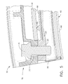
- FIG. 2 a side section view of exemplary shroud support system 30 is depicted.
- An exemplary turbine is shown, however the instant embodiments are not limited to turbine use.
- the turbine 20 includes a row of circumferentially spaced stationary vanes (not shown) and a plurality of circumferentially spaced turbine blades 23 downstream of the vanes.
- the blades 23 are foil-shaped and mounted to a turbine rotor disk (not shown).
- Each of the blades 23 extends radially toward a shroud 40 .
- the shroud 40 extends circumferentially about the engine axis 26 and is comprised of a plurality of shroud segments 41 ( FIG. 3 ).
- the shroud 40 may be formed of one unitary structure.
- the shroud 40 is tightly configured relative to the blades 23 so that the shroud 40 defines an outer radial flowpath boundary for the hot combustion gas flowing through the turbine 20 .
- the system 30 includes a hanger 70 , a shroud 40 comprised of a plurality of shroud segments 41 and a retainer 80 .
- a baffle 90 may optionally be used within the shroud segment 41 and beneath the retainer 80 .
- the system 30 includes a shroud hanger 70 which is connected to an engine casing 35 and extends circumferentially about a portion of the engine, for example the turbine.
- the engine casing 35 extends circumferentially about the engine axis 26 ( FIG. 1 ).
- Hangers 70 are extending from the radially inward side of the engine casing.
- the hangers 70 retain the shroud segments 41 in circular configuration about the engine axis 26 ( FIG. 1 ) and the shroud segments 41 define the flow boundary within portions of the engine, for non-limiting example, the compressor 14 or turbine 20 .
- the shroud hanger 70 is defined by a plurality of segments which in combination, extend about the central axis 26 of the engine.
- the shroud hanger 70 includes a first wall 72 a second wall 74 , each of which extend in a radial direction and in a circumferential direction.
- a hanger gusset 76 extends between the first wall 72 and the second wall 74 and may extend axially or may extend at an angle to the central axis 26 as depicted. According to instant embodiment, the gusset 76 is tapered from a lower radial height at the first wall 72 to a higher radial height at the second wall 74 .
- the shroud hanger 70 includes tabs or hooks 73 , 75 which may be utilized to engage the engine casing.
- the gusset 76 may alternatively be flat or tapered in the opposite direction. These hooks 73 , 75 may take various forms in order to provide a mounting assembly or structure.
- the shroud hanger 70 has a space between the first wall 72 and the second wall 74 wherein the shroud segment 41 may be positioned.
- the lower most surface of the shroud segment 41 defines an outer surface of an air flow path within the gas turbine engine, for example a compressor or turbine.
- the segments 41 may further comprise an abradable material 43 on the lowermost surface.
- Radially inward from the shroud segment is an airfoil blade 23 which rotates during operation of the gas turbine engine 10 with a rotor disk.
- a bolt 79 is positioned within the shroud hanger 70 and extends downwardly through a hanger boss 77 .
- the bolt 79 is connected to the retainer 80 which extends in a circumferential direction through the shroud segment 41 .
- the retainer 80 captures the shroud segment 41 within the shroud hanger 70 inhibiting the segment 41 from being removed from the shroud hanger 70 .
- Each shroud hanger 70 includes two bosses 77 which are spaced apart circumferentially and are disposed near circumferential ends of the shroud segment 41 . With the retainer 80 extending through the shroud segment 41 , the shroud segment 41 is captured between the first and second walls 72 , 74 and within the open space of the shroud hanger 70 . Beneath the retainer 80 is a baffle 90 which aids with cooling of the shroud segments 41 .
- FIG. 3 an exploded isometric assembly view of the shroud support system is depicted.
- the shroud hanger 70 is shown with two bolts 79 depicted above the shroud hanger.
- the bolts 79 extend through the shroud hanger 70 .
- the bolt passes through the apertures 71 in the hanger boss 77 ( FIG. 2 ) and a retainer 80 passes through the shroud segment 41 so that bolt apertures 85 of the retainer 80 are aligned with the bolts 79 passing through the shroud hanger 70 .
- the shroud segment 41 is pulled into a gap disposed between the first and second walls 72 , 74 of the shroud hanger 70 .
- the baffle 90 is disposed beneath the retainer 80 and is also positioned within the shroud segment 41 beneath the upper surface 44 .
- an abradable surface material 43 may be exposed so as to aid engagement with the blade 23 ( FIG. 2 ).
- the shroud hanger 70 includes a forward hook 73 in the first wall 72 depending downwardly from the hook 73 .
- the bolts 79 extend downwardly through the boss 77 and into the retainer 80 .
- the retainer 80 passes through the interior of the shroud segment 41 and therefore captures the shroud segment within the boundary of shroud hanger 70 and between the hanger boss structures 77 .
- the shroud 41 has an upper surface which is sized with a circumferential dimension to fit between the circumferential dimensions separating the bosses 77 .
- the shroud 41 need not have a center window as in prior art shrouds which alternate hanger systems use. This reduces stress concentrations in the shroud 41 , and more specifically, the upper surface of the shroud 41 .
- the bolts 79 are parallel to one another to reduce bolt bending. This increases bolt durability and results in an improved joint. According to alternative embodiments however, the bolts 79 need not be parallel to be within the scope of the disclosed embodiments. For example, the bolts 79 may be biased at an angle relative to each other for ease of assembly.
- FIG. 5 a detailed section view of the shroud hanger 70 is depicted.
- the detailed view shows a single boss 77 with a bolt 79 passing therethrough.
- a portion of the retainer 80 is shown connected by the bolt 79 to the shroud hanger 70 .
- the retainer 80 includes a flange 81 and an arm 83 extending in a circumferential direction.
- the arm 83 includes a plurality of projections 82 which extend upwardly in the orientation depicted. The projections 82 engage the lower surface of the outer wall of shroud 41 . This provides a determined loading location and spreads the load across the shroud 41 and arm 83 between the connections of the shroud hanger 70 and shroud 41 .
- the shroud hanger segment 70 includes the first wall 72 and the opposite second wall 74 . Extending between the first and second walls 72 , 74 is the gusset or retainer support wall 76 . At upper portions of the shroud hanger 70 are the hooks 73 , 75 which may be utilized to connect the shroud hanger segment 70 to an engine casing. Although hooks are depicted, this is merely exemplary as various hanger structures may be utilized alternatively to the depicted hooks.
- the second wall 74 is spaced from the first wall 72 to receive a shroud segment 41 ( FIG. 2 ) therebetween.
- Each of the bosses 77 includes bolt apertures 71 .
- the bolt hole 71 receives a bolt 79 ( FIG. 5 ) which passes through an upper side of the shroud hanger 70 extending downwardly through the shroud hanger.
- the lower most surfaces of the bosses 77 are horizontal and are abutted in the assembled structure by the retainer flanges 81 ( FIG. 5 ) which have complimenting horizontal upper surfaces.
- These lower surfaces of the boss 77 may alternatively be angled so as to compliment a parallel surface of the retainer flange 81 and accordingly, carry a load across the lower surface of the boss 77 .
- the second wall 74 of the shroud hanger 70 functions as a spring structure.
- the wall 74 provides an axial force against the shroud segment 41 to positively locate the shroud segment within the shroud hanger 70 .
- the bolt 79 retains radially and the walls 72 , 74 retain the segment 41 axially.
- each shroud segment 41 has a generally hollow cross-sectional shape defined by a radially inner wall 42 and a radially outer wall 44 and forward and aft walls 46 , 48 .
- the wall 42 , support walls 46 , 48 define a hollow interior or cavity 50 through which air may pass for cooling of the shroud segments 41 .
- a transition wall 52 may also be located between the forward wall 46 and the radially outer wall 44 .
- the transition wall 52 may be curved as shown or at an acute angle to the longitudinal axis 26 of the engine 10 .
- the walls 42 , 44 , 46 , 48 , 52 may be joined by radiused, sharp or squared-edged transitions between the intersections of the walls. As shown herein, the walls are generally radiused which may improve manufacture of the part.
- the radially inner wall 42 extends beyond the forward wall 46 and aft wall 48 to define forward and aft overhangs 54 , 56 .
- a substantially continuous flow surface 60 is defined along the radially inner side of wall 42 . This is best seen in a forward looking aft view of FIG. 5 .
- the shroud segments 41 include end faces 68 which are commonly referred to as “slash faces.”
- the slash faces 68 may lie in plane parallel to the center line axis of the engine 10 , referred to as a “radial plane”, or they may be slightly offset from the radial plane, or otherwise oriented so that they are at an acute angle to such radial plane.
- Relief sections 62 , 64 are relief sections 62 , 64 , which in combination with adjacent relief sections of adjacent segments 41 form apertures.
- the shroud 40 has a plurality of circumferentially spaced apertures formed by adjacent relief sections 62 , 64 located at the slash faces 68 .
- the shroud 40 is supported from the hanger 70 and retainer 80 at these locations.
- end gaps may be present between the faces 68 at the adjacent shroud segments 41 .
- One or more seals may be provided at the end faces 68 . These seals are generally known as “spline” seals formed of thin strips of metal or other suitable materials which are inserted in slots in the end faces to span the gaps between adjacent segments 41 .
- the shroud segments 41 may be constructed of various low ductility and low coefficient of thermal expansion materials including but not limited to a ceramic matrix composite (CMC).
- CMC materials include a ceramic fiber, for example a silicon carbide (SiC), forms of which are coated with a compliant material such as boron nitride (BN). The fibers are coated in a ceramic type matrix, one form of which is silicon carbide (SiC).
- the shroud segment 41 can also be constructed of other low-ductility, high-temperature-capable materials.
- CMC materials generally have room temperature tensile ductility of less than or equal to about 1% which is used herein to define a low tensile ductility material.
- CMC materials have a room temperature tensile ductility in the range of about 0.4% to about 0.7%.
- CMC materials have a characteristic wherein the materials tensile strength in the direction parallel to the length of the fibers (the “fiber direction”) is stronger than the tensile strength in the direction perpendicular.
- This perpendicular direction may include matrix, interlaminar, secondary or tertiary fiber directions.
- Various physical properties may also differ between the fiber and the matrix directions.
- the shroud segment 41 may incorporate a layer of environmental barrier coating 43 , which may be an abradable material, and/or a rub-tolerant material of a known type suitable for use with CMC materials.
- This layer is sometimes referred to as a “rub coat” 43 .
- the term “abradable” implies that the rub coat 43 is capable of being abraded, ground, or eroded away during contact with the tips of the turbine blades 23 as they turn inside the shroud segments 41 at high speed, with little or no resulting damage to the turbine blade tips.
- This abradable property may be a result of the material composition of the rub coat 43 , by its physical configuration or by some combination thereof.
- the rub coat 43 may comprise a ceramic layer such as yttria stabilized zirconia or barium strontium aluminosilicate. Exemplary compositions and methods suitable for making the rub 43 are described in U.S. Pat. No. 7,749,565 (Johnson, et al.), which is incorporated herein by reference.
- the retainer 80 includes flanges 81 at circumferential ends and an arm 83 extending between the opposed flanges.
- Each of the flanges 81 includes a bolt hole 85 which receives bolt 79 ( FIG. 4 ).
- the arm 83 includes a plurality of projections 82 which engage the shroud segment 41 to spread load across that structure and positively locate the load transfer through the shroud segment 41 .
- the projections 82 are shown as rounded structures. However, alternate shapes may be utilized such that the projections engage the shroud 41 . Additionally, the projections 82 extend in an axial direction of the engine and inhibit rocking of the shroud segments 41 .
- flow cavities 87 Located along the flanges 81 are flow cavities 87 allowing air to pass through the shroud hanger 70 and through the retainer 80 to the baffle 90 beneath the retainer 80 .
- the retainer 80 is positioned through the slash faces 68 at the relief sections 62 , 64 .
- the baffle 90 includes a lower surface 95 and a plurality of walls 91 , 92 , 93 , 94 .
- the lower surface of the baffle 95 includes first and second bolt holes 96 which receive the bolt 79 and provide for connection of the baffle to the remainder of the assembly of the support system 30 .
- the baffle 90 provides backside impingement cooling to the shroud segment 41 .
- inventive embodiments are presented by way of example only and that, within the scope of the appended claims and equivalents thereto, inventive embodiments may be practiced otherwise than as specifically described and claimed.
- inventive embodiments of the present disclosure are directed to each individual feature, system, article, material, kit, and/or method described herein.
Landscapes
- Engineering & Computer Science (AREA)
- Mechanical Engineering (AREA)
- General Engineering & Computer Science (AREA)
- Turbine Rotor Nozzle Sealing (AREA)
- Structures Of Non-Positive Displacement Pumps (AREA)
- Casings For Electric Apparatus (AREA)
Priority Applications (1)
| Application Number | Priority Date | Filing Date | Title |
|---|---|---|---|
| US14/891,806 US10378387B2 (en) | 2013-05-17 | 2014-04-23 | CMC shroud support system of a gas turbine |
Applications Claiming Priority (3)
| Application Number | Priority Date | Filing Date | Title |
|---|---|---|---|
| US201361824491P | 2013-05-17 | 2013-05-17 | |
| PCT/US2014/035089 WO2014186099A1 (en) | 2013-05-17 | 2014-04-23 | Cmc shroud support system of a gas turbine |
| US14/891,806 US10378387B2 (en) | 2013-05-17 | 2014-04-23 | CMC shroud support system of a gas turbine |
Publications (2)
| Publication Number | Publication Date |
|---|---|
| US20160097303A1 US20160097303A1 (en) | 2016-04-07 |
| US10378387B2 true US10378387B2 (en) | 2019-08-13 |
Family
ID=50829284
Family Applications (1)
| Application Number | Title | Priority Date | Filing Date |
|---|---|---|---|
| US14/891,806 Active 2034-07-18 US10378387B2 (en) | 2013-05-17 | 2014-04-23 | CMC shroud support system of a gas turbine |
Country Status (7)
| Country | Link |
|---|---|
| US (1) | US10378387B2 (de) |
| EP (1) | EP2997234B1 (de) |
| JP (1) | JP6114878B2 (de) |
| CN (1) | CN105612313B (de) |
| BR (1) | BR112015028691A2 (de) |
| CA (1) | CA2912428C (de) |
| WO (1) | WO2014186099A1 (de) |
Cited By (9)
| Publication number | Priority date | Publication date | Assignee | Title |
|---|---|---|---|---|
| US20180371997A1 (en) * | 2017-06-27 | 2018-12-27 | General Electric Company | Clearance control device |
| US20200003066A1 (en) * | 2018-06-27 | 2020-01-02 | United Technologies Corporation | Gas turbine engine component |
| US10704408B2 (en) * | 2018-05-03 | 2020-07-07 | Rolls-Royce North American Technologies Inc. | Dual response blade track system |
| US11060551B1 (en) * | 2017-10-31 | 2021-07-13 | Lockheed Martin Corporation | Snap alignment guard for nut plate ring |
| US11220928B1 (en) | 2020-08-24 | 2022-01-11 | Rolls-Royce Corporation | Turbine shroud assembly with ceramic matrix composite components and cooling features |
| US20220127975A1 (en) * | 2020-10-22 | 2022-04-28 | Honeywell International Inc. | Compliant retention system for gas turbine engine |
| US11421558B2 (en) * | 2018-06-27 | 2022-08-23 | Raytheon Technologies Corporation | Gas turbine engine component |
| US20220307383A1 (en) * | 2021-03-29 | 2022-09-29 | General Electric Company | Annular shroud assembly |
| US11519283B2 (en) | 2021-03-25 | 2022-12-06 | Raytheon Technologies Corporation | Attachment region for CMC components |
Families Citing this family (38)
| Publication number | Priority date | Publication date | Assignee | Title |
|---|---|---|---|---|
| WO2014158286A1 (en) | 2013-03-12 | 2014-10-02 | Thomas David J | Turbine blade track assembly |
| WO2015009384A1 (en) * | 2013-07-16 | 2015-01-22 | United Technologies Corporation | Gas turbine engine with ceramic panel |
| WO2015191169A1 (en) | 2014-06-12 | 2015-12-17 | General Electric Company | Shroud hanger assembly |
| CN106460542B (zh) | 2014-06-12 | 2018-11-02 | 通用电气公司 | 护罩挂架组件 |
| EP3155230B1 (de) | 2014-06-12 | 2022-06-01 | General Electric Company | Mehrteilige ummantelungsaufhängungsanordnung |
| US9874104B2 (en) | 2015-02-27 | 2018-01-23 | General Electric Company | Method and system for a ceramic matrix composite shroud hanger assembly |
| US9863265B2 (en) * | 2015-04-15 | 2018-01-09 | General Electric Company | Shroud assembly and shroud for gas turbine engine |
| US11193392B2 (en) | 2016-03-21 | 2021-12-07 | General Electric Company | CMC ply overlap ingestion restrictor |
| US10697314B2 (en) | 2016-10-14 | 2020-06-30 | Rolls-Royce Corporation | Turbine shroud with I-beam construction |
| EP3330497B1 (de) * | 2016-11-30 | 2019-06-26 | Rolls-Royce Corporation | Turbinenummantelungsanordnung mit positionierungs-pads |
| US10577978B2 (en) * | 2016-11-30 | 2020-03-03 | Rolls-Royce North American Technologies Inc. | Turbine shroud assembly with anti-rotation features |
| EP3330498B1 (de) * | 2016-11-30 | 2020-01-08 | Rolls-Royce Corporation | Turbinenummantelung mit hängevorrichtungsbefestigung |
| US11015613B2 (en) | 2017-01-12 | 2021-05-25 | General Electric Company | Aero loading shroud sealing |
| US10577977B2 (en) | 2017-02-22 | 2020-03-03 | Rolls-Royce Corporation | Turbine shroud with biased retaining ring |
| US10557362B2 (en) | 2017-03-30 | 2020-02-11 | General Electric Company | Method and system for a pressure activated cap seal |
| US10815812B2 (en) | 2017-05-12 | 2020-10-27 | Raytheon Technologies Corporation | Geometry optimized blade outer air seal for thermal loads |
| US10900378B2 (en) * | 2017-06-16 | 2021-01-26 | Honeywell International Inc. | Turbine tip shroud assembly with plural shroud segments having internal cooling passages |
| US10557365B2 (en) | 2017-10-05 | 2020-02-11 | Rolls-Royce Corporation | Ceramic matrix composite blade track with mounting system having reaction load distribution features |
| US11021986B2 (en) | 2018-03-20 | 2021-06-01 | Raytheon Technologies Corporation | Seal assembly for gas turbine engine |
| US10801351B2 (en) | 2018-04-17 | 2020-10-13 | Raytheon Technologies Corporation | Seal assembly for gas turbine engine |
| US10689997B2 (en) | 2018-04-17 | 2020-06-23 | Raytheon Technologies Corporation | Seal assembly for gas turbine engine |
| US10612406B2 (en) * | 2018-04-19 | 2020-04-07 | United Technologies Corporation | Seal assembly with shield for gas turbine engines |
| JP7018131B2 (ja) * | 2018-05-11 | 2022-02-09 | 川崎重工業株式会社 | ガスタービンのシュラウド組立体 |
| US11242764B2 (en) | 2018-05-17 | 2022-02-08 | Raytheon Technologies Corporation | Seal assembly with baffle for gas turbine engine |
| US12152500B2 (en) | 2018-06-08 | 2024-11-26 | General Electric Company | Composite component modifications |
| US20200300107A1 (en) * | 2019-03-18 | 2020-09-24 | United Technologies Corporation | Cmc blade outer air seal |
| US10808564B2 (en) | 2019-03-18 | 2020-10-20 | Raytheon Technologies Corporatino | Wear liner for blade outer air seal |
| US11359507B2 (en) | 2019-09-26 | 2022-06-14 | Raytheon Technologies Corporation | Double box composite seal assembly with fiber density arrangement for gas turbine engine |
| US11352897B2 (en) | 2019-09-26 | 2022-06-07 | Raytheon Technologies Corporation | Double box composite seal assembly for gas turbine engine |
| US11220924B2 (en) | 2019-09-26 | 2022-01-11 | Raytheon Technologies Corporation | Double box composite seal assembly with insert for gas turbine engine |
| US11149563B2 (en) | 2019-10-04 | 2021-10-19 | Rolls-Royce Corporation | Ceramic matrix composite blade track with mounting system having axial reaction load distribution features |
| US11041399B2 (en) * | 2019-11-01 | 2021-06-22 | Raytheon Technologies Corporation | CMC heat shield |
| US11187098B2 (en) | 2019-12-20 | 2021-11-30 | Rolls-Royce Corporation | Turbine shroud assembly with hangers for ceramic matrix composite material seal segments |
| US11174743B2 (en) | 2019-12-20 | 2021-11-16 | Rolls-Royce Corporation | Turbine shroud assembly with multi-piece support for ceramic matrix composite material seal segments |
| US11073026B1 (en) | 2020-01-17 | 2021-07-27 | Rolls-Royce Corporation | Turbine shroud assembly with multi-piece support for ceramic matrix composite material seal segments |
| US11085318B1 (en) | 2020-01-17 | 2021-08-10 | Rolls-Royce Corporation | Turbine shroud assembly with multi-piece support for ceramic matrix composite material seal segments |
| CN113959834A (zh) * | 2021-10-13 | 2022-01-21 | 中国航发湖南动力机械研究所 | 一种低附加热应力的cmc外环试验件夹具 |
| US11913340B2 (en) | 2022-06-17 | 2024-02-27 | Rtx Corporation | Air seal system with backside abradable layer |
Citations (141)
| Publication number | Priority date | Publication date | Assignee | Title |
|---|---|---|---|---|
| US3583824A (en) | 1969-10-02 | 1971-06-08 | Gen Electric | Temperature controlled shroud and shroud support |
| US3778185A (en) | 1972-08-28 | 1973-12-11 | United Aircraft Corp | Composite strut joint construction |
| US4087199A (en) * | 1976-11-22 | 1978-05-02 | General Electric Company | Ceramic turbine shroud assembly |
| JPS5710710A (en) | 1980-05-24 | 1982-01-20 | Mtu Muenchen Gmbh | Apparatus for retaining axial flow turbine to be used for gas turbine driver by minimizing play at blade tip |
| FR2540938A1 (fr) | 1983-02-10 | 1984-08-17 | Snecma | Anneau de turbine d'une turbomachine |
| US4596116A (en) | 1983-02-10 | 1986-06-24 | Societe Nationale D'etude Et De Construction De Moteurs D'aviation "S.N.E.C.M.A." | Sealing ring for a turbine rotor of a turbo machine and turbo machine installations provided with such rings |
| FR2580033A1 (en) | 1985-04-03 | 1986-10-10 | Snecma | Elastically suspended turbine ring for a turbine machine |
| US4759687A (en) | 1986-04-24 | 1988-07-26 | Societe Nationale D'etude Et De Construction De Moteurs D'aviation, "S.N.E.C.M.A." | Turbine ring incorporating elements of a ceramic composition divided into sectors |
| JPS63239301A (ja) | 1987-03-27 | 1988-10-05 | Toshiba Corp | ガスタ−ビンシユラウド |
| US4863345A (en) | 1987-07-01 | 1989-09-05 | Rolls-Royce Plc | Turbine blade shroud structure |
| US5048288A (en) | 1988-12-20 | 1991-09-17 | United Technologies Corporation | Combined turbine stator cooling and turbine tip clearance control |
| US5074748A (en) | 1990-07-30 | 1991-12-24 | General Electric Company | Seal assembly for segmented turbine engine structures |
| US5080557A (en) | 1991-01-14 | 1992-01-14 | General Motors Corporation | Turbine blade shroud assembly |
| US5127793A (en) | 1990-05-31 | 1992-07-07 | General Electric Company | Turbine shroud clearance control assembly |
| US5137421A (en) | 1989-09-15 | 1992-08-11 | Rolls-Royce Plc | Shroud rings |
| US5154577A (en) | 1991-01-17 | 1992-10-13 | General Electric Company | Flexible three-piece seal assembly |
| US5169287A (en) | 1991-05-20 | 1992-12-08 | General Electric Company | Shroud cooling assembly for gas turbine engine |
| US5188507A (en) | 1991-11-27 | 1993-02-23 | General Electric Company | Low-pressure turbine shroud |
| US5197853A (en) | 1991-08-28 | 1993-03-30 | General Electric Company | Airtight shroud support rail and method for assembling in turbine engine |
| US5593277A (en) | 1995-06-06 | 1997-01-14 | General Electric Company | Smart turbine shroud |
| JPH0913904A (ja) | 1995-06-27 | 1997-01-14 | Ishikawajima Harima Heavy Ind Co Ltd | セラミック製タービン動翼 |
| EP0770761A1 (de) | 1995-10-23 | 1997-05-02 | United Technologies Corporation | Mantelring zur Schaufelspitzenabdichtung |
| US5655876A (en) | 1996-01-02 | 1997-08-12 | General Electric Company | Low leakage turbine nozzle |
| JPH10103014A (ja) | 1996-09-30 | 1998-04-21 | Toshiba Corp | ガスタービンシュラウド構造 |
| US5780146A (en) | 1995-06-29 | 1998-07-14 | Rolls-Royce Plc | Abradable composition, a method of manufacturing an abradable composition and a gas turbine engine having an abradable seal |
| CN1219215A (zh) | 1996-05-20 | 1999-06-09 | 普瑞特和惠特尼加拿大公司 | 燃气轮机的罩盖密封组件 |
| US5964575A (en) | 1997-07-24 | 1999-10-12 | Societe Nationale D'etude Et De Construction De Moteurs D'aviation "Snecma" | Apparatus for ventilating a turbine stator ring |
| US6113349A (en) | 1998-09-28 | 2000-09-05 | General Electric Company | Turbine assembly containing an inner shroud |
| US6164656A (en) | 1999-01-29 | 2000-12-26 | General Electric Company | Turbine nozzle interface seal and methods |
| US6290459B1 (en) | 1999-11-01 | 2001-09-18 | General Electric Company | Stationary flowpath components for gas turbine engines |
| US6315519B1 (en) | 1998-09-28 | 2001-11-13 | General Electric Company | Turbine inner shroud and turbine assembly containing such inner shroud |
| US6340285B1 (en) | 2000-06-08 | 2002-01-22 | General Electric Company | End rail cooling for combined high and low pressure turbine shroud |
| US6402466B1 (en) | 2000-05-16 | 2002-06-11 | General Electric Company | Leaf seal for gas turbine stator shrouds and a nozzle band |
| US6412149B1 (en) | 1999-08-25 | 2002-07-02 | General Electric Company | C-clip for shroud assembly |
| EP1225309A1 (de) | 2001-01-04 | 2002-07-24 | Snecma Moteurs | Stützträger für den Statorring einer Hochdruckturbine in einer Turbomachine mit Regulierung des Spiels |
| US20020127108A1 (en) | 2001-03-07 | 2002-09-12 | Crall David William | Fluted blisk |
| WO2002099254A1 (en) | 2001-06-06 | 2002-12-12 | Chromalloy Gas Turbine Corporation | Abradeable seal system |
| US6503574B1 (en) | 1993-03-03 | 2003-01-07 | General Electric Co. | Method for producing an enhanced thermal barrier coating system |
| US6503051B2 (en) | 2001-06-06 | 2003-01-07 | General Electric Company | Overlapping interference seal and methods for forming the seal |
| WO2003026886A2 (en) | 2001-09-26 | 2003-04-03 | Siemens Westinghouse Power Corporation | Hybrid ceramic material composed of insulating and structural ceramic layers |
| US20030202876A1 (en) | 2002-04-26 | 2003-10-30 | Christophe Jasklowski | Attachment of a ceramic shroud in a metal housing |
| US20030215328A1 (en) | 2002-05-15 | 2003-11-20 | Mcgrath Edward Lee | Ceramic turbine shroud |
| US20040005216A1 (en) | 2002-07-02 | 2004-01-08 | Ishikawajima-Harima Heavy Industries Co., Ltd. | Gas turbine shroud structure |
| US20040005452A1 (en) | 2002-01-14 | 2004-01-08 | Dorfman Mitchell R. | High temperature spray dried composite abradable powder for combustion spraying and abradable barrier coating produced using same |
| US6699011B2 (en) | 2000-10-19 | 2004-03-02 | Snecma Moteurs | Linking arrangement of a turbine stator ring to a support strut |
| US6702550B2 (en) | 2002-01-16 | 2004-03-09 | General Electric Company | Turbine shroud segment and shroud assembly |
| US20040047726A1 (en) | 2002-09-09 | 2004-03-11 | Siemens Westinghouse Power Corporation | Ceramic matrix composite component for a gas turbine engine |
| US20040062640A1 (en) | 2002-09-30 | 2004-04-01 | Darkins Toby George | Turbine engine axially sealing assembly including an axially floating shroud, and assembly method |
| US6733235B2 (en) | 2002-03-28 | 2004-05-11 | General Electric Company | Shroud segment and assembly for a turbine engine |
| GB2397102A (en) | 1981-12-30 | 2004-07-14 | Rolls Royce | Turbine shroud assembly |
| US6808363B2 (en) | 2002-12-20 | 2004-10-26 | General Electric Company | Shroud segment and assembly with circumferential seal at a planar segment surface |
| CN1542259A (zh) | 2003-05-02 | 2004-11-03 | 通用电气公司 | 高压涡轮机弹性间隙控制系统和方法 |
| US20050003172A1 (en) | 2002-12-17 | 2005-01-06 | General Electric Company | 7FAstage 1 abradable coatings and method for making same |
| US6884026B2 (en) | 2002-09-30 | 2005-04-26 | General Electric Company | Turbine engine shroud assembly including axially floating shroud segment |
| US6887528B2 (en) | 2002-12-17 | 2005-05-03 | General Electric Company | High temperature abradable coatings |
| US6893214B2 (en) | 2002-12-20 | 2005-05-17 | General Electric Company | Shroud segment and assembly with surface recessed seal bridging adjacent members |
| US20050111965A1 (en) | 2003-11-24 | 2005-05-26 | Lowe Cedric C. | Turbine shroud asymmetrical cooling elements |
| US20050129499A1 (en) | 2003-12-11 | 2005-06-16 | Honeywell International Inc. | Gas turbine high temperature turbine blade outer air seal assembly |
| EP1548144A1 (de) | 2003-12-17 | 2005-06-29 | Sulzer Metco (US) Inc. | Strömungsmaschine mit einer keramischen Anstreifschicht |
| US20050141989A1 (en) | 2003-12-26 | 2005-06-30 | Sayegh Samir D. | Deflector embedded impingement baffle |
| US6942203B2 (en) | 2003-11-04 | 2005-09-13 | General Electric Company | Spring mass damper system for turbine shrouds |
| US7011493B2 (en) | 2003-03-06 | 2006-03-14 | Snecma Moteurs | Turbomachine with cooled ring segments |
| CA2520792A1 (en) | 2004-09-30 | 2006-03-30 | General Electric Company | Compliant seal and system and method thereof |
| US20060078429A1 (en) | 2004-10-08 | 2006-04-13 | Darkins Toby G Jr | Turbine engine shroud segment |
| US20060083607A1 (en) | 2004-10-15 | 2006-04-20 | Pratt & Whitney Canada Corp. | Turbine shroud segment seal |
| US20060110248A1 (en) | 2004-11-24 | 2006-05-25 | Nelson Warren A | Pattern for the surface of a turbine shroud |
| US20060110247A1 (en) | 2004-11-24 | 2006-05-25 | General Electric Company | Pattern for the surface of a turbine shroud |
| US7052235B2 (en) | 2004-06-08 | 2006-05-30 | General Electric Company | Turbine engine shroud segment, hanger and assembly |
| US20060292001A1 (en) | 2005-06-23 | 2006-12-28 | Siemens Westinghouse Power Corporation | Ring seal attachment system |
| US20070031245A1 (en) | 2005-08-06 | 2007-02-08 | General Electric Company | Thermally compliant C-clip |
| US7217089B2 (en) | 2005-01-14 | 2007-05-15 | Pratt & Whitney Canada Corp. | Gas turbine engine shroud sealing arrangement |
| EP1801361A1 (de) | 2005-12-22 | 2007-06-27 | Rolls-Royce plc | Ventilator- oder Verdichtergehäuse |
| US7238002B2 (en) | 2005-11-03 | 2007-07-03 | General Electric Company | Damper seal system and method |
| US20070154307A1 (en) | 2006-01-03 | 2007-07-05 | General Electric Company | Apparatus and method for assembling a gas turbine stator |
| US7270518B2 (en) | 2005-05-19 | 2007-09-18 | General Electric Company | Steep angle turbine cover buckets having relief grooves |
| US7278820B2 (en) | 2005-10-04 | 2007-10-09 | Siemens Power Generation, Inc. | Ring seal system with reduced cooling requirements |
| US20080025838A1 (en) | 2006-07-25 | 2008-01-31 | Siemens Power Generation, Inc. | Ring seal for a turbine engine |
| US20080206542A1 (en) | 2007-02-22 | 2008-08-28 | Siemens Power Generation, Inc. | Ceramic matrix composite abradable via reduction of surface area |
| US20080206046A1 (en) | 2007-02-28 | 2008-08-28 | Rolls-Royce Plc | Rotor seal segment |
| US20090010755A1 (en) | 2007-07-03 | 2009-01-08 | Siemens Power Generation, Inc. | Ceramic matrix composite attachment apparatus and method |
| CN101372902A (zh) | 2007-08-23 | 2009-02-25 | 通用电气公司 | 燃气涡轮护罩的支承装置 |
| US20090053045A1 (en) | 2007-08-22 | 2009-02-26 | General Electric Company | Turbine Shroud for Gas Turbine Assemblies and Processes for Forming the Shroud |
| US7556475B2 (en) | 2006-05-31 | 2009-07-07 | General Electric Company | Methods and apparatus for assembling turbine engines |
| US7563071B2 (en) | 2005-08-04 | 2009-07-21 | Siemens Energy, Inc. | Pin-loaded mounting apparatus for a refractory component in a combustion turbine engine |
| US20090208322A1 (en) | 2008-02-18 | 2009-08-20 | United Technologies Corp. | Gas turbine engine systems and methods involving blade outer air seals |
| US7595114B2 (en) | 2005-12-09 | 2009-09-29 | General Electric Company | Environmental barrier coating for a component and method for fabricating the same |
| US20090324393A1 (en) | 2007-01-25 | 2009-12-31 | Siemens Power Generation, Inc. | Ceramic matrix composite turbine engine component |
| US7686577B2 (en) | 2006-11-02 | 2010-03-30 | Siemens Energy, Inc. | Stacked laminate fiber wrapped segment |
| US7726936B2 (en) | 2006-07-25 | 2010-06-01 | Siemens Energy, Inc. | Turbine engine ring seal |
| US7749565B2 (en) | 2006-09-29 | 2010-07-06 | General Electric Company | Method for applying and dimensioning an abradable coating |
| US7753643B2 (en) | 2006-09-22 | 2010-07-13 | Siemens Energy, Inc. | Stacked laminate bolted ring segment |
| FR2942844A1 (fr) | 2009-03-09 | 2010-09-10 | Snecma | Ensemble d'anneau de turbine avec arret axial |
| US7819625B2 (en) | 2007-05-07 | 2010-10-26 | Siemens Energy, Inc. | Abradable CMC stacked laminate ring segment for a gas turbine |
| US7871244B2 (en) | 2007-02-15 | 2011-01-18 | Siemens Energy, Inc. | Ring seal for a turbine engine |
| US7908867B2 (en) | 2007-09-14 | 2011-03-22 | Siemens Energy, Inc. | Wavy CMC wall hybrid ceramic apparatus |
| US20110085899A1 (en) | 2009-10-09 | 2011-04-14 | General Electric Company | Shroud assembly with discourager |
| US7950234B2 (en) | 2006-10-13 | 2011-05-31 | Siemens Energy, Inc. | Ceramic matrix composite turbine engine components with unitary stiffening frame |
| US7968217B2 (en) | 2007-06-26 | 2011-06-28 | General Electric Company | Articles for high temperature service and methods for their manufacture |
| CN102135020A (zh) | 2010-01-25 | 2011-07-27 | 株式会社日立制作所 | 具有陶瓷可磨耗涂层的燃气涡轮机用护罩 |
| US20110274538A1 (en) | 2010-05-10 | 2011-11-10 | Jun Shi | Ceramic gas turbine shroud |
| US20110293410A1 (en) | 2010-05-28 | 2011-12-01 | General Electric Company | Low-ductility turbine shroud and mounting apparatus |
| US20110299976A1 (en) | 2010-06-07 | 2011-12-08 | Richard Christopher Uskert | Composite gas turbine engine component |
| US8079807B2 (en) | 2010-01-29 | 2011-12-20 | General Electric Company | Mounting apparatus for low-ductility turbine shroud |
| US20110318171A1 (en) | 2010-06-23 | 2011-12-29 | General Electric Company | Turbine shroud sealing apparatus |
| US8118546B2 (en) | 2008-08-20 | 2012-02-21 | Siemens Energy, Inc. | Grid ceramic matrix composite structure for gas turbine shroud ring segment |
| US8128350B2 (en) | 2007-09-21 | 2012-03-06 | Siemens Energy, Inc. | Stacked lamellae ceramic gas turbine ring segment component |
| GB2484188A (en) | 2010-09-30 | 2012-04-04 | Gen Electric | Low ductility open channel turbine shroud |
| US8167546B2 (en) | 2009-09-01 | 2012-05-01 | United Technologies Corporation | Ceramic turbine shroud support |
| US20120107122A1 (en) | 2010-10-29 | 2012-05-03 | General Electric Company | Resilient mounting apparatus for low-ductility turbine shroud |
| US20120156029A1 (en) | 2010-12-17 | 2012-06-21 | General Electric Company | Low-ductility turbine shroud flowpath and mounting arrangement therefor |
| GB2486964A (en) | 2010-12-30 | 2012-07-04 | Gen Electric | Turbine shroud mounting |
| US20120171023A1 (en) | 2010-12-30 | 2012-07-05 | General Electric Company | Mounting apparatus for low-ductility turbine shroud |
| US20120247124A1 (en) | 2011-03-30 | 2012-10-04 | Jason David Shapiro | Continuous ring composite turbine shroud |
| US20120260670A1 (en) | 2011-04-18 | 2012-10-18 | General Electric Company | Apparatus to seal with a turbine blade stage in a gas turbine |
| US20120263582A1 (en) | 2011-04-18 | 2012-10-18 | General Electric Company | Ceramic matrix composite shroud attachment system |
| US20120275898A1 (en) | 2011-04-27 | 2012-11-01 | United Technologies Corporation | Blade Clearance Control Using High-CTE and Low-CTE Ring Members |
| US8303247B2 (en) | 2007-09-06 | 2012-11-06 | United Technologies Corporation | Blade outer air seal |
| US8328505B2 (en) | 2006-08-10 | 2012-12-11 | United Technologies Corporation | Turbine shroud thermal distortion control |
| US20130000324A1 (en) | 2011-06-29 | 2013-01-03 | United Technologies Corporation | Integrated case and stator |
| US20130004306A1 (en) | 2011-06-30 | 2013-01-03 | General Electric Company | Chordal mounting arrangement for low-ductility turbine shroud |
| US20130008176A1 (en) | 2011-07-05 | 2013-01-10 | United Technologies Corporation | Gas turbine shroud arrangement |
| US20130011248A1 (en) | 2011-07-05 | 2013-01-10 | United Technologies Corporation | Reduction in thermal stresses in monolithic ceramic or ceramic matrix composite shroud |
| US20130017057A1 (en) | 2011-07-15 | 2013-01-17 | Ken Lagueux | Blade outer air seal assembly |
| EP2631434A2 (de) | 2012-02-22 | 2013-08-28 | General Electric Company | Turbinenummantelung mit geringer Leitfähigkeit |
| US20130266435A1 (en) | 2012-04-10 | 2013-10-10 | General Electric Company | Turbine shroud assembly and method of forming |
| WO2013163505A1 (en) | 2012-04-27 | 2013-10-31 | General Electric Company | Shroud assembly and seal for a gas turbine engine |
| WO2014130762A1 (en) | 2013-02-25 | 2014-08-28 | General Electric Company | Integral segmented cmc shroud hanger and retainer system |
| EP2774905A1 (de) | 2013-03-06 | 2014-09-10 | Rolls-Royce plc | Verbundwerkstoff mit keramischer Matrix |
| US20140255170A1 (en) | 2013-03-06 | 2014-09-11 | Rolls-Royce Plc | Cmc turbine engine component |
| US8834106B2 (en) | 2011-06-01 | 2014-09-16 | United Technologies Corporation | Seal assembly for gas turbine engine |
| US20140271145A1 (en) | 2013-03-12 | 2014-09-18 | Rolls-Royce Corporation | Turbine blade track assembly |
| US20140271144A1 (en) | 2013-03-13 | 2014-09-18 | Rolls-Royce North American Technologies, Inc. | Turbine shroud |
| US20140294571A1 (en) | 2013-03-28 | 2014-10-02 | Rolls-Royce Plc | Seal segment |
| US20140294572A1 (en) | 2013-03-28 | 2014-10-02 | Rolls-Royce Plc | Wall section for the working gas annulus of a gas turbine engine |
| US20140308113A1 (en) | 2013-03-05 | 2014-10-16 | Rolls-Royce Corporation | Structure and method for providing compliance and sealing between ceramic and metallic structures |
| US20150016970A1 (en) | 2011-12-31 | 2015-01-15 | Rolls-Royce North American Technologies, Inc. | Blade track assembly, components, and methods |
| US20150377035A1 (en) | 2014-06-27 | 2015-12-31 | Rolls-Royce Corporation | Segmented turbine shroud with seals |
| US20160251982A1 (en) | 2015-02-27 | 2016-09-01 | General Electric Company | Method and system for a ceramic matrix composite shroud hanger assembly |
| US20170114670A1 (en) | 2014-06-12 | 2017-04-27 | General Electric Company | Multi-piece shroud hanger assembly |
| US20170130600A1 (en) | 2014-06-12 | 2017-05-11 | General Electric Company | Shroud hanger assembly |
| US20170198607A1 (en) | 2014-06-12 | 2017-07-13 | General Electric Company | Shroud hanger assembly |
Family Cites Families (1)
| Publication number | Priority date | Publication date | Assignee | Title |
|---|---|---|---|---|
| KR101113423B1 (ko) * | 2010-07-07 | 2012-02-29 | 삼성전기주식회사 | 리튬 이온 커패시터의 제조방법 및 이에 의하여 제조된 리튬 이온 커패시터 |
-
2014
- 2014-04-23 US US14/891,806 patent/US10378387B2/en active Active
- 2014-04-23 JP JP2016513961A patent/JP6114878B2/ja active Active
- 2014-04-23 CA CA2912428A patent/CA2912428C/en active Active
- 2014-04-23 BR BR112015028691A patent/BR112015028691A2/pt not_active Application Discontinuation
- 2014-04-23 EP EP14726837.9A patent/EP2997234B1/de active Active
- 2014-04-23 CN CN201480028735.3A patent/CN105612313B/zh active Active
- 2014-04-23 WO PCT/US2014/035089 patent/WO2014186099A1/en not_active Ceased
Patent Citations (166)
| Publication number | Priority date | Publication date | Assignee | Title |
|---|---|---|---|---|
| US3583824A (en) | 1969-10-02 | 1971-06-08 | Gen Electric | Temperature controlled shroud and shroud support |
| US3778185A (en) | 1972-08-28 | 1973-12-11 | United Aircraft Corp | Composite strut joint construction |
| US4087199A (en) * | 1976-11-22 | 1978-05-02 | General Electric Company | Ceramic turbine shroud assembly |
| JPS5365516A (en) | 1976-11-22 | 1978-06-12 | Gen Electric | Turbine shroud assembly |
| JPS5710710A (en) | 1980-05-24 | 1982-01-20 | Mtu Muenchen Gmbh | Apparatus for retaining axial flow turbine to be used for gas turbine driver by minimizing play at blade tip |
| US4460311A (en) | 1980-05-24 | 1984-07-17 | MTU Motogren-Und Turbinen-Union | Apparatus for minimizing and maintaining constant the blade tip clearance of axial-flow turbines in gas turbine engines |
| GB2397102A (en) | 1981-12-30 | 2004-07-14 | Rolls Royce | Turbine shroud assembly |
| FR2540938A1 (fr) | 1983-02-10 | 1984-08-17 | Snecma | Anneau de turbine d'une turbomachine |
| US4596116A (en) | 1983-02-10 | 1986-06-24 | Societe Nationale D'etude Et De Construction De Moteurs D'aviation "S.N.E.C.M.A." | Sealing ring for a turbine rotor of a turbo machine and turbo machine installations provided with such rings |
| FR2580033A1 (en) | 1985-04-03 | 1986-10-10 | Snecma | Elastically suspended turbine ring for a turbine machine |
| US4759687A (en) | 1986-04-24 | 1988-07-26 | Societe Nationale D'etude Et De Construction De Moteurs D'aviation, "S.N.E.C.M.A." | Turbine ring incorporating elements of a ceramic composition divided into sectors |
| JPS63239301A (ja) | 1987-03-27 | 1988-10-05 | Toshiba Corp | ガスタ−ビンシユラウド |
| US4863345A (en) | 1987-07-01 | 1989-09-05 | Rolls-Royce Plc | Turbine blade shroud structure |
| US5048288A (en) | 1988-12-20 | 1991-09-17 | United Technologies Corporation | Combined turbine stator cooling and turbine tip clearance control |
| US5137421A (en) | 1989-09-15 | 1992-08-11 | Rolls-Royce Plc | Shroud rings |
| US5127793A (en) | 1990-05-31 | 1992-07-07 | General Electric Company | Turbine shroud clearance control assembly |
| JPH04330302A (ja) | 1990-05-31 | 1992-11-18 | General Electric Co <Ge> | タービンシュラウドのクリアランス制御アセンブリ |
| US5074748A (en) | 1990-07-30 | 1991-12-24 | General Electric Company | Seal assembly for segmented turbine engine structures |
| US5080557A (en) | 1991-01-14 | 1992-01-14 | General Motors Corporation | Turbine blade shroud assembly |
| US5154577A (en) | 1991-01-17 | 1992-10-13 | General Electric Company | Flexible three-piece seal assembly |
| JPH05141270A (ja) | 1991-05-20 | 1993-06-08 | General Electric Co <Ge> | シユラウド冷却集成体 |
| US5169287A (en) | 1991-05-20 | 1992-12-08 | General Electric Company | Shroud cooling assembly for gas turbine engine |
| US5197853A (en) | 1991-08-28 | 1993-03-30 | General Electric Company | Airtight shroud support rail and method for assembling in turbine engine |
| US5188507A (en) | 1991-11-27 | 1993-02-23 | General Electric Company | Low-pressure turbine shroud |
| US6503574B1 (en) | 1993-03-03 | 2003-01-07 | General Electric Co. | Method for producing an enhanced thermal barrier coating system |
| US5593277A (en) | 1995-06-06 | 1997-01-14 | General Electric Company | Smart turbine shroud |
| JPH0913904A (ja) | 1995-06-27 | 1997-01-14 | Ishikawajima Harima Heavy Ind Co Ltd | セラミック製タービン動翼 |
| US5780146A (en) | 1995-06-29 | 1998-07-14 | Rolls-Royce Plc | Abradable composition, a method of manufacturing an abradable composition and a gas turbine engine having an abradable seal |
| EP0770761A1 (de) | 1995-10-23 | 1997-05-02 | United Technologies Corporation | Mantelring zur Schaufelspitzenabdichtung |
| US5639210A (en) * | 1995-10-23 | 1997-06-17 | United Technologies Corporation | Rotor blade outer tip seal apparatus |
| US5655876A (en) | 1996-01-02 | 1997-08-12 | General Electric Company | Low leakage turbine nozzle |
| US5988975A (en) | 1996-05-20 | 1999-11-23 | Pratt & Whitney Canada Inc. | Gas turbine engine shroud seals |
| CN1219215A (zh) | 1996-05-20 | 1999-06-09 | 普瑞特和惠特尼加拿大公司 | 燃气轮机的罩盖密封组件 |
| JPH10103014A (ja) | 1996-09-30 | 1998-04-21 | Toshiba Corp | ガスタービンシュラウド構造 |
| US5964575A (en) | 1997-07-24 | 1999-10-12 | Societe Nationale D'etude Et De Construction De Moteurs D'aviation "Snecma" | Apparatus for ventilating a turbine stator ring |
| US6113349A (en) | 1998-09-28 | 2000-09-05 | General Electric Company | Turbine assembly containing an inner shroud |
| US6315519B1 (en) | 1998-09-28 | 2001-11-13 | General Electric Company | Turbine inner shroud and turbine assembly containing such inner shroud |
| US6164656A (en) | 1999-01-29 | 2000-12-26 | General Electric Company | Turbine nozzle interface seal and methods |
| US6412149B1 (en) | 1999-08-25 | 2002-07-02 | General Electric Company | C-clip for shroud assembly |
| US6290459B1 (en) | 1999-11-01 | 2001-09-18 | General Electric Company | Stationary flowpath components for gas turbine engines |
| US6402466B1 (en) | 2000-05-16 | 2002-06-11 | General Electric Company | Leaf seal for gas turbine stator shrouds and a nozzle band |
| US6340285B1 (en) | 2000-06-08 | 2002-01-22 | General Electric Company | End rail cooling for combined high and low pressure turbine shroud |
| US6699011B2 (en) | 2000-10-19 | 2004-03-02 | Snecma Moteurs | Linking arrangement of a turbine stator ring to a support strut |
| EP1225309A1 (de) | 2001-01-04 | 2002-07-24 | Snecma Moteurs | Stützträger für den Statorring einer Hochdruckturbine in einer Turbomachine mit Regulierung des Spiels |
| US20030031557A1 (en) | 2001-01-04 | 2003-02-13 | Jean-Baptiste Arilla | Stay sector of stator shroud of the high-pressure turbine of a gas turbine engine with clearance control |
| JP2002276301A (ja) | 2001-03-07 | 2002-09-25 | General Electric Co <Ge> | 溝付きブリスクおよびそれを作る方法 |
| US20020127108A1 (en) | 2001-03-07 | 2002-09-12 | Crall David William | Fluted blisk |
| US6503051B2 (en) | 2001-06-06 | 2003-01-07 | General Electric Company | Overlapping interference seal and methods for forming the seal |
| WO2002099254A1 (en) | 2001-06-06 | 2002-12-12 | Chromalloy Gas Turbine Corporation | Abradeable seal system |
| WO2003026886A2 (en) | 2001-09-26 | 2003-04-03 | Siemens Westinghouse Power Corporation | Hybrid ceramic material composed of insulating and structural ceramic layers |
| US20040005452A1 (en) | 2002-01-14 | 2004-01-08 | Dorfman Mitchell R. | High temperature spray dried composite abradable powder for combustion spraying and abradable barrier coating produced using same |
| US6702550B2 (en) | 2002-01-16 | 2004-03-09 | General Electric Company | Turbine shroud segment and shroud assembly |
| US6733235B2 (en) | 2002-03-28 | 2004-05-11 | General Electric Company | Shroud segment and assembly for a turbine engine |
| US20030202876A1 (en) | 2002-04-26 | 2003-10-30 | Christophe Jasklowski | Attachment of a ceramic shroud in a metal housing |
| CN1458393A (zh) | 2002-05-15 | 2003-11-26 | 通用电气公司 | 陶瓷涡轮罩 |
| US20030215328A1 (en) | 2002-05-15 | 2003-11-20 | Mcgrath Edward Lee | Ceramic turbine shroud |
| US20040005216A1 (en) | 2002-07-02 | 2004-01-08 | Ishikawajima-Harima Heavy Industries Co., Ltd. | Gas turbine shroud structure |
| JP2004036443A (ja) | 2002-07-02 | 2004-02-05 | Ishikawajima Harima Heavy Ind Co Ltd | ガスタービンシュラウド構造 |
| US20040047726A1 (en) | 2002-09-09 | 2004-03-11 | Siemens Westinghouse Power Corporation | Ceramic matrix composite component for a gas turbine engine |
| US6884026B2 (en) | 2002-09-30 | 2005-04-26 | General Electric Company | Turbine engine shroud assembly including axially floating shroud segment |
| US20040062640A1 (en) | 2002-09-30 | 2004-04-01 | Darkins Toby George | Turbine engine axially sealing assembly including an axially floating shroud, and assembly method |
| US20050003172A1 (en) | 2002-12-17 | 2005-01-06 | General Electric Company | 7FAstage 1 abradable coatings and method for making same |
| US6887528B2 (en) | 2002-12-17 | 2005-05-03 | General Electric Company | High temperature abradable coatings |
| US6808363B2 (en) | 2002-12-20 | 2004-10-26 | General Electric Company | Shroud segment and assembly with circumferential seal at a planar segment surface |
| US6893214B2 (en) | 2002-12-20 | 2005-05-17 | General Electric Company | Shroud segment and assembly with surface recessed seal bridging adjacent members |
| US7011493B2 (en) | 2003-03-06 | 2006-03-14 | Snecma Moteurs | Turbomachine with cooled ring segments |
| CN1542259A (zh) | 2003-05-02 | 2004-11-03 | 通用电气公司 | 高压涡轮机弹性间隙控制系统和方法 |
| US20040219011A1 (en) | 2003-05-02 | 2004-11-04 | General Electric Company | High pressure turbine elastic clearance control system and method |
| US6942203B2 (en) | 2003-11-04 | 2005-09-13 | General Electric Company | Spring mass damper system for turbine shrouds |
| JP2005155626A (ja) | 2003-11-24 | 2005-06-16 | General Electric Co <Ge> | タービンシュラウドの非対称冷却要素 |
| US20050111965A1 (en) | 2003-11-24 | 2005-05-26 | Lowe Cedric C. | Turbine shroud asymmetrical cooling elements |
| US20050129499A1 (en) | 2003-12-11 | 2005-06-16 | Honeywell International Inc. | Gas turbine high temperature turbine blade outer air seal assembly |
| EP1548144A1 (de) | 2003-12-17 | 2005-06-29 | Sulzer Metco (US) Inc. | Strömungsmaschine mit einer keramischen Anstreifschicht |
| US20050141989A1 (en) | 2003-12-26 | 2005-06-30 | Sayegh Samir D. | Deflector embedded impingement baffle |
| US7008183B2 (en) * | 2003-12-26 | 2006-03-07 | General Electric Company | Deflector embedded impingement baffle |
| US7052235B2 (en) | 2004-06-08 | 2006-05-30 | General Electric Company | Turbine engine shroud segment, hanger and assembly |
| CA2520792A1 (en) | 2004-09-30 | 2006-03-30 | General Electric Company | Compliant seal and system and method thereof |
| JP2006105393A (ja) | 2004-09-30 | 2006-04-20 | General Electric Co <Ge> | コンプライアントシールおよびそのシステムおよび製造方法 |
| US20060078429A1 (en) | 2004-10-08 | 2006-04-13 | Darkins Toby G Jr | Turbine engine shroud segment |
| US20060083607A1 (en) | 2004-10-15 | 2006-04-20 | Pratt & Whitney Canada Corp. | Turbine shroud segment seal |
| US20060110248A1 (en) | 2004-11-24 | 2006-05-25 | Nelson Warren A | Pattern for the surface of a turbine shroud |
| US20060110247A1 (en) | 2004-11-24 | 2006-05-25 | General Electric Company | Pattern for the surface of a turbine shroud |
| US7217089B2 (en) | 2005-01-14 | 2007-05-15 | Pratt & Whitney Canada Corp. | Gas turbine engine shroud sealing arrangement |
| US7270518B2 (en) | 2005-05-19 | 2007-09-18 | General Electric Company | Steep angle turbine cover buckets having relief grooves |
| US20060292001A1 (en) | 2005-06-23 | 2006-12-28 | Siemens Westinghouse Power Corporation | Ring seal attachment system |
| US7563071B2 (en) | 2005-08-04 | 2009-07-21 | Siemens Energy, Inc. | Pin-loaded mounting apparatus for a refractory component in a combustion turbine engine |
| US20070031245A1 (en) | 2005-08-06 | 2007-02-08 | General Electric Company | Thermally compliant C-clip |
| JP2007046603A (ja) | 2005-08-06 | 2007-02-22 | General Electric Co <Ge> | 熱整合型クリップ |
| US7278820B2 (en) | 2005-10-04 | 2007-10-09 | Siemens Power Generation, Inc. | Ring seal system with reduced cooling requirements |
| US7238002B2 (en) | 2005-11-03 | 2007-07-03 | General Electric Company | Damper seal system and method |
| US7595114B2 (en) | 2005-12-09 | 2009-09-29 | General Electric Company | Environmental barrier coating for a component and method for fabricating the same |
| EP1801361A1 (de) | 2005-12-22 | 2007-06-27 | Rolls-Royce plc | Ventilator- oder Verdichtergehäuse |
| US20070154307A1 (en) | 2006-01-03 | 2007-07-05 | General Electric Company | Apparatus and method for assembling a gas turbine stator |
| JP2007182881A (ja) | 2006-01-03 | 2007-07-19 | General Electric Co <Ge> | ガスタービン固定子及びタービン翼組立体 |
| US7556475B2 (en) | 2006-05-31 | 2009-07-07 | General Electric Company | Methods and apparatus for assembling turbine engines |
| US20080025838A1 (en) | 2006-07-25 | 2008-01-31 | Siemens Power Generation, Inc. | Ring seal for a turbine engine |
| US7726936B2 (en) | 2006-07-25 | 2010-06-01 | Siemens Energy, Inc. | Turbine engine ring seal |
| US8328505B2 (en) | 2006-08-10 | 2012-12-11 | United Technologies Corporation | Turbine shroud thermal distortion control |
| US7753643B2 (en) | 2006-09-22 | 2010-07-13 | Siemens Energy, Inc. | Stacked laminate bolted ring segment |
| US7749565B2 (en) | 2006-09-29 | 2010-07-06 | General Electric Company | Method for applying and dimensioning an abradable coating |
| US7950234B2 (en) | 2006-10-13 | 2011-05-31 | Siemens Energy, Inc. | Ceramic matrix composite turbine engine components with unitary stiffening frame |
| US7686577B2 (en) | 2006-11-02 | 2010-03-30 | Siemens Energy, Inc. | Stacked laminate fiber wrapped segment |
| US20090324393A1 (en) | 2007-01-25 | 2009-12-31 | Siemens Power Generation, Inc. | Ceramic matrix composite turbine engine component |
| US7871244B2 (en) | 2007-02-15 | 2011-01-18 | Siemens Energy, Inc. | Ring seal for a turbine engine |
| US20080206542A1 (en) | 2007-02-22 | 2008-08-28 | Siemens Power Generation, Inc. | Ceramic matrix composite abradable via reduction of surface area |
| US20080206046A1 (en) | 2007-02-28 | 2008-08-28 | Rolls-Royce Plc | Rotor seal segment |
| US7819625B2 (en) | 2007-05-07 | 2010-10-26 | Siemens Energy, Inc. | Abradable CMC stacked laminate ring segment for a gas turbine |
| US7968217B2 (en) | 2007-06-26 | 2011-06-28 | General Electric Company | Articles for high temperature service and methods for their manufacture |
| US20090010755A1 (en) | 2007-07-03 | 2009-01-08 | Siemens Power Generation, Inc. | Ceramic matrix composite attachment apparatus and method |
| US20090053045A1 (en) | 2007-08-22 | 2009-02-26 | General Electric Company | Turbine Shroud for Gas Turbine Assemblies and Processes for Forming the Shroud |
| US20090053050A1 (en) | 2007-08-23 | 2009-02-26 | General Electric Company | Gas turbine shroud support apparatus |
| CN101372902A (zh) | 2007-08-23 | 2009-02-25 | 通用电气公司 | 燃气涡轮护罩的支承装置 |
| US8303247B2 (en) | 2007-09-06 | 2012-11-06 | United Technologies Corporation | Blade outer air seal |
| US7908867B2 (en) | 2007-09-14 | 2011-03-22 | Siemens Energy, Inc. | Wavy CMC wall hybrid ceramic apparatus |
| US8128350B2 (en) | 2007-09-21 | 2012-03-06 | Siemens Energy, Inc. | Stacked lamellae ceramic gas turbine ring segment component |
| US20090208322A1 (en) | 2008-02-18 | 2009-08-20 | United Technologies Corp. | Gas turbine engine systems and methods involving blade outer air seals |
| US8118546B2 (en) | 2008-08-20 | 2012-02-21 | Siemens Energy, Inc. | Grid ceramic matrix composite structure for gas turbine shroud ring segment |
| FR2942844A1 (fr) | 2009-03-09 | 2010-09-10 | Snecma | Ensemble d'anneau de turbine avec arret axial |
| US8167546B2 (en) | 2009-09-01 | 2012-05-01 | United Technologies Corporation | Ceramic turbine shroud support |
| US20110085899A1 (en) | 2009-10-09 | 2011-04-14 | General Electric Company | Shroud assembly with discourager |
| JP2011080468A (ja) | 2009-10-09 | 2011-04-21 | General Electric Co <Ge> | 阻止装置を備えたシュラウド組立体 |
| CN102135020A (zh) | 2010-01-25 | 2011-07-27 | 株式会社日立制作所 | 具有陶瓷可磨耗涂层的燃气涡轮机用护罩 |
| US20110182720A1 (en) | 2010-01-25 | 2011-07-28 | Yoshitaka Kojima | Gas turbine shroud with ceramic abradable coatings |
| US8079807B2 (en) | 2010-01-29 | 2011-12-20 | General Electric Company | Mounting apparatus for low-ductility turbine shroud |
| US20110274538A1 (en) | 2010-05-10 | 2011-11-10 | Jun Shi | Ceramic gas turbine shroud |
| US20110293410A1 (en) | 2010-05-28 | 2011-12-01 | General Electric Company | Low-ductility turbine shroud and mounting apparatus |
| JP2011247262A (ja) | 2010-05-28 | 2011-12-08 | General Electric Co <Ge> | 低延性タービンシュラウド及び取り付け装置 |
| US20110299976A1 (en) | 2010-06-07 | 2011-12-08 | Richard Christopher Uskert | Composite gas turbine engine component |
| US20110318171A1 (en) | 2010-06-23 | 2011-12-29 | General Electric Company | Turbine shroud sealing apparatus |
| US20120082540A1 (en) * | 2010-09-30 | 2012-04-05 | General Electric Company | Low-ductility open channel turbine shroud |
| GB2484188A (en) | 2010-09-30 | 2012-04-04 | Gen Electric | Low ductility open channel turbine shroud |
| US20120107122A1 (en) | 2010-10-29 | 2012-05-03 | General Electric Company | Resilient mounting apparatus for low-ductility turbine shroud |
| JP2012097732A (ja) | 2010-10-29 | 2012-05-24 | General Electric Co <Ge> | 低延性タービンシュラウドを弾力的に実装する装置 |
| US20120156029A1 (en) | 2010-12-17 | 2012-06-21 | General Electric Company | Low-ductility turbine shroud flowpath and mounting arrangement therefor |
| GB2486964A (en) | 2010-12-30 | 2012-07-04 | Gen Electric | Turbine shroud mounting |
| US20120171023A1 (en) | 2010-12-30 | 2012-07-05 | General Electric Company | Mounting apparatus for low-ductility turbine shroud |
| JP2012140934A (ja) | 2010-12-30 | 2012-07-26 | General Electric Co <Ge> | 低延性タービンシュラウドのための監視装置 |
| US20120247124A1 (en) | 2011-03-30 | 2012-10-04 | Jason David Shapiro | Continuous ring composite turbine shroud |
| US20120260670A1 (en) | 2011-04-18 | 2012-10-18 | General Electric Company | Apparatus to seal with a turbine blade stage in a gas turbine |
| US20120263582A1 (en) | 2011-04-18 | 2012-10-18 | General Electric Company | Ceramic matrix composite shroud attachment system |
| US20120275898A1 (en) | 2011-04-27 | 2012-11-01 | United Technologies Corporation | Blade Clearance Control Using High-CTE and Low-CTE Ring Members |
| US8834106B2 (en) | 2011-06-01 | 2014-09-16 | United Technologies Corporation | Seal assembly for gas turbine engine |
| US20130000324A1 (en) | 2011-06-29 | 2013-01-03 | United Technologies Corporation | Integrated case and stator |
| JP2013015138A (ja) | 2011-06-30 | 2013-01-24 | General Electric Co <Ge> | 低延性タービンシュラウド用弦状取り付け配置 |
| US20130004306A1 (en) | 2011-06-30 | 2013-01-03 | General Electric Company | Chordal mounting arrangement for low-ductility turbine shroud |
| US20130011248A1 (en) | 2011-07-05 | 2013-01-10 | United Technologies Corporation | Reduction in thermal stresses in monolithic ceramic or ceramic matrix composite shroud |
| US20130008176A1 (en) | 2011-07-05 | 2013-01-10 | United Technologies Corporation | Gas turbine shroud arrangement |
| US20130017057A1 (en) | 2011-07-15 | 2013-01-17 | Ken Lagueux | Blade outer air seal assembly |
| US20150016970A1 (en) | 2011-12-31 | 2015-01-15 | Rolls-Royce North American Technologies, Inc. | Blade track assembly, components, and methods |
| EP2631434A2 (de) | 2012-02-22 | 2013-08-28 | General Electric Company | Turbinenummantelung mit geringer Leitfähigkeit |
| JP2013170578A (ja) | 2012-02-22 | 2013-09-02 | General Electric Co <Ge> | 低延性タービンシュラウド |
| US20130266435A1 (en) | 2012-04-10 | 2013-10-10 | General Electric Company | Turbine shroud assembly and method of forming |
| WO2013163505A1 (en) | 2012-04-27 | 2013-10-31 | General Electric Company | Shroud assembly and seal for a gas turbine engine |
| WO2014130762A1 (en) | 2013-02-25 | 2014-08-28 | General Electric Company | Integral segmented cmc shroud hanger and retainer system |
| US20140308113A1 (en) | 2013-03-05 | 2014-10-16 | Rolls-Royce Corporation | Structure and method for providing compliance and sealing between ceramic and metallic structures |
| US20140255170A1 (en) | 2013-03-06 | 2014-09-11 | Rolls-Royce Plc | Cmc turbine engine component |
| EP2774905A1 (de) | 2013-03-06 | 2014-09-10 | Rolls-Royce plc | Verbundwerkstoff mit keramischer Matrix |
| US20140271145A1 (en) | 2013-03-12 | 2014-09-18 | Rolls-Royce Corporation | Turbine blade track assembly |
| US20140271144A1 (en) | 2013-03-13 | 2014-09-18 | Rolls-Royce North American Technologies, Inc. | Turbine shroud |
| US20140294571A1 (en) | 2013-03-28 | 2014-10-02 | Rolls-Royce Plc | Seal segment |
| US20140294572A1 (en) | 2013-03-28 | 2014-10-02 | Rolls-Royce Plc | Wall section for the working gas annulus of a gas turbine engine |
| US20170114670A1 (en) | 2014-06-12 | 2017-04-27 | General Electric Company | Multi-piece shroud hanger assembly |
| US20170130600A1 (en) | 2014-06-12 | 2017-05-11 | General Electric Company | Shroud hanger assembly |
| US20170198607A1 (en) | 2014-06-12 | 2017-07-13 | General Electric Company | Shroud hanger assembly |
| US20150377035A1 (en) | 2014-06-27 | 2015-12-31 | Rolls-Royce Corporation | Segmented turbine shroud with seals |
| US20160251982A1 (en) | 2015-02-27 | 2016-09-01 | General Electric Company | Method and system for a ceramic matrix composite shroud hanger assembly |
Non-Patent Citations (29)
| Title |
|---|
| Canadian Office Action issued in connection with related CA Application No. 2921269 dated Jan. 25, 2017. |
| Chinese office action issued in connection with related CN Application No. 201210541477.1 dated May 12, 2015. |
| Chinese office action issued in connection with related CN Application No. 201310056712.0 dated Jun. 19, 2015. |
| Chinese office action issued in connection with related CN Application No. 201480067368.8 dated Nov. 2, 2016. |
| Chinese Office Action issued in connection with related CN Application No. 201610106090.1 dated Jan. 4, 2017. |
| European Search Report and opinion issued in connection with related EP Application No. 12195953.0 dated Jul. 22, 2015. |
| European Search Report and opinion issued in connection with related EP Application No. 16155655.0 dated Aug. 1, 2016. |
| GE Related Case Form. |
| Japanese Notice of Allowance issued in connection with related JP Application No. 2013027200 dated Nov. 29, 2016. |
| Japanese Notice of Allowance issued in connection with related JP Application No. 2016513961 dated Feb. 21, 2017. |
| Japanese Office Action issued in connection with related JP Application No. 2012269895 dated Oct. 4, 2016. |
| Japanese Office Action issued in connection with related JP Application No. 2013027200 dated Oct. 18, 2016. |
| Japanese Office Action issued in connection with related JP Application No. 2016029448 dated Feb. 7, 2017. |
| Japanese Search Report issued in connection with related JP Application No. 2016029448 dated Jan. 25, 2017. |
| Non-Final Office Action issued in connection with Related U.S. Appl. No. 14/634,060 dated May 17, 017. |
| PCT Search Report and Written Opinion issued in connection with corresponding Application No. PCT/US2014/035089 dated Jul. 1, 2014. |
| PCT Search Report and Written Opinion issued in connection with related PCT Application No. PCT/US2014/068490 dated Mar. 5, 2015. |
| PCT Search Report and Written Opinion issued in connection with related PCT Application No. PCT/US2015/028050 dated Aug. 11, 2015. |
| PCT Search Report and Written Opinion issued in connection with related PCT Application No. PCT/US2015/029236 dated Jul. 20, 2015. |
| PCT Search Report and Written Opinion issued in connection with related PCT Application No. PCT/US2015/029342 dated Jul. 22, 2015. |
| U.S. Appl. No. 62/011,237, filed Jun. 12, 2014. |
| U.S. Final Office Action issued in connection with related U.S. Appl. No. 11/537,278 dated Jan. 27, 2010. |
| U.S. Final Office Action issued in connection with related U.S. Appl. No. 13/327,349 dated Aug. 6, 2015. |
| U.S. Non-Final Office Action issued in connection with related U.S. Appl. No. 11/537,278 dated Jul. 9, 2009. |
| U.S. Non-Final Office Action issued in connection with related U.S. Appl. No. 13/327,349 dated Jan. 27, 2015. |
| U.S. Non-Final Office Action issued in connection with related U.S. Appl. No. 13/327,349 dated Jul. 22, 2014. |
| U.S. Non-Final Office Action issued in connection with related U.S. Appl. No. 13/402,616 dated Jul. 24, 2014. |
| Unofficial English Translation of Chinese Office Action issued in connection with corresponding CN Application No. 201480028735.3 dated Sep. 5, 2016. |
| Unofficial English Translation of Japanese Office Action issued in connection with corresponding JP Application No. 2016513961 dated Nov. 8, 2016. |
Cited By (15)
| Publication number | Priority date | Publication date | Assignee | Title |
|---|---|---|---|---|
| US10851712B2 (en) * | 2017-06-27 | 2020-12-01 | General Electric Company | Clearance control device |
| US20180371997A1 (en) * | 2017-06-27 | 2018-12-27 | General Electric Company | Clearance control device |
| US11060551B1 (en) * | 2017-10-31 | 2021-07-13 | Lockheed Martin Corporation | Snap alignment guard for nut plate ring |
| US10704408B2 (en) * | 2018-05-03 | 2020-07-07 | Rolls-Royce North American Technologies Inc. | Dual response blade track system |
| US11421558B2 (en) * | 2018-06-27 | 2022-08-23 | Raytheon Technologies Corporation | Gas turbine engine component |
| US10753220B2 (en) * | 2018-06-27 | 2020-08-25 | Raytheon Technologies Corporation | Gas turbine engine component |
| US20200003066A1 (en) * | 2018-06-27 | 2020-01-02 | United Technologies Corporation | Gas turbine engine component |
| US11661865B2 (en) | 2018-06-27 | 2023-05-30 | Raytheon Technologies Corporation | Gas turbine engine component |
| US11220928B1 (en) | 2020-08-24 | 2022-01-11 | Rolls-Royce Corporation | Turbine shroud assembly with ceramic matrix composite components and cooling features |
| US20220127975A1 (en) * | 2020-10-22 | 2022-04-28 | Honeywell International Inc. | Compliant retention system for gas turbine engine |
| US11326476B1 (en) * | 2020-10-22 | 2022-05-10 | Honeywell International Inc. | Compliant retention system for gas turbine engine |
| US11519283B2 (en) | 2021-03-25 | 2022-12-06 | Raytheon Technologies Corporation | Attachment region for CMC components |
| US12607129B2 (en) | 2021-03-25 | 2026-04-21 | Rtx Corporation | Attachment region for CMC components |
| US20220307383A1 (en) * | 2021-03-29 | 2022-09-29 | General Electric Company | Annular shroud assembly |
| US11674403B2 (en) * | 2021-03-29 | 2023-06-13 | General Electric Company | Annular shroud assembly |
Also Published As
| Publication number | Publication date |
|---|---|
| BR112015028691A2 (pt) | 2017-07-25 |
| JP6114878B2 (ja) | 2017-04-12 |
| US20160097303A1 (en) | 2016-04-07 |
| CA2912428A1 (en) | 2014-11-20 |
| JP2016519248A (ja) | 2016-06-30 |
| CN105612313A (zh) | 2016-05-25 |
| CN105612313B (zh) | 2017-11-21 |
| WO2014186099A1 (en) | 2014-11-20 |
| EP2997234B1 (de) | 2020-05-27 |
| CA2912428C (en) | 2018-03-13 |
| EP2997234A1 (de) | 2016-03-23 |
Similar Documents
| Publication | Publication Date | Title |
|---|---|---|
| US10378387B2 (en) | CMC shroud support system of a gas turbine | |
| EP3094828B1 (de) | Cmc-aufhängerhülse für cmc-abdeckung | |
| EP2959118B1 (de) | Segmentierter integrierter cmc-mantelhänger und befestigungssystem | |
| CA2932612C (en) | Cmc shroud support system | |
| CN109838281B (zh) | 用于燃气涡轮发动机的护罩 | |
| JP2017524089A (ja) | シュラウドハンガ組立体 | |
| US10018067B2 (en) | Suction-based active clearance control system | |
| JP6870964B2 (ja) | Cmc熱クランプ |
Legal Events
| Date | Code | Title | Description |
|---|---|---|---|
| AS | Assignment |
Owner name: GENERAL ELECTRIC COMPANYF, NEW YORK Free format text: ASSIGNMENT OF ASSIGNORS INTEREST;ASSIGNORS:BALDIGA, JONATHAN DAVID;SHAPIRO, JASON DAVID;REEL/FRAME:037065/0378 Effective date: 20151104 |
|
| AS | Assignment |
Owner name: GENERAL ELECTRIC COMPANY, NEW YORK Free format text: CORRECTIVE ASSIGNMENT TO CORRECT THE ASSIGNEE'S NAME PREVIOUSLY RECORDED AT REEL: 037065 FRAME: 0378. ASSIGNOR(S) HEREBY CONFIRMS THE ASSIGNMENT;ASSIGNORS:BALDIGA, JONATHAN DAVID;SHAPIRO, JASON DAVID;REEL/FRAME:037147/0860 Effective date: 20151104 |
|
| STPP | Information on status: patent application and granting procedure in general |
Free format text: NOTICE OF ALLOWANCE MAILED -- APPLICATION RECEIVED IN OFFICE OF PUBLICATIONS |
|
| STCF | Information on status: patent grant |
Free format text: PATENTED CASE |
|
| MAFP | Maintenance fee payment |
Free format text: PAYMENT OF MAINTENANCE FEE, 4TH YEAR, LARGE ENTITY (ORIGINAL EVENT CODE: M1551); ENTITY STATUS OF PATENT OWNER: LARGE ENTITY Year of fee payment: 4 |