US20060022360A1 - Chlorine dioxide solution generator with temperature control capability - Google Patents
Chlorine dioxide solution generator with temperature control capability Download PDFInfo
- Publication number
- US20060022360A1 US20060022360A1 US11/145,398 US14539805A US2006022360A1 US 20060022360 A1 US20060022360 A1 US 20060022360A1 US 14539805 A US14539805 A US 14539805A US 2006022360 A1 US2006022360 A1 US 2006022360A1
- Authority
- US
- United States
- Prior art keywords
- chlorine dioxide
- dioxide gas
- pressurized
- clo
- gas
- Prior art date
- Legal status (The legal status is an assumption and is not a legal conclusion. Google has not performed a legal analysis and makes no representation as to the accuracy of the status listed.)
- Granted
Links
Images


Classifications
-
- C—CHEMISTRY; METALLURGY
- C02—TREATMENT OF WATER, WASTE WATER, SEWAGE, OR SLUDGE
- C02F—TREATMENT OF WATER, WASTE WATER, SEWAGE, OR SLUDGE
- C02F1/00—Treatment of water, waste water, or sewage
- C02F1/46—Treatment of water, waste water, or sewage by electrochemical methods
- C02F1/461—Treatment of water, waste water, or sewage by electrochemical methods by electrolysis
- C02F1/467—Treatment of water, waste water, or sewage by electrochemical methods by electrolysis by electrochemical disinfection; by electrooxydation or by electroreduction
- C02F1/4672—Treatment of water, waste water, or sewage by electrochemical methods by electrolysis by electrochemical disinfection; by electrooxydation or by electroreduction by electrooxydation
- C02F1/4674—Treatment of water, waste water, or sewage by electrochemical methods by electrolysis by electrochemical disinfection; by electrooxydation or by electroreduction by electrooxydation with halogen or compound of halogens, e.g. chlorine, bromine
-
- C—CHEMISTRY; METALLURGY
- C01—INORGANIC CHEMISTRY
- C01B—NON-METALLIC ELEMENTS; COMPOUNDS THEREOF; METALLOIDS OR COMPOUNDS THEREOF NOT COVERED BY SUBCLASS C01C
- C01B11/00—Oxides or oxyacids of halogens; Salts thereof
- C01B11/02—Oxides of chlorine
- C01B11/022—Chlorine dioxide (ClO2)
- C01B11/023—Preparation from chlorites or chlorates
- C01B11/024—Preparation from chlorites or chlorates from chlorites
-
- C—CHEMISTRY; METALLURGY
- C02—TREATMENT OF WATER, WASTE WATER, SEWAGE, OR SLUDGE
- C02F—TREATMENT OF WATER, WASTE WATER, SEWAGE, OR SLUDGE
- C02F1/00—Treatment of water, waste water, or sewage
- C02F1/72—Treatment of water, waste water, or sewage by oxidation
- C02F1/76—Treatment of water, waste water, or sewage by oxidation with halogens or compounds of halogens
- C02F1/763—Devices for the addition of such compounds in gaseous form
-
- C—CHEMISTRY; METALLURGY
- C25—ELECTROLYTIC OR ELECTROPHORETIC PROCESSES; APPARATUS THEREFOR
- C25B—ELECTROLYTIC OR ELECTROPHORETIC PROCESSES FOR THE PRODUCTION OF COMPOUNDS OR NON-METALS; APPARATUS THEREFOR
- C25B1/00—Electrolytic production of inorganic compounds or non-metals
- C25B1/01—Products
- C25B1/24—Halogens or compounds thereof
- C25B1/26—Chlorine; Compounds thereof
-
- C—CHEMISTRY; METALLURGY
- C02—TREATMENT OF WATER, WASTE WATER, SEWAGE, OR SLUDGE
- C02F—TREATMENT OF WATER, WASTE WATER, SEWAGE, OR SLUDGE
- C02F2209/00—Controlling or monitoring parameters in water treatment
- C02F2209/02—Temperature
-
- C—CHEMISTRY; METALLURGY
- C02—TREATMENT OF WATER, WASTE WATER, SEWAGE, OR SLUDGE
- C02F—TREATMENT OF WATER, WASTE WATER, SEWAGE, OR SLUDGE
- C02F2301/00—General aspects of water treatment
- C02F2301/04—Flow arrangements
- C02F2301/046—Recirculation with an external loop
Definitions
- the present invention relates generally to chlorine dioxide generators and to the use of such generators in water treatment systems. More particularly, the present invention relates to a chlorine dioxide generator for producing a chlorine dioxide solution, in which the temperature of the chlorine dioxide stream is controlled to reduce or avoid decomposition of chlorine dioxide in the stream.
- Chlorine dioxide (ClO 2 ) has many industrial and municipal uses. When produced and handled properly, ClO 2 is an effective and powerful biocide, disinfectant and oxidizer.
- ClO 2 is also used extensively in the pulp and paper industry as a bleaching agent, but is gaining further support in such areas as disinfections in municipal water treatment.
- Other end-uses can include as a disinfectant in the food and beverage industries, wastewater treatment, industrial water treatment, cleaning and disinfections of medical wastes, textile bleaching, odor control for the rendering industry, circuit board cleansing in the electronics industry, and uses in the oil and gas industry.
- ClO 2 is primarily used as a disinfectant for surface waters with odor and taste problems. It is an effective biocide at low concentrations and over a wide pH range. ClO 2 is desirable because when it reacts with an organism in water, chlorite results, which studies to date have shown does not pose a significant adverse risk to human health.
- the use of chlorine on the other hand, can result in the creation of chlorinated organic compounds when treating water. Such chlorinated organic compounds are suspected to increase cancer risk.
- ClO 2 gas for use in a ClO 2 water treatment process is desirable because there is greater assurance of ClO 2 purity when in the gas phase.
- ClO 2 is, however, unstable in the gas phase and will readily undergo decomposition into chlorine gas (C1 2 ), oxygen gas (O 2 ), and heat.
- the high reactivity of ClO 2 generally requires that it be produced and used at the same location.
- ClO 2 is, however, soluble and stable in an aqueous solution.
- Electrochemical methods have an advantage of relatively safer operation compared to reactor-based chemical methods.
- electrochemical methods employ only one precursor, namely, a chlorite solution, unlike the multiple precursors that are employed in reactor-based chemical methods.
- a chlorite solution unlike the multiple precursors that are employed in reactor-based chemical methods.
- the use of concentrated acids and chlorine gas poses a safety concern.
- Electrochemical cells are capable of carrying out selective oxidation reaction of chlorite to ClO 2
- the selective oxidation reaction product is a solution containing ClO 2 .
- the gas stream is separated from the solution using a stripper column.
- air is passed from the bottom of the column to the top while the ClO 2 solution travels from top to the bottom. Pure ClO 2 is exchanged from solution to the air.
- Suction of air is usually accomplished using an eductor, as described in copending and co-owned application Ser. No. 10/902,681, of which the present application is a continuation-in-part.
- ClO 2 can be prepared a number of ways, generally via a reaction involving either chlorite (ClO 2 —) or chlorate (ClO 3 —) solutions.
- the ClO 2 created through such a reaction is often refined to generate ClO 2 gas for use in the water treatment process.
- the ClO 2 gas is then educed into the water selected for treatment. Eduction occurs where the ClO 2 gas, in combination with air, is mixed with the water selected for treatment.
- the eduction process is effective to introduce ClO 2 gas directly into the process water.
- An operational problem can occur, however, when air is simultaneously introduced into a water system while educing the ClO 2 gas.
- a significant corrosion potential results from oxygen in air being added into the system.
- a vacuum gas transfer pump can be employed instead of the eductor described in the '681 application.
- the size and capacity of the vacuum gas transfer pump are preferably determined by parameters associated with safe, efficient and reliable operation of the generator. In this regard, it has been determined that, for safe, efficient and reliable operation of the generator, a ClO 2 concentration of less than about 10 percent by volume of a stream comprising ClO 2 in air, the lower decomposition limit, is preferred. To further increase the safety margin of the generator, a ClO 2 concentration of less than about 5 percent by volume of a stream comprising ClO 2 in air is more desirable.
- the amount of ClO 2 produced by the generator increases, the amount of air required for the effective operation of the stripper column also increases.
- the production range of the generator therefore determines the size of the vacuum gas transfer pump. As the pump size increase the velocity of the mixed air/ClO 2 stream exiting the pump increases. Consequently, the temperature of the gas mixture increases.
- ClO 2 is unstable and capable of decomposing, in which ClO 2 undergoes an exothermic reaction to form chlorine and oxygen.
- an operating temperature greater than about 163° F. (73° C.) can result in potentially hazardous and less efficient operation of the generator.
- the ClO 2 solution generator has temperature control capability, the operating temperature can be reduced and maintained below the level at which the exothermic reaction to form chlorine and oxygen causes the ClO 2 generation process to become hazardous and less efficient.
- a chlorine dioxide solution generator comprises a ClO 2 gas source, an absorption loop for effecting the dissolution of ClO 2 into a liquid stream, the absorption loop fluidly connected to the ClO 2 gas source, and a gas transfer assembly interposed between the ClO 2 gas source and the absorption loop.
- the gas transfer assembly comprises:
- the at least one manifold conduit interior volume is sufficiently large to induce a pressurized ClO 2 gas stream temperature within the at least one manifold conduit of less than about 163° F. (73° C.).
- the gas transfer pump has first and second inlet ports for receiving first and second ClO 2 gas streams from the ClO 2 gas source.
- the gas transfer pump has first and second outlet ports for discharging first and second pressurized ClO 2 gas streams.
- the discharge manifold assembly comprises first and second manifold conduits defining an aggregate conduit interior volume for directing the first and second pressurized ClO 2 gas streams, respectively, from the gas transfer pump to the absorption loop.
- the aggregate manifold conduit interior volume is sufficiently large to inhibit ClO 2 decomposition in the pressurized ClO 2 gas stream.
- the first and second inlet ports each has an inlet port conduit extending therefrom for receiving first and second ClO 2 gas streams from the ClO 2 gas source.
- the first and second outlet ports each has an outlet port conduit extending therefrom for discharging first and second pressurized ClO 2 gas streams.
- the exhaust manifold assembly comprises first and second manifold conduits defining an aggregate conduit interior volume for directing the first and second pressurized ClO 2 gas streams, respectively, from the gas transfer pump to the absorption loop.
- the aggregate manifold conduit interior volume is sufficiently large to inhibit ClO 2 decomposition in the pressurized ClO 2 gas stream.
- the first and second inlet ports each has an inlet port conduit extending therefrom for receiving first and second ClO 2 gas streams from the ClO 2 gas source.
- the first and second outlet ports each has a pair of outlet port conduits extending therefrom for discharging two pairs of pressurized ClO 2 gas streams.
- the exhaust manifold assembly comprises at least one manifold conduit defining an aggregate conduit interior volume for directing the first and second pressurized ClO 2 gas streams, respectively, from the gas transfer pump to the absorption loop.
- the aggregate manifold conduit interior volume is sufficiently large to inhibit ClO 2 decomposition in the pressurized ClO 2 gas stream.
- the exhaust manifold assembly preferably comprises a single manifold conduit defining an interior volume for directing the two pairs of pressurized ClO 2 gas streams from the gas transfer pump to the absorption loop.
- the interior volume is sufficiently large to inhibit ClO 2 decomposition in the pressurized ClO 2 gas stream.
- the outlet port conduits are preferably formed from a material selected from the group consisting of polytetrafluoroethylene (PTFE; commercially available from DuPont under the trade name Teflon®, polychlorotrifluoroethylene, chlorinated poly(vinyl chloride), titanium and other metals having a melting point greater than about 140° F. (60° C.).
- PTFE polytetrafluoroethylene
- a ratio of the cross-sectional diameter of the at least one manifold conduit to the cross-sectional diameter of the at least one gas transfer pump outlet port is greater than 1.
- the exhaust manifold assembly has a coolant fluid stream in thermal contact therewith.
- the coolant fluid stream further inhibits ClO 2 decomposition in the pressurized ClO 2 gas stream.
- the coolant fluid stream is preferably in thermal contact with the at least one manifold conduit.
- the thermal contact of the coolant fluid stream with the at least one manifold conduit further induces a pressurized ClO 2 gas stream temperature within the at least one manifold conduit of less than about 163° F. (73° C.).
- a method of generating a chlorine dioxide solution comprises:
- the volumetric increase induces a pressurized ClO 2 gas stream temperature within the at least one manifold conduit of less than about 163° F. (73° C.).
- FIG. 1 is a process flow diagram of a ClO 2 solution generator of the type described in application Ser. No. 10/902,681.
- FIG. 2 is a process flow diagram of an anolyte loop of a ClO 2 solution generator of the type described in the '681 application.
- FIG. 3 is a process flow diagram of a catholyte loop of a ClO 2 solution generator of the type described in the '681 application.
- FIG. 4 is a process flow diagram of an absorption loop of a ClO 2 solution generator of the type described in the '681 application.
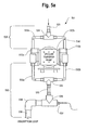
- FIG. 5 a is a top view of a ClO 2 gas stream pump configuration in a ClO 2 solution generator, but without the temperature control capability of the present technique.
- FIG. 5 b is a top view of a first embodiment of a ClO 2 gas stream pump configuration for a ClO 2 solution generator having temperature control capability.
- FIG. 5 c is a top view of a second embodiment of a ClO 2 gas stream pump configuration for a ClO 2 solution generator having temperature control capability.
- FIG. 6 is a top view of an embodiment of a ClO 2 gas stream pump configuration for a ClO 2 solution generator having temperature control capability, similar to the embodiment illustrated in FIG. 5 b, but in which a water stream is mixed with the ClO 2 stream to further control the temperature of the ClO 2 stream before introducing the mixed stream to the absorption loop.
- FIG. 1 illustrates a process flow diagram of an embodiment of chlorine dioxide solution generator 100 of the type described in application Ser. No. 10/902,681.
- the process flow of FIG. 1 consists of three sub-processes including an anolyte loop 102 , a catholyte loop 104 , and an absorption loop 106 .
- the purpose of anolyte loop 102 is to produce a ClO 2 gas by oxidation of chlorite, and the process can be referred to as a ClO 2 gas generator loop.
- the ClO 2 gas generator loop is essentially a ClO 2 gas source.
- Various sources of ClO 2 are available and known in the water treatment field.
- Catholyte loop 104 of the ClO 2 gas generator loop produces sodium hydroxide and hydrogen gas by reduction of water.
- the ClO 2 gas is transferred to absorption loop 106 where the gas is further conditioned for water treatment end-uses.
- the process can be operated through a program logic control (PLC) system 108 that can include visual and/or audible displays.
- PLC program logic control
- the term “absorb” refers to the process of dissolving or infusing a gaseous constituent into a liquid, optionally using pressure to effect the dissolution or infusion.
- ClO 2 gas which is produced in the ClO 2 gas generator loop, is “absorbed” (that is, dissolved or infused) into an aqueous liquid stream directed through absorption loop 106 .
- FIG. 2 illustrates an anolyte loop 102 in an embodiment of chlorine dioxide solution generator 100 of the type described in the '681 application.
- the contribution of anolyte loop 102 to the ClO 2 solution generator is to produce a ClO 2 gas that is directed to absorption loop 106 for further processing.
- Anolyte loop 102 embodiment of FIG. 2 is for a ClO 2 gas produced using a reactant feedstock 202 .
- a 25 percent by weight sodium chlorite (NaClO 2 ) solution can be used as reactant feedstock 202 .
- feedstock concentrations ranging from 0 percent to a maximum solubility (40 percent at 17° C. in the embodiment involving NaClO 2 ), or other suitable method of injecting suitable electrolytes, can be employed.
- the reactant feedstock 202 is connected to a chemical metering pump 204 , which delivers the reactant feedstock 202 to a recirculating connection 206 in the anolyte loop 102 .
- Recirculating connection 206 in anolyte loop connects a stripper column 208 to an electrochemical cell 210 .
- the delivery of the reactant feedstock 202 can be controlled using PLC system 108 .
- PLC system 108 can be used to activate chemical metering pump 204 according to signals received from a pH sensor 212 .
- pH sensor 212 is generally located along recirculating connection 206 .
- a pH set point can be established in PLC system 108 , and once the set point is reached, the delivery of reactant feedstock 202 can either start or stop.
- Reactant feedstock 202 is delivered to a positive end 214 of electrochemical cell 210 where the reactant feedstock is oxidized to form a ClO 2 gas, which is then dissolved in an electrolyte solution along with other side products.
- the ClO 2 solution with the side products is directed away from electrochemical cell 210 to the top of stripper column 208 where a pure ClO 2 is stripped off in a gaseous form from the other side products.
- Side products or byproducts can include chlorine, chlorates, chlorites and/or oxygen.
- the pure ClO 2 gas is then removed from stripper column 208 under a vacuum induced by gas transfer pump 216 , or analogous gas or fluid transfer device (such as, for example, a vacuum-based device), where it is delivered to adsorption loop 106 .
- the remaining solution is collected at the base of stripper column 208 and recirculated back across the pH sensor 212 where additional reactant feedstock 202 can be added.
- the process with the reactant feedstock and/or recirculation solution being delivered into positive end 214 of electrochemical cell 210 is then repeated.
- anolyte hold tank can be used in place of a stripper column.
- an inert gas or air can be blown over the surface or through the solution to separate the ClO 2 gas from the anolyte.
- chlorate can be reduced to produce ClO 2 in a cathode loop instead of chlorite. The ClO 2 gas would then similarly be transferred to the absorption loop.
- ClO 2 can be generated by purely chemical generators and transferred to an absorption loop for further processing.
- FIG. 3 illustrates a catholyte loop 104 in an embodiment of a chlorine dioxide solution generator 100 of the type described in the '681 application.
- Catholyte loop 104 contributes to the chlorine dioxide solution generator 100 by handling byproducts produced from the electrochemical reaction of reactant feedstock 202 solution in anolyte loop 102 .
- sodium chlorite (NaClO 2 ) solution is used as reactant feedstock 202
- sodium ions from the anolyte loop 102 migrate to catholyte loop 104 through a cationic membrane 302 , in electrochemical cell 210 , to maintain charge neutrality.
- Water in the catholyte is reduced to produce hydroxide and hydrogen (H 2 ) gas.
- the resulting byproducts in catholyte loop 104 in the example of an NaClO 2 reactant feedstock, are sodium hydroxide (NaOH) and hydrogen gas.
- the byproducts are directed to a byproduct tank 304 .
- a soft (that is, demineralized) water source 306 can be used to dilute the byproduct NaOH using a solenoid valve 308 connected between soft water source 306 and the byproduct tank 304 .
- Solenoid valve 308 can be controlled with PLC system 108 .
- PLC system 108 can use a timing routine that maintains the NaOH concentration in a range of 5 percent to 20 percent.
- catholyte loop 104 self circulates using the lifting properties of the H 2 byproduct gas formed during the electrochemical process and forced water feed from soft water source 306 .
- the H 2 gas rises up in byproduct tank 304 where there is a hydrogen disengager 310 .
- the H 2 gas can be diluted with air in hydrogen disengager 310 to a concentration of less than 0.5 percent.
- the diluted H 2 gas can be discharged from catholyte loop 104 and chlorine dioxide solution generator 100 using a blower 312 .
- dilute sodium hydroxide can be fed instead of water to produce concentrated sodium hydroxide.
- Oxygen or air can also be used as a reductant instead of water to reduce overall operation voltage since oxygen reduces at lower voltage than water.
- the reaction of anolyte loop 102 and catholyte loop 104 in the embodiment illustrated in FIGS. 2 and 3 is represented by the following net chemical equation: 2NaClO 2(aq) +2H 2 O ⁇ 2ClO 2(gas) +2NaOH (aq) +H 2(gas)
- the NaClO 2 is provided by reactant feedstock 202 of anolyte loop 102 .
- the NaOH and H 2 gas are byproducts of the reaction in catholyte loop 104 .
- the ClO 2 solution along with the starting unreacted NaClO 2 and other side products are directed to the stripper column for separating into ClO 2 gas as part of anolyte loop 102 process. Chlorite salts other than NaClO 2 can be used in anolyte loop 102 .
- FIG. 4 illustrates an absorption loop 106 of an embodiment of a chlorine dioxide solution generator 100 of the type described in the '681 application.
- Absorption loop 106 processes the ClO 2 gas from anolyte loop 102 into a ClO 2 solution that is ready to be directed to the water selected for treatment.
- ClO 2 gas is removed from stripper column 208 of anolyte loop 102 using gas transfer pump 216 .
- a gas transfer pump 216 can be used that is “V” rated at 75 Torr (10 kPa) with a discharge rate of 34 liters per minute.
- the vacuum and delivery rate of gas transfer pump 216 can vary depending upon the free space in stripper column 208 and desired delivery rate of ClO 2 solution.
- the ClO 2 gas removed from stripper column 208 using gas transfer pump 216 is directed to an absorber tank 402 of absorption loop 106 .
- discharge side 404 of gas transfer pump 216 delivers ClO 2 gas into a 0.5-inch (13-mm) poly(vinyl chloride) (PVC) injection line 406 external to absorber tank 402 .
- Injection line 406 is an external bypass for fluid between the lower to the upper portions of the absorption tank 402 .
- a gas injection line can be connected to injection line 406 using a T-connection 408 .
- the tank 402 is filled with water to approximately 0.5 inch (13 mm) below a main level control 410 .
- Main level control 410 can be located below where injection line 406 connects to the upper portion of absorption tank 402 . Introducing ClO 2 gas into injection line 406 can cause a liquid lift that pushes newly absorbed ClO 2 solution up past a forward-only flow switch 412 and into absorber tank 402 . Flow switch 412 controls the amount of liquid delivered to absorber tank 402 .
- Absorber tank 402 has a main control level 410 to maintain a proper tank level.
- safety control levels can be employed to maintain a high level 414 and low level 416 of liquid where main control level 410 fails.
- a process delivery pump 418 feeds ClO 2 solution from absorption tank 402 to the end process without including air or other gases. Process delivery pump 418 is sized to deliver a desired amount of water per minute. The amount of ClO 2 gas delivered to absorber tank 402 is set by the vacuum and delivery rate set by gas transfer pump 216 .
- PLC system 108 can provide a visual interface for the operator to operate the entire chlorine dioxide solution generator 100 .
- PLC system 108 can automatically control the continuous operation and safety of the production of ClO 2 solution.
- PLC system 108 can set flow rates for anolyte loop 102 and catholyte loop 104 .
- the safety levels of absorber tank 402 can also be enforced by PLC system 108 .
- PLC system 108 can also control the power for achieving a desired current in an embodiment using an electrochemical cell 210 .
- the current ranges from 0 to 100 amperes, although currents higher than this average are possible.
- the amount of current determines the amount of ClO 2 gas that is produced in anolyte loop 102 .
- the current of the power supply can be determined by the amount of ClO 2 that is to be produced.
- PLC system 108 can also be used to monitor the voltage of electrochemical cell 210 .
- electrochemical cell 210 can be shut down when the voltage exceeds a safe voltage level. In another preferred embodiment, 5 volts can be considered a safe voltage level.
- PLC system 108 can also monitor the pH of the anolyte using a pH sensor 212 (shown in FIG. 2 ).
- a pH sensor 212 shown in FIG. 2 .
- the pH of the solution circulating in anolyte loop 102 decreases as hydrogen ions are generated.
- additional reactant feedstock is added using PLC system 108 .
- Control of pH can also be handled by adding a reactant that decreases the pH when pH may is too high.
- the transfer line from gas transfer pump 216 can be connected to absorber tank 402 directly without injection line 406 , and can allow for increasing the transfer rate of the pump.
- Other embodiments can include a different method of monitoring the liquid level in absorber tank 402 .
- an oxidation and reduction potential (ORP) can be dipped in absorber tank 402 .
- ORP can be used to monitor the concentration of ClO 2 in the solution in absorber tank 402 .
- PLC system 108 can be used to set a concentration level for the ClO 2 as monitored by ORP, which provides an equivalent method of controlling the liquid level in absorber tank 402 .
- Optical techniques such as photometers can also be used to control the liquid level in absorber tank 402 .
- Absorption loop 106 can be a part of the chlorine dioxide solution generator or it can be installed as a separate unit outside of the chlorine dioxide solution generator.
- process water can be fed directly in absorber tank 402 and treated water can be removed from the absorber tank 402 .
- the process water can include a demineralized, or soft, water source 420 and the process water feed can be controlled using a solenoid valve 422 .
- FIGS. 1, 2 and 3 of the '681 application are based on ClO 2 gas produced using electrochemical cells and a sodium chlorite solution.
- ClO 2 gas can be made using many different processes that would be familiar to a person skilled in water treatment technologies.
- Such processes include, but are not limited to, acidification of chlorite, oxidation of chlorite by chlorine, oxidation of chlorite by persulfate, use of acetic anhydride on chlorite, use of sodium hypochlorite and sodium chlorite, use of dry chlorine/chlorite, reduction of chlorates by acidification in the presence of oxalic acid, reduction of chlorates by sulfur dioxide, and the ERCO R-2®, R-3®, R-5®, R-8®, R-10® and R-11® processes.
- the material, the diameter, as well as the relative configuration and arrangement of the conduits (or pipes or tubes) associated with the present chlorine dioxide solution generator are important for safe, efficient and reliable operation of the generator.
- the ClO 2 gas stream should be removed the generator at temperature greater than about 163° F. (73° C.) , depending upon the diameter of the conduit or tube through which the ClO 2 gas stream is carried.
- ClO 2 at a temperature greater than about 163° F. (73° C.) can decompose to form chlorine and oxygen. Such decomposition is typically accompanied by an increase in the temperature of the ClO 2 stream, with temperatures as high 280° F. (138° C.), which is greater than the melting temperature of both PVC and CPVC (chlorinated poly(vinyl chloride)).
- PVC and CPVC are the typical materials from which the fluid stream conduits or pipes employed in chlorine dioxide solution generators, and the melting of those conduits can create hazardous operating conditions. It is therefore important to reduce and maintain the temperature of the chloride dioxide stream exiting the generator as low as possible.
- FIG. 5 a shows a ClO 2 gas stream pump configuration 501 in a ClO 2 solution generator, but without the temperature control capability of the present technique.
- Pump configuration 501 is interposed between a ClO 2 gas source of the type illustrated in FIGS. 1 and 2 , and an absorption loop of the type illustrated in FIGS. 1 and 4 .
- Pump configuration 501 includes a gas transfer pump 510 interposed between an inlet manifold assembly 505 and an exhaust manifold assembly 506 .
- Gas transfer pump 510 has two head portions 512 a and 512 b, which produce a pressurized gas stream from an incoming gas stream.
- a ClO 2 gas stream from a ClO 2 gas source (not shown) is directed to pump 510 via conduit 520 , which branches at T-connector 524 to a pair of inlet conduits 522 a, 522 b.
- the ClO 2 gas stream in inlet conduit 512 a is fed to pump head 512 a, where the stream is pressurized and discharged from pump head 512 a via outlet conduit 532 a.
- the ClO 2 gas stream in inlet conduit 512 b is fed to pump head 512 b, where the stream is pressurized and discharged from pump head 512 b via outlet conduit 532 b.
- the pressurized ClO 2 gas streams directed through outlet conduits 532 a, 532 b are combined into one stream at T-connector 534 , and the combined stream is then directed through conduit 533 to a fitting 536 , in which a thermocouple 537 is mounted and from which the combined stream is directed to the absorption loop (not shown) via conduit 539 and intermediate pipe connections and fittings, one of which is illustrated in FIG. 5 a as elbow fitting 538 .
- FIG. 5 b shows an embodiment of a ClO 2 gas stream pump configuration 502 for a ClO 2 solution generator having temperature control capability.
- pump configuration 502 is interposed between a ClO 2 gas source of the type illustrated in FIGS. 1 and 2 , and an absorption loop of the type illustrated in FIGS. 1 and 4 .
- Pump configuration 502 includes gas transfer pump 510 , an inlet manifold assembly 505 , which as illustrated in FIG. 5 b is essentially identical to the inlet manifold assembly shown in FIG. 5 a.
- Pump configuration 502 also includes an exhaust manifold assembly 507 , in which the inlet streams are pressurized and discharged from pump heads 512 a, 512 b via outlet conduits 532 a, 532 b, respectively.
- the pressurized ClO 2 gas streams directed through outlet conduits 532 a, 532 b are separately directed to conduits in which the pressurized streams undergo volumetric expansion.
- the pressurized ClO 2 gas stream in outlet conduit 532 a is directed to and expanded within a T-connector 546
- the pressurized ClO 2 gas stream in outlet conduit 532 b is directed to an elbow fitting 542 , in which a thermocouple 537 is mounted and from which the stream is directed through conduit 544 .
- the stream directed through conduit 544 is combined with the other pressurized and expanded ClO 2 gas stream at T-connector 546 , and the combined stream is then directed from T-connector 546 to the downstream absorption loop via conduit 548 (and intermediate pipe connections and fittings, if any (not shown in FIG. 5 b )).
- FIG. 5 c shows an embodiment of a ClO 2 gas stream pump configuration 503 for a ClO 2 solution generator having temperature control capability.
- pump configuration 503 is interposed between a ClO 2 gas source of the type illustrated in FIGS. 1 and 2 , and an absorption loop of the type illustrated in FIGS. 1 and 4 .
- Pump configuration 503 includes gas transfer pump 510 , an inlet manifold assembly 505 , which as illustrated in FIG. 5 c is essentially identical to the inlet manifold assembly shown in FIGS. 5 a and 5 b.
- Pump configuration 503 also includes an exhaust manifold assembly 508 , in which the inlet streams are pressurized and discharged from pump head 512 a via outlet conduits 552 a, 552 b and from pump head 512 b via outlet conduits 552 c, 552 d.
- the pressurized ClO 2 gas streams directed through outlet conduits 552 a, 552 b, 552 c, 552 d are separately directed to a single conduit 554 , in which the pressurized streams are combined and undergo volumetric expansion.
- the stream directed through conduit 554 is then directed to the downstream absorption loop (not shown) via conduit 558 (and intermediate pipe connections and fittings, if any).
- Thermocouples 557 a, 557 b are mounted on opposite ends of
- FIG. 6 shows a ClO 2 gas stream pump configuration 504 for a chlorine dioxide solution generator having temperature control capability, which is similar to the embodiment illustrated in FIG. 5 b, but in which a water stream directed through conduit 559 is mixed with a pressurized ClO 2 gas stream to control the temperature of the ClO 2 stream(s) before introducing the mixed stream(s) to the absorption loop.
- the ClO 2 gas stream exiting the pump orifice in FIGS. 5 a, 5 b and 5 c, which has a diameter of 0.25 inch (0.64 cm) can be cooled by expanding the volume of the gas stream.
- the extent of expansion should be such that the induction period for decomposition of ClO 2 at the temperature and pressure indicated is greater than 20 seconds.
- the temperature and induction period for 5 percent by volume of ClO 2 in air corresponds to a partial pressure of 38 mm of Hg shown in Table 1 below.
- the ClO 2 temperature is preferably reduced to and maintained at below 163° F. (73° C.). This can be accomplished in several ways, as illustrated with reference to the embodiments of FIGS. 5 a, 5 b and 5 c.
- the temperatures of the pressurized ClO 2 gas streams were measured at thermocouple 537 (in the embodiment of FIG. 5 a ), at thermocouple 543 (in the embodiment of FIG. 5 b ), and at thermocouple 557 b (in the embodiment of FIG. 5 c ).
- the operating data is shown in Table 2 below. TABLE 2 Temperature of ClO 2 for various nominal diameters of the conduits depicted in FIGS.
- Another way of reducing the temperature of the ClO 2 stream is to introduce water at the conduit, such as, for example, the conduit formed in T-connector 541 shown in FIG. 6 , in which a water stream is mixed with the ClO 2 stream to control the temperature of the ClO 2 stream before introducing the mixed stream to the vacuum gas transfer pump.
Landscapes
- Chemical & Material Sciences (AREA)
- Organic Chemistry (AREA)
- Life Sciences & Earth Sciences (AREA)
- General Life Sciences & Earth Sciences (AREA)
- Geology (AREA)
- Engineering & Computer Science (AREA)
- Inorganic Chemistry (AREA)
- Chemical Kinetics & Catalysis (AREA)
- Electrochemistry (AREA)
- Hydrology & Water Resources (AREA)
- Environmental & Geological Engineering (AREA)
- Water Supply & Treatment (AREA)
- General Chemical & Material Sciences (AREA)
- Metallurgy (AREA)
- Materials Engineering (AREA)
- Treating Waste Gases (AREA)
- Electrolytic Production Of Non-Metals, Compounds, Apparatuses Therefor (AREA)
Abstract
Description
- This application is a continuation-in-part of U.S. patent application Ser. No. 10/902,681 filed on Jul. 29, 2004, entitled “Chlorine Dioxide Solution Generator”. The '681 application is hereby incorporated by reference herein in its entirety.
- The present invention relates generally to chlorine dioxide generators and to the use of such generators in water treatment systems. More particularly, the present invention relates to a chlorine dioxide generator for producing a chlorine dioxide solution, in which the temperature of the chlorine dioxide stream is controlled to reduce or avoid decomposition of chlorine dioxide in the stream.
- Chlorine dioxide (ClO2) has many industrial and municipal uses. When produced and handled properly, ClO2 is an effective and powerful biocide, disinfectant and oxidizer.
- ClO2 is also used extensively in the pulp and paper industry as a bleaching agent, but is gaining further support in such areas as disinfections in municipal water treatment. Other end-uses can include as a disinfectant in the food and beverage industries, wastewater treatment, industrial water treatment, cleaning and disinfections of medical wastes, textile bleaching, odor control for the rendering industry, circuit board cleansing in the electronics industry, and uses in the oil and gas industry.
- In water treatment applications, ClO2 is primarily used as a disinfectant for surface waters with odor and taste problems. It is an effective biocide at low concentrations and over a wide pH range. ClO2 is desirable because when it reacts with an organism in water, chlorite results, which studies to date have shown does not pose a significant adverse risk to human health. The use of chlorine, on the other hand, can result in the creation of chlorinated organic compounds when treating water. Such chlorinated organic compounds are suspected to increase cancer risk.
- Producing ClO2 gas for use in a ClO2 water treatment process is desirable because there is greater assurance of ClO2 purity when in the gas phase. ClO2 is, however, unstable in the gas phase and will readily undergo decomposition into chlorine gas (C12), oxygen gas (O2), and heat. The high reactivity of ClO2 generally requires that it be produced and used at the same location. ClO2 is, however, soluble and stable in an aqueous solution.
- The production of ClO2 can be accomplished both by electrochemical and reactor-based chemical methods. Electrochemical methods have an advantage of relatively safer operation compared to reactor-based chemical methods. In this regard, electrochemical methods employ only one precursor, namely, a chlorite solution, unlike the multiple precursors that are employed in reactor-based chemical methods. Moreover, in reactor-based chemical methods, the use of concentrated acids and chlorine gas poses a safety concern.
- Electrochemical cells are capable of carrying out selective oxidation reaction of chlorite to ClO2 The selective oxidation reaction product is a solution containing ClO2. To further purify the ClO2 gas stream, the gas stream is separated from the solution using a stripper column. In the stripper column, air is passed from the bottom of the column to the top while the ClO2 solution travels from top to the bottom. Pure ClO2 is exchanged from solution to the air. Suction of air is usually accomplished using an eductor, as described in copending and co-owned application Ser. No. 10/902,681, of which the present application is a continuation-in-part.
- As described in the '681 application, ClO2 can be prepared a number of ways, generally via a reaction involving either chlorite (ClO2—) or chlorate (ClO3—) solutions. The ClO2 created through such a reaction is often refined to generate ClO2 gas for use in the water treatment process. The ClO2 gas is then educed into the water selected for treatment. Eduction occurs where the ClO2 gas, in combination with air, is mixed with the water selected for treatment.
- As further described in the '681 application, for many water treatment systems, the eduction process is effective to introduce ClO2 gas directly into the process water. An operational problem can occur, however, when air is simultaneously introduced into a water system while educing the ClO2 gas. A significant corrosion potential results from oxygen in air being added into the system.
- Another problem can occur when introducing ClO2 gas into a pressurized water system. Treating water in pressurized systems can be difficult when using educed ClO2 gas, since high-pressure booster pumps may be needed along with high-performance eductors. This not only increases cost, but also raises maintenance concerns, since high-performance eduction systems can be unreliable as operating pressures near or above 30 to 50 pounds per square inch (psi) (206.8 to 344.7 kilopascal (kPa)).
- The foregoing eductor-based method is less effective, however, in systems in which a ClO2 stream is directed against a head pressure. To overcome this deficiency, a vacuum gas transfer pump can be employed instead of the eductor described in the '681 application. The size and capacity of the vacuum gas transfer pump are preferably determined by parameters associated with safe, efficient and reliable operation of the generator. In this regard, it has been determined that, for safe, efficient and reliable operation of the generator, a ClO2 concentration of less than about 10 percent by volume of a stream comprising ClO2 in air, the lower decomposition limit, is preferred. To further increase the safety margin of the generator, a ClO2 concentration of less than about 5 percent by volume of a stream comprising ClO2 in air is more desirable.
- As the amount of ClO2 produced by the generator increases, the amount of air required for the effective operation of the stripper column also increases. The production range of the generator therefore determines the size of the vacuum gas transfer pump. As the pump size increase the velocity of the mixed air/ClO2 stream exiting the pump increases. Consequently, the temperature of the gas mixture increases.
- It is known that ClO2 is unstable and capable of decomposing, in which ClO2 undergoes an exothermic reaction to form chlorine and oxygen. In fact, and as described in more detail below, an operating temperature greater than about 163° F. (73° C.) can result in potentially hazardous and less efficient operation of the generator. In the present technique, in which the ClO2 solution generator has temperature control capability, the operating temperature can be reduced and maintained below the level at which the exothermic reaction to form chlorine and oxygen causes the ClO2 generation process to become hazardous and less efficient.
- A chlorine dioxide solution generator comprises a ClO2 gas source, an absorption loop for effecting the dissolution of ClO2 into a liquid stream, the absorption loop fluidly connected to the ClO2 gas source, and a gas transfer assembly interposed between the ClO2 gas source and the absorption loop. The gas transfer assembly comprises:
-
- (1) a gas transfer pump having at least one inlet port for receiving a ClO2 gas stream from the ClO2 gas source and at least one outlet port for discharging a pressurized ClO2 gas stream; and
- (2) an exhaust manifold assembly extending from the at least one gas transfer pump outlet port.
The exhaust manifold assembly comprises at least one manifold conduit defining an interior volume for directing the pressurized ClO2 gas stream from the at least one gas transfer pump outlet port to the absorption loop. The at least one manifold conduit interior volume is sufficiently large to inhibit ClO2 decomposition in the pressurized ClO2 gas stream.
- In a preferred chlorine dioxide solution generator, the at least one manifold conduit interior volume is sufficiently large to induce a pressurized ClO2 gas stream temperature within the at least one manifold conduit of less than about 163° F. (73° C.).
- In a preferred chlorine dioxide solution generator, the gas transfer pump has first and second inlet ports for receiving first and second ClO2 gas streams from the ClO2 gas source. The gas transfer pump has first and second outlet ports for discharging first and second pressurized ClO2 gas streams. The discharge manifold assembly comprises first and second manifold conduits defining an aggregate conduit interior volume for directing the first and second pressurized ClO2 gas streams, respectively, from the gas transfer pump to the absorption loop. The aggregate manifold conduit interior volume is sufficiently large to inhibit ClO2 decomposition in the pressurized ClO2 gas stream.
- In a preferred chlorine dioxide solution generator, the first and second inlet ports each has an inlet port conduit extending therefrom for receiving first and second ClO2 gas streams from the ClO2 gas source. The first and second outlet ports each has an outlet port conduit extending therefrom for discharging first and second pressurized ClO2 gas streams. The exhaust manifold assembly comprises first and second manifold conduits defining an aggregate conduit interior volume for directing the first and second pressurized ClO2 gas streams, respectively, from the gas transfer pump to the absorption loop. The aggregate manifold conduit interior volume is sufficiently large to inhibit ClO2 decomposition in the pressurized ClO2 gas stream.
- In a preferred chlorine dioxide solution generator, the first and second inlet ports each has an inlet port conduit extending therefrom for receiving first and second ClO2 gas streams from the ClO2 gas source. The first and second outlet ports each has a pair of outlet port conduits extending therefrom for discharging two pairs of pressurized ClO2 gas streams. The exhaust manifold assembly comprises at least one manifold conduit defining an aggregate conduit interior volume for directing the first and second pressurized ClO2 gas streams, respectively, from the gas transfer pump to the absorption loop. The aggregate manifold conduit interior volume is sufficiently large to inhibit ClO2 decomposition in the pressurized ClO2 gas stream. The exhaust manifold assembly preferably comprises a single manifold conduit defining an interior volume for directing the two pairs of pressurized ClO2 gas streams from the gas transfer pump to the absorption loop. The interior volume is sufficiently large to inhibit ClO2 decomposition in the pressurized ClO2 gas stream.
- In preferred embodiments of the chlorine dioxide solution generator, the outlet port conduits are preferably formed from a material selected from the group consisting of polytetrafluoroethylene (PTFE; commercially available from DuPont under the trade name Teflon®, polychlorotrifluoroethylene, chlorinated poly(vinyl chloride), titanium and other metals having a melting point greater than about 140° F. (60° C.).
- In preferred embodiments of the chlorine dioxide solution generator, a ratio of the cross-sectional diameter of the at least one manifold conduit to the cross-sectional diameter of the at least one gas transfer pump outlet port is greater than 1.
- In preferred embodiments of the chlorine dioxide solution generator, the exhaust manifold assembly has a coolant fluid stream in thermal contact therewith. In operation, the coolant fluid stream further inhibits ClO2 decomposition in the pressurized ClO2 gas stream. The coolant fluid stream is preferably in thermal contact with the at least one manifold conduit. The thermal contact of the coolant fluid stream with the at least one manifold conduit further induces a pressurized ClO2 gas stream temperature within the at least one manifold conduit of less than about 163° F. (73° C.).
- A method of generating a chlorine dioxide solution comprises:
-
- (a) providing a source of ClO2 gas;
- (b) effecting the dissolution of ClO2 into a liquid stream by employing an absorption loop fluidly connected to the ClO2 gas source;
- (c) interposing a gas transfer pump between the ClO2 gas source and the absorption loop, the gas transfer pump having at least one inlet port for receiving a ClO2 gas stream from the ClO2 gas source and at least one outlet port for discharging a pressurized ClO2 gas stream;
- (d) interposing an exhaust manifold assembly between the gas transfer pump outlet port and the absorption loop, the exhaust manifold assembly comprising at least one manifold conduit defining an interior volume for directing the pressurized ClO2 gas stream from the at least one gas transfer pump outlet port to the absorption loop; and
- (e) inhibiting ClO2 decomposition in the pressurized ClO2 gas stream by effecting a volumetric increase between the at least one gas transfer pump outlet port and the at least one manifold conduit.
- In a preferred embodiments of the method, the volumetric increase induces a pressurized ClO2 gas stream temperature within the at least one manifold conduit of less than about 163° F. (73° C.).
-
FIG. 1 is a process flow diagram of a ClO2 solution generator of the type described in application Ser. No. 10/902,681. -
FIG. 2 is a process flow diagram of an anolyte loop of a ClO2 solution generator of the type described in the '681 application. -
FIG. 3 is a process flow diagram of a catholyte loop of a ClO2 solution generator of the type described in the '681 application. -
FIG. 4 is a process flow diagram of an absorption loop of a ClO2 solution generator of the type described in the '681 application. -
FIG. 5 a is a top view of a ClO2 gas stream pump configuration in a ClO2 solution generator, but without the temperature control capability of the present technique. -
FIG. 5 b is a top view of a first embodiment of a ClO2 gas stream pump configuration for a ClO2 solution generator having temperature control capability. -
FIG. 5 c is a top view of a second embodiment of a ClO2 gas stream pump configuration for a ClO2 solution generator having temperature control capability. -
FIG. 6 is a top view of an embodiment of a ClO2 gas stream pump configuration for a ClO2 solution generator having temperature control capability, similar to the embodiment illustrated inFIG. 5 b, but in which a water stream is mixed with the ClO2 stream to further control the temperature of the ClO2 stream before introducing the mixed stream to the absorption loop. -
FIG. 1 illustrates a process flow diagram of an embodiment of chlorinedioxide solution generator 100 of the type described in application Ser. No. 10/902,681. The process flow ofFIG. 1 consists of three sub-processes including ananolyte loop 102, acatholyte loop 104, and anabsorption loop 106. The purpose ofanolyte loop 102 is to produce a ClO2 gas by oxidation of chlorite, and the process can be referred to as a ClO2 gas generator loop. The ClO2 gas generator loop is essentially a ClO2 gas source. Various sources of ClO2 are available and known in the water treatment field.Catholyte loop 104 of the ClO2 gas generator loop produces sodium hydroxide and hydrogen gas by reduction of water. Once the ClO2 gas is produced in the ClO2 gas generator loop, the ClO2 gas is transferred toabsorption loop 106 where the gas is further conditioned for water treatment end-uses. The process can be operated through a program logic control (PLC)system 108 that can include visual and/or audible displays. - In this application, the term “absorb” refers to the process of dissolving or infusing a gaseous constituent into a liquid, optionally using pressure to effect the dissolution or infusion. Here, ClO2 gas, which is produced in the ClO2 gas generator loop, is “absorbed” (that is, dissolved or infused) into an aqueous liquid stream directed through
absorption loop 106. -
FIG. 2 illustrates ananolyte loop 102 in an embodiment of chlorinedioxide solution generator 100 of the type described in the '681 application. The contribution ofanolyte loop 102 to the ClO2 solution generator is to produce a ClO2 gas that is directed toabsorption loop 106 for further processing.Anolyte loop 102 embodiment ofFIG. 2 is for a ClO2 gas produced using areactant feedstock 202. In a preferred embodiment, a 25 percent by weight sodium chlorite (NaClO2) solution can be used asreactant feedstock 202. However, feedstock concentrations ranging from 0 percent to a maximum solubility (40 percent at 17° C. in the embodiment involving NaClO2), or other suitable method of injecting suitable electrolytes, can be employed. - The
reactant feedstock 202 is connected to achemical metering pump 204, which delivers thereactant feedstock 202 to arecirculating connection 206 in theanolyte loop 102.Recirculating connection 206 in anolyte loop connects astripper column 208 to anelectrochemical cell 210. The delivery of thereactant feedstock 202 can be controlled usingPLC system 108.PLC system 108 can be used to activatechemical metering pump 204 according to signals received from apH sensor 212.pH sensor 212 is generally located along recirculatingconnection 206. A pH set point can be established inPLC system 108, and once the set point is reached, the delivery ofreactant feedstock 202 can either start or stop. -
Reactant feedstock 202 is delivered to apositive end 214 ofelectrochemical cell 210 where the reactant feedstock is oxidized to form a ClO2 gas, which is then dissolved in an electrolyte solution along with other side products. The ClO2 solution with the side products is directed away fromelectrochemical cell 210 to the top ofstripper column 208 where a pure ClO2 is stripped off in a gaseous form from the other side products. Side products or byproducts can include chlorine, chlorates, chlorites and/or oxygen. The pure ClO2 gas is then removed fromstripper column 208 under a vacuum induced bygas transfer pump 216, or analogous gas or fluid transfer device (such as, for example, a vacuum-based device), where it is delivered toadsorption loop 106. The remaining solution is collected at the base ofstripper column 208 and recirculated back across thepH sensor 212 whereadditional reactant feedstock 202 can be added. The process with the reactant feedstock and/or recirculation solution being delivered intopositive end 214 ofelectrochemical cell 210 is then repeated. - As described in the '681 application, modifications to the anolyte loop process can be made that achieve similar results. As an example, an anolyte hold tank can be used in place of a stripper column. In such a case, an inert gas or air can be blown over the surface or through the solution to separate the ClO2 gas from the anolyte. As another example, chlorate can be reduced to produce ClO2 in a cathode loop instead of chlorite. The ClO2 gas would then similarly be transferred to the absorption loop. In a further example, ClO2 can be generated by purely chemical generators and transferred to an absorption loop for further processing.
-
FIG. 3 illustrates acatholyte loop 104 in an embodiment of a chlorinedioxide solution generator 100 of the type described in the '681 application.Catholyte loop 104 contributes to the chlorinedioxide solution generator 100 by handling byproducts produced from the electrochemical reaction ofreactant feedstock 202 solution inanolyte loop 102. As an example, where a sodium chlorite (NaClO2) solution is used asreactant feedstock 202, sodium ions from theanolyte loop 102 migrate to catholyteloop 104 through acationic membrane 302, inelectrochemical cell 210, to maintain charge neutrality. Water in the catholyte is reduced to produce hydroxide and hydrogen (H2) gas. The resulting byproducts incatholyte loop 104, in the example of an NaClO2 reactant feedstock, are sodium hydroxide (NaOH) and hydrogen gas. The byproducts are directed to abyproduct tank 304. - In an embodiment of
catholyte loop 104 in the example of a NaClO2 reactant feedstock, a soft (that is, demineralized)water source 306 can be used to dilute the byproduct NaOH using asolenoid valve 308 connected betweensoft water source 306 and thebyproduct tank 304.Solenoid valve 308 can be controlled withPLC system 108. In a preferred embodiment,PLC system 108 can use a timing routine that maintains the NaOH concentration in a range of 5 percent to 20 percent. Whenbyproduct tank 304 reaches a predetermined level above the base ofbyproduct tank 304, the diluted NaOH byproduct above that level is removed fromcatholyte loop 104. - In the example of a NaClO2 reactant feedstock,
catholyte loop 104 self circulates using the lifting properties of the H2 byproduct gas formed during the electrochemical process and forced water feed fromsoft water source 306. The H2 gas rises up inbyproduct tank 304 where there is ahydrogen disengager 310. The H2 gas can be diluted with air inhydrogen disengager 310 to a concentration of less than 0.5 percent. The diluted H2 gas can be discharged fromcatholyte loop 104 and chlorinedioxide solution generator 100 using ablower 312. - As described in the '681 application, in another embodiment, dilute sodium hydroxide can be fed instead of water to produce concentrated sodium hydroxide. Oxygen or air can also be used as a reductant instead of water to reduce overall operation voltage since oxygen reduces at lower voltage than water.
- The reaction of
anolyte loop 102 andcatholyte loop 104 in the embodiment illustrated inFIGS. 2 and 3 is represented by the following net chemical equation:
2NaClO2(aq)+2H2O→2ClO2(gas)+2NaOH(aq)+H2(gas)
The NaClO2 is provided byreactant feedstock 202 ofanolyte loop 102. The NaOH and H2 gas are byproducts of the reaction incatholyte loop 104. The ClO2 solution along with the starting unreacted NaClO2 and other side products are directed to the stripper column for separating into ClO2 gas as part ofanolyte loop 102 process. Chlorite salts other than NaClO2 can be used inanolyte loop 102. -
FIG. 4 illustrates anabsorption loop 106 of an embodiment of a chlorinedioxide solution generator 100 of the type described in the '681 application.Absorption loop 106 processes the ClO2 gas fromanolyte loop 102 into a ClO2 solution that is ready to be directed to the water selected for treatment. - ClO2 gas is removed from
stripper column 208 ofanolyte loop 102 usinggas transfer pump 216. In a preferred embodiment, agas transfer pump 216 can be used that is “V” rated at 75 Torr (10 kPa) with a discharge rate of 34 liters per minute. The vacuum and delivery rate ofgas transfer pump 216 can vary depending upon the free space instripper column 208 and desired delivery rate of ClO2 solution. - The ClO2 gas removed from
stripper column 208 usinggas transfer pump 216 is directed to anabsorber tank 402 ofabsorption loop 106. In a preferred embodiment,discharge side 404 ofgas transfer pump 216 delivers ClO2 gas into a 0.5-inch (13-mm) poly(vinyl chloride) (PVC)injection line 406 external toabsorber tank 402.Injection line 406 is an external bypass for fluid between the lower to the upper portions of theabsorption tank 402. A gas injection line can be connected toinjection line 406 using a T-connection 408. Before ClO2 gas is directed toabsorber tank 402, thetank 402 is filled with water to approximately 0.5 inch (13 mm) below amain level control 410.Main level control 410 can be located below whereinjection line 406 connects to the upper portion ofabsorption tank 402. Introducing ClO2 gas intoinjection line 406 can cause a liquid lift that pushes newly absorbed ClO2 solution up past a forward-only flow switch 412 and intoabsorber tank 402.Flow switch 412 controls the amount of liquid delivered toabsorber tank 402.Absorber tank 402 has amain control level 410 to maintain a proper tank level. In addition tomain control level 410, safety control levels can be employed to maintain ahigh level 414 andlow level 416 of liquid wheremain control level 410 fails. Aprocess delivery pump 418 feeds ClO2 solution fromabsorption tank 402 to the end process without including air or other gases.Process delivery pump 418 is sized to deliver a desired amount of water per minute. The amount of ClO2 gas delivered toabsorber tank 402 is set by the vacuum and delivery rate set bygas transfer pump 216. -
PLC system 108 can provide a visual interface for the operator to operate the entire chlorinedioxide solution generator 100.PLC system 108 can automatically control the continuous operation and safety of the production of ClO2 solution.PLC system 108 can set flow rates foranolyte loop 102 andcatholyte loop 104. The safety levels ofabsorber tank 402 can also be enforced byPLC system 108.PLC system 108 can also control the power for achieving a desired current in an embodiment using anelectrochemical cell 210. In a preferred embodiment, the current ranges from 0 to 100 amperes, although currents higher than this average are possible. The amount of current determines the amount of ClO2 gas that is produced inanolyte loop 102. The current of the power supply can be determined by the amount of ClO2 that is to be produced.PLC system 108 can also be used to monitor the voltage ofelectrochemical cell 210. In a preferred embodiment,electrochemical cell 210 can be shut down when the voltage exceeds a safe voltage level. In another preferred embodiment, 5 volts can be considered a safe voltage level. - As described in the '681 application, another operation that can be monitored with
PLC system 108 is the temperature ofelectrochemical cell 210. If overheating occurs,PLC system 108 shuts downelectrochemical cell 210.PLC system 108 can also monitor the pH of the anolyte using a pH sensor 212 (shown in FIG. 2). During operation ofelectrochemical cell 210, the pH of the solution circulating inanolyte loop 102 decreases as hydrogen ions are generated. In the exemplary embodiment of the NaClO2 reactant feedstock, when the pH goes below 5, additional reactant feedstock is added usingPLC system 108. Control of pH can also be handled by adding a reactant that decreases the pH when pH may is too high. - As further described in the '681 application, in another embodiment, the transfer line from
gas transfer pump 216 can be connected toabsorber tank 402 directly withoutinjection line 406, and can allow for increasing the transfer rate of the pump. Other embodiments can include a different method of monitoring the liquid level inabsorber tank 402. For example, an oxidation and reduction potential (ORP) can be dipped inabsorber tank 402. ORP can be used to monitor the concentration of ClO2 in the solution inabsorber tank 402.PLC system 108 can be used to set a concentration level for the ClO2 as monitored by ORP, which provides an equivalent method of controlling the liquid level inabsorber tank 402. Optical techniques such as photometers can also be used to control the liquid level inabsorber tank 402.Absorption loop 106 can be a part of the chlorine dioxide solution generator or it can be installed as a separate unit outside of the chlorine dioxide solution generator. In another embodiment, process water can be fed directly inabsorber tank 402 and treated water can be removed from theabsorber tank 402. The process water can include a demineralized, or soft,water source 420 and the process water feed can be controlled using asolenoid valve 422. - The process flow illustrated in
FIGS. 1, 2 and 3 of the '681 application are based on ClO2 gas produced using electrochemical cells and a sodium chlorite solution. ClO2 gas can be made using many different processes that would be familiar to a person skilled in water treatment technologies. Such processes include, but are not limited to, acidification of chlorite, oxidation of chlorite by chlorine, oxidation of chlorite by persulfate, use of acetic anhydride on chlorite, use of sodium hypochlorite and sodium chlorite, use of dry chlorine/chlorite, reduction of chlorates by acidification in the presence of oxalic acid, reduction of chlorates by sulfur dioxide, and the ERCO R-2®, R-3®, R-5®, R-8®, R-10® and R-11® processes. - It has been determined that the material, the diameter, as well as the relative configuration and arrangement of the conduits (or pipes or tubes) associated with the present chlorine dioxide solution generator are important for safe, efficient and reliable operation of the generator. In particular, the ClO2 gas stream should be removed the generator at temperature greater than about 163° F. (73° C.) , depending upon the diameter of the conduit or tube through which the ClO2 gas stream is carried.
- As previously stated, it is known that ClO2 at a temperature greater than about 163° F. (73° C.) can decompose to form chlorine and oxygen. Such decomposition is typically accompanied by an increase in the temperature of the ClO2 stream, with temperatures as high 280° F. (138° C.), which is greater than the melting temperature of both PVC and CPVC (chlorinated poly(vinyl chloride)). PVC and CPVC are the typical materials from which the fluid stream conduits or pipes employed in chlorine dioxide solution generators, and the melting of those conduits can create hazardous operating conditions. It is therefore important to reduce and maintain the temperature of the chloride dioxide stream exiting the generator as low as possible.
-
FIG. 5 a shows a ClO2 gasstream pump configuration 501 in a ClO2 solution generator, but without the temperature control capability of the present technique.Pump configuration 501 is interposed between a ClO2 gas source of the type illustrated inFIGS. 1 and 2 , and an absorption loop of the type illustrated inFIGS. 1 and 4 . -
Pump configuration 501 includes agas transfer pump 510 interposed between aninlet manifold assembly 505 and anexhaust manifold assembly 506.Gas transfer pump 510 has twohead portions conduit 520, which branches at T-connector 524 to a pair ofinlet conduits inlet conduit 512 a is fed to pumphead 512 a, where the stream is pressurized and discharged frompump head 512 a viaoutlet conduit 532 a. Similarly, the ClO2 gas stream ininlet conduit 512 b is fed to pumphead 512 b, where the stream is pressurized and discharged frompump head 512 b viaoutlet conduit 532 b. The pressurized ClO2 gas streams directed throughoutlet conduits connector 534, and the combined stream is then directed throughconduit 533 to a fitting 536, in which athermocouple 537 is mounted and from which the combined stream is directed to the absorption loop (not shown) viaconduit 539 and intermediate pipe connections and fittings, one of which is illustrated inFIG. 5 a aselbow fitting 538. -
FIG. 5 b shows an embodiment of a ClO2 gasstream pump configuration 502 for a ClO2 solution generator having temperature control capability. As withpump configuration 501 inFIG. 5 a,pump configuration 502 is interposed between a ClO2 gas source of the type illustrated inFIGS. 1 and 2 , and an absorption loop of the type illustrated inFIGS. 1 and 4 . -
Pump configuration 502 includesgas transfer pump 510, aninlet manifold assembly 505, which as illustrated inFIG. 5 b is essentially identical to the inlet manifold assembly shown inFIG. 5 a.Pump configuration 502 also includes anexhaust manifold assembly 507, in which the inlet streams are pressurized and discharged from pump heads 512 a, 512 b viaoutlet conduits outlet conduits outlet conduit 532 a is directed to and expanded within a T-connector 546, and the pressurized ClO2 gas stream inoutlet conduit 532 b is directed to anelbow fitting 542, in which athermocouple 537 is mounted and from which the stream is directed throughconduit 544. The stream directed throughconduit 544 is combined with the other pressurized and expanded ClO2 gas stream at T-connector 546, and the combined stream is then directed from T-connector 546 to the downstream absorption loop via conduit 548 (and intermediate pipe connections and fittings, if any (not shown inFIG. 5 b)). -
FIG. 5 c shows an embodiment of a ClO2 gasstream pump configuration 503 for a ClO2 solution generator having temperature control capability. As withpump configuration 501 inFIG. 5 a andpump configuration 502 inFIG. 5 b,pump configuration 503 is interposed between a ClO2 gas source of the type illustrated inFIGS. 1 and 2 , and an absorption loop of the type illustrated inFIGS. 1 and 4 . -
Pump configuration 503 includesgas transfer pump 510, aninlet manifold assembly 505, which as illustrated inFIG. 5 c is essentially identical to the inlet manifold assembly shown inFIGS. 5 a and 5 b.Pump configuration 503 also includes anexhaust manifold assembly 508, in which the inlet streams are pressurized and discharged frompump head 512 a viaoutlet conduits pump head 512 b viaoutlet conduits outlet conduits single conduit 554, in which the pressurized streams are combined and undergo volumetric expansion. The stream directed throughconduit 554 is then directed to the downstream absorption loop (not shown) via conduit 558 (and intermediate pipe connections and fittings, if any).Thermocouples conduit 544. -
FIG. 6 shows a ClO2 gasstream pump configuration 504 for a chlorine dioxide solution generator having temperature control capability, which is similar to the embodiment illustrated inFIG. 5 b, but in which a water stream directed throughconduit 559 is mixed with a pressurized ClO2 gas stream to control the temperature of the ClO2 stream(s) before introducing the mixed stream(s) to the absorption loop. - The ClO2 gas stream exiting the pump orifice in
FIGS. 5 a, 5 b and 5 c, which has a diameter of 0.25 inch (0.64 cm) can be cooled by expanding the volume of the gas stream. The extent of expansion should be such that the induction period for decomposition of ClO2 at the temperature and pressure indicated is greater than 20 seconds. According to published graphs in the technical literature (see, for example, Loss Prevention Bulletin, I. Chem. E. 113, October 1993 by G. Cowley), the temperature and induction period for 5 percent by volume of ClO2 in air (corresponds to a partial pressure of 38 mm of Hg) shown in Table 1 below.TABLE 1 Induction period to decomposition of ClO2 (5% by volume in air) at a partial pressure of 38 mm Hg Temperature Induction Period (° F./° C.) (minutes) 163/73 0.33 124/51 60 106/41 400 - In the present chlorine dioxide solution generator with temperature control capability, the ClO2 temperature is preferably reduced to and maintained at below 163° F. (73° C.). This can be accomplished in several ways, as illustrated with reference to the embodiments of
FIGS. 5 a, 5 b and 5 c. The temperatures of the pressurized ClO2 gas streams were measured at thermocouple 537 (in the embodiment ofFIG. 5 a), at thermocouple 543 (in the embodiment ofFIG. 5 b), and atthermocouple 557 b (in the embodiment ofFIG. 5 c). The operating data is shown in Table 2 below.TABLE 2 Temperature of ClO2 for various nominal diameters of the conduits depicted in FIGS. 5a, 5b and 5cConduit 532a 532b 532c 532d 533 539 544 554 Temp (in/ (in/ (in/ (in/ (in/ (in/ (in/ (in/ (° F./ FIG. cm) cm) cm) cm) cm) cm) cm) cm) ° C.) 5a 0.50/ 0.50/ — — 0.50/ 1.00/ — — >280/ 1.27 1.27 1.27 2.54 >138 5b 0.50/ 0.50/ — — — — 1.00/ — 162/ 1.27 1.27 2.54 72 5b 0.75/ 0.75/ — — — — 2.00/ — 153/ 1.91 1.91 5.08 67 5b 0.75/ 0.75/ — — — — 1.00/ — 151/ 1.91 1.91 2.54 66 5c 0.50/ 0.50/ 0.50/ 0.50/ — — — 2.00/ 153/ 1.27 1.27 1.27 1.27 5.08 67 - The data in Table 2 show that increasing the diameter of the conduit carrying the ClO2 stream induces a reduction in the temperature of the stream.
- Another way of reducing the temperature of the ClO2 stream is to introduce water at the conduit, such as, for example, the conduit formed in T-
connector 541 shown inFIG. 6 , in which a water stream is mixed with the ClO2 stream to control the temperature of the ClO2 stream before introducing the mixed stream to the vacuum gas transfer pump. - While particular elements, embodiments and applications of the present invention have been shown and described, it will be understood, of course, that the invention is not limited thereto since modifications can be made by those skilled in the art without departing from the scope of the present disclosure, particularly in light of the foregoing teachings.
Claims (17)
Priority Applications (10)
| Application Number | Priority Date | Filing Date | Title |
|---|---|---|---|
| US11/145,398 US7799198B2 (en) | 2004-07-29 | 2005-06-03 | Chlorine dioxide solution generator with temperature control capability |
| GB0701629A GB2432831B (en) | 2004-07-29 | 2005-07-28 | Chlorine Dioxide Solution Generator |
| CA002574618A CA2574618A1 (en) | 2004-07-29 | 2005-07-28 | Chlorine dioxide solution generator |
| PCT/US2005/026694 WO2006015071A1 (en) | 2004-07-29 | 2005-07-28 | Chlorine dioxide solution generator |
| AU2005269289A AU2005269289B2 (en) | 2004-07-29 | 2005-07-28 | Chlorine dioxide solution generator |
| EP05777568A EP1809572A1 (en) | 2004-07-29 | 2005-07-28 | Chlorine dioxide solution generator |
| BRPI0513931-7A BRPI0513931A (en) | 2004-07-29 | 2005-07-28 | chlorine dioxide solution generator and method of generating a chlorine dioxide solution |
| DE112005001836T DE112005001836T5 (en) | 2004-07-29 | 2005-07-28 | Clordioxydlösungsgenerator |
| US11/289,813 US7914659B2 (en) | 2004-07-29 | 2005-11-30 | High-capacity chlorine dioxide generator |
| US11/548,611 US7833392B2 (en) | 2004-07-29 | 2006-10-11 | Chlorine dioxide solution generator |
Applications Claiming Priority (2)
| Application Number | Priority Date | Filing Date | Title |
|---|---|---|---|
| US10/902,681 US7754057B2 (en) | 2004-07-29 | 2004-07-29 | Chlorine dioxide solution generator |
| US11/145,398 US7799198B2 (en) | 2004-07-29 | 2005-06-03 | Chlorine dioxide solution generator with temperature control capability |
Related Parent Applications (1)
| Application Number | Title | Priority Date | Filing Date |
|---|---|---|---|
| US10/902,681 Continuation-In-Part US7754057B2 (en) | 2004-07-29 | 2004-07-29 | Chlorine dioxide solution generator |
Related Child Applications (1)
| Application Number | Title | Priority Date | Filing Date |
|---|---|---|---|
| US11/289,813 Continuation-In-Part US7914659B2 (en) | 2004-07-29 | 2005-11-30 | High-capacity chlorine dioxide generator |
Publications (2)
| Publication Number | Publication Date |
|---|---|
| US20060022360A1 true US20060022360A1 (en) | 2006-02-02 |
| US7799198B2 US7799198B2 (en) | 2010-09-21 |
Family
ID=35149154
Family Applications (2)
| Application Number | Title | Priority Date | Filing Date |
|---|---|---|---|
| US11/145,398 Expired - Fee Related US7799198B2 (en) | 2004-07-29 | 2005-06-03 | Chlorine dioxide solution generator with temperature control capability |
| US11/289,813 Expired - Fee Related US7914659B2 (en) | 2004-07-29 | 2005-11-30 | High-capacity chlorine dioxide generator |
Family Applications After (1)
| Application Number | Title | Priority Date | Filing Date |
|---|---|---|---|
| US11/289,813 Expired - Fee Related US7914659B2 (en) | 2004-07-29 | 2005-11-30 | High-capacity chlorine dioxide generator |
Country Status (8)
| Country | Link |
|---|---|
| US (2) | US7799198B2 (en) |
| EP (1) | EP1809572A1 (en) |
| AU (1) | AU2005269289B2 (en) |
| BR (1) | BRPI0513931A (en) |
| CA (1) | CA2574618A1 (en) |
| DE (1) | DE112005001836T5 (en) |
| GB (1) | GB2432831B (en) |
| WO (1) | WO2006015071A1 (en) |
Cited By (7)
| Publication number | Priority date | Publication date | Assignee | Title |
|---|---|---|---|---|
| US20060113196A1 (en) * | 2004-07-29 | 2006-06-01 | Chenniah Nanjundiah | High-capacity chlorine dioxide generator |
| US20080003507A1 (en) * | 2006-06-30 | 2008-01-03 | Chenniah Nanjundiah | Formulation Of Electrolyte Solutions For Electrochemical Chlorine Dioxide Generators |
| WO2007064850A3 (en) * | 2005-11-30 | 2008-03-06 | Pureline Treat Systems Llc | Chlorine dioxide generator |
| WO2014055702A1 (en) * | 2012-10-05 | 2014-04-10 | Pureline Treatment Systems, Llc | Generation of variable concentrations of chlorine dioxide |
| WO2015134061A1 (en) * | 2014-03-04 | 2015-09-11 | Westinghouse Electric Company Llc | Loop dissolution system |
| WO2019180049A1 (en) | 2018-03-23 | 2019-09-26 | Kueke Fritz | Process and apparatus for producing an aqueous solution containing chlorine dioxide |
| CN116462160A (en) * | 2023-03-29 | 2023-07-21 | 大连交通大学 | Method and system for preparing steady-state chlorine dioxide using flue gas SO2 as raw material |
Families Citing this family (12)
| Publication number | Priority date | Publication date | Assignee | Title |
|---|---|---|---|---|
| EP1963231A2 (en) * | 2005-10-24 | 2008-09-03 | Pureline Treatment Systems, LLC | Chlorine dioxide-based water treatment system for on-board ship applications |
| US20080206215A1 (en) * | 2006-02-22 | 2008-08-28 | Allen Michael Ziegler | Apparatus and method for treatment of microorganisms during propagation, conditioning and fermentation |
| BRPI0816477A2 (en) * | 2007-08-27 | 2014-10-14 | Iogen Energy Corp | METHOD FOR THE PRODUCTION OF A FERMENTATION PRODUCT FROM A PRE-TREATED LIGNOCELLULOSTIC RAW MATERIAL |
| HK1129527A2 (en) * | 2009-05-18 | 2009-11-27 | 官有文 | The electrolytic apparatus for producing hclo solution |
| WO2011069065A1 (en) * | 2009-12-04 | 2011-06-09 | Resonant Biosciences, Llc | Apparatus and method for treatment of microorganisms during propagation, conditioning and fermentation using chlorine dioxide with hops acid extracts |
| FR2976590B1 (en) | 2011-06-16 | 2014-06-13 | Mp Technic | DEVICE FOR MANUFACTURING OR PRODUCING SODIUM HYPOCHLORITE OR HYPOCHLOROUS ACID AND SYSTEM FOR TREATING WATER IN GENERAL |
| TWI702185B (en) * | 2017-05-04 | 2020-08-21 | 優尼克生技股份有限公司 | Chlorine dioxide aqueous solution production equipment |
| US11802047B2 (en) | 2019-04-02 | 2023-10-31 | Ecolab Usa Inc. | Pure chlorine dioxide generation system with reduced acid usage |
| DE102020005683A1 (en) | 2020-09-17 | 2022-03-17 | Hochschule Anhalt | Electrolytic cell for the electrolytic provision of chlorine dioxide |
| TW202348786A (en) | 2022-04-01 | 2023-12-16 | 美商藝康美國公司 | Antifoulant compositions for vapor-space applications |
| TW202348787A (en) | 2022-04-01 | 2023-12-16 | 美商藝康美國公司 | Antifoulant compositions for high-severity processing of vinylic monomer streams |
| TW202404930A (en) | 2022-04-01 | 2024-02-01 | 美商藝康美國公司 | Abating unwanted emulsion polymerization during extractive distillation of conjugated diene monomers |
Citations (9)
| Publication number | Priority date | Publication date | Assignee | Title |
|---|---|---|---|---|
| US4276262A (en) * | 1978-11-29 | 1981-06-30 | Erco Industries Limited | Chlorine dioxide generator |
| US4336228A (en) * | 1978-11-29 | 1982-06-22 | Erco Industries Limited | Chlorine dioxide generator |
| US5006326A (en) * | 1989-05-02 | 1991-04-09 | International Dioxcide, Inc. | Gaseous generator system for preparing chlorine dioxide |
| US5792441A (en) * | 1996-10-11 | 1998-08-11 | Pulp And Paper Research Institute Of Canada | Fixed-resin bed technologies for the treatment of the chlorine dioxide generator effluent and feeds stream |
| US5968454A (en) * | 1998-04-02 | 1999-10-19 | Vulcan Chemical Technologies, Inc. | Chlorine dioxide generator |
| US6171558B1 (en) * | 1999-06-24 | 2001-01-09 | Gregory D. Simpson | Chlorine dioxide generator |
| US6274009B1 (en) * | 1999-09-03 | 2001-08-14 | International Dioxide Inc. | Generator for generating chlorine dioxide under vacuum eduction in a single pass |
| US6468479B1 (en) * | 2000-08-11 | 2002-10-22 | Sabre Oxidation Technologies, Inc. | Chlorine dioxide generator |
| US7452511B2 (en) * | 2002-05-03 | 2008-11-18 | Schmitz Wilfried J | Reactor for production of chlorine dioxide, methods of production of same, and related systems and methods of using the reactor |
Family Cites Families (17)
| Publication number | Priority date | Publication date | Assignee | Title |
|---|---|---|---|---|
| US3516790A (en) * | 1967-05-20 | 1970-06-23 | Chemech Eng Ltd | Process and apparatus for preparing chlorine dioxide |
| US3598715A (en) * | 1968-02-28 | 1971-08-10 | American Potash & Chem Corp | Electrolytic cell |
| US3754081A (en) * | 1970-09-17 | 1973-08-21 | Hooker Chemical Corp | Process for the production of chlorine dioxide,chlorine and a mixtureof an alkali metal sulfate and bisulfate |
| US3816077A (en) * | 1971-05-21 | 1974-06-11 | Hooker Chemical Corp | Chlorine dioxide generating system |
| US3884777A (en) * | 1974-01-02 | 1975-05-20 | Hooker Chemicals Plastics Corp | Electrolytic process for manufacturing chlorine dioxide, hydrogen peroxide, chlorine, alkali metal hydroxide and hydrogen |
| US4208117A (en) * | 1978-10-04 | 1980-06-17 | Eastman Kodak Company | Film packet |
| US4308117A (en) | 1980-02-13 | 1981-12-29 | Sweeney Charles T | Generation of chlorine-chlorine dioxide mixtures |
| JPS596915B2 (en) * | 1980-05-13 | 1984-02-15 | 日本カ−リツト株式会社 | Electrolytic production method of chlorine dioxide |
| US4451444A (en) * | 1981-10-21 | 1984-05-29 | Lamb-Weston, Inc. | Method and apparatus for producing chlorine dioxide |
| US4929434A (en) * | 1989-03-09 | 1990-05-29 | Lobley Derek G | Catalytic generation of chlorine dioxide |
| US5242552A (en) * | 1990-03-21 | 1993-09-07 | Eltech Systems Corporation | System for electrolytically generating strong solutions by halogen oxyacids |
| GB9017135D0 (en) * | 1990-08-04 | 1990-09-19 | Secr Defence | Method of extracting dinitrogen pentoxide from its mixture with nitric acid |
| BE1006729A3 (en) * | 1993-02-24 | 1994-11-29 | Eupen Kabelwerk | Method and device for cooling pipe in making extrusion the successive dispersions using a liquid on the inside wall. |
| US6051135A (en) | 1996-02-23 | 2000-04-18 | Water Technologies Limited | Apparatus for making aqueous chlorine dioxide and apparatus for treating water with aqueous chlorine dioxide |
| US6790427B2 (en) * | 2001-06-25 | 2004-09-14 | Eka Chemicals, Inc. | Process for producing chlorine dioxide |
| US20050061741A1 (en) | 2003-09-23 | 2005-03-24 | Mainz Eric L. | Method for treating reverse osmosis membranes with chlorine dioxide |
| US7799198B2 (en) * | 2004-07-29 | 2010-09-21 | Pureline Treatment Systems, Llc | Chlorine dioxide solution generator with temperature control capability |
-
2005
- 2005-06-03 US US11/145,398 patent/US7799198B2/en not_active Expired - Fee Related
- 2005-07-28 DE DE112005001836T patent/DE112005001836T5/en not_active Withdrawn
- 2005-07-28 WO PCT/US2005/026694 patent/WO2006015071A1/en not_active Ceased
- 2005-07-28 BR BRPI0513931-7A patent/BRPI0513931A/en not_active IP Right Cessation
- 2005-07-28 CA CA002574618A patent/CA2574618A1/en not_active Abandoned
- 2005-07-28 EP EP05777568A patent/EP1809572A1/en not_active Withdrawn
- 2005-07-28 GB GB0701629A patent/GB2432831B/en not_active Expired - Fee Related
- 2005-07-28 AU AU2005269289A patent/AU2005269289B2/en not_active Ceased
- 2005-11-30 US US11/289,813 patent/US7914659B2/en not_active Expired - Fee Related
Patent Citations (9)
| Publication number | Priority date | Publication date | Assignee | Title |
|---|---|---|---|---|
| US4276262A (en) * | 1978-11-29 | 1981-06-30 | Erco Industries Limited | Chlorine dioxide generator |
| US4336228A (en) * | 1978-11-29 | 1982-06-22 | Erco Industries Limited | Chlorine dioxide generator |
| US5006326A (en) * | 1989-05-02 | 1991-04-09 | International Dioxcide, Inc. | Gaseous generator system for preparing chlorine dioxide |
| US5792441A (en) * | 1996-10-11 | 1998-08-11 | Pulp And Paper Research Institute Of Canada | Fixed-resin bed technologies for the treatment of the chlorine dioxide generator effluent and feeds stream |
| US5968454A (en) * | 1998-04-02 | 1999-10-19 | Vulcan Chemical Technologies, Inc. | Chlorine dioxide generator |
| US6171558B1 (en) * | 1999-06-24 | 2001-01-09 | Gregory D. Simpson | Chlorine dioxide generator |
| US6274009B1 (en) * | 1999-09-03 | 2001-08-14 | International Dioxide Inc. | Generator for generating chlorine dioxide under vacuum eduction in a single pass |
| US6468479B1 (en) * | 2000-08-11 | 2002-10-22 | Sabre Oxidation Technologies, Inc. | Chlorine dioxide generator |
| US7452511B2 (en) * | 2002-05-03 | 2008-11-18 | Schmitz Wilfried J | Reactor for production of chlorine dioxide, methods of production of same, and related systems and methods of using the reactor |
Cited By (12)
| Publication number | Priority date | Publication date | Assignee | Title |
|---|---|---|---|---|
| US20060113196A1 (en) * | 2004-07-29 | 2006-06-01 | Chenniah Nanjundiah | High-capacity chlorine dioxide generator |
| US7914659B2 (en) | 2004-07-29 | 2011-03-29 | Pureline Treatment Systems, Llc | High-capacity chlorine dioxide generator |
| WO2007064850A3 (en) * | 2005-11-30 | 2008-03-06 | Pureline Treat Systems Llc | Chlorine dioxide generator |
| US20080003507A1 (en) * | 2006-06-30 | 2008-01-03 | Chenniah Nanjundiah | Formulation Of Electrolyte Solutions For Electrochemical Chlorine Dioxide Generators |
| WO2008005641A3 (en) * | 2006-06-30 | 2008-04-10 | Pureline Treat Systems Llc | Formulation of electrolyte solutions for electrochemical chlorine dioxide generators |
| WO2014055702A1 (en) * | 2012-10-05 | 2014-04-10 | Pureline Treatment Systems, Llc | Generation of variable concentrations of chlorine dioxide |
| WO2015134061A1 (en) * | 2014-03-04 | 2015-09-11 | Westinghouse Electric Company Llc | Loop dissolution system |
| US9718038B1 (en) | 2014-03-04 | 2017-08-01 | Westinghouse Electric Company Llc | Loop dissolution system |
| WO2019180049A1 (en) | 2018-03-23 | 2019-09-26 | Kueke Fritz | Process and apparatus for producing an aqueous solution containing chlorine dioxide |
| DE102018107018A1 (en) * | 2018-03-23 | 2019-09-26 | Fritz Küke | Method and apparatus for producing a chlorine dioxide-containing aqueous solution |
| US11472703B2 (en) | 2018-03-23 | 2022-10-18 | Fritz Küke | Process and apparatus for producing an aqueous solution containing chlorine dioxide |
| CN116462160A (en) * | 2023-03-29 | 2023-07-21 | 大连交通大学 | Method and system for preparing steady-state chlorine dioxide using flue gas SO2 as raw material |
Also Published As
| Publication number | Publication date |
|---|---|
| EP1809572A1 (en) | 2007-07-25 |
| US7799198B2 (en) | 2010-09-21 |
| US7914659B2 (en) | 2011-03-29 |
| CA2574618A1 (en) | 2006-02-09 |
| US20060113196A1 (en) | 2006-06-01 |
| BRPI0513931A (en) | 2008-05-20 |
| AU2005269289A1 (en) | 2006-02-09 |
| GB2432831B (en) | 2009-09-23 |
| GB0701629D0 (en) | 2007-03-14 |
| DE112005001836T5 (en) | 2007-06-14 |
| WO2006015071A1 (en) | 2006-02-09 |
| GB2432831A (en) | 2007-06-06 |
| AU2005269289B2 (en) | 2010-11-18 |
Similar Documents
| Publication | Publication Date | Title |
|---|---|---|
| US7799198B2 (en) | Chlorine dioxide solution generator with temperature control capability | |
| US7754057B2 (en) | Chlorine dioxide solution generator | |
| US20080290044A1 (en) | Chlorine Dioxide-Based Water Treatment System For On-Board Ship Applications | |
| TWI449811B (en) | Electrolytic device for generation of ph-controlled hypohalous acid aqueous solutions for disinfectant applications | |
| JP5661471B2 (en) | Method for treating water with chlorine dioxide | |
| EP2231529B1 (en) | Apparatus and method for disinfecting water | |
| CN102256905B (en) | Method for treating water and aqueous systems in pipelines with chlorine dioxide | |
| KR101216227B1 (en) | Apparatus and method for manufacturing of hypochlorous acid sloution | |
| KR101326272B1 (en) | A production system of sodium hypochlorite for reducing byproduct | |
| US5935393A (en) | Apparatus for producing hypochlorite | |
| US20140097095A1 (en) | Generation of variable concentrations of chlorine dioxide | |
| US7833392B2 (en) | Chlorine dioxide solution generator | |
| CN1488571A (en) | High-pure chlorinedioxide generator apparatus | |
| EP2639204B1 (en) | Process and device for generating chlorine dioxide for the disinfection of water | |
| CN215251227U (en) | Chlorate decomposition device in production of caustic soda by ion-exchange membrane method | |
| WO2007064850A2 (en) | Chlorine dioxide generator | |
| JP2024532589A (en) | Chemical composition, a method for producing hypochlorous acid to obtain said chemical composition, and an installation for carrying out said method | |
| TWM639983U (en) | Water supplying device | |
| RU145898U1 (en) | PLANT FOR PRODUCING AQUEOUS SOLUTION OF CHLORINE DIOXIDE AND CHLORINE | |
| HK1137409A (en) | Method of treating water with chlorine dioxide |
Legal Events
| Date | Code | Title | Description |
|---|---|---|---|
| AS | Assignment |
Owner name: PURELINE TREATMENT SYSTEMS, LLC, CALIFORNIA Free format text: ASSIGNMENT OF ASSIGNORS INTEREST;ASSIGNORS:NANJUNDIAH, CHENNIAH;HAWN, LARRY L.;DOTSON, JEFFREY M.;SIGNING DATES FROM 20050626 TO 20050707;REEL/FRAME:016934/0796 Owner name: PURELINE TREATMENT SYSTEMS, LLC, CALIFORNIA Free format text: ASSIGNMENT OF ASSIGNORS INTEREST;ASSIGNORS:NANJUNDIAH, CHENNIAH;HAWN, LARRY L.;DOTSON, JEFFREY M.;REEL/FRAME:016934/0796;SIGNING DATES FROM 20050626 TO 20050707 |
|
| STCF | Information on status: patent grant |
Free format text: PATENTED CASE |
|
| FPAY | Fee payment |
Year of fee payment: 4 |
|
| FEPP | Fee payment procedure |
Free format text: MAINTENANCE FEE REMINDER MAILED (ORIGINAL EVENT CODE: REM.) |
|
| FEPP | Fee payment procedure |
Free format text: 7.5 YR SURCHARGE - LATE PMT W/IN 6 MO, SMALL ENTITY (ORIGINAL EVENT CODE: M2555) |
|
| MAFP | Maintenance fee payment |
Free format text: PAYMENT OF MAINTENANCE FEE, 8TH YR, SMALL ENTITY (ORIGINAL EVENT CODE: M2552) Year of fee payment: 8 |
|
| FEPP | Fee payment procedure |
Free format text: MAINTENANCE FEE REMINDER MAILED (ORIGINAL EVENT CODE: REM.); ENTITY STATUS OF PATENT OWNER: SMALL ENTITY |
|
| LAPS | Lapse for failure to pay maintenance fees |
Free format text: PATENT EXPIRED FOR FAILURE TO PAY MAINTENANCE FEES (ORIGINAL EVENT CODE: EXP.); ENTITY STATUS OF PATENT OWNER: SMALL ENTITY |
|
| STCH | Information on status: patent discontinuation |
Free format text: PATENT EXPIRED DUE TO NONPAYMENT OF MAINTENANCE FEES UNDER 37 CFR 1.362 |
|
| FP | Lapsed due to failure to pay maintenance fee |
Effective date: 20220921 |