US20200063774A1 - Tension rod mechanism - Google Patents
Tension rod mechanism Download PDFInfo
- Publication number
- US20200063774A1 US20200063774A1 US16/106,849 US201816106849A US2020063774A1 US 20200063774 A1 US20200063774 A1 US 20200063774A1 US 201816106849 A US201816106849 A US 201816106849A US 2020063774 A1 US2020063774 A1 US 2020063774A1
- Authority
- US
- United States
- Prior art keywords
- shaft
- outer shaft
- tension
- tension rod
- rod
- Prior art date
- Legal status (The legal status is an assumption and is not a legal conclusion. Google has not performed a legal analysis and makes no representation as to the accuracy of the status listed.)
- Granted
Links
Images


Classifications
-
- F—MECHANICAL ENGINEERING; LIGHTING; HEATING; WEAPONS; BLASTING
- F16—ENGINEERING ELEMENTS AND UNITS; GENERAL MEASURES FOR PRODUCING AND MAINTAINING EFFECTIVE FUNCTIONING OF MACHINES OR INSTALLATIONS; THERMAL INSULATION IN GENERAL
- F16B—DEVICES FOR FASTENING OR SECURING CONSTRUCTIONAL ELEMENTS OR MACHINE PARTS TOGETHER, e.g. NAILS, BOLTS, CIRCLIPS, CLAMPS, CLIPS OR WEDGES; JOINTS OR JOINTING
- F16B7/00—Connections of rods or tubes, e.g. of non-circular section, mutually, including resilient connections
- F16B7/10—Telescoping systems
- F16B7/14—Telescoping systems locking in intermediate non-discrete positions
- F16B7/1463—Telescoping systems locking in intermediate non-discrete positions with the expansion of an element inside the outer telescoping member due to the axial movement towards a wedge or a conical member
-
- F—MECHANICAL ENGINEERING; LIGHTING; HEATING; WEAPONS; BLASTING
- F16—ENGINEERING ELEMENTS AND UNITS; GENERAL MEASURES FOR PRODUCING AND MAINTAINING EFFECTIVE FUNCTIONING OF MACHINES OR INSTALLATIONS; THERMAL INSULATION IN GENERAL
- F16B—DEVICES FOR FASTENING OR SECURING CONSTRUCTIONAL ELEMENTS OR MACHINE PARTS TOGETHER, e.g. NAILS, BOLTS, CIRCLIPS, CLAMPS, CLIPS OR WEDGES; JOINTS OR JOINTING
- F16B7/00—Connections of rods or tubes, e.g. of non-circular section, mutually, including resilient connections
- F16B7/02—Connections of rods or tubes, e.g. of non-circular section, mutually, including resilient connections with conical parts
- F16B7/025—Connections of rods or tubes, e.g. of non-circular section, mutually, including resilient connections with conical parts with the expansion of an element inside the tubes due to axial movement towards a wedge or conical element
-
- F—MECHANICAL ENGINEERING; LIGHTING; HEATING; WEAPONS; BLASTING
- F16—ENGINEERING ELEMENTS AND UNITS; GENERAL MEASURES FOR PRODUCING AND MAINTAINING EFFECTIVE FUNCTIONING OF MACHINES OR INSTALLATIONS; THERMAL INSULATION IN GENERAL
- F16B—DEVICES FOR FASTENING OR SECURING CONSTRUCTIONAL ELEMENTS OR MACHINE PARTS TOGETHER, e.g. NAILS, BOLTS, CIRCLIPS, CLAMPS, CLIPS OR WEDGES; JOINTS OR JOINTING
- F16B7/00—Connections of rods or tubes, e.g. of non-circular section, mutually, including resilient connections
- F16B7/06—Turnbuckles
-
- F16B2007/16—
-
- F—MECHANICAL ENGINEERING; LIGHTING; HEATING; WEAPONS; BLASTING
- F16—ENGINEERING ELEMENTS AND UNITS; GENERAL MEASURES FOR PRODUCING AND MAINTAINING EFFECTIVE FUNCTIONING OF MACHINES OR INSTALLATIONS; THERMAL INSULATION IN GENERAL
- F16B—DEVICES FOR FASTENING OR SECURING CONSTRUCTIONAL ELEMENTS OR MACHINE PARTS TOGETHER, e.g. NAILS, BOLTS, CIRCLIPS, CLAMPS, CLIPS OR WEDGES; JOINTS OR JOINTING
- F16B7/00—Connections of rods or tubes, e.g. of non-circular section, mutually, including resilient connections
- F16B7/10—Telescoping systems
- F16B7/14—Telescoping systems locking in intermediate non-discrete positions
- F16B7/16—Telescoping systems locking in intermediate non-discrete positions locking only against movement in one direction
-
- Y—GENERAL TAGGING OF NEW TECHNOLOGICAL DEVELOPMENTS; GENERAL TAGGING OF CROSS-SECTIONAL TECHNOLOGIES SPANNING OVER SEVERAL SECTIONS OF THE IPC; TECHNICAL SUBJECTS COVERED BY FORMER USPC CROSS-REFERENCE ART COLLECTIONS [XRACs] AND DIGESTS
- Y10—TECHNICAL SUBJECTS COVERED BY FORMER USPC
- Y10T—TECHNICAL SUBJECTS COVERED BY FORMER US CLASSIFICATION
- Y10T403/00—Joints and connections
- Y10T403/32—Articulated members
- Y10T403/32254—Lockable at fixed position
- Y10T403/32467—Telescoping members
- Y10T403/32475—Telescoping members having detent
- Y10T403/32501—Cam or wedge
Definitions
- the present disclosure relates to a tension rod, and in particular to a tension mechanism for joining a first shaft and a second shaft slidably received within the first shaft.
- a tension mechanism for joining a first outer shaft and a second inner shaft of a tension rod.
- the first outer shaft has an inner surface
- the second inner shaft has an inner surface and an end surface.
- the second inner shaft is slidably received within the first outer shaft, such that the tension rod is adjustable in length.
- the tension rod has a longitudinal axis.
- the tension mechanism further comprises a partially threaded rod having a threaded portion. A first end extends from the threaded portion and is adapted to be fixed to the second inner shaft. A second end is opposite to the first end.
- the second end of the partially threaded rod has a tapered body with a first transverse dimension at a first point along the longitudinal axis and a second transverse dimension at a second point along the longitudinal axis. The second point is closer to the second end than to the first end, and the second transverse dimension is greater than the first transverse dimension.
- a nut is threadedly engaged with the threaded portion of the partially threaded rod.
- a wedge has an inner surface and an outer surface. The inner surface is in facing sliding engagement with the tapered body between the nut and the second end of the partially threaded rod. The wedge including a longitudinally extending slot.
- the nut is for being rotationally fixed to the first outer shaft so that, upon rotation of the second inner shaft with respect to the first outer shaft, the threaded portion of the partially threaded rod rotates with the second inner shaft such that the nut is moved along the longitudinal axis by the partially threaded portion toward the second end of the partially threaded rod.
- the wedge is in abutting engagement with the nut so upon a movement of the nut along the partially threaded rod, the wedge moves with the nut.
- the wedge is configured so that, upon the inner surface of the wedge contacting the tapered body as the wedge moves along the longitudinal axis from the first point to the second point, the wedge expands radially outwardly and the outer surface of the wedge makes contact with the inner surface of the first outer shaft, preventing relative movement between the first outer shaft and the second inner shaft.
- FIG. 1 is an upper front exploded perspective view of an example of a tension rod mechanism, along with portions of a first outer shaft and a second inner shaft of a tension rod to be joined by the tension rod mechanism;
- FIG. 2 is a front elevational view of the tension rod mechanism and shafts of FIG. 1 ;
- FIG. 3 is a front sectional view of the tension rod mechanism and shafts of FIG. 1 , shown in a first position in which the first outer shaft an second inner shaft are movable with respect to one another;
- FIG. 4 is a front sectional view of the tension rod mechanism and shafts of FIG. 1 , shown in a second position in which the first outer shaft and second inner shaft are secured with respect to one another;
- FIG. 5 is an enlarged perspective cut away view of a first nut body portion of the tension rod mechanism of FIG. 1 showing the interior thereof;
- FIG. 6 is an enlarged perspective cut away view of the second nut body portion of the tension rod mechanism of FIG. 1 showing the interior thereof;
- FIG. 7 is an elevational view of a wedge of the tension rod mechanism of FIG. 1 ;
- FIG. 8 is a right upper perspective view of a nut of the tension rod mechanism of FIG. 1 .
- an example of a tension rod 100 includes a tension mechanism 10 for joining a first outer shaft 20 and a second inner shaft 30 of the tension rod 100 .
- the first outer shaft 20 has an inner surface 22
- the second inner shaft 30 has an inner surface 32 and an end surface 34 .
- the first outer shaft 20 and the second inner shaft 30 may be made from metal, a polymeric material such as plastic, wood, or some other suitable material.
- the second inner shaft 30 is slidably received within the first outer shaft 20 (see FIG. 3 ), such that the tension rod 100 is adjustable in length.
- the tension rod 100 has a longitudinal axis 12 , which is the example shown is common to the first outer shaft 20 , the first inner shaft 30 , and other elements as described below.
- the tension mechanism 100 comprises a partially threaded rod 40 , which may be made from metal, a polymeric material such as plastic, wood, or some other suitable material, having a threaded portion 42 , which has a thread profile 56 having a constant inner and outer diameter between the first end and the second end thereof.
- a first end 44 extends from the threaded portion 42 and is adapted to be fixed to the second inner shaft 30 .
- a second end 46 is opposite to the first end 44 .
- the first end 44 of the partially threaded rod 42 comprises a cylindrical collar 62 having an external surface 66 with an outer diameter for engaging the inner surface 32 of the second inner shaft 30 and a radially outwardly extending flange 64 with an outer diameter for engaging the end surface 34 of the second inner shaft 30 .
- the second end 46 of the partially threaded rod 40 has a generally frusto-conical body 48 , which is tapered and has a first end 48 a , a second end 48 b , a first conical diameter 48 c at the first end 48 a , and a second conical diameter 48 d at the second end 48 b .
- the second conical diameter 48 d is larger than the first conical diameter 48 c.
- a “generally frusto-conical shape” is a truncated conical shape having a longitudinal axis, a circular cross section perpendicular to the longitudinal axis, and sloped sides.
- a “transverse dimension” of an element at a given point is the maximum dimension of that element, measured in a plane perpendicular to a longitudinal axis of the element and passing through the given point.
- the frusto-conical body 48 has a first transverse dimension (the first conical diameter 48 c ) at a first point 52 along the longitudinal axis 12 and a second transverse dimension (the second conical diameter 48 d ) at a second point 54 along the longitudinal axis 12 .
- the body 48 may optionally have shapes other than frusto-conical—for example, a modified frusto-conical shape with one flat side.
- the second point 54 is closer to the second end 48 b than to the first end 48 a , and the second transverse dimension (the second conical diameter 48 d ) is greater than the first transverse dimension (the first conical diameter 48 c ).
- the second end 48 b of the body 48 includes cylindrical a flange 60 having an outer diameter slidably fitted to the inner surface 22 of the first outer shaft 20 .
- the body 48 , the partially threaded rod 40 , and the cylindrical collar 62 may be integrally formed as a single body without disconnectable parts.
- a nut 70 has a bore 71 and is threadedly engaged with the threaded portion 42 of the partially threaded rod 40 .
- the nut 70 is rotationally fixed to the first outer shaft 20 so that upon rotation of the second inner shaft 30 with respect to the first outer shaft 20 , the threaded portion 42 of the partially threaded rod 40 rotates with the second inner shaft 30 such that the nut 70 is moved along the longitudinal axis 12 by the partially threaded portion 42 toward the second end 46 of the partially threaded rod 40 .
- the nut 70 optionally may have a first portion 72 having a first outer diameter 74 and a second portion 76 having a second outer diameter 78 .
- the first outer diameter 74 may be slidably fitted to the inner surface 22 of the first outer shaft 20 , and the second outer diameter 78 may be less than the first outer diameter 74 .
- the second portion 76 may have a proximal end 80 adjacent the first portion, a distal end 82 opposite the proximal end 80 , and a radially outwardly extending distal flange 84 adjacent the distal end 82 of the second portion 76 .
- the nut 70 may optionally be formed from a first nut body 86 and a second nut body 92 , which in the example shown are essentially two half-nuts.
- the nut 70 may be made from metal, a polymeric material such as plastic, or other suitable material.
- the first nut body 86 is aligned with and may be connected to the second nut body 92 .
- the first nut body 86 has a threaded half-bore 90
- the second nut body 92 has a threaded half-bore 96 .
- the first nut body 86 has protrusions 87 for engaging recesses 93 of the second nut body 92 , to align and connect the first nut body 86 to the second nut body 92 .
- Screws, adhesives, or a snap fit may be used instead of or in addition to the protrusions 87 and recesses 93 for aligning the first nut body 86 with the second nut body 92 , connecting the first nut body 86 to the second nut body 92 , or both.
- the first nut body 86 and the second nut body 92 form the nut 70 .
- the first nut body 86 and the second nut body 92 when disconnected form two openings 88 , 94 permitting the threaded portion 42 of the partially threaded rod 40 to be introduced into the bore 71 of the nut 70 .
- the first nut body 86 and the second nut body 92 need not be half-nuts; alternatively first and second nut bodies may divide the nut 70 into unequal portions.
- a wedge has a generally frusto-conical wedge body 110 having a first end 122 with a first wedge diameter 124 and second end 126 having a second wedge diameter 128 .
- the wedge body 110 may be made from rubber or other suitable material.
- the first end 122 and the second end 126 are aligned respectively with the first end 44 and the second end 46 of the partially threaded rod 40 .
- the wedge body 110 has an inner surface 112 and an outer surface 114 .
- the first wedge diameter 124 is greater than the second wedge diameter 128 .
- the inner surface 112 is in facing sliding engagement with the body 48 between the nut 70 and the second end 46 of the partially threaded rod 40 .
- the wedge body 110 includes a longitudinally extending slot 116 , which may extend the entire length of the wedge body 110 , or may extend only a portion of the length of the wedge body 110 .
- the wedge body 110 is in abutting engagement with the nut 70 so upon a movement of the nut 70 along the partially threaded rod 40 , the wedge body 110 moves with the nut 70 .
- the inner surface 112 of the wedge body 110 may optionally comprise a groove 118 for engaging the distal flange 84 of the second portion 76 of the nut 70 .
- the wedge body 110 is configured so that, upon the inner surface 112 of the wedge body 110 contacting the body 48 as the wedge body 110 moves along the longitudinal axis 12 from the first point 52 to the second point 54 , the wedge body 110 expands radially outwardly and the outer surface 114 of the wedge body 110 makes contact with the inner surface 22 of the first outer shaft 20 , preventing relative movement between the first outer shaft 20 and the second inner shaft 30 .
- the tension rod 100 may be initially assembled with the tension mechanism 10 in an initial (or starting) configuration in which the nut 70 abuts or is proximate to the first end 44 of the partially threaded rod 42 , where the collar 62 is located. See FIG. 3 .
- the initial configuration allows the first outer shaft 20 and the second inner shaft 30 to slide telescopically relative to each other along the longitudinal axis 12 .
- a user thus adjusts a length of the tension rod 100 by sliding the first outer shaft 20 and the second inner shaft 30 with respect to one another along the longitudinal axis 12 until the tension rod 100 is level between two support surfaces (not shown), with the ends (not shown) of the tension rod in contact with the two support surfaces.
- the first outer shaft 20 and the second inner shaft 30 are rotated with respect to one another in a first direction, which causes the nut 70 to rotate with respect to the threaded portion 42 of the rod 22 , such that the nut 70 and the wedge body 110 move away from the first end 44 of the partially threaded rod 40 and toward the second end 46 and the generally frusto-conical body 48 of the partially threaded rod 40 , as shown in FIG. 4 .
- the wedge body 110 moves along the generally frusto-conical body 48 , the wedge body 110 expands and applies an outwardly-directed radial force to the first outer shaft 20 , thus creating tension which locks the position of the second inner shaft 30 relative to the first outer shaft 20 .
Landscapes
- Engineering & Computer Science (AREA)
- General Engineering & Computer Science (AREA)
- Mechanical Engineering (AREA)
- Mutual Connection Of Rods And Tubes (AREA)
Abstract
Description
- The present disclosure relates to a tension rod, and in particular to a tension mechanism for joining a first shaft and a second shaft slidably received within the first shaft.
- Briefly stated, a tension mechanism is provided for joining a first outer shaft and a second inner shaft of a tension rod. The first outer shaft has an inner surface, and the second inner shaft has an inner surface and an end surface. The second inner shaft is slidably received within the first outer shaft, such that the tension rod is adjustable in length. The tension rod has a longitudinal axis. The tension mechanism further comprises a partially threaded rod having a threaded portion. A first end extends from the threaded portion and is adapted to be fixed to the second inner shaft. A second end is opposite to the first end. The second end of the partially threaded rod has a tapered body with a first transverse dimension at a first point along the longitudinal axis and a second transverse dimension at a second point along the longitudinal axis. The second point is closer to the second end than to the first end, and the second transverse dimension is greater than the first transverse dimension. A nut is threadedly engaged with the threaded portion of the partially threaded rod. A wedge has an inner surface and an outer surface. The inner surface is in facing sliding engagement with the tapered body between the nut and the second end of the partially threaded rod. The wedge including a longitudinally extending slot. The nut is for being rotationally fixed to the first outer shaft so that, upon rotation of the second inner shaft with respect to the first outer shaft, the threaded portion of the partially threaded rod rotates with the second inner shaft such that the nut is moved along the longitudinal axis by the partially threaded portion toward the second end of the partially threaded rod. The wedge is in abutting engagement with the nut so upon a movement of the nut along the partially threaded rod, the wedge moves with the nut. The wedge is configured so that, upon the inner surface of the wedge contacting the tapered body as the wedge moves along the longitudinal axis from the first point to the second point, the wedge expands radially outwardly and the outer surface of the wedge makes contact with the inner surface of the first outer shaft, preventing relative movement between the first outer shaft and the second inner shaft.
- The following detailed description of embodiments of a tension rod mechanism will be better understood when read in conjunction with the appended drawings. For the purpose of illustrating the same, there is shown in the drawings an embodiment which is presently preferred. It should be understood, however, that the invention is not limited to the precise arrangements and instrumentalities shown. In the drawings:
-
FIG. 1 is an upper front exploded perspective view of an example of a tension rod mechanism, along with portions of a first outer shaft and a second inner shaft of a tension rod to be joined by the tension rod mechanism; -
FIG. 2 is a front elevational view of the tension rod mechanism and shafts ofFIG. 1 ; -
FIG. 3 is a front sectional view of the tension rod mechanism and shafts ofFIG. 1 , shown in a first position in which the first outer shaft an second inner shaft are movable with respect to one another; -
FIG. 4 is a front sectional view of the tension rod mechanism and shafts ofFIG. 1 , shown in a second position in which the first outer shaft and second inner shaft are secured with respect to one another; -
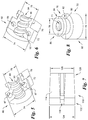
FIG. 5 is an enlarged perspective cut away view of a first nut body portion of the tension rod mechanism ofFIG. 1 showing the interior thereof; -
FIG. 6 is an enlarged perspective cut away view of the second nut body portion of the tension rod mechanism ofFIG. 1 showing the interior thereof; -
FIG. 7 is an elevational view of a wedge of the tension rod mechanism ofFIG. 1 ; and -
FIG. 8 is a right upper perspective view of a nut of the tension rod mechanism ofFIG. 1 . - Certain terminology is used in the following description for convenience only and is not limiting. The words “lower,” “bottom,” “upper,” “top,” “front,” “back,” and “rear” designate directions in the drawings to which reference is made. The words “inwardly” and “outwardly” refer to directions toward and away from, respectively, the geometric center of the component being discussed, and designated parts thereof, in accordance with the present disclosure. Unless specifically set forth herein, the terms “a,” “an,” and “the” are not limited to one element, but instead should be read as meaning “at least one.” The terminology includes the words noted above, derivatives thereof, and words of similar import.
- Referring to
FIGS. 1-4 , an example of atension rod 100 includes atension mechanism 10 for joining a firstouter shaft 20 and a secondinner shaft 30 of thetension rod 100. The firstouter shaft 20 has aninner surface 22, and the secondinner shaft 30 has aninner surface 32 and anend surface 34. The firstouter shaft 20 and the secondinner shaft 30 may be made from metal, a polymeric material such as plastic, wood, or some other suitable material. The secondinner shaft 30 is slidably received within the first outer shaft 20 (seeFIG. 3 ), such that thetension rod 100 is adjustable in length. Thetension rod 100 has alongitudinal axis 12, which is the example shown is common to the firstouter shaft 20, the firstinner shaft 30, and other elements as described below. - The
tension mechanism 100 comprises a partially threadedrod 40, which may be made from metal, a polymeric material such as plastic, wood, or some other suitable material, having a threadedportion 42, which has athread profile 56 having a constant inner and outer diameter between the first end and the second end thereof. Afirst end 44 extends from the threadedportion 42 and is adapted to be fixed to the secondinner shaft 30. Asecond end 46 is opposite to thefirst end 44. - The
first end 44 of the partially threadedrod 42 comprises acylindrical collar 62 having anexternal surface 66 with an outer diameter for engaging theinner surface 32 of the secondinner shaft 30 and a radially outwardly extendingflange 64 with an outer diameter for engaging theend surface 34 of the secondinner shaft 30. - The
second end 46 of the partially threadedrod 40 has a generally frusto-conical body 48, which is tapered and has afirst end 48 a, asecond end 48 b, a firstconical diameter 48 c at thefirst end 48 a, and a secondconical diameter 48 d at thesecond end 48 b. The secondconical diameter 48 d is larger than the firstconical diameter 48 c. - As used herein, a “generally frusto-conical shape” is a truncated conical shape having a longitudinal axis, a circular cross section perpendicular to the longitudinal axis, and sloped sides. A body that deviates from a geometrically perfect frusto-conical shape by having variation in the slope of the sides, deviations of less than 10 percent, measured radially, from a perfectly circular cross-section, or a rounded end, or other minor deviations from a geometrically ideal cone shape, is “generally frusto-conical.”
- As used herein, a “transverse dimension” of an element at a given point is the maximum dimension of that element, measured in a plane perpendicular to a longitudinal axis of the element and passing through the given point. Thus the frusto-
conical body 48 has a first transverse dimension (the firstconical diameter 48 c) at afirst point 52 along thelongitudinal axis 12 and a second transverse dimension (the secondconical diameter 48 d) at asecond point 54 along thelongitudinal axis 12. Thebody 48 may optionally have shapes other than frusto-conical—for example, a modified frusto-conical shape with one flat side. Thesecond point 54 is closer to thesecond end 48 b than to thefirst end 48 a, and the second transverse dimension (the secondconical diameter 48 d) is greater than the first transverse dimension (the firstconical diameter 48 c). Thesecond end 48 b of thebody 48 includes cylindrical aflange 60 having an outer diameter slidably fitted to theinner surface 22 of the firstouter shaft 20. Optionally thebody 48, the partially threadedrod 40, and thecylindrical collar 62 may be integrally formed as a single body without disconnectable parts. - Referring to
FIGS. 1, 3-6, and 8 , anut 70 has abore 71 and is threadedly engaged with the threadedportion 42 of the partially threadedrod 40. Thenut 70 is rotationally fixed to the firstouter shaft 20 so that upon rotation of the secondinner shaft 30 with respect to the firstouter shaft 20, the threadedportion 42 of the partially threadedrod 40 rotates with the secondinner shaft 30 such that thenut 70 is moved along thelongitudinal axis 12 by the partially threadedportion 42 toward thesecond end 46 of the partially threadedrod 40. Thenut 70 optionally may have afirst portion 72 having a firstouter diameter 74 and asecond portion 76 having a secondouter diameter 78. The firstouter diameter 74 may be slidably fitted to theinner surface 22 of the firstouter shaft 20, and the secondouter diameter 78 may be less than the firstouter diameter 74. Thesecond portion 76 may have aproximal end 80 adjacent the first portion, adistal end 82 opposite theproximal end 80, and a radially outwardly extendingdistal flange 84 adjacent thedistal end 82 of thesecond portion 76. Thenut 70 may optionally be formed from afirst nut body 86 and asecond nut body 92, which in the example shown are essentially two half-nuts. Thenut 70 may be made from metal, a polymeric material such as plastic, or other suitable material. Thefirst nut body 86 is aligned with and may be connected to thesecond nut body 92. Thefirst nut body 86 has a threaded half-bore 90, and thesecond nut body 92 has a threaded half-bore 96. Thefirst nut body 86 hasprotrusions 87 for engagingrecesses 93 of thesecond nut body 92, to align and connect thefirst nut body 86 to thesecond nut body 92. Screws, adhesives, or a snap fit may be used instead of or in addition to theprotrusions 87 and recesses 93 for aligning thefirst nut body 86 with thesecond nut body 92, connecting thefirst nut body 86 to thesecond nut body 92, or both. When connected together, thefirst nut body 86 and thesecond nut body 92 form thenut 70. Thefirst nut body 86 and thesecond nut body 92 when disconnected form twoopenings portion 42 of the partially threadedrod 40 to be introduced into thebore 71 of thenut 70. Thefirst nut body 86 and thesecond nut body 92 need not be half-nuts; alternatively first and second nut bodies may divide thenut 70 into unequal portions. - Referring to
FIGS. 1-4 and 7 , a wedge has a generally frusto-conical wedge body 110 having afirst end 122 with afirst wedge diameter 124 andsecond end 126 having asecond wedge diameter 128. Thewedge body 110 may be made from rubber or other suitable material. Thefirst end 122 and thesecond end 126 are aligned respectively with thefirst end 44 and thesecond end 46 of the partially threadedrod 40. - The
wedge body 110 has aninner surface 112 and anouter surface 114. Thefirst wedge diameter 124 is greater than thesecond wedge diameter 128. Theinner surface 112 is in facing sliding engagement with thebody 48 between thenut 70 and thesecond end 46 of the partially threadedrod 40. Thewedge body 110 includes alongitudinally extending slot 116, which may extend the entire length of thewedge body 110, or may extend only a portion of the length of thewedge body 110. Thewedge body 110 is in abutting engagement with thenut 70 so upon a movement of thenut 70 along the partially threadedrod 40, thewedge body 110 moves with thenut 70. Theinner surface 112 of thewedge body 110 may optionally comprise agroove 118 for engaging thedistal flange 84 of thesecond portion 76 of thenut 70. Thewedge body 110 is configured so that, upon theinner surface 112 of thewedge body 110 contacting thebody 48 as thewedge body 110 moves along thelongitudinal axis 12 from thefirst point 52 to thesecond point 54, thewedge body 110 expands radially outwardly and theouter surface 114 of thewedge body 110 makes contact with theinner surface 22 of the firstouter shaft 20, preventing relative movement between the firstouter shaft 20 and the secondinner shaft 30. - In use, the
tension rod 100 may be initially assembled with thetension mechanism 10 in an initial (or starting) configuration in which thenut 70 abuts or is proximate to thefirst end 44 of the partially threadedrod 42, where thecollar 62 is located. SeeFIG. 3 . The initial configuration allows the firstouter shaft 20 and the secondinner shaft 30 to slide telescopically relative to each other along thelongitudinal axis 12. A user thus adjusts a length of thetension rod 100 by sliding the firstouter shaft 20 and the secondinner shaft 30 with respect to one another along thelongitudinal axis 12 until thetension rod 100 is level between two support surfaces (not shown), with the ends (not shown) of the tension rod in contact with the two support surfaces. When the desired length is reached, the firstouter shaft 20 and the secondinner shaft 30 are rotated with respect to one another in a first direction, which causes thenut 70 to rotate with respect to the threadedportion 42 of therod 22, such that thenut 70 and thewedge body 110 move away from thefirst end 44 of the partially threadedrod 40 and toward thesecond end 46 and the generally frusto-conical body 48 of the partially threadedrod 40, as shown inFIG. 4 . As thewedge body 110 moves along the generally frusto-conical body 48, thewedge body 110 expands and applies an outwardly-directed radial force to the firstouter shaft 20, thus creating tension which locks the position of the secondinner shaft 30 relative to the firstouter shaft 20. - It will be appreciated by those skilled in the art that changes could be made to the embodiments described above without departing from the broad inventive concept thereof. It is understood, therefore, that this invention is not limited to the particular embodiments disclosed, but it is intended to cover modifications within the spirit and scope of the present disclosure as defined by the appended claims.
Claims (20)
Priority Applications (1)
| Application Number | Priority Date | Filing Date | Title |
|---|---|---|---|
| US16/106,849 US10995786B2 (en) | 2018-08-21 | 2018-08-21 | Tension rod mechanism |
Applications Claiming Priority (1)
| Application Number | Priority Date | Filing Date | Title |
|---|---|---|---|
| US16/106,849 US10995786B2 (en) | 2018-08-21 | 2018-08-21 | Tension rod mechanism |
Publications (2)
| Publication Number | Publication Date |
|---|---|
| US20200063774A1 true US20200063774A1 (en) | 2020-02-27 |
| US10995786B2 US10995786B2 (en) | 2021-05-04 |
Family
ID=69584457
Family Applications (1)
| Application Number | Title | Priority Date | Filing Date |
|---|---|---|---|
| US16/106,849 Expired - Fee Related US10995786B2 (en) | 2018-08-21 | 2018-08-21 | Tension rod mechanism |
Country Status (1)
| Country | Link |
|---|---|
| US (1) | US10995786B2 (en) |
Cited By (3)
| Publication number | Priority date | Publication date | Assignee | Title |
|---|---|---|---|---|
| WO2022037810A1 (en) * | 2020-08-19 | 2022-02-24 | Tds Gmbh | Tensioning device for tensioning tensioning means such as chains, straps, ropes or the like |
| US12082732B2 (en) | 2020-11-25 | 2024-09-10 | Decolin Inc. | Adjustable telescoping tension rods |
| US20260090530A1 (en) * | 2024-10-01 | 2026-04-02 | Jaime Buice | Systems, methods, and assemblies for providing a paddle with a stowed ready-to-use spear |
Families Citing this family (11)
| Publication number | Priority date | Publication date | Assignee | Title |
|---|---|---|---|---|
| US10959559B2 (en) | 2019-03-08 | 2021-03-30 | House of Atlas, LLC | Dual-mounted end cap system and locking system for an adjustable rod |
| US11382447B2 (en) | 2019-07-30 | 2022-07-12 | House of Atlas, LLC | Adjustable rod features |
| IT201900003638U1 (en) * | 2019-10-14 | 2021-04-14 | Fimm Italia S P A | IMPROVED COMPONIBLE TUBE. |
| US11825940B2 (en) | 2020-05-18 | 2023-11-28 | House of Atlas, LLC | Customizable shower caddy |
| GB202109832D0 (en) * | 2021-07-07 | 2021-08-18 | Hebe Studio Ltd | Connector |
| US12108901B2 (en) * | 2021-12-14 | 2024-10-08 | Dongguan Shenghong Household Items Co., Ltd. | Internal locking retractable shower curtain rod and connector |
| US11974704B2 (en) | 2022-03-03 | 2024-05-07 | House Of Atlas Llc | Customizable shower caddy |
| USD1019367S1 (en) * | 2023-09-22 | 2024-03-26 | Qingyun LI | Spring fixed telescopic device |
| USD1019366S1 (en) * | 2023-09-22 | 2024-03-26 | Qingyun LI | Connector |
| US12303053B1 (en) | 2023-11-14 | 2025-05-20 | House of Atlas, LLC | Spring-biased end caps for rod assembly and methods of use |
| US20250268412A1 (en) * | 2024-02-22 | 2025-08-28 | Sumeet Jain | Extendable rod with a twist lock mechanism |
Family Cites Families (29)
| Publication number | Priority date | Publication date | Assignee | Title |
|---|---|---|---|---|
| US520584A (en) | 1894-05-29 | Adjustable curtain-rod | ||
| US1679881A (en) | 1925-10-05 | 1928-08-07 | Herbert A Simpson | Hanger rod |
| US2661850A (en) | 1950-02-23 | 1953-12-08 | William E Fowler | Curtain rod |
| US3004743A (en) * | 1958-09-15 | 1961-10-17 | Harry J Wenger | Music stands |
| GB1578159A (en) * | 1976-09-22 | 1980-11-05 | Wolf Geraete Gmbh | Connector |
| USD260074S (en) | 1979-09-26 | 1981-08-04 | Ray Lewis & Son, Inc. | Combined adjustable curtain rod holder and rod |
| US5433551A (en) | 1994-01-12 | 1995-07-18 | Gordon; Larry D. | Telescoping rod assembly |
| US6202663B1 (en) * | 1999-08-09 | 2001-03-20 | Crystal Industrial Co., Ltd. | Stick-used stageless adjusting device |
| US6302614B1 (en) | 2000-02-17 | 2001-10-16 | Yun-Chih Tseng | Quick coupling arrangement for a telescopic shaft |
| ITMI20051441A1 (en) * | 2005-07-26 | 2007-01-27 | Pronzati Giuseppe Gipron Spa | TUBE LOCKING SYSTEM |
| USD548579S1 (en) | 2005-10-05 | 2007-08-14 | Powers Products Iii, Llc | Expansion anchor |
| DE102006008515A1 (en) * | 2006-02-23 | 2007-09-06 | Sports-Ace International Co., Ltd. | Stick with adjustable length to act as a staff has an internal tube in an external tube so as to rotate and move on axis as well as a ringed stopper, a longitudinal slot and a cone-shaped wall |
| KR100768638B1 (en) * | 2006-12-05 | 2007-10-18 | 손대업 | Stick connector |
| WO2009039578A1 (en) * | 2007-09-28 | 2009-04-02 | Walter Peter Wright | Improved internal locking device for extendable telescoping poles |
| SE532870C2 (en) * | 2008-02-16 | 2010-04-27 | Fast Industriprodukter Hb | Locking means for telescopically arranged elements, including axially directed threads |
| US8827587B2 (en) | 2010-12-17 | 2014-09-09 | Zenith Products Corporation | Tension rod mechanism with opposing threads |
| US8851305B2 (en) | 2010-12-17 | 2014-10-07 | Zenith Products Corporation | Unidirectional tension rod mechanism |
| US8960456B2 (en) | 2010-12-17 | 2015-02-24 | Zenith Products Corporation | Molded tension rod mechanism with single lock nut |
| US8851435B1 (en) * | 2011-03-15 | 2014-10-07 | Kenney Manufacturing Co. | Rod assembly with reversible locking device |
| US20120284914A1 (en) * | 2011-05-13 | 2012-11-15 | Bauer Alan M | Tension rod |
| CH706752A1 (en) * | 2012-07-19 | 2014-01-31 | Lekisport Ag | Length adjustable pipe, especially for sticks. |
| US9107529B2 (en) | 2012-11-14 | 2015-08-18 | Zenith Products Corporation | Adjustable tension-mounted curved rod assembly |
| US20160206126A1 (en) * | 2013-03-13 | 2016-07-21 | House of Atlas, LLC | Adjustable Tension Rod |
| US20140263123A1 (en) | 2013-03-13 | 2014-09-18 | House of Atlas, LLC | Adjustable Tension Rod |
| US9388837B1 (en) * | 2013-07-10 | 2016-07-12 | Kenney Manufacturing Company | Telescoping tube assembly having twist lock |
| US10047787B2 (en) * | 2016-08-16 | 2018-08-14 | Li-Ming Cheng | Tension rod mechanism |
| US10070748B2 (en) * | 2016-09-08 | 2018-09-11 | Kenney Manufacturing Co. | Curtain rod bracket and cam lock |
| US10844890B2 (en) * | 2017-11-16 | 2020-11-24 | Liberty Hardware Mfg. Corp. | Locking telescoping rod |
| US10426287B1 (en) * | 2017-11-22 | 2019-10-01 | Abo Window Fashion Corp. | Curtain rod |
-
2018
- 2018-08-21 US US16/106,849 patent/US10995786B2/en not_active Expired - Fee Related
Cited By (4)
| Publication number | Priority date | Publication date | Assignee | Title |
|---|---|---|---|---|
| WO2022037810A1 (en) * | 2020-08-19 | 2022-02-24 | Tds Gmbh | Tensioning device for tensioning tensioning means such as chains, straps, ropes or the like |
| CN116249839A (en) * | 2020-08-19 | 2023-06-09 | Tds有限公司 | Tensioning device for tensioning a tensioning mechanism such as a chain, belt, rope or the like |
| US12082732B2 (en) | 2020-11-25 | 2024-09-10 | Decolin Inc. | Adjustable telescoping tension rods |
| US20260090530A1 (en) * | 2024-10-01 | 2026-04-02 | Jaime Buice | Systems, methods, and assemblies for providing a paddle with a stowed ready-to-use spear |
Also Published As
| Publication number | Publication date |
|---|---|
| US10995786B2 (en) | 2021-05-04 |
Similar Documents
| Publication | Publication Date | Title |
|---|---|---|
| US10995786B2 (en) | Tension rod mechanism | |
| KR102058490B1 (en) | Length-adjustable tube, in particular for sticks | |
| US9651073B2 (en) | Locking mechanism for telescoping members | |
| RU2682354C2 (en) | Folding stick with a tubular sleeve | |
| US7044953B2 (en) | Compression bone screw | |
| US6843183B2 (en) | System and method for enhanced telescoping engagement | |
| US6250839B1 (en) | Length-adjustable tube, specially for ski poles or walking sticks | |
| ES2924258T3 (en) | Bearing | |
| US20160271813A1 (en) | Joint | |
| US7413369B2 (en) | Lock pin with pushbutton-operated axial locking and free bearing | |
| US291282A (en) | Lathe mandbel | |
| US20060230581A1 (en) | Locking mechanism for an extension pole | |
| US20030213330A1 (en) | Locating/controlling structure for telescopic tube | |
| US4473918A (en) | Pivot handle for dust mops and the like | |
| US20180318870A1 (en) | Caulking gun | |
| EP2948082B1 (en) | Limited collapse surgical screws | |
| JP2003239923A (en) | Pole with joining screw | |
| JP7325080B2 (en) | Joining means and joining method of members | |
| KR20200005052A (en) | Hinge having controllable asymmetry torque | |
| WO2017137696A1 (en) | Writing instrument with self-blocking assembly. | |
| US20170282803A1 (en) | View angle adjustment mechanism in view device | |
| KR102053531B1 (en) | Pre-load telescoping tube | |
| US92860A (en) | Improvement in shaft-coupling | |
| EP4732713A1 (en) | Glide bearing device for a height adjustable column and height adjustable column | |
| US942093A (en) | Joint for artificial limbs. |
Legal Events
| Date | Code | Title | Description |
|---|---|---|---|
| FEPP | Fee payment procedure |
Free format text: ENTITY STATUS SET TO UNDISCOUNTED (ORIGINAL EVENT CODE: BIG.); ENTITY STATUS OF PATENT OWNER: SMALL ENTITY |
|
| FEPP | Fee payment procedure |
Free format text: ENTITY STATUS SET TO SMALL (ORIGINAL EVENT CODE: SMAL); ENTITY STATUS OF PATENT OWNER: SMALL ENTITY |
|
| STPP | Information on status: patent application and granting procedure in general |
Free format text: NOTICE OF ALLOWANCE MAILED -- APPLICATION RECEIVED IN OFFICE OF PUBLICATIONS |
|
| STPP | Information on status: patent application and granting procedure in general |
Free format text: PUBLICATIONS -- ISSUE FEE PAYMENT RECEIVED |
|
| STPP | Information on status: patent application and granting procedure in general |
Free format text: PUBLICATIONS -- ISSUE FEE PAYMENT VERIFIED |
|
| STCF | Information on status: patent grant |
Free format text: PATENTED CASE |
|
| FEPP | Fee payment procedure |
Free format text: MAINTENANCE FEE REMINDER MAILED (ORIGINAL EVENT CODE: REM.); ENTITY STATUS OF PATENT OWNER: SMALL ENTITY |
|
| LAPS | Lapse for failure to pay maintenance fees |
Free format text: PATENT EXPIRED FOR FAILURE TO PAY MAINTENANCE FEES (ORIGINAL EVENT CODE: EXP.); ENTITY STATUS OF PATENT OWNER: SMALL ENTITY |
|
| STCH | Information on status: patent discontinuation |
Free format text: PATENT EXPIRED DUE TO NONPAYMENT OF MAINTENANCE FEES UNDER 37 CFR 1.362 |
|
| FP | Lapsed due to failure to pay maintenance fee |
Effective date: 20250504 |