US2363779A - Hose actuated press - Google Patents
Hose actuated press Download PDFInfo
- Publication number
- US2363779A US2363779A US448449A US44844942A US2363779A US 2363779 A US2363779 A US 2363779A US 448449 A US448449 A US 448449A US 44844942 A US44844942 A US 44844942A US 2363779 A US2363779 A US 2363779A
- Authority
- US
- United States
- Prior art keywords
- hose
- frame
- press
- secured
- platens
- Prior art date
- Legal status (The legal status is an assumption and is not a legal conclusion. Google has not performed a legal analysis and makes no representation as to the accuracy of the status listed.)
- Expired - Lifetime
Links
- 239000003292 glue Substances 0.000 description 9
- 210000002445 nipple Anatomy 0.000 description 4
- 230000000903 blocking effect Effects 0.000 description 3
- 230000006835 compression Effects 0.000 description 3
- 238000007906 compression Methods 0.000 description 3
- 230000004048 modification Effects 0.000 description 3
- 238000012986 modification Methods 0.000 description 3
- 238000003466 welding Methods 0.000 description 3
- 238000010276 construction Methods 0.000 description 2
- 238000006073 displacement reaction Methods 0.000 description 2
- 238000010438 heat treatment Methods 0.000 description 2
- 210000003141 lower extremity Anatomy 0.000 description 2
- 239000002023 wood Substances 0.000 description 2
- 238000004026 adhesive bonding Methods 0.000 description 1
- 229940089918 ansaid Drugs 0.000 description 1
- 239000010425 asbestos Substances 0.000 description 1
- 230000008901 benefit Effects 0.000 description 1
- 230000005540 biological transmission Effects 0.000 description 1
- 230000008859 change Effects 0.000 description 1
- 230000008878 coupling Effects 0.000 description 1
- 238000010168 coupling process Methods 0.000 description 1
- 238000005859 coupling reaction Methods 0.000 description 1
- 230000002950 deficient Effects 0.000 description 1
- 210000003414 extremity Anatomy 0.000 description 1
- SYTBZMRGLBWNTM-UHFFFAOYSA-N flurbiprofen Chemical compound FC1=CC(C(C(O)=O)C)=CC=C1C1=CC=CC=C1 SYTBZMRGLBWNTM-UHFFFAOYSA-N 0.000 description 1
- 239000007788 liquid Substances 0.000 description 1
- 239000002184 metal Substances 0.000 description 1
- 230000002093 peripheral effect Effects 0.000 description 1
- 229920000136 polysorbate Polymers 0.000 description 1
- 230000008439 repair process Effects 0.000 description 1
- 230000000717 retained effect Effects 0.000 description 1
- 229910052895 riebeckite Inorganic materials 0.000 description 1
Images


Classifications
-
- B—PERFORMING OPERATIONS; TRANSPORTING
- B30—PRESSES
- B30B—PRESSES IN GENERAL
- B30B1/00—Presses, using a press ram, characterised by the features of the drive therefor, pressure being transmitted directly, or through simple thrust or tension members only, to the press ram or platen
- B30B1/003—Presses, using a press ram, characterised by the features of the drive therefor, pressure being transmitted directly, or through simple thrust or tension members only, to the press ram or platen by an elastic bag or diaphragm expanded by fluid pressure
-
- B—PERFORMING OPERATIONS; TRANSPORTING
- B27—WORKING OR PRESERVING WOOD OR SIMILAR MATERIAL; NAILING OR STAPLING MACHINES IN GENERAL
- B27D—WORKING VENEER OR PLYWOOD
- B27D3/00—Veneer presses; Press plates; Plywood presses
Definitions
- a hose actuated press principal object a means by uniformly distributed over the platens carried and exercised by in the press a pair of platens horizontally disposed and vertically aligned with respect to their peripheral edges, and between which glue jointed work is placed to be pressed and heated when the power is applied to the press through the medium of fire hose sections distributed beneath the lower platen, the fire hose seating on a support adjustably arranged in the construction of the press, and means to inflate all of the fire hose sections simultaneously, hydraulically or pneumatically.
- a still further object of this invention is to provide a channel for each hose to maintain straight alignment thereof, and an equal dis,-
- each channel may be of suflicient depth to stack a plurality b1 hose therein; in will be divided by a plate to float with the vertical movement of the hose and to avoid side displacement of the hose from vertical alignment with each other.
- a further object of our invention is to provide a gauge to automatically control a predetermined pressure between said platens.
- a still further object of our invention is to provide an'eflicient heating means for the press platens, said means to be optionally. exercised with respect to heating the platens. 7
- a further object of our invention is to provide a simple and eflicient press whereby, gluing together the components of wood structures is easily and quickly'accomplished with respect to setting the glue rapidly and forcing the Joints to snug engagement.
- FIG. 5 is an enlarged cross section of the hose
- Fig. 6 is a modification to illustrate the stacking of the fire hose.
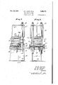
- Fig. '7 is a sectional view longitudinally of'the press modified to illustrate a different application of the hose.
- Fig. 8 is a sectional view taken on line 8'8 in Fig. 7.
- Fig. 9 is an end view of a narrow press partly in section.
- Fig. 10 is an end view of a narrow press modifled for a greater width than that shown in Fig. 9.
- Figs. sists of a lower frame I rectangular in form and consisting of I-beams for the sides and nds of the frame, said beams being welded tog er.
- FIG. 4 is enlarged side view of the hose and its channel, parts removed for convenience of illustration.v
- said adjustable frame Upon said adjustable frame ismounted a floating. frame, said frame comprising a, plate 1 seating on the upper side of said adjustable frame, the comers of said plate being drilled in like manner to engage on the corner posts whereby a continuous bearing is provided across the, adjustable frame, and upon whichv lengths of L-shaped members I are placed in juxtaposition to form a plurality of channels extending from end to end of the press frame and of sufficient number to fill the space-from side to side of the press substantially as shown in Fig. 3.
- each channel is a length or fire hose 4 9, the terminating ends of. which extend outward a short distance from their respective channels as shown in Fig. 4, said terminal ends being collapsed and clamped together simultaneously by a pair of bars Ill transversely to the fire hose v thereto by a coupling IS, the flexible hose being means to permit vertical movement of the movable frame, said flexible hose extending to and beingconnected to a source of supply later described.
- the said pipe l2 has a plurality of' laterals-16 extending therefrom to communicate with the corresponding-ends of the hose, as
- a nipple I8 the upper endof which is provided with an annular flange C to bind the hose seating on an annular washer IS, the latter having an abrupt upper extension D to embed in the hose 1 to avoid expansion from its aperture through which the nipple extends, said washer seating on the said leg of the said, l -shaped member 8 that rests on the plate.
- Each flre hose has a plate 2
- Each corner of said sheet is drilled to likewise slidably engage on said corner similar to that shown in Fig. 3, said work being pressed for tight engagement of the glued joints as well as being heated by the platens ;for quick setting and hardening of the glue, the
- platens being heated by steam injected therein through a supply pipe ill].
- whereby the steam is free to circulate through the platens.
- platen 24 is arranged to move vertically for clamping purpose
- a flexible pipe 32 for the supply and the exhaust, while the upper platen 25 being stationarily secured to the top frame has a-rigid pipe connection 33.
- a compression tank 34 Positioned in working relationto the flre hose 5 sections is a compression tank 34 vertically disposed, said tank having a supply pipe 35 communicatlng therewith at its upper end, the pipe connecting the tank with a source of supply and having a valve 36 therein as controlling means for the supply.
- a supply pipe 31 for the fire hose said supply extending upward from the tank and communicating with a pressure regulator 38, the pressure flow being controlled by a T-element 29 as adjusting means for the pressure, said pressure being recorded by .a gauge 40 to certain pressure imposed in the 'flre hose.
- T re is also provided a three-way valve 4
- the flre hose sections may be stacked plurally similar to that shown in Fig. 6, the hose sections being separated by a plate 2
- The, press actuated by the fire may vary in' size and construction to accommodate for special kind of workyfor'example,
- the structure of'Figs. 7 and 8 consistsof a pair of I-beams spaced apart in parallelism torunction as abase for the press, said I-lbeams' being secured in spaced relation at their lower extremity by a plate 44'-a djac ent each end of the be while the u r extremity thereof is secu ed together by a plate 45 extending longitudinally of the beams terminating a spaced distance inward from each end thereof.
- the said I-beamseach are bored through their upper legs a spaced distance inward from their outer ends to receive corner posts 46 insertible therein, and secured by welding, each post being shouldered 0 a spaced distance upward by reducing the same 1 in diameter as shown in Fig.
- hose sections the lower legs of I-beams 41 will seat, it. being frame comprised of bars Ill for the sides and ends said channel is bored adjacent each of itscomers to slidably engage on the posts when vertically moved by inflation or deflation on the fire hose.
- a hollow platen 56 Secured to'the upper side of the channel and movable therewith is a hollow platen 56 that reg isters in vertical alignment with the first said platen and between which glue jointed work may be placed to clamp the joints to snug engagement and cause the glue to set quickly by heat dispensed from the hollow platens, it being understood that the platens and fire hose have similar supply and exhaust arrangement to that described for the hose and platens in Figs. 1 and 2.
- a modification of the press shown in Fig. 9 is adaptalble for rpressing glued feathered jointed plies of wood 51 together, and in this instance, the upper and lower framemembers 58 and 59 respectively are secured in spaced relation by apost 60 at each end of the
- a pair of platens 63 and 64 are suitably secured to the upper and lower portions of the fram respectively, said platens confronting each other, the lower platen seating on a metal plate 65'to which it is secured, the ends of which extend outward from the platen and being bored to slidably engage on the posts, the plate being carried by a timber 66 as an adjusting element by varying the thickness thereof vertically, said timber to move vertically in a channel 61 formed on the top of the frame member 59 as actuated by a pair of fire hose 9 seated in the channel beneath the timber, and
- the press illustrated in Figs. 10 and 11 con- 50 sists of a base plate 68 rectangular in form, and having secured theretoadjacent each of its corners a threaded post 69 extending upward therefrom, thetop of the posts lbeing connected by a thereof, also intermediate bars crossing the frame as supporting means for a hub II centrally disposed within the bar portions 'lll of the frame, said hub, being axially bored and threaded to carry a threaded screw element 12 on which 60 is secured a wheel 13, the screw as pendent carrying means for the press floating head that is comprisedof a similar frame to that above described but having a (bearing plate 14 to close the lower portion of the frame.
- the said frame has a sleeve 15 at each comer thereof to slidably engage on their respective posts, and the said frame being secured against upward movement when located, selectively, at a desired point vertically of the press by a threaded wheel nut 16 for each 70 post, whereby said plate H is secured a spaced distance upward from another floating plate 11, the corners of which are notched to slidably engage on said corner posts to avoid lateral displacement in its vertical movement, said move- 76 and to meet the hose sections lengths of fire hose juxsuflicient number to cov the ment being actuated by taposition'ed and in inner confronting area of last said plate and base plate 68 on which said flre hose seats, said fire hose being connected to a source for compresa sion similar to that heretofore described.
- a frame comprised of upper and lowerrectangular members spaced apart and being connected-by posts, a, pair of rectangular members positioned in the frame between first said rectangular members, said pair of rectangular members adapted'to slidably engage on the posts towardand from their respective upper and lower rectangular members, a plurality of fire hose sections arranged to move one of said second rectangular memberstoward the upper rectangular member, and means to inflate the plurality of fire hose sections simultaneously.
- a fire hose actuated press of the class described comprising upper and lower frames, each of said frames being rectangular in form, and a post for each corresponding corner of the frames to secure the same in spaced relation vertically, andanother rectangular frame positioned between the said upper and lower frames, said other frame adapted to move vertically and being guided by the.
- corner posts blocking positioned on the lower frame to adjustably carry I the said other frame, a vertically floating frame positioned above said other frame, the floating frame being guided by the corner posts, a plurality of channels placed side by side between the said other frame and said floating frame, each channel having fire hose sections stacked therein to move the floating frame toward the upper frame, and pipe and valve means to connect the fire hose sections to a pressure supply to inflate and deflate said hose sections for the purpose specified.
- a lower frame and an upper frame horizontally disposed and spaced apart, said frames being secured together by vertically disposed posts extending through each frame and welded thereto, a rectangular frame having each corner bored to slidably engage on the corner posts, a rectangular plate positioned above last said frame and having its corners bored to slidably engage on the posts, a plurality of L-shaped members in juxtaposition to form a series of channels one way across the slidable rectangular frame and terminating the other waya spaced distance inward of thesaid.
- said channels each having a fire hose section positioned therein, extending there'along and outward from each end of the channels,
- channel means to carry the plate and being I y insertible in first said channels against which is impounded compression from the host sections prior to maximum inflation of said hose sections means to clamp .bothfends of eachflre hose section together air tight, pipe means to connect the flre hose sections simultaneously to a source of pressure to inflate the same and a suitable valvev to inject pressure for the hose sections.
- channelv comprising a web. and legs extendin outward from one side of the web, a plurality of hose sections vertically stacked in the channel and plates placed between the said hose sections, said plates adapted to float vertically between the legs of the channel as the hose sections are being inflated, and power means to inflate the hose sections for the purpose specifled.
Landscapes
- Engineering & Computer Science (AREA)
- Mechanical Engineering (AREA)
- Life Sciences & Earth Sciences (AREA)
- Physics & Mathematics (AREA)
- Fluid Mechanics (AREA)
- Wood Science & Technology (AREA)
- Forests & Forestry (AREA)
- Veneer Processing And Manufacture Of Plywood (AREA)
- Building Environments (AREA)
Description
Nov. 28, 19 44. in. H. DUFFY ,ET AL HOSE AC TUATED PRESS Filed June 25, 1942 4 Sheets-Sheet 2 .0. [2C DUF'FY J. TA/I W11. E'Y M A 05 3 IN VENTORS',
Nov. 28, 1944; J D. H. DUFFY ET AL HOSE ACTUATED PRESS Filed June 25, 1942 4 Sheets-Sheet s D. H DvPFY r]. W VVJLEY MMHOs's INVENTORS.
Nov. 28, 1944. D. H. DUFFY ET AL 2,363,779
HOSE ACTUATED PRESS Filed June 25; 1942 4 Sheets-Sheet 4 F1948 Flt/.10
' this event the hose sections Patented Nov. 28, 1944 UNITED. STATES PATENT" OFFICE HOSE A3322 rREss 7 Damn. Duffy,
James W. Wiley, and Milburn M.
Ross, Wichita, Kans., assignors to Beech Aircraft Corporation, Wichita, Kans.,
tion of Delaware a corpora-Q Application June 25, 1942, Serial No. 448,449
Claims. (01. 144-281) a hose actuated press, principal object a means by uniformly distributed over the platens carried and exercised by in the press a pair of platens horizontally disposed and vertically aligned with respect to their peripheral edges, and between which glue jointed work is placed to be pressed and heated when the power is applied to the press through the medium of fire hose sections distributed beneath the lower platen, the fire hose seating on a support adjustably arranged in the construction of the press, and means to inflate all of the fire hose sections simultaneously, hydraulically or pneumatically.
' A still further object of this invention is to provide a channel for each hose to maintain straight alignment thereof, and an equal dis,-
tribution of pressure across the platens, and
furthermore each channel may be of suflicient depth to stack a plurality b1 hose therein; in will be divided by a plate to float with the vertical movement of the hose and to avoid side displacement of the hose from vertical alignment with each other.
A further object of our invention is to provide a gauge to automatically control a predetermined pressure between said platens.
A still further object of our invention is to provide an'eflicient heating means for the press platens, said means to be optionally. exercised with respect to heating the platens. 7
A further object of our invention is to provide a simple and eflicient press whereby, gluing together the components of wood structures is easily and quickly'accomplished with respect to setting the glue rapidly and forcing the Joints to snug engagement. I
These and; other objects will hereinafter be required for the work carried 'Fig. 5 is an enlarged cross section of the hose,
its channel and hose pipe connection.
. Fig. 6 is a modification to illustrate the stacking of the fire hose.
, Fig. '7 is a sectional view longitudinally of'the press modified to illustrate a different application of the hose.
Fig. 8 is a sectional view taken on line 8'8 in Fig. 7.
Fig. 9is an end view of a narrow press partly in section.
Fig. 10 is an end view of a narrow press modifled for a greater width than that shown in Fig. 9.
, The press disclosed in Figs. sists of a lower frame I rectangular in form and consisting of I-beams for the sides and nds of the frame, said beams being welded tog er.
where they, meet at the corners, the upper leg ,A at each corner being drilled to receive acorner post 2 slidable therethrough and seating on tremity by a frame 3 similar to that of thelower frame, said frames and comer posts being secured rigidly by welding the same together.
'7 other similar frame 4 to that above described, 1
Slidably mounted on the (former posts' is ansaid frame beingdrilled at its corners to slidably engage on the said'comer posts whereby a bed is formed for vertical a ustment to carry the load of compression when the press is energizeg, the last said frafne to be secured a predetermined spaced distance from the lower frame by suitable blocking 5 and 6 as shown, or
' otherwise, spaced along the sides and ends of more fully explained, reference being had to press, partly Fig. 4 is enlarged side view of the hose and its channel, parts removed for convenience of illustration.v
the said beam elements. Upon said adjustable frame ismounted a floating. frame, said frame comprising a, plate 1 seating on the upper side of said adjustable frame, the comers of said plate being drilled in like manner to engage on the corner posts whereby a continuous bearing is provided across the, adjustable frame, and upon whichv lengths of L-shaped members I are placed in juxtaposition to form a plurality of channels extending from end to end of the press frame and of sufficient number to fill the space-from side to side of the press substantially as shown in Fig. 3.
Seating in each channel is a length or fire hose 4 9, the terminating ends of. which extend outward a short distance from their respective channels as shown in Fig. 4, said terminal ends being collapsed and clamped together simultaneously by a pair of bars Ill transversely to the fire hose v thereto by a coupling IS, the flexible hose being means to permit vertical movement of the movable frame, said flexible hose extending to and beingconnected to a source of supply later described. The said pipe l2 has a plurality of' laterals-16 extending therefrom to communicate with the corresponding-ends of the hose, as
shown in Figs. 2 and 4, the laterals each having aunion H whereby a defective hose length may be removed for repairs or'replacement by a new length of hose. The connection of the hose from the union upward is through the medium of a nipple I8, the upper endof which is provided with an annular flange C to bind the hose seating on an annular washer IS, the latter having an abrupt upper extension D to embed in the hose 1 to avoid expansion from its aperture through which the nipple extends, said washer seating on the said leg of the said, l -shaped member 8 that rests on the plate. I, said leg, plate, and leg of the I-beam 4 being drilled in registry and through whichjhe nipple extends and being tensioned by a nut 20 threadedly engaging thereon to secure the nipple air and liquid tight where it engages with the hose. It will now be seen how the hose lengths are removably conn d to'the press and communicating with the so cc of supply, pneumatically or hydraulically.
Each flre hose has a plate 2| positioned thereon to slidably engage vertically in the'channel thus provided, and each plate hasa channel 22 lying thereon with its legs upwardly extending,
and on which is secured a metallic sheet 28 tov cover the area between the corner posts. It will be seen that the legs of the channels thus formed will function as astqp to carry the load of the sheet 23, and a platen later described when the hose sections are collapsed by disengaging the pressure; furthermore there is provided short lengths of pipes 8 vertically secured to plate I to coact with the channellegs to carry the weight of said sheet and platen when released by collapsing the hose.
posts, whereby lateral movementbf said plate is obviated and adapted .to carry a hollow platen 24 seated thereon, said platen being in vertical registry with another platen 25 that is secured to the upper frame, the platens being secured to their respectivecarrying members by an L- shaped member 26 positioned at each end of each platen through" the medium of bolts 26' whereby the platens are likewise secured against lateral inovement when functioning as compressing elements, both of said platens being insulated from the elements'of the press byan asbestos sheet 21 to avoid free transmission or heat to the hose whereby excess expansion of air compressed will 1 be eliminated when the platens are heated.
The plates above referred to are the elements between which glue joined work 28 is placed,
Each corner of said sheet is drilled to likewise slidably engage on said corner similar to that shown in Fig. 3, said work being pressed for tight engagement of the glued joints as well as being heated by the platens ;for quick setting and hardening of the glue, the
platens being heated by steam injected therein through a supply pipe ill]. There is also provided an exhaust through pipe 3| whereby the steam is free to circulate through the platens. Inasmuch as platen 24 is arranged to move vertically for clamping purpose there is provided a flexible pipe 32 for the supply and the exhaust, while the upper platen 25 being stationarily secured to the top frame has a-rigid pipe connection 33.
Positioned in working relationto the flre hose 5 sections is a compression tank 34 vertically disposed, said tank having a supply pipe 35 communicatlng therewith at its upper end, the pipe connecting the tank with a source of supply and having a valve 36 therein as controlling means for the supply. There is also provided a supply pipe 31 for the fire hose, said supply extending upward from the tank and communicating with a pressure regulator 38, the pressure flow being controlled by a T-element 29 as adjusting means for the pressure, said pressure being recorded by .a gauge 40 to certain pressure imposed in the 'flre hose. T re is also provided a three-way valve 4| to make and break the flow leading to the fire hose and also as an exhaust for the hose through pipe 42.
The flre hose sections may be stacked plurally similar to that shown in Fig. 6, the hose sections being separated by a plate 2| heretofore described, the purpose of which is for the advantage of a greater vertical movement of the lower platen whereby the space between the stationary platen and the movable'platen may be increased for the convenience of installing work between said platens that may vary in height 40 without change of the blocking 5 and- B to vary the space between the platens.
The, press actuated by the fire may vary in' size and construction to accommodate for special kind of workyfor'example,
we have illustrated modiflcations'in Figs. '7 to 11 inclusive.
The structure of'Figs. 7 and 8 consistsof a pair of I-beams spaced apart in parallelism torunction as abase for the press, said I-lbeams' being secured in spaced relation at their lower extremity by a plate 44'-a djac ent each end of the be while the u r extremity thereof is secu ed together by a plate 45 extending longitudinally of the beams terminating a spaced distance inward from each end thereof The said I-beamseach are bored through their upper legs a spaced distance inward from their outer ends to receive corner posts 46 insertible therein, and secured by welding, each post being shouldered 0 a spaced distance upward by reducing the same 1 in diameter as shown in Fig. '7, and upon which understood that the upper and lower legs of said beams are bored in vertical registry for the corner posts and sli-dalble thereon but removably se curedby nut 48 threadedly enga ing on their respective posts that extends through the upper leg of the I-beam, each side of thelast said I-beam being enclosed by a plate 49 fitting be 7 tween the outside portion of the legs and secured thereto by welding, whereby an upper portion 0 of the press frameis formed and secured in spacedrelation from the base; .Said upper portion'has a spacing plank I0 and a hollow platen II secured at its lower extremity by bolts 52;
hose sections the lower legs of I-beams 41 will seat, it. being frame comprised of bars Ill for the sides and ends said channel is bored adjacent each of itscomers to slidably engage on the posts when vertically moved by inflation or deflation on the fire hose. Secured to'the upper side of the channel and movable therewith is a hollow platen 56 that reg isters in vertical alignment with the first said platen and between which glue jointed work may be placed to clamp the joints to snug engagement and cause the glue to set quickly by heat dispensed from the hollow platens, it being understood that the platens and fire hose have similar supply and exhaust arrangement to that described for the hose and platens in Figs. 1 and 2. A modification of the press shown in Fig. 9 is adaptalble for rpressing glued feathered jointed plies of wood 51 together, and in this instance, the upper and lower framemembers 58 and 59 respectively are secured in spaced relation by apost 60 at each end of the frame members, the
' lower portion of the frame seating on a suitable base 6|, the end elevation of which is shown in Fig.--9 and to which the posts are attached, each post being secured by nuts 62, one being above and one belowthe base. A pair of platens 63 and 64 are suitably secured to the upper and lower portions of the fram respectively, said platens confronting each other, the lower platen seating on a metal plate 65'to which it is secured, the ends of which extend outward from the platen and being bored to slidably engage on the posts, the plate being carried by a timber 66 as an adjusting element by varying the thickness thereof vertically, said timber to move vertically in a channel 61 formed on the top of the frame member 59 as actuated by a pair of fire hose 9 seated in the channel beneath the timber, and
the said hollow platens and fire hose sections being energized for their respective service similar to that described for Figs. 1 and 2.
The press illustrated in Figs. 10 and 11 con- 50 sists of a base plate 68 rectangular in form, and having secured theretoadjacent each of its corners a threaded post 69 extending upward therefrom, thetop of the posts lbeing connected by a thereof, also intermediate bars crossing the frame as supporting means for a hub II centrally disposed within the bar portions 'lll of the frame, said hub, being axially bored and threaded to carry a threaded screw element 12 on which 60 is secured a wheel 13, the screw as pendent carrying means for the press floating head that is comprisedof a similar frame to that above described but having a (bearing plate 14 to close the lower portion of the frame. The said frame has a sleeve 15 at each comer thereof to slidably engage on their respective posts, and the said frame being secured against upward movement when located, selectively, at a desired point vertically of the press by a threaded wheel nut 16 for each 70 post, whereby said plate H is secured a spaced distance upward from another floating plate 11, the corners of which are notched to slidably engage on said corner posts to avoid lateral displacement in its vertical movement, said move- 76 and to meet the hose sections lengths of fire hose juxsuflicient number to cov the ment being actuated by taposition'ed and in inner confronting area of last said plate and base plate 68 on which said flre hose seats, said fire hose being connected to a source for compresa sion similar to that heretofore described. It will now be seen the manner by which glue jointed work when placed between said plates 14 and I1 is pressed to cause snug engagement of the joints and retained the length of time required for cold hardening of the glue; furthermore the said floating plate may be substituted by hollow platens, steam heated, for quick setting or hardening of the glue.
Such modifications may be made as lie within the scope of the appended claims.
Having fully described our invention what we claim as new and desire to secure by Letters Patout is: I z
1. Ina fire hose actuated press, in combination, a frame comprised of upper and lowerrectangular members spaced apart and being connected-by posts, a, pair of rectangular members positioned in the frame between first said rectangular members, said pair of rectangular members adapted'to slidably engage on the posts towardand from their respective upper and lower rectangular members, a plurality of fire hose sections arranged to move one of said second rectangular memberstoward the upper rectangular member, and means to inflate the plurality of fire hose sections simultaneously.
2, In a fire hose actuated press of the class described, comprising upper and lower frames, each of said frames being rectangular in form, and a post for each corresponding corner of the frames to secure the same in spaced relation vertically, andanother rectangular frame positioned between the said upper and lower frames, said other frame adapted to move vertically and being guided by the. corner posts, blocking positioned on the lower frame to adjustably carry I the said other frame, a vertically floating frame positioned above said other frame, the floating frame being guided by the corner posts, a plurality of channels placed side by side between the said other frame and said floating frame, each channel having fire hose sections stacked therein to move the floating frame toward the upper frame, and pipe and valve means to connect the fire hose sections to a pressure supply to inflate and deflate said hose sections for the purpose specified.
3. In a fire hose actuated press, a lower frame and an upper frame horizontally disposed and spaced apart, said frames being secured together by vertically disposed posts extending through each frame and welded thereto, a rectangular frame having each corner bored to slidably engage on the corner posts, a rectangular plate positioned above last said frame and having its corners bored to slidably engage on the posts, a plurality of L-shaped members in juxtaposition to form a series of channels one way across the slidable rectangular frame and terminating the other waya spaced distance inward of thesaid.
frame, said channels each having a fire hose section positioned therein, extending there'along and outward from each end of the channels,
channel means to carry the plate and being I y insertible in first said channels against which is impounded compression from the host sections prior to maximum inflation of said hose sections," means to clamp .bothfends of eachflre hose section together air tight, pipe means to connect the flre hose sections simultaneously to a source of pressure to inflate the same and a suitable valvev to inject pressure for the hose sections.
4. -As an element of a hose actuated press, a'
channelv comprising a web. and legs extendin outward from one side of the web, a plurality of hose sections vertically stacked in the channel and plates placed between the said hose sections, said plates adapted to float vertically between the legs of the channel as the hose sections are being inflated, and power means to inflate the hose sections for the purpose specifled.
5'. As elements 01a hose actuated press, a
asosmc inflated simultaneously, and channels seated on' the uppermost platesto function as compressors for work placed thereon when the elements are installed in a press structure.
DAVID H. DUFFY. JAMES W. WILEY. MJLBURN M. ROSS.
Priority Applications (1)
| Application Number | Priority Date | Filing Date | Title |
|---|---|---|---|
| US448449A US2363779A (en) | 1942-06-25 | 1942-06-25 | Hose actuated press |
Applications Claiming Priority (1)
| Application Number | Priority Date | Filing Date | Title |
|---|---|---|---|
| US448449A US2363779A (en) | 1942-06-25 | 1942-06-25 | Hose actuated press |
Publications (1)
| Publication Number | Publication Date |
|---|---|
| US2363779A true US2363779A (en) | 1944-11-28 |
Family
ID=23780338
Family Applications (1)
| Application Number | Title | Priority Date | Filing Date |
|---|---|---|---|
| US448449A Expired - Lifetime US2363779A (en) | 1942-06-25 | 1942-06-25 | Hose actuated press |
Country Status (1)
| Country | Link |
|---|---|
| US (1) | US2363779A (en) |
Cited By (39)
| Publication number | Priority date | Publication date | Assignee | Title |
|---|---|---|---|---|
| US2536335A (en) * | 1944-08-28 | 1951-01-02 | Superior Industries | Veneer press |
| US2614590A (en) * | 1946-08-27 | 1952-10-21 | Hervey Foundation Inc | Press platen for laminated material |
| US2745463A (en) * | 1953-05-28 | 1956-05-15 | Rempel Mfg Inc | Press for heat sealing sheet and like multiple part objects |
| US2859796A (en) * | 1953-06-30 | 1958-11-11 | Wilts United Dairies Ltd | Means for sealing materials by heat |
| DE1052816B (en) * | 1956-02-17 | 1959-03-12 | Otto Oeckl | Hydraulic high pressure press |
| US3022619A (en) * | 1958-09-18 | 1962-02-27 | Stokes F J Corp | Vacuum chest bottle stoppering apparatus |
| DE976783C (en) * | 1951-08-02 | 1964-04-30 | Becker & Van Huellen | Hydraulic hot plate press |
| US3140087A (en) * | 1962-06-05 | 1964-07-07 | Power Control Products Inc | Pneumatically operated vise jaw construction |
| US3152364A (en) * | 1963-05-20 | 1964-10-13 | Erhard J Alm | Press |
| US3158089A (en) * | 1960-09-29 | 1964-11-24 | Fillol Robert | Device for pressing gruyere cheeses |
| US3190215A (en) * | 1964-05-11 | 1965-06-22 | Reginald C Howard | Fluid actuated press |
| US3191524A (en) * | 1962-09-04 | 1965-06-29 | Wagener & Co Maschinenfabrik | Hydraulic system for platen press |
| US3213739A (en) * | 1963-09-09 | 1965-10-26 | Neo Ray Products Inc | Fluid actuated press |
| US3245121A (en) * | 1961-07-17 | 1966-04-12 | Graff Roderich Wilhelm | Apparatus for making hardened reinforced bands of synthetic resins |
| US3318232A (en) * | 1963-04-29 | 1967-05-09 | Robert R Bartron | Apparatus for forming sheet plastic and laminating it to an underlayment |
| US3337909A (en) * | 1964-01-11 | 1967-08-29 | Continental Gummi Werke Ag | Apparatus for producing rubber articles |
| US3410202A (en) * | 1964-08-20 | 1968-11-12 | August Lapple G M B H & Co | Press |
| US3703842A (en) * | 1970-10-07 | 1972-11-28 | John M Yarlott | Pneumatic press |
| US3771438A (en) * | 1971-10-12 | 1973-11-13 | L Radakovich | Means for molding |
| US3861304A (en) * | 1971-11-17 | 1975-01-21 | Bernstein Daniel A | Pressure actuator |
| US3969051A (en) * | 1975-06-13 | 1976-07-13 | D.G. Rung Industries, Inc. | Vulcanizing apparatus |
| DE2824488A1 (en) * | 1978-06-03 | 1979-12-13 | Roeder & Spengler Stanz | DEVICE FOR SEPARATING MATERIALS |
| US4231556A (en) * | 1978-11-06 | 1980-11-04 | Grumman Flexible Corporation | Apparatus for holding hollow wall panels while they are filled with foamed plastic |
| EP0019867A1 (en) * | 1979-06-02 | 1980-12-10 | Schock & Co. GmbH | Mould for casting articles from polymerisable synthetic resins |
| US4258766A (en) * | 1978-04-14 | 1981-03-31 | Gebroeders Van Dijk B.V. | Press for panels or similar bodies with large extension in comparison to the thickness thereof |
| FR2487251A1 (en) * | 1980-07-26 | 1982-01-29 | Wagener Schwelm Gmbh & Co | DEVICE FOR REPAIRING AND CLOSING TRANSPORT BELTS |
| US4388860A (en) * | 1980-12-04 | 1983-06-21 | Wagener Schwelm Gmbh & Co. | Belt press with enclosed hydraulic actuator |
| US4393766A (en) * | 1980-07-26 | 1983-07-19 | Wagener Schwelm Gmbh & Co. | Belt press with hose-type actuator |
| US4423674A (en) | 1980-07-26 | 1984-01-03 | Wagener Schwelm Gmbh & Co. | Belt press with hose-type hydraulic force transmitter |
| US4429629A (en) | 1981-10-13 | 1984-02-07 | Leonard Frank W | Press construction |
| US4508499A (en) * | 1983-06-08 | 1985-04-02 | Stanztechnik Gmbh R & S | System for manufacturing three-dimensional work pieces |
| EP0189345A3 (en) * | 1985-01-19 | 1988-01-13 | Saint-Gobain Vitrage | Apparatus for assembling by calandering at least one glass sheet and at least one plastic film |
| EP0373395A3 (en) * | 1988-12-15 | 1992-01-15 | Krämer + Grebe GmbH & Co. KG Maschinenfabrik | Method and apparatus for forming a container-shaped article from a film |
| EP0634253A3 (en) * | 1993-05-19 | 1995-05-31 | Joos Gottfried Maschfab | Press, in particular a platen press for woodworking. |
| EP0712717A1 (en) * | 1994-11-18 | 1996-05-22 | Rudolf Steinkogler | Pneumatic platen press |
| DE10314637B3 (en) * | 2003-04-01 | 2004-09-30 | Bohmann, Dirk, Dr.-Ing. | Hydroforming press for producing heat exchanger plates from wide metal sheets comprises annular tie rods containing opposite-lying molded pieces with a charging and removal opening formed between them |
| US20070289456A1 (en) * | 2006-06-20 | 2007-12-20 | Daniel Kowalski | Pneumatic press with hose actuator |
| US10011041B2 (en) | 2015-05-15 | 2018-07-03 | Usnr, Llc | Modular press |
| EP3693157A1 (en) * | 2019-02-05 | 2020-08-12 | FF Fluid Forming GmbH | Fluid forming apparatus |
-
1942
- 1942-06-25 US US448449A patent/US2363779A/en not_active Expired - Lifetime
Cited By (44)
| Publication number | Priority date | Publication date | Assignee | Title |
|---|---|---|---|---|
| US2536335A (en) * | 1944-08-28 | 1951-01-02 | Superior Industries | Veneer press |
| US2614590A (en) * | 1946-08-27 | 1952-10-21 | Hervey Foundation Inc | Press platen for laminated material |
| DE976783C (en) * | 1951-08-02 | 1964-04-30 | Becker & Van Huellen | Hydraulic hot plate press |
| US2745463A (en) * | 1953-05-28 | 1956-05-15 | Rempel Mfg Inc | Press for heat sealing sheet and like multiple part objects |
| US2859796A (en) * | 1953-06-30 | 1958-11-11 | Wilts United Dairies Ltd | Means for sealing materials by heat |
| DE1052816B (en) * | 1956-02-17 | 1959-03-12 | Otto Oeckl | Hydraulic high pressure press |
| US3022619A (en) * | 1958-09-18 | 1962-02-27 | Stokes F J Corp | Vacuum chest bottle stoppering apparatus |
| US3158089A (en) * | 1960-09-29 | 1964-11-24 | Fillol Robert | Device for pressing gruyere cheeses |
| US3245121A (en) * | 1961-07-17 | 1966-04-12 | Graff Roderich Wilhelm | Apparatus for making hardened reinforced bands of synthetic resins |
| US3140087A (en) * | 1962-06-05 | 1964-07-07 | Power Control Products Inc | Pneumatically operated vise jaw construction |
| US3191524A (en) * | 1962-09-04 | 1965-06-29 | Wagener & Co Maschinenfabrik | Hydraulic system for platen press |
| US3318232A (en) * | 1963-04-29 | 1967-05-09 | Robert R Bartron | Apparatus for forming sheet plastic and laminating it to an underlayment |
| US3152364A (en) * | 1963-05-20 | 1964-10-13 | Erhard J Alm | Press |
| US3213739A (en) * | 1963-09-09 | 1965-10-26 | Neo Ray Products Inc | Fluid actuated press |
| US3337909A (en) * | 1964-01-11 | 1967-08-29 | Continental Gummi Werke Ag | Apparatus for producing rubber articles |
| US3190215A (en) * | 1964-05-11 | 1965-06-22 | Reginald C Howard | Fluid actuated press |
| US3410202A (en) * | 1964-08-20 | 1968-11-12 | August Lapple G M B H & Co | Press |
| US3703842A (en) * | 1970-10-07 | 1972-11-28 | John M Yarlott | Pneumatic press |
| US3771438A (en) * | 1971-10-12 | 1973-11-13 | L Radakovich | Means for molding |
| US3861304A (en) * | 1971-11-17 | 1975-01-21 | Bernstein Daniel A | Pressure actuator |
| US3969051A (en) * | 1975-06-13 | 1976-07-13 | D.G. Rung Industries, Inc. | Vulcanizing apparatus |
| US4258766A (en) * | 1978-04-14 | 1981-03-31 | Gebroeders Van Dijk B.V. | Press for panels or similar bodies with large extension in comparison to the thickness thereof |
| DE2824488A1 (en) * | 1978-06-03 | 1979-12-13 | Roeder & Spengler Stanz | DEVICE FOR SEPARATING MATERIALS |
| US4277996A (en) * | 1978-06-03 | 1981-07-14 | Stanztechnik Gmbh R & S | Force application apparatus, especially for severing materials |
| US4231556A (en) * | 1978-11-06 | 1980-11-04 | Grumman Flexible Corporation | Apparatus for holding hollow wall panels while they are filled with foamed plastic |
| FR2457757A1 (en) * | 1979-06-02 | 1980-12-26 | Schock & Co Gmbh | MOLD FOR THE MANUFACTURE OF MOLDS IN REACTIVE CASTING RESINS AND MOLDING METHOD THEREFOR |
| WO1980002670A1 (en) * | 1979-06-02 | 1980-12-11 | Schock & Co Gmbh | Mould for producing form castings of resin cast by reaction and utilisation of such mould |
| EP0019867A1 (en) * | 1979-06-02 | 1980-12-10 | Schock & Co. GmbH | Mould for casting articles from polymerisable synthetic resins |
| FR2487251A1 (en) * | 1980-07-26 | 1982-01-29 | Wagener Schwelm Gmbh & Co | DEVICE FOR REPAIRING AND CLOSING TRANSPORT BELTS |
| US4393766A (en) * | 1980-07-26 | 1983-07-19 | Wagener Schwelm Gmbh & Co. | Belt press with hose-type actuator |
| US4423674A (en) | 1980-07-26 | 1984-01-03 | Wagener Schwelm Gmbh & Co. | Belt press with hose-type hydraulic force transmitter |
| US4388860A (en) * | 1980-12-04 | 1983-06-21 | Wagener Schwelm Gmbh & Co. | Belt press with enclosed hydraulic actuator |
| US4429629A (en) | 1981-10-13 | 1984-02-07 | Leonard Frank W | Press construction |
| US4508499A (en) * | 1983-06-08 | 1985-04-02 | Stanztechnik Gmbh R & S | System for manufacturing three-dimensional work pieces |
| EP0189345A3 (en) * | 1985-01-19 | 1988-01-13 | Saint-Gobain Vitrage | Apparatus for assembling by calandering at least one glass sheet and at least one plastic film |
| EP0373395A3 (en) * | 1988-12-15 | 1992-01-15 | Krämer + Grebe GmbH & Co. KG Maschinenfabrik | Method and apparatus for forming a container-shaped article from a film |
| EP0634253A3 (en) * | 1993-05-19 | 1995-05-31 | Joos Gottfried Maschfab | Press, in particular a platen press for woodworking. |
| US5487332A (en) * | 1993-05-19 | 1996-01-30 | Gottfried Joos Maschinenfabrik Gmbh & Co. | Platen press for woodworking |
| EP0712717A1 (en) * | 1994-11-18 | 1996-05-22 | Rudolf Steinkogler | Pneumatic platen press |
| DE10314637B3 (en) * | 2003-04-01 | 2004-09-30 | Bohmann, Dirk, Dr.-Ing. | Hydroforming press for producing heat exchanger plates from wide metal sheets comprises annular tie rods containing opposite-lying molded pieces with a charging and removal opening formed between them |
| US20070289456A1 (en) * | 2006-06-20 | 2007-12-20 | Daniel Kowalski | Pneumatic press with hose actuator |
| US10011041B2 (en) | 2015-05-15 | 2018-07-03 | Usnr, Llc | Modular press |
| US11192275B2 (en) | 2015-05-15 | 2021-12-07 | Usnr, Llc | Modular press |
| EP3693157A1 (en) * | 2019-02-05 | 2020-08-12 | FF Fluid Forming GmbH | Fluid forming apparatus |
Similar Documents
| Publication | Publication Date | Title |
|---|---|---|
| US2363779A (en) | Hose actuated press | |
| US2411043A (en) | Thermopressure gluing press | |
| US4815712A (en) | Apparatus for preventing a one-sided lowering of a jack mechanism including jacks adapted for synchronous operation | |
| US4058952A (en) | Expansion of building structure | |
| US2537918A (en) | Core assembly machine | |
| CN210011110U (en) | Plywood pressing equipment capable of accurately positioning veneers | |
| US20180272559A1 (en) | Modular press | |
| US2094862A (en) | Press for plywood | |
| CN108190266B (en) | An Assembled Fully Liquid-Contained Floating Plate | |
| CN111272343A (en) | Test device and method for detecting water tightness of connecting part of prefabricated part | |
| US2661789A (en) | Bonding press | |
| US2357632A (en) | Hydraulic press | |
| CN105643860A (en) | Multi-cylinder EVA (ethylene-vinyl acetate) foaming machine | |
| CN207827020U (en) | Assembled connects liquid floating plate entirely | |
| CN100589895C (en) | Diaphragm support and method of initial sealing within a pressure sensitive element | |
| US4388860A (en) | Belt press with enclosed hydraulic actuator | |
| US7665977B2 (en) | Steam heated vulcanization apparatus | |
| GB1218001A (en) | Apparatus for fabricating wood structures | |
| KR20220000535U (en) | Lift device for disassembly and assembly of the static pressure shutoff valve | |
| CN210499037U (en) | Platform special for longitudinal beam pairing of semitrailer | |
| US2560906A (en) | Apparatus for bonding heads into barrels | |
| US1755403A (en) | Hydraulic press | |
| US2593691A (en) | Automatic gluing machine | |
| US2675037A (en) | Hydraulic press for laminating wood | |
| US4241651A (en) | Assembly machine and method for embedding connector plates in structural members |