US2476632A - Rotary impact tool - Google Patents
Rotary impact tool Download PDFInfo
- Publication number
- US2476632A US2476632A US749280A US74928047A US2476632A US 2476632 A US2476632 A US 2476632A US 749280 A US749280 A US 749280A US 74928047 A US74928047 A US 74928047A US 2476632 A US2476632 A US 2476632A
- Authority
- US
- United States
- Prior art keywords
- hammer
- anvil
- chamber
- pressure
- driver
- Prior art date
- Legal status (The legal status is an assumption and is not a legal conclusion. Google has not performed a legal analysis and makes no representation as to the accuracy of the status listed.)
- Expired - Lifetime
Links
- 239000012530 fluid Substances 0.000 description 20
- 230000000694 effects Effects 0.000 description 6
- 238000010276 construction Methods 0.000 description 4
- 230000002093 peripheral effect Effects 0.000 description 3
- 239000012858 resilient material Substances 0.000 description 3
- 238000013022 venting Methods 0.000 description 2
- 230000000295 complement effect Effects 0.000 description 1
- 230000006835 compression Effects 0.000 description 1
- 238000007906 compression Methods 0.000 description 1
- 238000004519 manufacturing process Methods 0.000 description 1
- 238000009877 rendering Methods 0.000 description 1
- 238000000926 separation method Methods 0.000 description 1
- 210000000707 wrist Anatomy 0.000 description 1
Images

Classifications
-
- B—PERFORMING OPERATIONS; TRANSPORTING
- B25—HAND TOOLS; PORTABLE POWER-DRIVEN TOOLS; MANIPULATORS
- B25B—TOOLS OR BENCH DEVICES NOT OTHERWISE PROVIDED FOR, FOR FASTENING, CONNECTING, DISENGAGING OR HOLDING
- B25B21/00—Portable power-driven screw or nut setting or loosening tools; Attachments for drilling apparatus serving the same purpose
- B25B21/02—Portable power-driven screw or nut setting or loosening tools; Attachments for drilling apparatus serving the same purpose with means for imparting impact to screwdriver blade or nut socket
Definitions
- the invention relates to rotary impact tools of the type intended for use as nut runners, impact wrenches and the like, and the general aim of the invention is to provide a rotary impact tool embodying a disengageable clutch mechanism characterized by extreme simplicity in construction, low cost of manufacture and eillciency in operation.
- the invention concerns especially a rotary impact ⁇ tool utilizing an air motor, and the primary obj ect of the invention is to provide in such a tool, fluid pressure operated means for effecting engagement and disengagement if the clutch mechanism. 'f
- a further object is to provide an impact clutch for tools of the character set forth having rotary anvil and hammer elements and embodying pressure uid actuated means and control means -therefor operative to impart rapidly recurring pressure impulses to the hammer element to effect the engagement and disengagement thereof with respect to the anvil element.
- Another object is to provide in an impact clutch having a rotary anvil element, a motor driven hammer element movable into and out of driving engagement with the anvil element by pressure uid actuated means including a pressure chamber and valve means whereby fluid pressure is admitted to the chamber during the rotation of the hammer element and is exhausted from the chamber-upon interruption of rotation of the anvil element.
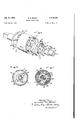
- Figure 1 is a fragmentary vertical sectional view through a rotary impact tool embodying my invention.
- Fig. 2 is a transverse sectional view taken approximately in the plane of line 2 2 of Fig. 1.
- Fig. 3 is a fragmentary horizontal sectional view taken approximately in the plane of line 3--3 of Fig. 1.
- Fig. 4 is a cross sectional view on line d-t of Fig. 1.
- Fig. 5 is an exploded view in perspective of certain of the elements of the clutch mechanism.
- Fig. 6 is a transverse sectional view in the plane of line 6 6 of Fig. 1.
- Fig. 7 is a similar view in the plane of line l-l of Fig. 3.
- I have herein shown for purposes of illustration an impact tool having a rotary air motor l@ y enclosed within the rear section Il of a tool casing having a forward section l2 enclosing a clutch mechanism generally designated I3.
- the two sections of .the casing are screw threaded together and the rear section is equipped with a handle I4 providing an air supply chamber I5 from which air is delivered to the motor under the control of a throttle valve I8.
- 'I'he motor I0 may be of any suitable or preferred construction. That herein shown is of the type disclosed in my prior Patent No. 2,099,280,
- the clutch mechanism comprises an anvil element 2
- the latter is equipped with a plurality of jaws 23 providing abrupt shoulders or faces 24 lying within substantially radial planes extending longitudinally of the axis of the tool.
- Complementary jaws 25 are formed on the hammer element in opposed relation to the anvil element and provide similarly disposed shoulders or faces 26 for coaction with the faces 24 of the Jaws 23.
- the hammer element is mounted upon a stub shaft 2l having a bearing in the anvil element 2
- engagement and disengagement of the hammer element with respect to the anvil element is accomplished by fluid pressure means operative to impart' intermittent pressure impulses to the hammer element 22 to produce a succession of blows on the anvil.
- fluid pressure operated means comprises a pressure chamber 29 having one wall or pressure area formed by the hammer element,
- valve device actuated automatically as an incident to the interruption in the rotation of the anvil element by the work being operated upon.
- the valve device has a part in the form of a disk 3
- the motor rotor I8 is formed with a forward axial extension 33 of hexagonal cross section (Fig. 2), which is received within a sleeve 34 forming part of a driver 35 and having a hexagonal socket 38 for receiving the rotor extension 33.
- the hammer element is generally in the form of a disk from the periphery of which the iiange 32 projects rearwardly so as to form the outer peripheral wall of the chamber 29. Within this ange is snugly fitted a ring 31 to the inner peripheral surface of which is bounded the outer peripheral edge of the diaphragm 30.
- the inner edge of the diaphragm in turn is bounded to the sleeve 34 so as to form the rear wall of the pressure chamber 29.
- Rigid with the sleeve A34 of the driver 35 is a hexagonal head 38 extending through a complementally shaped hole 39 in the valve disk 3
- the stub shaft 21 is preferably secured to the driver head 38 as by means of a pin 40.
- the motor rotor I8 has an axial passage 4
- the passage 4I extends through the rotor extension 33 and opens into a recess 44 in the driver head 38, said recess having radial ports 45 opening into the pressure chamber 29.
- fluid pressure is constantly admitted to the chamber 29.
- is splined upon the head 38 of the driver 35 so that in the operation of the rotor, the valve disk is positively driven. At the same time it is capable of moving axially with the hammer and with respect to the driver.
- the extent of relative rotation of the valve disk relative to the hammer is limited by means of a pair of pins 46 carried by the hammer element and projecting into radial slots 41 in the valve disk, the slots being of a width somewhat greater than the rliarneter of the pins so as to permit of a limited relative rotational movement between the valve disk and the hammer element.
- Such relative rotational movement is utilized to permit the exhaust of air from the chamber. For this purpose.
- the valve disk is provided in the present instance with a series of radial ports 48 coacting with another series of ports 49 in the ange 32 of the hammer element.
- a series of radial ports 48 coacting with another series of ports 49 in the ange 32 of the hammer element.
- the ports 48 are disposed between adjacent ports 49 and. depending upon the direction of rotation of the driver. when the hammer element is interrupted in its rotation by engagement with the anvil element, the ports 48 move into register with the ports 49.
- the pins 46 and their coacting notches 41 properly limit the extent of relative shifting movement of the two parts of the valve device.
- the hammer element In the rotation of the rotor, the hammer element is driven by the diaphragm 30 by reason of the bonded connection between the driver 35 and the hammer element. In such rotationy the hammer element occupies a position with respect to the valve disk 3
- valve device is effective to cause lntermittent pressure impulses to be transmitted to the hammer as an incident to the interruption of rotation of the hammer by the anvil.
- a rotary impact tool comprising, in combination, a fluid pressure operated motor, valve means controlling the supply of pressure iiuid to the motor, a rotary anvil, an axially shiftable hammer rotatable relative to the anvil, a driver for said hammer connected with said motor for rotation thereby, and means for effecting the engagement and disengagement of the by engagement with the anvil, said valve parts f being operative upon interruption of rotation of the hammer to permit the exhaust of pressure iluld from the pressure chamber.
- a clutch mechanism comprising, in combination, a rotary anvil, a hammer rotatable relative to the anvil and shiitable axially into and out of driving engagement with the anvil, a driver, and means for eiecting the engagement and disengagement of the hammer element with respect to the anvil comprising a diaphragm of resilient material connecting the driver with said hammer and coacting therewith to form a pressure chamber, an air supply passage, means for supplying air under pressure to said chamber during the rotation of the hammer by the driver, and valve means eifecting the exhaust of pressure uid from said chamber operative as an incident to the interruption of rotation of the hammer by the driver.
- a clutch mechanism comprising, in combination, a rotary anvil, a hammer rotatable relative to the anvil and shiftable axially into and out of driving engagement with the anvil, a driver, and means for eilecting the engagement and disengagement of the hammer element with respect to the anvill comprising a diaphragm of resilient material connecting the driver with said hammer and coacting therewith to form a pressure chamber, an air supply passage, means for supplying air under pressure to said chamber during the rotation of the hammer by the driver, and valve means effecting the exhaust of pressure iluid from said chamber operative as an incident to the interruption oi' rotation of the hammer by the driver, said valve means comprising a part associated with the hammer and a part connected with the driver for movement thereby relative to the hammer part.
- An impact clutch comprising, in combination, rotary anvil and hammer elements relatively shiftable into and out of driving engagement, means for driving the hammer element, and means for effecting the engagement and disengagement of said elements including a pressure chamber associated with one of said elements, means for admitting uid under pressure to said chamber to effect a relative shift of said elements into 'driving engagement, and a valve device operative to cause the intermittent exhaust of pressure uid from said chamber whereby to initiate a corresponding shift of said elements out of driving engagement.
- An impact clutch having, in combination, coaxial anvil and hammer elements mounted for relative axial shifting movement, means for driving the hammer element, means for effecting the intermittent engagement and disengagement of said elements including a pressure chamber having a resilient Wall providing a driving connection between the hammer element and said drive means, means for introducing pressure iluid into said chamber to effect a relative shift of said elementsin one direction, and means for intermittentiy exhausting the pressure fluid-'trom said cylment with the driver and coacting with the hammer element to form a pressure chamber, a rotatable anvil element, said hammer and anvil elements having coacting jaws and the two elements being relatively shiftable to eilect engagement and disengagement of said jaws, means for admitting iiuid under pressure to said chamber to efl'ect the engagement of said -jaws, and valve means operative upon interruption of rotation ci the hammer element by the anvil to permit escape of iluid pressure from said chamber and
- a rotary impact tool comprising, in combination, a rotary driver, a hammer, a diaphragm resiliently connecting the hammer with the driver and coacting with the hammer to form a pressure chamber, a rotatable anvil, said. hammer and anvil having coacting jaws and being relatively shiitable to eilect engagement and disengagement of said jaws.
- valve means for admitting fluid under pressure to said chamber to eiect the engagement of said jaws, and valve means operative upon interruption of rotation of the hammer by the anvil to permit escape of fluid pressure from said chamber and thereby eflect the disengagement of said jaws, said valve means comprising a part rotatable with the hammer and a part rotatable with the driver so as to be shiftable relative to the hammer part when rotation of the latter is interrupted.
- a rotary impact tool the combination oi a rotary anvil, a rotary hammer shiftable into and out of driving engagement with the anvil, a spring tending to hold the hammer out of engagement with the anvil, iluid pressure operated means for effecting the engagement of the hammer with the anvil, and valve means controlling 9.
- a rotary impact tool In a rotary impact tool, the combination of a rotary anvil, a rotary hammer shiftable into and out of driving engagement with the anvil, a spring tending to hold the hammer out of engagement with the anvil, and fluid pressure operated means for eflecting the engagement of the hammer with the anvil including a pressure chamber, and a valve device comprising a part actuated by the driver and rotatable relative to the hammer, a part carried by the hammer and means for limiting the extent oi' relative rotation between said valve parts.
- a rotary impact tool the combination of a rotary anvil, a rotary hammer shiftable into and out of driving engagement with the anvil, a spring tending to hold the hammer out of engagement with the anvil, fluid pressure operated means for effecting the engagement of the hammer with the anvil including a pressure chamber, and valve means operative to intermittently close and vent said chamber whereby to alternately increase and decrease the pressure in said chamber for shifting said hammer into and out of driving engagement with said anvil.
- An impact clutch comprising, in combination, rotary anvil and hammer elements relatively shiftable axially into and out of Adriving engagement, a driver, a resilient connection between the driver and the hammer element permitting of relative rotation of the hammer element with respect to the driver, said hammer 7 having a pressure area, and means for intermittently subjecting said area to fluid pressure whereby to cause movement of the hammer into engagement with the anvil.
- a rotary driver in combination, coaxial anvil and hammer elements mounted for relative axial shifting movement into and out of driving engagement, a rotary driver, a resilient member providing a. driving connection between said driver and said hammer element and defining one wall of a pressure chamber, means for introducing pressure fluid into said chamber to eecta relative axial shifting of said elements in a direction to establish a driving engagement therebetween, said member yielding in a circumferential direction to permit relative rotational movement of the hammer element and said driver when a predetermined resistance is opposed to the rotation of the anvil element, and valve means operative upon such relative rotation for venting said chamber to ellect a relative axial shifting of said elements in a direction to interrupt the driving engagement between the elements.
- anvil and hammer elements relatively shiftable axially into and out of driving engagement
- a rotary driver means operatively connecting said driver and said hammer element, pressure fluid actuated means operative to relatively shift said elements and maintain them in driving engagement
- said connecting means permitting limited rotational movement of said hammer element relative to said driver when a predetermined resistance is opposed to the rotation of said anvil element
- valve means operative incident to said relative rotation of said hammer element and said driver for rendering said pressure fluid actuated means ineffective to maintain said elements in driving engagement.
Landscapes
- Engineering & Computer Science (AREA)
- Mechanical Engineering (AREA)
- Percussive Tools And Related Accessories (AREA)
Description
July 19, 1949.
Filed May 20, 1947 Fig. i
E. H. SHAFF Flg- E 2 Sheets-Sheet l r'ncet CH- Shelf- PMMma/ july 19, 949 E, H, SHAFF Zg ROTARY IMPACT TOOL Filed May 20, 1947 2 Sheets-Sheet 2 uvam-row vv-"wrist CH. Shar; 3J 514, Pmfdm, a/vy,
Patented .Juiyn 19, 1949 ROTARY IMPACT TOOL Ernt H. Shaft, Spring Lake, Mich., assignor to Keller Tool Company, Grand Haven, Mich., a
corporation of Michigan Application May 20, 1947, Serial No. 749,280
14 Claims. (Cl. 192-.096)
The inventionrelates to rotary impact tools of the type intended for use as nut runners, impact wrenches and the like, and the general aim of the invention is to provide a rotary impact tool embodying a disengageable clutch mechanism characterized by extreme simplicity in construction, low cost of manufacture and eillciency in operation.
The invention concerns especially a rotary impact `tool utilizing an air motor, and the primary obj ect of the invention is to provide in such a tool, fluid pressure operated means for effecting engagement and disengagement if the clutch mechanism. 'f
A further object is to provide an impact clutch for tools of the character set forth having rotary anvil and hammer elements and embodying pressure uid actuated means and control means -therefor operative to impart rapidly recurring pressure impulses to the hammer element to effect the engagement and disengagement thereof with respect to the anvil element.
Another object is to provide in an impact clutch having a rotary anvil element, a motor driven hammer element movable into and out of driving engagement with the anvil element by pressure uid actuated means including a pressure chamber and valve means whereby fluid pressure is admitted to the chamber during the rotation of the hammer element and is exhausted from the chamber-upon interruption of rotation of the anvil element.
The objects of the invention thus generally set forth, together with other and ancillary advantages, are attained by the construction and arrangement shownby way of illustration in the accompanying drawings. in which:
Figure 1 is a fragmentary vertical sectional view through a rotary impact tool embodying my invention.
Fig. 2 is a transverse sectional view taken approximately in the plane of line 2 2 of Fig. 1.
Fig. 3 is a fragmentary horizontal sectional view taken approximately in the plane of line 3--3 of Fig. 1.
Fig. 4 is a cross sectional view on line d-t of Fig. 1. v
Fig. 5 is an exploded view in perspective of certain of the elements of the clutch mechanism.
Fig. 6 is a transverse sectional view in the plane of line 6 6 of Fig. 1.
Fig. 7 is a similar view in the plane of line l-l of Fig. 3.
I have herein shown for purposes of illustration an impact tool having a rotary air motor l@ y enclosed within the rear section Il of a tool casing having a forward section l2 enclosing a clutch mechanism generally designated I3. The two sections of .the casing are screw threaded together and the rear section is equipped with a handle I4 providing an air supply chamber I5 from which air is delivered to the motor under the control of a throttle valve I8.
'I'he motor I0 may be of any suitable or preferred construction. That herein shown is of the type disclosed in my prior Patent No. 2,099,280,
dated November 16, 1937. It consists in general of a cylinder I1 enclosing a rotor I8 with radial vanes or blades I9. A reversing valve 20 controls the direction of rotation of the motor. y
The clutch mechanism comprises an anvil element 2| mounted for rotation in the forward section I2 of the casing, and a hammer element 22 mounted for rotary and axial movement with respect to the anvil element. The latter is equipped with a plurality of jaws 23 providing abrupt shoulders or faces 24 lying within substantially radial planes extending longitudinally of the axis of the tool. Complementary jaws 25 are formed on the hammer element in opposed relation to the anvil element and provide similarly disposed shoulders or faces 26 for coaction with the faces 24 of the Jaws 23. The hammer element is mounted upon a stub shaft 2l having a bearing in the anvil element 2|, and a coiled compression spring 28 encircles the shaft in interposed relation to the anvil and hammer elements so as to tend to eilect a separation of the two elements.
In accordance with my invention, engagement and disengagement of the hammer element with respect to the anvil element is accomplished by fluid pressure means operative to impart' intermittent pressure impulses to the hammer element 22 to produce a succession of blows on the anvil. In the present preferred embodiment of the invention such uid pressure operated means comprises a pressure chamber 29 having one wall or pressure area formed by the hammer element,
and an opposed wall formed by a diaphragm Ell of flexible and resilient material such as rubber. To effect the engagement and disengagement of the hammer element from the anvil, fluid pressure is admitted to the chamber 29while the hammer is rotating and is periodically exhausted therefrom when the anvil and therefore the hammer are interrupted in their rotation. In the present instance pressure fluid is constantly delivered to the chamber and is exhausted therefrom under the control of a valve device actuated automatically as an incident to the interruption in the rotation of the anvil element by the work being operated upon. As shown. the valve device has a part in the form of a disk 3| driven by the motor, and a second part in the form of a circular flange 32 (Fig. 3) rigid with the hammer element, the arrangement being such that when the hammer element is interrupted in its rotation by engagement with the anvil, the parts of the valve device are relatively shifted so as to exhaust fluid pressure from the chamber.
Referring now more particularly to the construction and arrangement herein employed in providing the pressure chamber 29, the motor rotor I8 is formed with a forward axial extension 33 of hexagonal cross section (Fig. 2), which is received within a sleeve 34 forming part of a driver 35 and having a hexagonal socket 38 for receiving the rotor extension 33. The hammer element is generally in the form of a disk from the periphery of which the iiange 32 projects rearwardly so as to form the outer peripheral wall of the chamber 29. Within this ange is snugly fitted a ring 31 to the inner peripheral surface of which is bounded the outer peripheral edge of the diaphragm 30. The inner edge of the diaphragm in turn is bounded to the sleeve 34 so as to form the rear wall of the pressure chamber 29. Rigid with the sleeve A34 of the driver 35 is a hexagonal head 38 extending through a complementally shaped hole 39 in the valve disk 3| and into a circular recess 39a in the hammer element. The stub shaft 21 is preferably secured to the driver head 38 as by means of a pin 40.
To supply air under pressure to the chamber 29, the motor rotor I8 has an axial passage 4| communicating with a chamber 42 formed in the rear casing section II and supplied with air by way of a port 43 in either position of the reversing valve 20. The passage 4I extends through the rotor extension 33 and opens into a recess 44 in the driver head 38, said recess having radial ports 45 opening into the pressure chamber 29. Thus fluid pressure is constantly admitted to the chamber 29.
It will be seen that the valve disk 3| is splined upon the head 38 of the driver 35 so that in the operation of the rotor, the valve disk is positively driven. At the same time it is capable of moving axially with the hammer and with respect to the driver. However, the extent of relative rotation of the valve disk relative to the hammer is limited by means of a pair of pins 46 carried by the hammer element and projecting into radial slots 41 in the valve disk, the slots being of a width somewhat greater than the rliarneter of the pins so as to permit of a limited relative rotational movement between the valve disk and the hammer element. Such relative rotational movement is utilized to permit the exhaust of air from the chamber. For this purpose. the valve disk is provided in the present instance with a series of radial ports 48 coacting with another series of ports 49 in the ange 32 of the hammer element. As shown in Fig. 4, there are two sets of the ports 48 and 49. with three ports 48 in each set and four ports 49. In the normal relationship of the parts (Fig. 4). the ports 48 are disposed between adjacent ports 49 and. depending upon the direction of rotation of the driver. when the hammer element is interrupted in its rotation by engagement with the anvil element, the ports 48 move into register with the ports 49. In this connection, it will be '4 observed that the pins 46 and their coacting notches 41 properly limit the extent of relative shifting movement of the two parts of the valve device.
In the operation of the tool, fluid under pressure is constantly admitted to the pressure chamber 29 whenever the throttle valve I6 is operated to supply air to the motor. Thus, air flows from the chamber I5 past the valve I6 and reversing valve 28 into the chamber 42, and thence through the passage 4I to the recess 44 of the driver from which it passes to the chamber through the ports 45.
In the rotation of the rotor, the hammer element is driven by the diaphragm 30 by reason of the bonded connection between the driver 35 and the hammer element. In such rotationy the hammer element occupies a position with respect to the valve disk 3| shown in Fig. 4 so that the escape of fluid pressure from the chamber 29 is cut oi. The result is that the hammer element is slid axially flexing the diaphragm substantially as shown in Fig. 3, to carry the driving jaws 25 of the hammer element into engagement with the jaws 23 of the anvil element. This relationship of the parts continues during the nut running or equivalent operation, but when the anvil element is interrupted in its rotation, the hammer element is likewise interrupted, Whereupon the valve disk 3| continues its rotation with the driver, carrying the ports 48 into register with the ports 49 so as to vent the chamber 29 and permit the exhaust-of uid pressure from the chamber. The exhausting fluid pressure enters the forward housing section I 2 from which it passes rearwardly through one or more ports 48 in one of the end plates of the motor, and thence through radial ports 49, an annular recess 50 and one or more exhaust ports 5|.
Upon the exhaust of uid from the chamber 29, pressure within the chamber is quickly relieved to permit the diaphragm, assisted by the spring 28, to disengage the hammer element from the anvil element. In the relative rotational movement of the driver with respect to the hammer element incident to the interruption of the rotation of the latter, the diaphragm 30 yields in a circumferential direction, and because of the resiliency oi' this diaphragm. the parts are restored, upon disengagement of the hammer element from the anvil element. to normal relationship, thus closing the ports 49. Thus pressure fluid again builds up in the chamber 49, forcing the hammer element into engagement with the anvil element and the operation is repeated.
It will of course be understood that in the absence of valve means controlling the inlet ports 45, the outlet ports 48, 49 are proportioned with respect to the inlet ports as to permit of the escape of pressure iluid from the chamber much faster than it is supplied to the chamber. Thus the valve device is effective to cause lntermittent pressure impulses to be transmitted to the hammer as an incident to the interruption of rotation of the hammer by the anvil.
I claim as my invention:
1. A rotary impact tool comprising, in combination, a fluid pressure operated motor, valve means controlling the supply of pressure iiuid to the motor, a rotary anvil, an axially shiftable hammer rotatable relative to the anvil, a driver for said hammer connected with said motor for rotation thereby, and means for effecting the engagement and disengagement of the by engagement with the anvil, said valve parts f being operative upon interruption of rotation of the hammer to permit the exhaust of pressure iluld from the pressure chamber.
2. In a rotary impact tool, a clutch mechanism comprising, in combination, a rotary anvil, a hammer rotatable relative to the anvil and shiitable axially into and out of driving engagement with the anvil, a driver, and means for eiecting the engagement and disengagement of the hammer element with respect to the anvil comprising a diaphragm of resilient material connecting the driver with said hammer and coacting therewith to form a pressure chamber, an air supply passage, means for supplying air under pressure to said chamber during the rotation of the hammer by the driver, and valve means eifecting the exhaust of pressure uid from said chamber operative as an incident to the interruption of rotation of the hammer by the driver.
3. In a rotary impact tool, a clutch mechanism comprising, in combination, a rotary anvil, a hammer rotatable relative to the anvil and shiftable axially into and out of driving engagement with the anvil, a driver, and means for eilecting the engagement and disengagement of the hammer element with respect to the anvill comprising a diaphragm of resilient material connecting the driver with said hammer and coacting therewith to form a pressure chamber, an air supply passage, means for supplying air under pressure to said chamber during the rotation of the hammer by the driver, and valve means effecting the exhaust of pressure iluid from said chamber operative as an incident to the interruption oi' rotation of the hammer by the driver, said valve means comprising a part associated with the hammer and a part connected with the driver for movement thereby relative to the hammer part.
4. An impact clutch comprising, in combination, rotary anvil and hammer elements relatively shiftable into and out of driving engagement, means for driving the hammer element, and means for effecting the engagement and disengagement of said elements including a pressure chamber associated with one of said elements, means for admitting uid under pressure to said chamber to effect a relative shift of said elements into 'driving engagement, and a valve device operative to cause the intermittent exhaust of pressure uid from said chamber whereby to initiate a corresponding shift of said elements out of driving engagement.
5. An impact clutch having, in combination, coaxial anvil and hammer elements mounted for relative axial shifting movement, means for driving the hammer element, means for effecting the intermittent engagement and disengagement of said elements including a pressure chamber having a resilient Wall providing a driving connection between the hammer element and said drive means, means for introducing pressure iluid into said chamber to effect a relative shift of said elementsin one direction, and means for intermittentiy exhausting the pressure fluid-'trom said cylment with the driver and coacting with the hammer element to form a pressure chamber, a rotatable anvil element, said hammer and anvil elements having coacting jaws and the two elements being relatively shiftable to eilect engagement and disengagement of said jaws, means for admitting iiuid under pressure to said chamber to efl'ect the engagement of said -jaws, and valve means operative upon interruption of rotation ci the hammer element by the anvil to permit escape of iluid pressure from said chamber and thereby effect the disengagement of said jaws.
7. A rotary impact tool comprising, in combination, a rotary driver, a hammer, a diaphragm resiliently connecting the hammer with the driver and coacting with the hammer to form a pressure chamber, a rotatable anvil, said. hammer and anvil having coacting jaws and being relatively shiitable to eilect engagement and disengagement of said jaws. means for admitting fluid under pressure to said chamber to eiect the engagement of said jaws, and valve means operative upon interruption of rotation of the hammer by the anvil to permit escape of fluid pressure from said chamber and thereby eflect the disengagement of said jaws, said valve means comprising a part rotatable with the hammer and a part rotatable with the driver so as to be shiftable relative to the hammer part when rotation of the latter is interrupted.
8. In a rotary impact tool, the combination oi a rotary anvil, a rotary hammer shiftable into and out of driving engagement with the anvil, a spring tending to hold the hammer out of engagement with the anvil, iluid pressure operated means for effecting the engagement of the hammer with the anvil, and valve means controlling 9. In a rotary impact tool, the combination of a rotary anvil, a rotary hammer shiftable into and out of driving engagement with the anvil, a spring tending to hold the hammer out of engagement with the anvil, and fluid pressure operated means for eflecting the engagement of the hammer with the anvil including a pressure chamber, and a valve device comprising a part actuated by the driver and rotatable relative to the hammer, a part carried by the hammer and means for limiting the extent oi' relative rotation between said valve parts.
10. In a rotary impact tool, the combination of a rotary anvil, a rotary hammer shiftable into and out of driving engagement with the anvil, a spring tending to hold the hammer out of engagement with the anvil, fluid pressure operated means for effecting the engagement of the hammer with the anvil including a pressure chamber, and valve means operative to intermittently close and vent said chamber whereby to alternately increase and decrease the pressure in said chamber for shifting said hammer into and out of driving engagement with said anvil.
1l. An impact clutch comprising, in combination, rotary anvil and hammer elements relatively shiftable axially into and out of Adriving engagement, a driver, a resilient connection between the driver and the hammer element permitting of relative rotation of the hammer element with respect to the driver, said hammer 7 having a pressure area, and means for intermittently subjecting said area to fluid pressure whereby to cause movement of the hammer into engagement with the anvil.
12. In a rotary impact tool, in combination, coaxial anvil and hammer elements mounted for relative axial shifting movement into and out of driving engagement, a rotary driver, a resilient member providing a. driving connection between said driver and said hammer element and defining one wall of a pressure chamber, means for introducing pressure fluid into said chamber to eecta relative axial shifting of said elements in a direction to establish a driving engagement therebetween, said member yielding in a circumferential direction to permit relative rotational movement of the hammer element and said driver when a predetermined resistance is opposed to the rotation of the anvil element, and valve means operative upon such relative rotation for venting said chamber to ellect a relative axial shifting of said elements in a direction to interrupt the driving engagement between the elements.
13. In a tool of the class described, in combination, coaxially'arranged driving and driven elements supported for relative axial and rotational elements in one direction, said resilient member acting normally to hold said elements in predetermined angular relationship and yielding in a circumferential direction to permit relative rotation of the elements when a predetermined resistance is opposed to the rotation of said driven element, and means operative upon such relative rotation of the elements or venting said chamber to effect a relative axial movement of the elements in the opposite direction.
14. In a rotary impact tool, in combination, co-
axially arranged anvil and hammer elements relatively shiftable axially into and out of driving engagement, a rotary driver, means operatively connecting said driver and said hammer element, pressure fluid actuated means operative to relatively shift said elements and maintain them in driving engagement, said connecting means permitting limited rotational movement of said hammer element relative to said driver when a predetermined resistance is opposed to the rotation of said anvil element, and valve means operative incident to said relative rotation of said hammer element and said driver for rendering said pressure fluid actuated means ineffective to maintain said elements in driving engagement.
ERNEST H. SHAFF.
REFERENCES CITED The following references are of record in the ie of this patent:
UNITED STATES PATENTS Number Name Date 2,128,761 Thomas Aug. 30, 1938 2,158,303 Pott May 16, 1939 2,160,622 Olson et al May 30, 1939 2,196,589 Jimerson Apr. 9, 1940 2,219,883 Amtsberg- Oct. 29, 1940 2,220,711 Fitch Nov. 5, 1940
Priority Applications (1)
| Application Number | Priority Date | Filing Date | Title |
|---|---|---|---|
| US749280A US2476632A (en) | 1947-05-20 | 1947-05-20 | Rotary impact tool |
Applications Claiming Priority (1)
| Application Number | Priority Date | Filing Date | Title |
|---|---|---|---|
| US749280A US2476632A (en) | 1947-05-20 | 1947-05-20 | Rotary impact tool |
Publications (1)
| Publication Number | Publication Date |
|---|---|
| US2476632A true US2476632A (en) | 1949-07-19 |
Family
ID=25013075
Family Applications (1)
| Application Number | Title | Priority Date | Filing Date |
|---|---|---|---|
| US749280A Expired - Lifetime US2476632A (en) | 1947-05-20 | 1947-05-20 | Rotary impact tool |
Country Status (1)
| Country | Link |
|---|---|
| US (1) | US2476632A (en) |
Cited By (30)
| Publication number | Priority date | Publication date | Assignee | Title |
|---|---|---|---|---|
| US2691434A (en) * | 1949-10-11 | 1954-10-12 | Ingersoll Rand Co | Biasing mechanism for impact wrenches |
| US2693867A (en) * | 1949-10-01 | 1954-11-09 | Spencer B Maurer | Rotary impact tool |
| US2700443A (en) * | 1950-03-17 | 1955-01-25 | Reed Roller Bit Co | Torque clutch |
| US2725961A (en) * | 1951-12-11 | 1955-12-06 | Spencer B Maurer | Torque control for rotary impact tool |
| US2725918A (en) * | 1955-01-11 | 1955-12-06 | Ingersoll Rand Co | Tube rolling device |
| US2727598A (en) * | 1951-10-22 | 1955-12-20 | Thor Power Tool Co | Impact wrench torque control |
| US2730212A (en) * | 1952-01-08 | 1956-01-10 | Dillon Stevens | Releasable torque transmitting apparatus |
| US2733621A (en) * | 1956-02-07 | John p | ||
| US2740507A (en) * | 1952-12-24 | 1956-04-03 | Gardner Denver Co | Torque control means for power operated nut setters and the like |
| US2783628A (en) * | 1955-05-31 | 1957-03-05 | Blackstone & Co Ltd | Flexible couplings |
| US2784625A (en) * | 1952-03-25 | 1957-03-12 | Spencer B Maurer | Rotary impact tool |
| US2784818A (en) * | 1955-03-22 | 1957-03-12 | Gardner Denver Co | Impact tool with rotary position valve |
| DE1016153B (en) * | 1954-10-30 | 1957-09-19 | Duss Maschf | Electric hand grinder with fan wheel |
| US2821276A (en) * | 1954-02-10 | 1958-01-28 | Ingersoll Rand Co | Rotary impact tool |
| US2905149A (en) * | 1957-03-28 | 1959-09-22 | Gardner Denver Co | Rotary tool construction |
| US3015244A (en) * | 1956-04-19 | 1962-01-02 | John P Newman | Rotary impact hammer |
| US3104743A (en) * | 1963-09-24 | reynolds | ||
| US3107765A (en) * | 1960-02-11 | 1963-10-22 | Jered Ind Inc | Torque responsive clutch disconnect mechanism |
| US3181672A (en) * | 1961-06-20 | 1965-05-04 | Gardner Denver Co | Tension control wrench |
| US3182777A (en) * | 1963-04-15 | 1965-05-11 | Deere & Co | Torque-limiting drive |
| US3407885A (en) * | 1967-03-10 | 1968-10-29 | Reed International Inc | Air balance for impact wrenches |
| US3426856A (en) * | 1967-06-09 | 1969-02-11 | Hughes Tool Co | Control valve for limiting hydraulic motor speedup |
| US4098354A (en) * | 1976-06-04 | 1978-07-04 | Technical Research Corporation | Impact driver for electric drill |
| US20050109407A1 (en) * | 2003-11-24 | 2005-05-26 | Bass Gary S. | Valve |
| US20060096285A1 (en) * | 2004-11-10 | 2006-05-11 | Bass Gary S | Valve |
| EP3666465A1 (en) * | 2018-07-18 | 2020-06-17 | Milwaukee Electric Tool Corporation | Impulse driver |
| US20230048818A1 (en) * | 2019-10-29 | 2023-02-16 | Atlas Copco Industrial Technique Ab | Socket for a tightening tool |
| US11724368B2 (en) | 2020-09-28 | 2023-08-15 | Milwaukee Electric Tool Corporation | Impulse driver |
| US20230373067A1 (en) * | 2020-09-28 | 2023-11-23 | Milwaukee Electric Tool Corporation | Power tool with impulse assembly including a valve |
| US12208499B2 (en) | 2013-06-12 | 2025-01-28 | Makita Corporation | Impact power tool |
Citations (6)
| Publication number | Priority date | Publication date | Assignee | Title |
|---|---|---|---|---|
| US2128761A (en) * | 1937-07-03 | 1938-08-30 | Ingersoll Rand Co | Impact wrench |
| US2158303A (en) * | 1935-08-14 | 1939-05-16 | Robert H Pott | Impact tool |
| US2160622A (en) * | 1936-12-31 | 1939-05-30 | Chicago Pneumatic Tool Co | Nut runner |
| US2196589A (en) * | 1937-07-16 | 1940-04-09 | Ingersoll Rand Co | Impact tool |
| US2219883A (en) * | 1937-06-05 | 1940-10-29 | Chicago Pneumatic Tool Co | Impact wrench |
| US2220711A (en) * | 1936-01-07 | 1940-11-05 | Ingersoll Rand Co | Impact tool |
-
1947
- 1947-05-20 US US749280A patent/US2476632A/en not_active Expired - Lifetime
Patent Citations (6)
| Publication number | Priority date | Publication date | Assignee | Title |
|---|---|---|---|---|
| US2158303A (en) * | 1935-08-14 | 1939-05-16 | Robert H Pott | Impact tool |
| US2220711A (en) * | 1936-01-07 | 1940-11-05 | Ingersoll Rand Co | Impact tool |
| US2160622A (en) * | 1936-12-31 | 1939-05-30 | Chicago Pneumatic Tool Co | Nut runner |
| US2219883A (en) * | 1937-06-05 | 1940-10-29 | Chicago Pneumatic Tool Co | Impact wrench |
| US2128761A (en) * | 1937-07-03 | 1938-08-30 | Ingersoll Rand Co | Impact wrench |
| US2196589A (en) * | 1937-07-16 | 1940-04-09 | Ingersoll Rand Co | Impact tool |
Cited By (38)
| Publication number | Priority date | Publication date | Assignee | Title |
|---|---|---|---|---|
| US3104743A (en) * | 1963-09-24 | reynolds | ||
| US2733621A (en) * | 1956-02-07 | John p | ||
| US2693867A (en) * | 1949-10-01 | 1954-11-09 | Spencer B Maurer | Rotary impact tool |
| US2691434A (en) * | 1949-10-11 | 1954-10-12 | Ingersoll Rand Co | Biasing mechanism for impact wrenches |
| US2700443A (en) * | 1950-03-17 | 1955-01-25 | Reed Roller Bit Co | Torque clutch |
| US2727598A (en) * | 1951-10-22 | 1955-12-20 | Thor Power Tool Co | Impact wrench torque control |
| US2725961A (en) * | 1951-12-11 | 1955-12-06 | Spencer B Maurer | Torque control for rotary impact tool |
| US2730212A (en) * | 1952-01-08 | 1956-01-10 | Dillon Stevens | Releasable torque transmitting apparatus |
| US2784625A (en) * | 1952-03-25 | 1957-03-12 | Spencer B Maurer | Rotary impact tool |
| US2740507A (en) * | 1952-12-24 | 1956-04-03 | Gardner Denver Co | Torque control means for power operated nut setters and the like |
| US2821276A (en) * | 1954-02-10 | 1958-01-28 | Ingersoll Rand Co | Rotary impact tool |
| DE1016153B (en) * | 1954-10-30 | 1957-09-19 | Duss Maschf | Electric hand grinder with fan wheel |
| US2725918A (en) * | 1955-01-11 | 1955-12-06 | Ingersoll Rand Co | Tube rolling device |
| US2784818A (en) * | 1955-03-22 | 1957-03-12 | Gardner Denver Co | Impact tool with rotary position valve |
| US2783628A (en) * | 1955-05-31 | 1957-03-05 | Blackstone & Co Ltd | Flexible couplings |
| US3015244A (en) * | 1956-04-19 | 1962-01-02 | John P Newman | Rotary impact hammer |
| US2905149A (en) * | 1957-03-28 | 1959-09-22 | Gardner Denver Co | Rotary tool construction |
| US3107765A (en) * | 1960-02-11 | 1963-10-22 | Jered Ind Inc | Torque responsive clutch disconnect mechanism |
| US3181672A (en) * | 1961-06-20 | 1965-05-04 | Gardner Denver Co | Tension control wrench |
| US3182777A (en) * | 1963-04-15 | 1965-05-11 | Deere & Co | Torque-limiting drive |
| US3407885A (en) * | 1967-03-10 | 1968-10-29 | Reed International Inc | Air balance for impact wrenches |
| US3426856A (en) * | 1967-06-09 | 1969-02-11 | Hughes Tool Co | Control valve for limiting hydraulic motor speedup |
| US4098354A (en) * | 1976-06-04 | 1978-07-04 | Technical Research Corporation | Impact driver for electric drill |
| US8015997B2 (en) | 2003-11-24 | 2011-09-13 | Campbell Hausfeld/Scott Fetzer Company | Valve for a pneumatic hand tool |
| US7537027B2 (en) | 2003-11-24 | 2009-05-26 | Campbell Hausfeld/Scott Fetzer Company | Valve with duel outlet ports |
| US20050109407A1 (en) * | 2003-11-24 | 2005-05-26 | Bass Gary S. | Valve |
| US8430184B2 (en) | 2003-11-24 | 2013-04-30 | Campbell Hausfeld/Scott Fetzer Company | Valve for a pneumatic hand tool |
| US20060096285A1 (en) * | 2004-11-10 | 2006-05-11 | Bass Gary S | Valve |
| US7140179B2 (en) | 2004-11-10 | 2006-11-28 | Campbell Hausfeld/Scott Fetzer Company | Valve |
| US12208499B2 (en) | 2013-06-12 | 2025-01-28 | Makita Corporation | Impact power tool |
| US11213934B2 (en) | 2018-07-18 | 2022-01-04 | Milwaukee Electric Tool Corporation | Impulse driver |
| US11890726B2 (en) | 2018-07-18 | 2024-02-06 | Milwaukee Electric Tool Corporation | Impulse driver |
| EP3666465A1 (en) * | 2018-07-18 | 2020-06-17 | Milwaukee Electric Tool Corporation | Impulse driver |
| US20230048818A1 (en) * | 2019-10-29 | 2023-02-16 | Atlas Copco Industrial Technique Ab | Socket for a tightening tool |
| US12466038B2 (en) * | 2019-10-29 | 2025-11-11 | Atlas Copco Industrial Technique Ab | Socket for a tightening tool |
| US11724368B2 (en) | 2020-09-28 | 2023-08-15 | Milwaukee Electric Tool Corporation | Impulse driver |
| US20230373067A1 (en) * | 2020-09-28 | 2023-11-23 | Milwaukee Electric Tool Corporation | Power tool with impulse assembly including a valve |
| US12325112B2 (en) * | 2020-09-28 | 2025-06-10 | Milwaukee Electric Tool Corporation | Power tool with impulse assembly including a valve |
Similar Documents
| Publication | Publication Date | Title |
|---|---|---|
| US2476632A (en) | Rotary impact tool | |
| US3951217A (en) | Impact air wrench having a two position pressure regulator | |
| US5346024A (en) | Tool construction | |
| US2566183A (en) | Portable power-driven tool | |
| US4019589A (en) | Pulse motor nut runner | |
| US2261204A (en) | Governor for impact wrenches | |
| US3616864A (en) | Torque-controlled motor shutoff for power tool | |
| US3298481A (en) | Torque release and shut off device for rotary pneumatic tools | |
| SE440759B (en) | REVERSIBLE PRESSURE AIR TOOL | |
| US4140446A (en) | Rotary pneumatic tool with vibration absorbing means | |
| US3275047A (en) | Fastener holder for power tools | |
| US2821276A (en) | Rotary impact tool | |
| US2801718A (en) | Impact clutch mechanism | |
| US2159232A (en) | Pressure fluid motor | |
| US3082742A (en) | Torque tool control | |
| US2564224A (en) | Impact tool | |
| US2715889A (en) | Reversing pneumatic motor | |
| US2580607A (en) | Impact type clutch | |
| US2740507A (en) | Torque control means for power operated nut setters and the like | |
| US2143173A (en) | Rotary driving tool | |
| US2591323A (en) | Power-operated impact wrench | |
| US2285639A (en) | Impact clutch | |
| US3465646A (en) | Pneumatic motor structure | |
| US3072232A (en) | Rotary impact tool | |
| US2581033A (en) | Axially offset, motor operated, impact-type wrench |