US2655700A - Apparatus for handling and separating casting drum and casting - Google Patents
Apparatus for handling and separating casting drum and casting Download PDFInfo
- Publication number
- US2655700A US2655700A US203088A US20308850A US2655700A US 2655700 A US2655700 A US 2655700A US 203088 A US203088 A US 203088A US 20308850 A US20308850 A US 20308850A US 2655700 A US2655700 A US 2655700A
- Authority
- US
- United States
- Prior art keywords
- drum
- casting
- yoke
- handling
- cylinder
- Prior art date
- Legal status (The legal status is an assumption and is not a legal conclusion. Google has not performed a legal analysis and makes no representation as to the accuracy of the status listed.)
- Expired - Lifetime
Links
- 238000005266 casting Methods 0.000 title description 42
- 230000007246 mechanism Effects 0.000 description 6
- 239000002184 metal Substances 0.000 description 5
- 238000000034 method Methods 0.000 description 4
- 229910000978 Pb alloy Inorganic materials 0.000 description 2
- 229910000831 Steel Inorganic materials 0.000 description 2
- 230000006378 damage Effects 0.000 description 2
- 239000010959 steel Substances 0.000 description 2
- 238000010276 construction Methods 0.000 description 1
- 210000005069 ears Anatomy 0.000 description 1
- 239000012530 fluid Substances 0.000 description 1
- 230000000284 resting effect Effects 0.000 description 1
- 239000011435 rock Substances 0.000 description 1
- 238000005096 rolling process Methods 0.000 description 1
- 238000003466 welding Methods 0.000 description 1
Images


Classifications
-
- B—PERFORMING OPERATIONS; TRANSPORTING
- B22—CASTING; POWDER METALLURGY
- B22D—CASTING OF METALS; CASTING OF OTHER SUBSTANCES BY THE SAME PROCESSES OR DEVICES
- B22D29/00—Removing castings from moulds, not restricted to casting processes covered by a single main group; Removing cores; Handling ingots
Definitions
- the invention relates to mechanical apparatus for efficiently and safely handling a casting drum within which a backed electrographic shell is contained and for separating the backed shell and drum.
- the invention consists in the novel parts, constructions, arrangements, combinations and improvements herein shown and described.
- the apparatus of the invention is utilized in the process of forming curvedor arcuate printing plates which are secured to the plate cylinder of a rotary printing press, in which process a plastic or other suitable mold is formed and an electrotypers shell is deposited on the mold.
- the electrodeposited shell, separated from the mold, is assembled with other similarly produced arcuate shells in a hollow' cylinder or casting drum, and rotated at a relatively high rate of speed while molten metal such as lead alloy is poured in the drum to form a dense layer of backing metal for the assembled shells.
- the cast cylinder comprising the shells and backing layer are then removed from the drum and out along parallel, axial lines to provide a plurality of arouate parts which are finally finished as plates for affixing to the plate cylinder of the press.
- the apparatus of the present invention provides means in carrying out the above process for mechanically handling the casting drum containing the electrodeposited shells with metal backing layer, manipulating its position as desired and necessary for removing the cast cylinder from drum so that the cylinder maybe for-' warded for further operations and the drum retuned for subsequent casting.
- the casting drum and cylinder weigh as much as two or three hundred pounds or more, and the entire metal mass comprising the drum. and cylinder are quite hot from the casting operation since it is desired to separate them immediately in order to produce the finished plates with the minimum loss of time.
- the present invention accordingly provides an eflicient means for the necessary handling of the drum and cast cylinder under the circumstances mentioned, and the apparatus also prevents injuries to the exterior of the cast cylinder which is to become the printing surfaces in the finished plates, such injuries frequently arising where manual handling is involved with devices not specifically adapted for the purpose.
- the casting drum is moved across a table with its axis horizontal thereto and is received and temporarily held between pairs of upper and lower yoke arms.
- Means are provided for raising the yoke arms with the drum so positioned, and the yoke is rotatable about a horizontal axis with respect to its support so that the arms and supported drum may be rotated through to bring the axis of the drum perpendicular to the table.
- the table is provided with a cut out portion wherein is positioned a vertically movable lift having a head which is adapted to engage and support the cast cylinder composed of the shells and backing metal within the drum.
- Stationary supporting elements are provided to engage the casting drum but not to interfere with the cast cylinder within, so that the yoke with supported drum may be lowered to about table top level where the drum engages the stationary supports and the cylinder engages the head of the lift. The latter may then be lowered and the supported cylinder is withdrawn from the casting drum.
- the yoke is also rotatable about a vertical axis, so that it may now be again raised above the table top, the arms and drum rotated horizontally away from above the lift and cast cylinder, so that the lift may raise the cylinder to the level of the table top.
- the cylinder may then be moved safely across the table top toward further operations, and the yoke arms are rotated back to their beginning position with the axis of the casting drum horizontal to the table.
- the empty drum may now be removed fromthe yoke arms and returned across the table for a further casting operation.
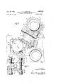
- Fig. 1 is a side elevation of thedevice of the invention with a casting drum shown in outline as it is about to enter the yoke arms, and in broken lines as it is received and supported by the arms;
- Fig. 2 is a cross sectional view of the device as shown in Fig. 1 taken along line 2-2 of Fig A
- Fig. 3 is a cross-sectional view taken along line 33 of Fig. 2 showing details of the yoke locking assembly;
- Fig. 4 is a fragmentary showing in side elevation corresponding to Fig. 1 but with the yoke arms and supported casting drum supported above the table;
- Fig. 5 is a fragmentary showing in side elevation of the yoke arms and supported drum after rotation so that the drum is vertically disposed above the table;
- Fig. 6 is a fragmentary view partly in side elevation and partly in cross section showing the mechanism after the drmn has been lowered to the table top from the position shown in Fig. 5 and the lift has been lowered beginning removal of the cylindrical casting.
- the stationary supporting elements for the casting drum are shown in broken lines displaced somewhat from their true position in order to clearly disclose their function;
- Fig. 7 is a top plan view of the mechanism at the time when the yoke and drum have been raised and horizontally rotated and the lift has raised the cast cylinder to table top level and the cylinder is being removed;
- Fig. 8 is a detail rear elevation of the yoke assembly as viewed from the supporting standard therefor.
- a stationary table top In (Fig. l) suitably supported by any suitable means (not shown).
- a casting drum Ii is rolled across the table top and received between a pair of upper yoke arms l2 and lower yoke arms l3, as shown in broken lines in Fig. l.
- the details of the casting drum and enclosed casting at this stage of the plate making process are best shown in Fig. 5 wherein the open ended drum i i is provided with annular end rings [4 removably held in place by set screws l5.
- the drum comprises the electrodeposited shell [6 and the backing layer I!
- Tires [8 comprising steel rings are secured to the exterior of the steel casting drum for easily rolling the drum about and for use in rotating the drum during casting.
- the yoke assembly comprises a, carrier plate 20 (Figs. 1, 2 and 8) to which are secured as by welding the two arms 2
- are suitably bored at various places as indicated by numeral 23, and tapered pins 24 enter the cooperating bores to hold the elbows at adjusted positions on the arms, thus enabling the spacement of the yoke arms l2 and I3 to be varied for handling drums ll of different diameters.
- ] is fast to a hollow cylindrical shaft 25 which is rotatably journalled in the journal 26 of the main yoke support or elbow 21, by means of bushing 28.
- Yoke support 21 is slidably mounted on vertical shaft 30, which is firmly grounded on the floor of the building and supports the entire yoke assembly for manipulating the casting drum.
- Yoke support 21 is vertically positionable along vertical shaft 30 by an eccentric extension collar 3
- Cylinder 34 is provided with appropriate fluid lines 35, and it will be apparent that the hydraulic cylinder furnishes the power for raising or lowering yoke support 21 along vertical shaft 30, together with the entire yoke arm assembly.
- a bracing member 38 may be provided for shaft 30.
- the yoke arms l2 and I3 may be rotated about the horizontal axis of shaft in handling a drum H, and they may also be rotated about the vertical axis of shaft to displace them with respect to table top "I.
- Locking means are provided for holding the assembly against this latter rotation and maintaining the yoke arms above the aperture 40 in the table top H).
- Such means comprise a lock bar ll (Figs. 2 and 3) positioned in axial grooves 42 and 43 of shaft 30 and yoke support 21 respectively.
- Said lock bar is spring pressed by coiled spring 44 toward shaft 30 where it occupies both grooves and prevents relative rotation, and may be retracted wholly into groove 48 to permit rotation, by arms 45 carried by shafts 46 which are pivotally mounted on ears 4! of yoke support 21
- a handle 48 permits easy operation of the locking mechanism.
- Means are provided for engaging and releasably holding a drum ll between yoke arms l2 and I8, and as embodied comprise a finger 5
- Such means are mounted on the lower yoke arms l3, and comprise a lock bar 52 slidably held with respect to each such arm and spring pressed by coiled spring 5! toward locking engagement in notch 54 of a finger 50.
- the bar is automatically retracted out of engagement when the lower yoke arms are adjacent table top 10 where it is desired to receive and discharge drums, by means of upstanding stationary cam fingers 55 which engage extensions 56 on each lock bar 52.
- Fig. 1 illustrates the described finger locking arrangement in lowered, unlocked position
- Fig. 4 shows the locked position upon hydraulically lifting the yoke arm assembly.
- the yoke arms l2, ii are arranged to lie closely ad acent tires 18 on the drum to prevent the latter from slipping out when it is vertically positioned, and the yoke arms and tires are coordinated so that single length or double length drums may be handled.
- ! actuating piston rod 8i carrying a lift head member 62 adapted to be projected into aperture 40 in table In and lowered therefrom.
- the head 82 is of a size to engage and support end ring I4, and is closely guided in its vertical movements by guide rods 63 passing through radial extensions 54 of the head.
- the drum I l is supported at table top level during lowering of head 62 and removal of the casting, upon rollers which are firmly supported on posts 65.
- the rollers 65 are provided so that the drum may be conveniently rotated by hand when resting thereon for loosening of set screws 15 of the lower end ring it preparatory to removing the casting.
- Casting drum II is rolled across table top H] between yoke arms l2-I3 (Fig. 1).
- the yoke arms are lifted and fingers 50 are automatically locked in place (Fig. 4).
- the yoke arm assembly is rotated to bring the drum into a vertical position, and the drum is lowered to rest upon rollers 65 (Fig. 5).
- the set screws 15 are loosened, and lift head 62 lowered to remove casting I6l7 (Fig. 6).
- the yoke assembly and drum are then raised again, pivoted out of the way (Fig. 7), lift head 62 is raised so that casting l6l
- Handling apparatus for a cylindrical casting drum and a member cast therein comprising a fiat horizontal support for receiving said drum in a horizontal position, said support being provided with an opening of sufficient size to receive the drum when it is in a vertical position, means for moving the drum.
- said means including a vertically movable support positioned for vertically moving the drum above and into said opening, spaced elements for receiving and holding the drum therebetween by engagement with the cylindrical wall of the drum and mounting means connecting said spaced elements and said vertically movable support, said mounting means including means for rotating said drum from a horizontal position to a vertical position and means for rotating said drum about the vertically movable support, a support at said opening for supporting the drum when in a vertical position, and a vertically movable lift positioned beneath the opening in the fiat support for receiving and lowering the cast member from the vertical drum.
- a handling apparatus as defined in claim 1, wherein the support at said opening comprises rollers which are positioned beneath the surface of the flat horizontal support.
Landscapes
- Engineering & Computer Science (AREA)
- Mechanical Engineering (AREA)
- Moulds For Moulding Plastics Or The Like (AREA)
Description
H. J. SNELSON APPARATUS FOR HANDLING AND SEPARATING CASTING DRUM AND CASTING Oct. 20, 1953 4 Sheets-Sheet 1 Filed Dec. 28, 1950 INVENTOR.
BY %W 444 Y A TTORNEKS.
Oct. 20, 1953 H. J. SNELSON 2,655,700
APPARATUS FOR HANDLING AND SEPARATING CASTING DRUM AND CASTING INVENTOR. How/2R0 J 5/VEL50N A TTO/FNEYS.
Oct. 20, 1953 H. J. SNELSON APPARATUS FOR HANDLING AND SEPARATING CASTING DRUM AND CASTING Filed Dec. 28, 1950 4 Sheets-Sheet 3 Jfiyfi l Z4 l I 22 z I 30 24k?) 47 /Z5 4 r 4a 1;; 4b 2/ mm I! A U 32 ...l T- l /07 N55 7 as V D i 5/ g g 20 J 2/ l8 22 1 24 Wm M T 66 1A LJ f; JNVENTOR.
Hon/mm J SNELJ N M BY M 1 M w; 43 ATTORNEYS.
J. SNELSON APPARATUS FOR HANDLING AND SEPARATING CASTING DRUM AND CASTING Oct. 20, 1953 4 Sheets-Sheet 4 Filed Dec. 28, 1950 INVENTOR. How/2R0 J SNELSON BY 77 4 7 6RNEY5.
4 A. a ww 2 ll H m k la Patented Oct. 20, 1953 APPARATUS FOR HANDLING AND SEPARAT- ING CASTING DRUM AND CASTING Howard J. Snelson, Paris, 111., assignor to Electrographic Corporation, New York, N. Y., a corporation of Delaware Application December 28, 1950, Serial No. 203,088
4 Claims.
The invention relates to mechanical apparatus for efficiently and safely handling a casting drum within which a backed electrographic shell is contained and for separating the backed shell and drum.
Objects and advantages of the invention will be set forth in part hereinafter and in part will be obvious herefrom, or may be learned by practice with the invention, the same being realized and attained by means of the instrumentalities and combinations pointed out in the appended claims.
The invention consists in the novel parts, constructions, arrangements, combinations and improvements herein shown and described.
The accompanying drawings, referred to herein and constituting a part hereof, illustrate an embodiment of the invention, and together with the description, serve to explain the principles of the invention.
The apparatus of the invention is utilized in the process of forming curvedor arcuate printing plates which are secured to the plate cylinder of a rotary printing press, in which process a plastic or other suitable mold is formed and an electrotypers shell is deposited on the mold. The electrodeposited shell, separated from the mold, is assembled with other similarly produced arcuate shells in a hollow' cylinder or casting drum, and rotated at a relatively high rate of speed while molten metal such as lead alloy is poured in the drum to form a dense layer of backing metal for the assembled shells. The cast cylinder comprising the shells and backing layer are then removed from the drum and out along parallel, axial lines to provide a plurality of arouate parts which are finally finished as plates for affixing to the plate cylinder of the press.
The apparatus of the present invention provides means in carrying out the above process for mechanically handling the casting drum containing the electrodeposited shells with metal backing layer, manipulating its position as desired and necessary for removing the cast cylinder from drum so that the cylinder maybe for-' warded for further operations and the drum retuned for subsequent casting. I The casting drum and cylinder weigh as much as two or three hundred pounds or more, and the entire metal mass comprising the drum. and cylinder are quite hot from the casting operation since it is desired to separate them immediately in order to produce the finished plates with the minimum loss of time. The present invention accordingly provides an eflicient means for the necessary handling of the drum and cast cylinder under the circumstances mentioned, and the apparatus also prevents injuries to the exterior of the cast cylinder which is to become the printing surfaces in the finished plates, such injuries frequently arising where manual handling is involved with devices not specifically adapted for the purpose.
With the apparatus of the invention the casting drum is moved across a table with its axis horizontal thereto and is received and temporarily held between pairs of upper and lower yoke arms. Means are provided for raising the yoke arms with the drum so positioned, and the yoke is rotatable about a horizontal axis with respect to its support so that the arms and supported drum may be rotated through to bring the axis of the drum perpendicular to the table. The table is provided with a cut out portion wherein is positioned a vertically movable lift having a head which is adapted to engage and support the cast cylinder composed of the shells and backing metal within the drum. Stationary supporting elements are provided to engage the casting drum but not to interfere with the cast cylinder within, so that the yoke with supported drum may be lowered to about table top level where the drum engages the stationary supports and the cylinder engages the head of the lift. The latter may then be lowered and the supported cylinder is withdrawn from the casting drum. The yoke is also rotatable about a vertical axis, so that it may now be again raised above the table top, the arms and drum rotated horizontally away from above the lift and cast cylinder, so that the lift may raise the cylinder to the level of the table top. The cylinder may then be moved safely across the table top toward further operations, and the yoke arms are rotated back to their beginning position with the axis of the casting drum horizontal to the table. The empty drum may now be removed fromthe yoke arms and returned across the table for a further casting operation.
, Of the drawings:
Fig. 1 is a side elevation of thedevice of the invention with a casting drum shown in outline as it is about to enter the yoke arms, and in broken lines as it is received and supported by the arms;
Fig. 2 is a cross sectional view of the device as shown in Fig. 1 taken along line 2-2 of Fig A Fig. 3 is a cross-sectional view taken along line 33 of Fig. 2 showing details of the yoke locking assembly;
Fig. 4 is a fragmentary showing in side elevation corresponding to Fig. 1 but with the yoke arms and supported casting drum supported above the table;
Fig. 5 is a fragmentary showing in side elevation of the yoke arms and supported drum after rotation so that the drum is vertically disposed above the table;
Fig. 6 is a fragmentary view partly in side elevation and partly in cross section showing the mechanism after the drmn has been lowered to the table top from the position shown in Fig. 5 and the lift has been lowered beginning removal of the cylindrical casting. In this figure the stationary supporting elements for the casting drum are shown in broken lines displaced somewhat from their true position in order to clearly disclose their function;
Fig. 7 is a top plan view of the mechanism at the time when the yoke and drum have been raised and horizontally rotated and the lift has raised the cast cylinder to table top level and the cylinder is being removed; and,
Fig. 8 is a detail rear elevation of the yoke assembly as viewed from the supporting standard therefor.
Referring now in detail to the illustrative embodiment of the invention shown by way of example in the accompanying drawings, there is provided a stationary table top In (Fig. l) suitably supported by any suitable means (not shown). A casting drum Ii is rolled across the table top and received between a pair of upper yoke arms l2 and lower yoke arms l3, as shown in broken lines in Fig. l. The details of the casting drum and enclosed casting at this stage of the plate making process are best shown in Fig. 5 wherein the open ended drum i i is provided with annular end rings [4 removably held in place by set screws l5. the drum comprises the electrodeposited shell [6 and the backing layer I! of lead alloy or the like which has just been cast in the drum, the shell and cast backing being held in place by the end rings ll. Tires [8 comprising steel rings are secured to the exterior of the steel casting drum for easily rolling the drum about and for use in rotating the drum during casting.
The yoke assembly comprises a, carrier plate 20 (Figs. 1, 2 and 8) to which are secured as by welding the two arms 2|, and at each end of each arm there is positioned an elbow 22 which individually support the yoke arms i2 and I3. The elbows 22 and arms 2| are suitably bored at various places as indicated by numeral 23, and tapered pins 24 enter the cooperating bores to hold the elbows at adjusted positions on the arms, thus enabling the spacement of the yoke arms l2 and I3 to be varied for handling drums ll of different diameters.
Continuing with the structure and support of the yoke mechanism, the plate 2|] is fast to a hollow cylindrical shaft 25 which is rotatably journalled in the journal 26 of the main yoke support or elbow 21, by means of bushing 28. Yoke support 21 is slidably mounted on vertical shaft 30, which is firmly grounded on the floor of the building and supports the entire yoke assembly for manipulating the casting drum. Yoke support 21 is vertically positionable along vertical shaft 30 by an eccentric extension collar 3| which is also slidably mounted on shaft 30 beneath yoke 21 but prevented from rotating on the shaft by a key 3|. Bearing against the underside of the eccentric extension of collar 3| is the head 32 of The cylindrical casting within g the piston rod 33 of a hydraulic double acting cylinder 34. Cylinder 34 is provided with appropriate fluid lines 35, and it will be apparent that the hydraulic cylinder furnishes the power for raising or lowering yoke support 21 along vertical shaft 30, together with the entire yoke arm assembly. A bracing member 38 may be provided for shaft 30.
The yoke arms l2 and I3 may be rotated about the horizontal axis of shaft in handling a drum H, and they may also be rotated about the vertical axis of shaft to displace them with respect to table top "I. Locking means are provided for holding the assembly against this latter rotation and maintaining the yoke arms above the aperture 40 in the table top H). Such means comprise a lock bar ll (Figs. 2 and 3) positioned in axial grooves 42 and 43 of shaft 30 and yoke support 21 respectively. Said lock bar is spring pressed by coiled spring 44 toward shaft 30 where it occupies both grooves and prevents relative rotation, and may be retracted wholly into groove 48 to permit rotation, by arms 45 carried by shafts 46 which are pivotally mounted on ears 4! of yoke support 21 A handle 48 permits easy operation of the locking mechanism.
Means are provided for engaging and releasably holding a drum ll between yoke arms l2 and I8, and as embodied comprise a finger 5|! pivotally mounted on each yoke arm and contoured to engage a cylindrical object. Said fingers are free to rock open to receive a drum H as shown in Fig. .1, and are prevented from continued pivotal movement to release the drum by means of stops 5i on each yoke arm l2 and I3. Locking means for the lower pair of fingers 50 are provided coming into operation automatically when the yoke assembly is lifted away from table top ll, preventing a drum from moving outwardly of the yoke arms. Such means are mounted on the lower yoke arms l3, and comprise a lock bar 52 slidably held with respect to each such arm and spring pressed by coiled spring 5! toward locking engagement in notch 54 of a finger 50. The bar is automatically retracted out of engagement when the lower yoke arms are adjacent table top 10 where it is desired to receive and discharge drums, by means of upstanding stationary cam fingers 55 which engage extensions 56 on each lock bar 52. Fig. 1 illustrates the described finger locking arrangement in lowered, unlocked position, and Fig. 4 shows the locked position upon hydraulically lifting the yoke arm assembly. The yoke arms l2, ii are arranged to lie closely ad acent tires 18 on the drum to prevent the latter from slipping out when it is vertically positioned, and the yoke arms and tires are coordinated so that single length or double length drums may be handled.
Turning now to a description of the mechamsm for handling and removing the casting l6ll from the drum II, there is provided a Second double acting hydraulic cylinder 6|! actuating piston rod 8i, the latter carrying a lift head member 62 adapted to be projected into aperture 40 in table In and lowered therefrom. As clearly shown in Figs. 5 and 6. the head 82 is of a size to engage and support end ring I4, and is closely guided in its vertical movements by guide rods 63 passing through radial extensions 54 of the head. The drum I l is supported at table top level during lowering of head 62 and removal of the casting, upon rollers which are firmly supported on posts 65. The rollers 65 are provided so that the drum may be conveniently rotated by hand when resting thereon for loosening of set screws 15 of the lower end ring it preparatory to removing the casting.
With the foregoing description it is thought the operation of the mechanism will be entirely clear. Casting drum II is rolled across table top H] between yoke arms l2-I3 (Fig. 1). The yoke arms are lifted and fingers 50 are automatically locked in place (Fig. 4). The yoke arm assembly is rotated to bring the drum into a vertical position, and the drum is lowered to rest upon rollers 65 (Fig. 5). The set screws 15 are loosened, and lift head 62 lowered to remove casting I6l7 (Fig. 6). The yoke assembly and drum are then raised again, pivoted out of the way (Fig. 7), lift head 62 is raised so that casting l6l| may be removed on table top 10 and forwarded, as along an inclined table 10 to further operations, such as the saw for separating the casting into individual printing plates.
The invention in its broader aspects is not limited to the specific mechanisms shown and described but departures may be made therefrom, within the scope of the accompanying claims, without departing from the principles of the invention and without sacrificing its chief advantages.
What is claimed is:
1. Handling apparatus for a cylindrical casting drum and a member cast therein comprising a fiat horizontal support for receiving said drum in a horizontal position, said support being provided with an opening of sufficient size to receive the drum when it is in a vertical position, means for moving the drum. in three ways, said means including a vertically movable support positioned for vertically moving the drum above and into said opening, spaced elements for receiving and holding the drum therebetween by engagement with the cylindrical wall of the drum and mounting means connecting said spaced elements and said vertically movable support, said mounting means including means for rotating said drum from a horizontal position to a vertical position and means for rotating said drum about the vertically movable support, a support at said opening for supporting the drum when in a vertical position, and a vertically movable lift positioned beneath the opening in the fiat support for receiving and lowering the cast member from the vertical drum.
2. A handling apparatus as defined in claim 1, wherein the support at said opening comprises rollers which are positioned beneath the surface of the flat horizontal support.
3. A handling apparatus as defined in claim 1, wherein said vertically movable supports are moved by hydraulic power.
4. A handling apparatus as defined in claim 1, wherein certain of said spaced elements have drum gripping fingers pivotally mounted thereon, and automatic locking means are provided, locking said gripping fingers against pivotal movement when said means for moving the drum is at a higher position and unlocking said gripping fingers when said means for moving the drum is at a lower position.
HOWARD J. SNELSON.
References Cited in the file of this patent UNITED STATES PATENTS Number Name Date 954,430 Griffith Apr. 12, 1910 1,377,978 Weber May 10, 1921 1,714,781 Henderson May 28, 1929 1,754,106 Hurst et al. Apr. 8, 1930 1,830,427 De Villers Nov. 3, 1931 1,942,919 Eurich et al. Jan. 9, 1934 2,112,830 Corbin Apr. 5, 1938 2,287,469 Cochran June 23, 1942 FOREIGN PATENTS Number Country Date 16,904 Great Britain 1896
Priority Applications (1)
| Application Number | Priority Date | Filing Date | Title |
|---|---|---|---|
| US203088A US2655700A (en) | 1950-12-28 | 1950-12-28 | Apparatus for handling and separating casting drum and casting |
Applications Claiming Priority (1)
| Application Number | Priority Date | Filing Date | Title |
|---|---|---|---|
| US203088A US2655700A (en) | 1950-12-28 | 1950-12-28 | Apparatus for handling and separating casting drum and casting |
Publications (1)
| Publication Number | Publication Date |
|---|---|
| US2655700A true US2655700A (en) | 1953-10-20 |
Family
ID=22752454
Family Applications (1)
| Application Number | Title | Priority Date | Filing Date |
|---|---|---|---|
| US203088A Expired - Lifetime US2655700A (en) | 1950-12-28 | 1950-12-28 | Apparatus for handling and separating casting drum and casting |
Country Status (1)
| Country | Link |
|---|---|
| US (1) | US2655700A (en) |
Cited By (2)
| Publication number | Priority date | Publication date | Assignee | Title |
|---|---|---|---|---|
| US2799905A (en) * | 1954-10-22 | 1957-07-23 | Price Battery Corp | Machine for casting straps and posts onto groups of insulated battery plates |
| US3062388A (en) * | 1960-03-16 | 1962-11-06 | Pettibone Mulliken Corp | Rotary flask and mold transfer and upending mechanism |
Citations (9)
| Publication number | Priority date | Publication date | Assignee | Title |
|---|---|---|---|---|
| GB189616904A (en) * | 1896-07-30 | 1897-06-05 | Moor Steel And Iron Company Lt | Improvements in Stripping Ingots from their Moulds. |
| US954430A (en) * | 1907-11-13 | 1910-04-12 | John Crist | Molding apparatus. |
| US1377978A (en) * | 1919-05-08 | 1921-05-10 | Otto L E Weber | Truck |
| US1714781A (en) * | 1926-08-24 | 1929-05-28 | H C Macaulay Foundry Company | Molding machine |
| US1754106A (en) * | 1928-01-17 | 1930-04-08 | Centrifugal Castings Ltd | Apparatus for extracting pipes and like cylindrical articles from the molds in which they are cast |
| US1830427A (en) * | 1927-05-19 | 1931-11-03 | Expansion Tech Soc D | Plant for the manufacture by centrifugation of pipes of any nature, and particularly of metal pipes |
| US1942919A (en) * | 1930-05-07 | 1934-01-09 | Youngstown Sheet And Tube Co | Machine for continuous centrifugal casting |
| US2112830A (en) * | 1938-04-05 | Molding machine | ||
| US2281469A (en) * | 1940-02-21 | 1942-04-28 | Meyers | Dado, gain, and miter saw |
-
1950
- 1950-12-28 US US203088A patent/US2655700A/en not_active Expired - Lifetime
Patent Citations (9)
| Publication number | Priority date | Publication date | Assignee | Title |
|---|---|---|---|---|
| US2112830A (en) * | 1938-04-05 | Molding machine | ||
| GB189616904A (en) * | 1896-07-30 | 1897-06-05 | Moor Steel And Iron Company Lt | Improvements in Stripping Ingots from their Moulds. |
| US954430A (en) * | 1907-11-13 | 1910-04-12 | John Crist | Molding apparatus. |
| US1377978A (en) * | 1919-05-08 | 1921-05-10 | Otto L E Weber | Truck |
| US1714781A (en) * | 1926-08-24 | 1929-05-28 | H C Macaulay Foundry Company | Molding machine |
| US1830427A (en) * | 1927-05-19 | 1931-11-03 | Expansion Tech Soc D | Plant for the manufacture by centrifugation of pipes of any nature, and particularly of metal pipes |
| US1754106A (en) * | 1928-01-17 | 1930-04-08 | Centrifugal Castings Ltd | Apparatus for extracting pipes and like cylindrical articles from the molds in which they are cast |
| US1942919A (en) * | 1930-05-07 | 1934-01-09 | Youngstown Sheet And Tube Co | Machine for continuous centrifugal casting |
| US2281469A (en) * | 1940-02-21 | 1942-04-28 | Meyers | Dado, gain, and miter saw |
Cited By (2)
| Publication number | Priority date | Publication date | Assignee | Title |
|---|---|---|---|---|
| US2799905A (en) * | 1954-10-22 | 1957-07-23 | Price Battery Corp | Machine for casting straps and posts onto groups of insulated battery plates |
| US3062388A (en) * | 1960-03-16 | 1962-11-06 | Pettibone Mulliken Corp | Rotary flask and mold transfer and upending mechanism |
Similar Documents
| Publication | Publication Date | Title |
|---|---|---|
| US4463794A (en) | Apparatus for producing containerless sand molds | |
| US2772838A (en) | Mechanism for extracting the rewind shaft from a core of a rewound roll and inserting this shaft into the core of a roll to be rewound | |
| US2655700A (en) | Apparatus for handling and separating casting drum and casting | |
| US4649631A (en) | Device for enabling the changeover of a roller shell or casing | |
| US3425256A (en) | Methods of and apparatus for manipulating rolls of multiple roll apparatus | |
| JPS599338B2 (en) | Tire material feeding device for tire press | |
| EP0289469A2 (en) | Machine for vulcanizing tires with devices for collecting and unloading the tire being treated | |
| US2745339A (en) | Apparatus for decorating concave and convex surfaces | |
| US2340262A (en) | Casting machine | |
| US2879545A (en) | Apparatus for separating and clamping mold sections in rotational casting machines | |
| US2365930A (en) | Apparatus for handling shells and similar objects | |
| US3564898A (en) | Shrink-forming apparatus with integral tooling | |
| US1758883A (en) | Apparatus for freeing and extracting castings from molds | |
| US3309765A (en) | Apparatus and methods for replacing the knife units of a woodcutting machine | |
| US3139024A (en) | Coil handling apparatus | |
| US2361906A (en) | Centrifugal apparatus | |
| US2353339A (en) | Centrifugal casting machine | |
| CS218561B2 (en) | Facility for manipulation with the nose cores fixed in the nose end of the permanent mould | |
| US3833049A (en) | Method for automatically stripping a sectionalized mold from a cast | |
| GB1495718A (en) | Slip casting apparatus | |
| CN213052706U (en) | Hub casting head removing tool | |
| US3102310A (en) | Spinning table assembly | |
| US4129171A (en) | Installation for handling socket cores for a centrifugal casting machine | |
| SU722670A1 (en) | Apparatus for removing casting from iron mold | |
| US3413919A (en) | Method and means for supporting the backing cylinder of printing apparatus to facilitate replacing an endless member extending partly around it |