US3144052A - Filling manipulating device - Google Patents
Filling manipulating device Download PDFInfo
- Publication number
- US3144052A US3144052A US92352A US9235261A US3144052A US 3144052 A US3144052 A US 3144052A US 92352 A US92352 A US 92352A US 9235261 A US9235261 A US 9235261A US 3144052 A US3144052 A US 3144052A
- Authority
- US
- United States
- Prior art keywords
- shuttle
- yarn
- cop
- hook
- filling
- Prior art date
- Legal status (The legal status is an assumption and is not a legal conclusion. Google has not performed a legal analysis and makes no representation as to the accuracy of the status listed.)
- Expired - Lifetime
Links
Images

Classifications
-
- D—TEXTILES; PAPER
- D03—WEAVING
- D03D—WOVEN FABRICS; METHODS OF WEAVING; LOOMS
- D03D45/00—Looms with automatic weft replenishment
- D03D45/50—Cutting, holding, manipulating, or disposing of, weft ends
Definitions
- This invention relates to tilling manipulating devices and more especially to improved means for replenishing the filling supply of a shuttle and delivering filling from same.
- the invention will be illustrated in connection with a carpet loom and shuttle for which the invention is particularly adapted for use.
- the loom illustrated includes Aa cop changer of the type illustrated in United States Letters Patent No. 2,871,889 known as the Egelhaaf Cop Changer.
- the lling replenishing operation is especially important because the yarn is of a coarse type generally supplied in the form of a cop which becomes exhausted after about a 90 second run.
- a hook is lowered toward the shuttle when the cop changing operation commences. As the shuttle moves beneath the hook, the hook passes longitudinally through the longitudinal yarn delivery channel into the cop storing cavity to engage and remove the butt of the cop to be discharged.
- One diiiiculty with removing the butt of the cop is that it is diiiicult to insure positive removal of the yarn forming the last pick from the delivery means of the shuttle.
- An important object of this invention is the provision of a shuttle having automatic means for severing the yarn from the iinal pick from the shuttle upon a supply changing operation.
- Another object of the invention is the provision of a cop shuttle providing adjustable tension means for maintaining desired tension upon the yarn delivered therefrom ⁇ g p
- Another object of the invention is to provide tensioning means for a cop shuttle which will not interfere with the operation of removing the butt of the exhausted cop.
- Still another object of the invention is to provide a positive means for severing the last filling from a cop shuttle without interfering with the cop changing opera- Ition.
- Yet another object of the invention is to provide a loom 3,144,052 Patented Aug. l1, 1964 ice having means coacting with the shuttle for actuating means carried by the shuttle for severing the pick yarn therefrom preparatory to a supply changing operation.
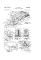
- FIGURE l is a front elevation illustrating the left-hand portion of a carpet loom embodying the present invention
- FIGURE 2 is a perspective view illustrating the righthand portion of a carpet loom
- FIGURE 3 is an enlarged front elevation illustrating mechanism constructed in accordance with the present invention operating to discharge a cop butt
- FIGURE 4 is a perspective view illustrating a shuttle constructed in accordance with the teachings of the present invention operating in connection With cop changing apparatus of the loom,
- FIGURE 5 is an enlarged transverse sectional view taken on the line 5 5 in FIGURE 4,
- FIGURE 6 is an enlarged transverse sectional view taken on the line 6-6 in FIGURE 4,
- FIGURE 7 is an enlarged transverse sectional view taken on the line '7--7 in FIGURE 4,
- FIGURE 8 is an enlarged side elevation illustrating the shuttle eye shown in FIGURE 4, and
- FIGURE 9 is an enlarged longitudinal sectional view taken on the line 9--9 in FIGURE 4.
- a yarn tensioning means in the form of a shuttle eye is laterally disposed with respect to the longitudinal channel B and includes a forwardly projecting portion C of diminishing cross-section defining a downwardly and rearwardly inclined yarn guiding surface.
- a laterally extending channel D is deiined by the downwardly and rearwardly inclined yarn guiding surface and the shuttle wood o1' body and serves as a passageway for the yarn during threading.
- the yarn is delivered during weaving under the control of the tensioning means E in the form of horizontal tension pads. It is important to note that the shuttle eye is disposed entirely on the yarn delivery side of the longitudinally disposed hook channel B so that the passageway B offers a minimum of obstruction to the passage of the hook and to threading.
- a cutting mechanism F is carried within the shuttle eye and when moved by the shuttle beneath the cam means A on an automatic change operation is actuated to cut or part the yarn Y from the last pick Woven into the fabric.
- the cam means A are actuated so as to be moved into position in alignment with the plunger of the cutting mechanism F which constitutes a means actuating the cutting mechanism responsive to the operation of the means automatically replenishing the filling supply.
- FIGURES l and 2 illustrate the left and right hand sides, respectively, of a carpet loom and the like. Thel 'up stroke of the lay 13.
- An automatic change operation in which a new cap is to be placed within the shuttle S replacing an exhausted cop, is initiated by a photo electric cell 23.
- a plate 24 having a light reflective upper surface is carried adjacent one end of the shuttle S so that when the filling supply becomes nearly exhausted only 4a Itail end or butt 25 remains, the light emitted by the photo electric cell 23 is reflected by the exposed upper surface of the plate 24 to actuate suitable pneumatic controller mechanism (not shown) for actuating the air cylinder 26.
- the air cylinder 26 is provided with suitable mounting means 27 carried by a bracket 28 mounted upon the lay.
- a mounting block 34 has fixed connection with the housing 32 by a pair of mounting arms 34a.
- the housing 32 is carried by a shaft 35 rotatably mounted in suitable bearing blocks 35a carried by the bracket 28.
- Al hook member 36 for removing the butt 25 of the cop is fixed to a pin 37 which is piovtally mounted within the mounting block 34.
- a link 38 has fixed connection with the pivoted pin 37 on one end and a coil spring 39 on the other end.
- the coil spring 39 is connected adjacent its other end to -the housing 32 as at 40.
- the hook 36 is adapted to engage the butt 25 of the cop against the force of the spring 39.
- the roller is rotatably mounted upon a stub shaft 42 carried 'by a slide 43 which is slidably carried within a housing 44 fixed to the loom sword 14.
- the slide is spring biased downwardly by the compression spring 45.
- the shuttle S is illustrated in FIGURE 4 as having a central cavity 46 for accommodating a filling supply in the form of a cop.
- a number of aligned spaced ⁇ tufls of bristles 47 project outwardly into the cavity on both sides and a resilient retaining element 48 is provided for retaining the filling supply within the cavity 46.
- One side of the shuttle S provides ⁇ an upper surface 49 for engagement by the roller 41 to positively position the shuttle.
- the longitudinally disposed hook channel B is disposed in alignment with the cavity 46 and the other side of the shuttle accommodates the shuttle eye in a cavity 5@ in such Ia manner that the shuttle eye is disposed substantially on one side of the hook channel B so that the hook channel B is clear for reception of the hook 36.
- the shaft 35 on its left hand end in FIGURES l and 3 is provided with a housing 51 fixed thereto.
- the housing 51 carries a roller mounting block 52 as by the rod supports 52a.
- the cam or roller A is rotatably mounted upon the stub shaft 53 tixedly carried within the support 52.
- the cam A Upon the occurrence of an automatic cop replenishing operation, the cam A is lowered into the position shown in FIGURES 3 and 4 to depress the button 54 which forms part of the means for actuating thecu'tting mechanism F.
- the shuttle block 55 is secured within the cavity 50 provided therefor by suitable bolts 56 which are threaded into the shuttle and into the block as at 57. It will be noted that the bolt 56 also passes through the base plate 58 and that the base plate is secured adjacent its forward portion as by the threaded bolt 59.
- the block 55 has an integral vforwardly projecting yarn guiding portion C which serves as a guide in threading the shuttle.
- the block and yarn guiding por-tion C form a vertical surface 60, which together with the vertical surface 61 of the shuttle body, dene the open hook passage B.
- the lowersurface 62 of the passage B inclines downwardly toward the rear to form a recess 63 (FIGURE 5) to accommodate the passage of yarn into the tensioning means E.
- the yarn guiding portion C has a downwardly and rearwardly inclined surface 64 for guiding the yarn downwardly within the passageway D to be received by the tensioning means E.
- the passageway D is joined with the lower portion of the passage 63 and provides for passage of the yarn around the projection C and into the tensioning means E.
- the passageway D is formed by the upper projection 65 of the shuttle wood or body and the face 64 of the projection C.
- the tensioning means E include an upper spring biased tension pad 66 and the base 58.
- the upper pad 66 is vertically movable and the spaced pins 67 acts as guides for such vertical movement and position the yarn Y for delivery from the delivery eye 68 at the side of the shuttle eye. rl ⁇ he upturned portion 66a, which extends into a cavity 55a within .the block, guides the yarn into delivery position under control of the tensioning means E.
- the tension upon the upper pad 66 is regulated by adjustment of the pair of longitudinally spaced springs 69 carried within the block 55. The springs are adjusted by turning the threaded elements 70, access to which may be had through an upper extension 72 of the bore 71.
- the cutting means F includes a blade 73 formed upon the upper side of a notch 74 within a fiat vertically disposed member 75.
- the blade member 75 is carried by a vertical spring biased plunger 76 which forms a part of the means for actuating the blade mechanism F.
- the blade portion 75 is accommodated within a slot 58a which is formed within the base 58.
- the blade 75 also passes through a slot 66]] within the upper tension pad 66 and is received within the opening within the housing 55a shaped to accommodate same.
- the plunger 76 passes through a bore 77 within the block 55 and a spring 78 is accommodated within an enlarged portion 77a of the bore 77.
- the cap 54 is accommodated within a still larger portion of the bore 77b and is threadably secured as at 76a to the cap 54.
- the block 55 has an upper surface 54a for rolling contact by the cam A to depress the cap 54.
- the yarn manipulating device illustrated herein is actuated by the automatic cop changing apparatus responsive to a signal that the filling supply is nearly exhausted.
- the shaft 35 is turned in a counterclockwise direction by the action of the air cylinder 26 in order to lower the hook 36 and the actuatingcam A into operative position to receive the shuttle S.
- the hook 36 passes longitudinally of the shuttle through the hook channel B..
- a filling manipulating device for a loom having a hook ejecting from a shuttle the butt of an exhausted cop and means automatically operating said hook including, an open vertical channel for said hook extending longitudinally of said shuttle, a shuttle eye mounted substantially on the yarn delivery side of said channel, yarn tensioning means carried by said eye, a yarn cutting mechanism carried by said eye in alignment with the yarn delivery, means actuating said cutting mechanism responsive to said means automatically operating said hook, said eye having a forwardly projecting portion of diminishing cross-section, and a downwardly and rearwardly inclined yarn guiding surface defined by said forwardly projecting portion, whereby yarn is guided on threading by the downwardly and rearwardly inclined surface into said tensioning means.
Landscapes
- Engineering & Computer Science (AREA)
- Textile Engineering (AREA)
- Looms (AREA)
Description
Aug. 11, 1964 A. G. KLocK FILLING MANIPULATING DEVICE 2 Sheets--Shceefl 1 Filed Feb. 28, 1961 INVENTOR;
ALBERT G. KLocK ATTORNEY Aug- 11, 1964 A. G. KLOCK 3,144,052
FILLING MANIPULATING DEVICE Filed Feb. 28 1961 2 .'SheetS-Sheetl 2 l E F''. :9 o JNVENTOR.
ALBERT G. KLocK ATTORNEY United States Patent O 3,144,652 FILLING MANIPULATING DEVICE Albert G. Kloek, Pipersville, Pa., assigner to Steel Heddle Manufacturing Company, Paris, S.C., a corporation of Pennsylvania Filed Feb. 28, 1951, Ser. No. 92,352 1 Claim. (Cl. 139-224) This invention relates to tilling manipulating devices and more especially to improved means for replenishing the filling supply of a shuttle and delivering filling from same.
The invention will be illustrated in connection with a carpet loom and shuttle for which the invention is particularly adapted for use. The loom illustrated includes Aa cop changer of the type illustrated in United States Letters Patent No. 2,871,889 known as the Egelhaaf Cop Changer.
In connection with carpet looms, the lling replenishing operation is especially important because the yarn is of a coarse type generally supplied in the form of a cop which becomes exhausted after about a 90 second run. In connection with the Egelhaaf Cop Changer, a hook is lowered toward the shuttle when the cop changing operation commences. As the shuttle moves beneath the hook, the hook passes longitudinally through the longitudinal yarn delivery channel into the cop storing cavity to engage and remove the butt of the cop to be discharged. One diiiiculty with removing the butt of the cop is that it is diiiicult to insure positive removal of the yarn forming the last pick from the delivery means of the shuttle. In order to disengage the last pick from the shuttle to avoid a double pick, it is necessary to disengage same from the yarn tensioning means. Yarn tensioning means are essential in weaving of this type in order to maintain a uniform tension of the pick yarn. `In order to make it possible for the hook to disengage this last pick, it was formerly necessary to place the tensioning devices within the longitudinal yarn delivery channel so that the hook may open them permitting removal of the final pick yarn as well as the butt of the cop. Because of this structural requirement it was difficult to get sufficient tension and yet provide a structure which permitted an entry by the hook. It is also diflicult to main- `tain suiiicient tension because if the tension be too great the coarse yarn will not thread into the pads after an automatic cop changing operation. Very often the shuttle becomes entirely unthreaded because of insufficient tension and this is known as a throw out. Thus, the action of removing the final pick of the shuttle is not positive and rethreading is not positive because of the difficulties introduced by the structure provided in the attempt to maintain a suitable and uniform tension.
Accordingly, it is an object of this invention to provide a cop shuttle which makes positive self-threading possible.
An important object of this invention is the provision of a shuttle having automatic means for severing the yarn from the iinal pick from the shuttle upon a supply changing operation.
Another object of the invention is the provision of a cop shuttle providing adjustable tension means for maintaining desired tension upon the yarn delivered therefrom` g p Another object of the invention is to provide tensioning means for a cop shuttle which will not interfere with the operation of removing the butt of the exhausted cop.
Still another object of the invention is to provide a positive means for severing the last filling from a cop shuttle without interfering with the cop changing opera- Ition.
Yet another object of the invention is to provide a loom 3,144,052 Patented Aug. l1, 1964 ice having means coacting with the shuttle for actuating means carried by the shuttle for severing the pick yarn therefrom preparatory to a supply changing operation.
The construction designed to carry out the invention will be hereinafter described, together with other features thereof.
The invention will be more readily understood from a reading of the following specification and by reference to the accompanying drawings forming a part thereof, wherein an example of the invention is shown and wherein:
FIGURE l is a front elevation illustrating the left-hand portion of a carpet loom embodying the present invention,
FIGURE 2 is a perspective view illustrating the righthand portion of a carpet loom,
FIGURE 3 is an enlarged front elevation illustrating mechanism constructed in accordance with the present invention operating to discharge a cop butt,
FIGURE 4 is a perspective view illustrating a shuttle constructed in accordance with the teachings of the present invention operating in connection With cop changing apparatus of the loom,
FIGURE 5 is an enlarged transverse sectional view taken on the line 5 5 in FIGURE 4,
FIGURE 6 is an enlarged transverse sectional view taken on the line 6-6 in FIGURE 4,
FIGURE 7 is an enlarged transverse sectional view taken on the line '7--7 in FIGURE 4,
FIGURE 8 is an enlarged side elevation illustrating the shuttle eye shown in FIGURE 4, and
FIGURE 9 is an enlarged longitudinal sectional view taken on the line 9--9 in FIGURE 4.
Referring more particularly to the drawings, a rug loom and the like is illustrated having automatically operable means replenishing the exhausted cops with full cops. Mechanism is included of the type employing a hook for removing the unused butt portion of the exhausted cop. Cam means A is actuated by turning same downwardly into operative position by the means automatically replenishing the filling supply during an automatic cop changing operation. This may be accomplished by the same means employed for turning the hook downwardly into operative position. A shuttle is illustrated having an unobstructed passageway B for receiving the hook member during a cop changing operation. A yarn tensioning means in the form of a shuttle eye is laterally disposed with respect to the longitudinal channel B and includes a forwardly projecting portion C of diminishing cross-section defining a downwardly and rearwardly inclined yarn guiding surface. A laterally extending channel D is deiined by the downwardly and rearwardly inclined yarn guiding surface and the shuttle wood o1' body and serves as a passageway for the yarn during threading. The yarn is delivered during weaving under the control of the tensioning means E in the form of horizontal tension pads. It is important to note that the shuttle eye is disposed entirely on the yarn delivery side of the longitudinally disposed hook channel B so that the passageway B offers a minimum of obstruction to the passage of the hook and to threading. A cutting mechanism F is carried within the shuttle eye and when moved by the shuttle beneath the cam means A on an automatic change operation is actuated to cut or part the yarn Y from the last pick Woven into the fabric. The cam means A are actuated so as to be moved into position in alignment with the plunger of the cutting mechanism F which constitutes a means actuating the cutting mechanism responsive to the operation of the means automatically replenishing the filling supply.
FIGURES l and 2 illustrate the left and right hand sides, respectively, of a carpet loom and the like. Thel 'up stroke of the lay 13.
loom frame provides support for the breast beam 11 adjacent the top of the swords as by bolts 17. The reed 18 is carried by the reed cap 16. The warp yarns W pass between the reed wires 18 and the filling yarn Y is beaten up into the fell 19 of the fabric R by each beat The shuttle S is propelled back and for-th across the lay 13 during the weaving operation and places the filling within the shed formed `by the warp yarns W by the action of the pickers 2i) carried by therusual picker sticks 21 positioned at each end 'of the loom. The shuttle S is boxed within suitable shuttle boxes, the shuttle box backs 22 being illustr-ated in FIG- `URES l and 2.
An automatic change operation, in which a new cap is to be placed within the shuttle S replacing an exhausted cop, is initiated by a photo electric cell 23. A plate 24 having a light reflective upper surface is carried adjacent one end of the shuttle S so that when the filling supply becomes nearly exhausted only 4a Itail end or butt 25 remains, the light emitted by the photo electric cell 23 is reflected by the exposed upper surface of the plate 24 to actuate suitable pneumatic controller mechanism (not shown) for actuating the air cylinder 26. The air cylinder 26 is provided with suitable mounting means 27 carried by a bracket 28 mounted upon the lay. Upon actuation by the photo electric cell 23, air is introduced into the front of the cylinder through a iiexiole tube 29 while air is withdrawn through the vflexible tube 30 from the rear of the `cylinder so that the piston rod 31 is urged rearwardly lturning the housing 32 to which the piston rod 31 has pivotal connection as at 33 (FIGURE 3) in a counter clockwise direction. A mounting block 34 has fixed connection with the housing 32 by a pair of mounting arms 34a. The housing 32 is carried by a shaft 35 rotatably mounted in suitable bearing blocks 35a carried by the bracket 28.
Al hook member 36 for removing the butt 25 of the cop is fixed to a pin 37 which is piovtally mounted within the mounting block 34. A link 38 has fixed connection with the pivoted pin 37 on one end and a coil spring 39 on the other end. The coil spring 39 is connected adjacent its other end to -the housing 32 as at 40. Referring especially to FIGURES 3 and 4, it will be noted that the hook 36 is adapted to engage the butt 25 of the cop against the force of the spring 39. Upon reception of the shuttle S on the battery side of the loom preparatory to a change operation, it will be noted that the shuttle is positively positioned during the butt hooking operation by a spring biased cam or roller 41. The roller is rotatably mounted upon a stub shaft 42 carried 'by a slide 43 which is slidably carried within a housing 44 fixed to the loom sword 14. The slide is spring biased downwardly by the compression spring 45. After the butt 25 has been removed the hook, which has been urged rearwardly against the force of the spring 39, moves forwardly and upwardly due to the force of the spring 39 and the upward movement of the mounting block 34 caused by rotation of the housing 32 in a clockwise direction resulting from the action of the air cylinder 26. In timed sequence with the above operation mechanism (not shown) is actua-ted for placing a full cop 25a from the battery or magazine M (FIGURE l) into the shuttle S.
The shuttle S is illustrated in FIGURE 4 as having a central cavity 46 for accommodating a filling supply in the form of a cop. A number of aligned spaced `tufls of bristles 47 project outwardly into the cavity on both sides and a resilient retaining element 48 is provided for retaining the filling supply within the cavity 46. One side of the shuttle S provides `an upper surface 49 for engagement by the roller 41 to positively position the shuttle. The longitudinally disposed hook channel B is disposed in alignment with the cavity 46 and the other side of the shuttle accommodates the shuttle eye in a cavity 5@ in such Ia manner that the shuttle eye is disposed substantially on one side of the hook channel B so that the hook channel B is clear for reception of the hook 36.
The shaft 35 on its left hand end in FIGURES l and 3 is provided with a housing 51 fixed thereto. The housing 51 carries a roller mounting block 52 as by the rod supports 52a. The cam or roller A is rotatably mounted upon the stub shaft 53 tixedly carried within the support 52. Upon the occurrence of an automatic cop replenishing operation, the cam A is lowered into the position shown in FIGURES 3 and 4 to depress the button 54 which forms part of the means for actuating thecu'tting mechanism F. The shuttle block 55 is secured within the cavity 50 provided therefor by suitable bolts 56 which are threaded into the shuttle and into the block as at 57. It will be noted that the bolt 56 also passes through the base plate 58 and that the base plate is secured adjacent its forward portion as by the threaded bolt 59.
As pointed out above the block 55 has an integral vforwardly projecting yarn guiding portion C which serves as a guide in threading the shuttle. The block and yarn guiding por-tion C form a vertical surface 60, which together with the vertical surface 61 of the shuttle body, dene the open hook passage B. The lowersurface 62 of the passage B inclines downwardly toward the rear to form a recess 63 (FIGURE 5) to accommodate the passage of yarn into the tensioning means E. The yarn guiding portion C has a downwardly and rearwardly inclined surface 64 for guiding the yarn downwardly within the passageway D to be received by the tensioning means E. The passageway D is joined with the lower portion of the passage 63 and provides for passage of the yarn around the projection C and into the tensioning means E. The passageway D is formed by the upper projection 65 of the shuttle wood or body and the face 64 of the projection C.
The tensioning means E include an upper spring biased tension pad 66 and the base 58. The upper pad 66 is vertically movable and the spaced pins 67 acts as guides for such vertical movement and position the yarn Y for delivery from the delivery eye 68 at the side of the shuttle eye. rl`he upturned portion 66a, which extends into a cavity 55a within .the block, guides the yarn into delivery position under control of the tensioning means E. The tension upon the upper pad 66 is regulated by adjustment of the pair of longitudinally spaced springs 69 carried within the block 55. The springs are adjusted by turning the threaded elements 70, access to which may be had through an upper extension 72 of the bore 71.
The cutting means F includes a blade 73 formed upon the upper side of a notch 74 within a fiat vertically disposed member 75. The blade member 75 is carried by a vertical spring biased plunger 76 which forms a part of the means for actuating the blade mechanism F. The blade portion 75 is accommodated within a slot 58a which is formed within the base 58. The blade 75 also passes through a slot 66]] within the upper tension pad 66 and is received within the opening within the housing 55a shaped to accommodate same. The plunger 76 passes through a bore 77 within the block 55 and a spring 78 is accommodated within an enlarged portion 77a of the bore 77. The cap 54 is accommodated within a still larger portion of the bore 77b and is threadably secured as at 76a to the cap 54. The block 55 has an upper surface 54a for rolling contact by the cam A to depress the cap 54.
In operation, the yarn manipulating device illustrated herein is actuated by the automatic cop changing apparatus responsive to a signal that the filling supply is nearly exhausted. The shaft 35 is turned in a counterclockwise direction by the action of the air cylinder 26 in order to lower the hook 36 and the actuatingcam A into operative position to receive the shuttle S. The hook 36 passes longitudinally of the shuttle through the hook channel B..
in order to remove the butt 25 of the cop and the cam A 5 depresses the cap 54 to actuate the mechanism F for severing or parting the yarn Y delivered from the shuttle on the last pick. After the yarn supply has been replenished from the magazine M on the first pick, the yarn from the new cop is within the yarn channel B and on the second pick is engaged by the forwardly projecting portion C and guided down the face of the shuttle eye 64 into the lateral yarn channel D and into the tensioning means E for delivery from the delivery eye 68. Thus, a positive effective means is provided for manipulating and controlling the tension of lling yarn on the transfer operation.
While a preferred embodiment of the invention has been described using specic terms, such description is for illustrative purposes only, and it is to be understood that changes and variations may be made without departing from the spirit or scope of the following claim.
What is claimed is:
A filling manipulating device for a loom having a hook ejecting from a shuttle the butt of an exhausted cop and means automatically operating said hook including, an open vertical channel for said hook extending longitudinally of said shuttle, a shuttle eye mounted substantially on the yarn delivery side of said channel, yarn tensioning means carried by said eye, a yarn cutting mechanism carried by said eye in alignment with the yarn delivery, means actuating said cutting mechanism responsive to said means automatically operating said hook, said eye having a forwardly projecting portion of diminishing cross-section, and a downwardly and rearwardly inclined yarn guiding surface defined by said forwardly projecting portion, whereby yarn is guided on threading by the downwardly and rearwardly inclined surface into said tensioning means.
References Cited in the le of this patent UNITED STATES PATENTS 467,803 Hall Ian. 26, 1892 1,268,136 McGuiness June 4, 1918 1,386,773 Fogle Aug. 9, 1921 1,794,024 Lucas Feb. 24, 1931 2,046,288 Davis June 30, 1936 2,801,649 Mulatti et al. Aug. 6, 1957 2,810,404 Chalmers et al. Oct. 22, 1957 2,871,889 Schlsser Feb. 3, 1959 2,943,649 Parks July 5, 1960 3,082,796 Schrder Mar. 26, 1963 FOREIGN PATENTS 632,245 Great Britain Nov. 18, 1949 821,008 Great Britain Sept. 30, 1959
Priority Applications (1)
| Application Number | Priority Date | Filing Date | Title |
|---|---|---|---|
| US92352A US3144052A (en) | 1961-02-28 | 1961-02-28 | Filling manipulating device |
Applications Claiming Priority (1)
| Application Number | Priority Date | Filing Date | Title |
|---|---|---|---|
| US92352A US3144052A (en) | 1961-02-28 | 1961-02-28 | Filling manipulating device |
Publications (1)
| Publication Number | Publication Date |
|---|---|
| US3144052A true US3144052A (en) | 1964-08-11 |
Family
ID=22232816
Family Applications (1)
| Application Number | Title | Priority Date | Filing Date |
|---|---|---|---|
| US92352A Expired - Lifetime US3144052A (en) | 1961-02-28 | 1961-02-28 | Filling manipulating device |
Country Status (1)
| Country | Link |
|---|---|
| US (1) | US3144052A (en) |
Cited By (4)
| Publication number | Priority date | Publication date | Assignee | Title |
|---|---|---|---|---|
| DE1535676B1 (en) * | 1965-06-26 | 1971-08-12 | Stienemann Karl Ludwig | Device for the automatic exchange of hose heads |
| US3604466A (en) * | 1968-09-20 | 1971-09-14 | Rueti Ag Maschf | Apparatus and method for cleaning a shuttle on a loom |
| US5641000A (en) * | 1994-04-27 | 1997-06-24 | Texo Ab | Automatic bobbin changing in a weaving machine |
| US20040129333A1 (en) * | 2003-01-07 | 2004-07-08 | Hiram Samel | Method for weaving floor coverings |
Citations (12)
| Publication number | Priority date | Publication date | Assignee | Title |
|---|---|---|---|---|
| US467803A (en) * | 1892-01-26 | Frank j | ||
| US1268136A (en) * | 1917-03-07 | 1918-06-04 | Crompton & Knowles Loom Works | Loom-shuttle. |
| US1386773A (en) * | 1920-12-15 | 1921-08-09 | Fogle David Herbert | Yarn-tensioning device for loom-shuttles |
| US1794024A (en) * | 1928-11-21 | 1931-02-24 | Lucas Lamborn Loom Corp | Bobbin-changing mechanism |
| US2046288A (en) * | 1936-01-24 | 1936-06-30 | Draper Corp | Shuttle tension |
| GB632245A (en) * | 1947-06-24 | 1949-11-18 | Derrick Walter Shimwell | Improvements relating to automatic looms for weaving |
| US2801649A (en) * | 1952-04-10 | 1957-08-06 | Coll Adriano Gardella & Fllo S | Shuttle-loading device for automatic looms for weaving |
| US2810404A (en) * | 1955-07-18 | 1957-10-22 | Joseph W Chalmers | Automatic threading shuttle |
| US2871889A (en) * | 1955-01-15 | 1959-02-03 | Laval Separator Co De | Method and means for the automatic exchange of weft cops on looms |
| GB821008A (en) * | 1957-10-08 | 1959-09-30 | Hermann Held | A threading and guiding means for the weft thread in shuttles with automatic ejection of the cop residue |
| US2943649A (en) * | 1956-12-31 | 1960-07-05 | Robert F Parks | Filling control device |
| US3082796A (en) * | 1957-10-08 | 1963-03-26 | C C Egelhaaf Kommanditgesellsc | Threading and guiding means for the weft thread in shuttles with automatic ejection of the cop residue |
-
1961
- 1961-02-28 US US92352A patent/US3144052A/en not_active Expired - Lifetime
Patent Citations (12)
| Publication number | Priority date | Publication date | Assignee | Title |
|---|---|---|---|---|
| US467803A (en) * | 1892-01-26 | Frank j | ||
| US1268136A (en) * | 1917-03-07 | 1918-06-04 | Crompton & Knowles Loom Works | Loom-shuttle. |
| US1386773A (en) * | 1920-12-15 | 1921-08-09 | Fogle David Herbert | Yarn-tensioning device for loom-shuttles |
| US1794024A (en) * | 1928-11-21 | 1931-02-24 | Lucas Lamborn Loom Corp | Bobbin-changing mechanism |
| US2046288A (en) * | 1936-01-24 | 1936-06-30 | Draper Corp | Shuttle tension |
| GB632245A (en) * | 1947-06-24 | 1949-11-18 | Derrick Walter Shimwell | Improvements relating to automatic looms for weaving |
| US2801649A (en) * | 1952-04-10 | 1957-08-06 | Coll Adriano Gardella & Fllo S | Shuttle-loading device for automatic looms for weaving |
| US2871889A (en) * | 1955-01-15 | 1959-02-03 | Laval Separator Co De | Method and means for the automatic exchange of weft cops on looms |
| US2810404A (en) * | 1955-07-18 | 1957-10-22 | Joseph W Chalmers | Automatic threading shuttle |
| US2943649A (en) * | 1956-12-31 | 1960-07-05 | Robert F Parks | Filling control device |
| GB821008A (en) * | 1957-10-08 | 1959-09-30 | Hermann Held | A threading and guiding means for the weft thread in shuttles with automatic ejection of the cop residue |
| US3082796A (en) * | 1957-10-08 | 1963-03-26 | C C Egelhaaf Kommanditgesellsc | Threading and guiding means for the weft thread in shuttles with automatic ejection of the cop residue |
Cited By (4)
| Publication number | Priority date | Publication date | Assignee | Title |
|---|---|---|---|---|
| DE1535676B1 (en) * | 1965-06-26 | 1971-08-12 | Stienemann Karl Ludwig | Device for the automatic exchange of hose heads |
| US3604466A (en) * | 1968-09-20 | 1971-09-14 | Rueti Ag Maschf | Apparatus and method for cleaning a shuttle on a loom |
| US5641000A (en) * | 1994-04-27 | 1997-06-24 | Texo Ab | Automatic bobbin changing in a weaving machine |
| US20040129333A1 (en) * | 2003-01-07 | 2004-07-08 | Hiram Samel | Method for weaving floor coverings |
Similar Documents
| Publication | Publication Date | Title |
|---|---|---|
| US3144052A (en) | Filling manipulating device | |
| US2791242A (en) | Automatic filling rake | |
| US2250866A (en) | Weft end control means | |
| US3067778A (en) | Braking device for thread for an automatic loom | |
| US2528150A (en) | Shuttle box mechanism for weft replenishing looms | |
| US1511183A (en) | Filling-replenishing loom | |
| US1727315A (en) | Thread positioner for filling replenishing looms | |
| US2716429A (en) | Device for applying tension to yarn | |
| US2202226A (en) | Filling end control | |
| US1132227A (en) | Filling-end controller for looms. | |
| US1939864A (en) | Fabric and method and apparatus for producing it | |
| US2263983A (en) | Stopping mechanism for weft replenishing looms | |
| US1881920A (en) | Thread parter for weft replenishing looms | |
| US1741324A (en) | Thread control for loom thread cutters | |
| US1786659A (en) | Weft-replenishing loom | |
| US448202A (en) | bowker | |
| US2593302A (en) | Weft yarn ensnaring apparatus for automatic looms | |
| US604632A (en) | Thread-cutting temple for looms | |
| US2233373A (en) | Filling end remover | |
| US1647731A (en) | Thread cutter for weft-replenishing looms | |
| US2721583A (en) | Electrical circuit controlling thread cutter for looms | |
| US2723684A (en) | Self-threading loom shuttles | |
| US1287102A (en) | Filling-replenishing loom. | |
| US724120A (en) | Filling-replenishing loom. | |
| US683423A (en) | Thread-parting mechanism for looms. |