US3338436A - Means for coupling loads to lifting means - Google Patents
Means for coupling loads to lifting means Download PDFInfo
- Publication number
- US3338436A US3338436A US552620A US55262066A US3338436A US 3338436 A US3338436 A US 3338436A US 552620 A US552620 A US 552620A US 55262066 A US55262066 A US 55262066A US 3338436 A US3338436 A US 3338436A
- Authority
- US
- United States
- Prior art keywords
- load
- mast
- frame
- chassis
- supported
- Prior art date
- Legal status (The legal status is an assumption and is not a legal conclusion. Google has not performed a legal analysis and makes no representation as to the accuracy of the status listed.)
- Expired - Lifetime
Links
Images

Classifications
-
- B—PERFORMING OPERATIONS; TRANSPORTING
- B66—HOISTING; LIFTING; HAULING
- B66C—CRANES; LOAD-ENGAGING ELEMENTS OR DEVICES FOR CRANES, CAPSTANS, WINCHES, OR TACKLES
- B66C1/00—Load-engaging elements or devices attached to lifting or lowering gear of cranes or adapted for connection therewith for transmitting lifting forces to articles or groups of articles
- B66C1/10—Load-engaging elements or devices attached to lifting or lowering gear of cranes or adapted for connection therewith for transmitting lifting forces to articles or groups of articles by mechanical means
- B66C1/62—Load-engaging elements or devices attached to lifting or lowering gear of cranes or adapted for connection therewith for transmitting lifting forces to articles or groups of articles by mechanical means comprising article-engaging members of a shape complementary to that of the articles to be handled
- B66C1/66—Load-engaging elements or devices attached to lifting or lowering gear of cranes or adapted for connection therewith for transmitting lifting forces to articles or groups of articles by mechanical means comprising article-engaging members of a shape complementary to that of the articles to be handled for engaging holes, recesses, or abutments on articles specially provided for facilitating handling thereof
-
- B—PERFORMING OPERATIONS; TRANSPORTING
- B60—VEHICLES IN GENERAL
- B60P—VEHICLES ADAPTED FOR LOAD TRANSPORTATION OR TO TRANSPORT, TO CARRY, OR TO COMPRISE SPECIAL LOADS OR OBJECTS
- B60P1/00—Vehicles predominantly for transporting loads and modified to facilitate loading, consolidating the load, or unloading
- B60P1/54—Vehicles predominantly for transporting loads and modified to facilitate loading, consolidating the load, or unloading using cranes for self-loading or self-unloading
-
- B—PERFORMING OPERATIONS; TRANSPORTING
- B66—HOISTING; LIFTING; HAULING
- B66F—HOISTING, LIFTING, HAULING OR PUSHING, NOT OTHERWISE PROVIDED FOR, e.g. DEVICES WHICH APPLY A LIFTING OR PUSHING FORCE DIRECTLY TO THE SURFACE OF A LOAD
- B66F9/00—Devices for lifting or lowering bulky or heavy goods for loading or unloading purposes
- B66F9/06—Devices for lifting or lowering bulky or heavy goods for loading or unloading purposes movable, with their loads, on wheels or the like, e.g. fork-lift trucks
- B66F9/075—Constructional features or details
- B66F9/08—Masts; Guides; Chains
- B66F9/10—Masts; Guides; Chains movable in a horizontal direction relative to truck
-
- B—PERFORMING OPERATIONS; TRANSPORTING
- B66—HOISTING; LIFTING; HAULING
- B66F—HOISTING, LIFTING, HAULING OR PUSHING, NOT OTHERWISE PROVIDED FOR, e.g. DEVICES WHICH APPLY A LIFTING OR PUSHING FORCE DIRECTLY TO THE SURFACE OF A LOAD
- B66F9/00—Devices for lifting or lowering bulky or heavy goods for loading or unloading purposes
- B66F9/06—Devices for lifting or lowering bulky or heavy goods for loading or unloading purposes movable, with their loads, on wheels or the like, e.g. fork-lift trucks
- B66F9/075—Constructional features or details
- B66F9/12—Platforms; Forks; Other load supporting or gripping members
- B66F9/18—Load gripping or retaining means
Definitions
- This invention relates to means for coupling loads to lifting means. While the invention is primarily intended for use with side loading fork lift trucks and is hereinafter described in relation to such trucks, it is to be understood that it could equally well be adapted for use with front loading fork lift trucks or indeed other forms of lifting means.
- means for coupling a load to lifting mean-s comprises one member adapted to be secured to the load and arranged for interengagement with another member adapted to be secured to the lifting means, one member comprising a channel section sleeve having inwardly directed horizontal flanges and the other member comprising a beam having outwardly directed horizontal flanges, the arrangement being such that in use the sleeve and beam may be slidden longitudinally together to bring the flanges of the sleeve and beam into engagement.
- the channel section sleeve is secured to the load and the beam comprises the load lifting means of a fork lift industrial truck.
- the beam comprises the load lifting means of a fork lift industrial truck.
- two sleeves are normally provided for inter-engagement with two beams comprising the works of the industrial truck.
- the sleeves should be secured to the upper surface of the load to be lifted.
- the sleeves may, in fact, either be secured permanently to the upper surface of the load when the load comprises, for example, a container which is constantly to be lifted or alternatively may be adapted to be secured to the load by being formed as part of a jig or pallet in or on which the load is to be placed.
- the beams are most conveniently formed of I section so that the upper surface of the I can be used in a conventional manner for insertion under loads, whereas the bottom surface of the I provides flanges for engagement under the flanges of the sleeves.
- standard forks may be adapted by providing a sleeve to be slidden longitudinally on to the forks, the said sleeve having a depending I section being secured to its lower surface.
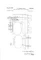
- FIGURE 1 is a diagrammatic view from the rear end of a side-loading fork lift truck alongside a railway wagon showing the movement of a load in the form of a bulk liquid tank from one vehicle to the other;
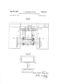
- FIGURE 2 is a diagrammatic view from the left of FIGURE 1 of the central portion of the side-loader truck chassis showing details of the load moving means;
- FIGURE 3 is a detailed plan view of part of FIG- URE 2
- FIGURE 4 is a cross section of a different flanged lifting device.
- FIGURES 1 to 3 show means for coupling a load to lifting means in which the lifting means is mounted on a side-loader fork lift truck 1 and 3,338,436 Patented Aug. 29, 1967 the load is a bulk tank 2 for use on a railway truck 3 and liftable therefrom for example on to a road transport vehicle or, for transporting on the side-loader truck 1.
- the tank 2 has secured thereto a flanged member 4 in the form of a channel section 5, with a central opening 5 in the top, mounted on a bracket 6.
- the bracket 6 is shown as fixed permanently to the tank, but it may be secured to means such as a strap which passes round the tank and can be removed and applied to another tank or like load.
- the truck 1 is a side-loader having a chassis formed of two body sections 6a and 6b interconnected by a rigid back structure 60, the body section 6b having the drivers cab 6d mounted thereon and prime mover mounted in 6a or 617 in the conventional manner.
- the gap 8a in the chassis has horizontal tracks 8 in which a mast 7 is supported on rollers 7a to enable the mast to move from the position in FIGURE 1 to the left hand side of the chassis in FIGURE 1 thereby moving the load carrying means to be described outside the chassis to lift the tank 2 and move it off the truck 3 to a point within the width of the chassis as in FIGURE 1.
- the mast 7 is movable convention-ally transversely of the truck in the guides 8 indicated diagrammatically in the drawings.
- the mast 7 supports a carriage 21 which is moved up and down within the sliding part 22 of the mast by power operated means shown as hydraulic cylinders 22a; also the carriage 21 can move up and down in the sliding mast part 22 under the action of a power operated chain 24: this construction is conventional and the carriage 21 normally has the forks of a fork lift arrangement pivoted thereto at 25.
- the forks have been removed and two beams 9 to be described are each pivoted at 25 at their inner ends to the carriage 2 1, the beams each having a downwardly extending bracket 26 rigid therewith;
- the carriage 21 has a conventional hydraulic cylinder 27 for each beam actuating a bell-crank lever 28 pivoted thereto, the lever 28 carrying a roller 29 riding against the bracket 26.
- the roller 29 moves the lower end of the bracket outwardly tilting the beam in the vertical plane about the pivot 25.
- the beams 9 can be raised and lowered on the mast and can also be tilted in the vertical plane with respect to the mast, thus providing two movements by which the position of the load can be adjusted in the vertical plane.
- the brackets 26 are shown with a guard member in the form of a rubber or like pad 11 to cushion the tank should it swing as it is moved by the aforesaid apparatus.
- the two beams 9 extend outwardly from the mast to a distance, shown in FIGURE 1 as almost the full width of the truck but it could extend further than the truck if desired.
- the outward ends of the beams 9 are crossbraced by girders or like members 30 rigidly secured at their ends to the beam and at each end have spaced projecting lugs 31; thus the beams 9 and the girders 30 form a rigid structure and the girders 30 are spaced apart so as to accommodate between them, supported on the beams 9, a load carrying beam shown in the drawings as a pair of beams 14 which at their ends are rigidly secured to the load carrying members 13 carrying at their lower ends flanges 12 which inter-engage with boxes 5 secured to the tank 2.
- each of the beams 14 is pivoted a hydraulic cylinder 18 and extending from each is a piston rod 19 connected by a ball joint at 34 to a cross bar 35 extending between and connected to the right hand ends of the girders 30 (FIG. 2).
- the cylinders 18 can both be actuated in the same way so that the beam 14 will pivot about the upper end of the links 15a and 15b thereby tilting the load in the vertical plane running parallel to the fore and aft axes of the vehicle. If, however, only one of the hydraulic cylinders 18 is actuated the link 15b will permit, in addition to the aforesaid fore and aft tilting of the load, a movement of the load about the upper pivot of the fixed link 15a thereby giving an additional slewing movement to the load.
- a hydraulic cylinder 20 Fixed to at least one of the beams 9 is a hydraulic cylinder 20 the piston rod of which is pivoted at 36 to brackets 37 fast on the beam 14; if the cylinder is actuated this will cause the beam 14 to tilt about the ball joint at the bottom of the lever 15b and the pivot 36 at the bottom right hand corner of the girder 30 in FIGURE 3 thereby tilting the load. in the vertical plane transversely of the vehicle.
- the load can be adjusted in all directions thereby facilitating its accurate placing on the truck 3 and enabling the flanges 12 to be engaged very accurately in the boxes on the tank 2 when the latter is on the truck 3 or any other support.
- All the aforesaid hydraulic cylinders are provided with hydraulic fluid from flexible fluid ducts (not shown) from a pressure tank on the vehicle through a valve located preferably in a valve bank (not shown) in the drivers cab.
- a valve located preferably in a valve bank (not shown) in the drivers cab.
- the driver cannot only control his vehicle with regard to its position with respect to the truck 3 but can also with accuracy introduce his load lifting means, i.e. the flange 12, into the boxes 5 of the tank to be lifted from a truck 3 without causing any damage to the tank.
- Each of the aforesaid tilting and slewing movements can be through an angular distance of at least 4 either side of the central position.
- the load can be adjusted by tilting or slewing to dispose the members 13 at the correct angle to the axes through the boxes 5.
- a heavy load can be lifted onto and off a truck 2 or other support and may be
- the construction in FIGURE 4 shows a normal fork supported by the truck 1.
- the mast 7 is moved out of the truck 1 along guides 8 to move them into the boxes.
- the I-bearn or its equivalent in FIGURES l-3 may be on the load and then the box 5 is on the member 13.
- the advantage of the said construction is that the load a bearing part of the lifting mechanism constitutes only part of the height of the fork beam 9 or member 13 and supports the load from above. This means the strains in the load can be distributed along the length of the load in the direction of the arrows 23 in FIGURE 2 instead of being concentrated on the fork engaging portions under the load. The bottom of the load or the supports for it can thus be shorter in height than in conventional under-load fork receiving portions.
- a load transfer vehicle for moving bulk loads e.g. bulk load containers between railway wagons and other wagons, said vehicle comprising a wheeled chassis, a load lifting and moving apparatus supported on the chassis having a mast mova ble with respect to the chassis, a substantially horizontal frame supported on said mast and power operated means for raising and lowering said frame with respect to said mast, a beam universally supported by said frame, lifting tackle comprising a first co-operating member forming part of said beam, and a.
- second co-opcrating member having means for rigidly securing it to the upper portion of a bulk load to be moved, one of said co-operating members having a channel section sleeve with inwardly directed horizontal flanges and the other of said co-operating members having outwardly directed horizontal flanges, power operated means mounted between said frame and said beam operable to tilt and slew said cooperating members and said load supported therefrom in three mutually perpendicular directions with respect to said chassis, said first cooperating member of said lifting tackle, by operation of said beam, can be slidden longitudinally with respect to the other member when secured to the load so that the lifting and moving apparatus can be operated to lift the load from above the load at one location, e.g. on a railway wagon, and moved to another location such as another vehicle platform.
- a load transfer vehicle characterised in that said sleeve is securely mountable on said load and the other co-operating member is part of said load lifting tackle movably supported on said frame, said sleeve having a slot in its upper wall along which said flanged co-operating member passes as the latter moves into and along said sleeve.
- a load transfer vehicle characterised in that the other of said coopearting members is of I-section the lower flanges of which constitute said first co-operating member.
- a side loader load transfer vehicle for moving bulk loads comprising a wheeled chassis
- the Vehicle as defined in claim 4 including an extensible link acting between said frame and said beam assembly in a direction transverse of said vehicle but longitudinally spaced with respect to said first link.
- a side loader load transfer vehicle for moving bulk loads comprising a wheeled chassis
- said beam assembly ing means comprises a ball joint joining said beam as- 10 sembly to said frame, a fixed length link, and ball joints pivotally connecting the opposite ends of said fixed length link to said frame and said beam assembly respectively.
- said power means comprises a pair of extensible links joining said beam assembly and said frame.
Landscapes
- Engineering & Computer Science (AREA)
- Transportation (AREA)
- Structural Engineering (AREA)
- Mechanical Engineering (AREA)
- Civil Engineering (AREA)
- Life Sciences & Earth Sciences (AREA)
- Geology (AREA)
- Forklifts And Lifting Vehicles (AREA)
Description
Aug. 29, 1967 G. N. BOWMAN-SHAW 3,338fi36 MEANS FOR COUPLING LOADS TO LIFTING MEANS 5 Sheets-Sheet 1 Filed May 24, 1966 Inventor wm -5Ymw By W AHor Filed May 24. 1966 N. BOWMAN-SHAW MEANS FOR COUPLING LOADS TO LIFTING MEANS 3 Sheets-Sheet 2 Inventor G ory: w/d Bamnrur- 4w 29, 1967 G. N. BOWMAN-SHAW 3,333,435
MEANS FOR COUPLING LOADS TO LIFTING MEANS Filed May 24, 1966 I5 Sheets-Sheet 3 Inventor United States Patent f 3,338,436 MEANS FOR COUPLING LOADS TO LIFTING MEANS George Neville Bowman-Shaw, Toddington Park, Toddington, England Filed May 24, 1966, Ser. No. 552,620 Claims priority, application Great Britain, Mar. 22, 1963, 11,439/ 63 8 Claims. (Cl. 214-75) This application is a continuation-in-part of applicants copending application S.N. 352,852, filed Mar. 18, 1964, now abandoned.
This invention relates to means for coupling loads to lifting means. While the invention is primarily intended for use with side loading fork lift trucks and is hereinafter described in relation to such trucks, it is to be understood that it could equally well be adapted for use with front loading fork lift trucks or indeed other forms of lifting means. According to the present invention means for coupling a load to lifting mean-s comprises one member adapted to be secured to the load and arranged for interengagement with another member adapted to be secured to the lifting means, one member comprising a channel section sleeve having inwardly directed horizontal flanges and the other member comprising a beam having outwardly directed horizontal flanges, the arrangement being such that in use the sleeve and beam may be slidden longitudinally together to bring the flanges of the sleeve and beam into engagement.
Preferably the channel section sleeve is secured to the load and the beam comprises the load lifting means of a fork lift industrial truck. In this case two sleeves are normally provided for inter-engagement with two beams comprising the works of the industrial truck.
It is also preferred that the sleeves should be secured to the upper surface of the load to be lifted. The sleeves may, in fact, either be secured permanently to the upper surface of the load when the load comprises, for example, a container which is constantly to be lifted or alternatively may be adapted to be secured to the load by being formed as part of a jig or pallet in or on which the load is to be placed.
The beams are most conveniently formed of I section so that the upper surface of the I can be used in a conventional manner for insertion under loads, whereas the bottom surface of the I provides flanges for engagement under the flanges of the sleeves.
Alternatively, rather than provide a fork lift truck with special fork members, standard forks may be adapted by providing a sleeve to be slidden longitudinally on to the forks, the said sleeve having a depending I section being secured to its lower surface.
In order that the invention may be more clearly understood some embodiments in accordance therewith will now be described with reference to the accompanying drawings, in which:
FIGURE 1 is a diagrammatic view from the rear end of a side-loading fork lift truck alongside a railway wagon showing the movement of a load in the form of a bulk liquid tank from one vehicle to the other;
FIGURE 2 is a diagrammatic view from the left of FIGURE 1 of the central portion of the side-loader truck chassis showing details of the load moving means;
FIGURE 3 is a detailed plan view of part of FIG- URE 2, and
FIGURE 4 is a cross section of a different flanged lifting device.
Referring to FIGURES 1 to 3 these show means for coupling a load to lifting means in which the lifting means is mounted on a side-loader fork lift truck 1 and 3,338,436 Patented Aug. 29, 1967 the load is a bulk tank 2 for use on a railway truck 3 and liftable therefrom for example on to a road transport vehicle or, for transporting on the side-loader truck 1.
The tank 2 has secured thereto a flanged member 4 in the form of a channel section 5, with a central opening 5 in the top, mounted on a bracket 6. The bracket 6 is shown as fixed permanently to the tank, but it may be secured to means such as a strap which passes round the tank and can be removed and applied to another tank or like load.
The truck 1 is a side-loader having a chassis formed of two body sections 6a and 6b interconnected by a rigid back structure 60, the body section 6b having the drivers cab 6d mounted thereon and prime mover mounted in 6a or 617 in the conventional manner. The gap 8a in the chassis has horizontal tracks 8 in which a mast 7 is supported on rollers 7a to enable the mast to move from the position in FIGURE 1 to the left hand side of the chassis in FIGURE 1 thereby moving the load carrying means to be described outside the chassis to lift the tank 2 and move it off the truck 3 to a point within the width of the chassis as in FIGURE 1. The mast 7 is movable convention-ally transversely of the truck in the guides 8 indicated diagrammatically in the drawings. The mast 7 supports a carriage 21 which is moved up and down within the sliding part 22 of the mast by power operated means shown as hydraulic cylinders 22a; also the carriage 21 can move up and down in the sliding mast part 22 under the action of a power operated chain 24: this construction is conventional and the carriage 21 normally has the forks of a fork lift arrangement pivoted thereto at 25. In the present invention the forks have been removed and two beams 9 to be described are each pivoted at 25 at their inner ends to the carriage 2 1, the beams each having a downwardly extending bracket 26 rigid therewith; the carriage 21 has a conventional hydraulic cylinder 27 for each beam actuating a bell-crank lever 28 pivoted thereto, the lever 28 carrying a roller 29 riding against the bracket 26. Thus on operation of the cylinder 27 the roller 29 moves the lower end of the bracket outwardly tilting the beam in the vertical plane about the pivot 25.
It will thus be seen that by means of the aforesaid construction of the truck and its mast the beams 9 can be raised and lowered on the mast and can also be tilted in the vertical plane with respect to the mast, thus providing two movements by which the position of the load can be adjusted in the vertical plane. The brackets 26 are shown with a guard member in the form of a rubber or like pad 11 to cushion the tank should it swing as it is moved by the aforesaid apparatus.
The two beams 9 extend outwardly from the mast to a distance, shown in FIGURE 1 as almost the full width of the truck but it could extend further than the truck if desired. The outward ends of the beams 9 are crossbraced by girders or like members 30 rigidly secured at their ends to the beam and at each end have spaced projecting lugs 31; thus the beams 9 and the girders 30 form a rigid structure and the girders 30 are spaced apart so as to accommodate between them, supported on the beams 9, a load carrying beam shown in the drawings as a pair of beams 14 which at their ends are rigidly secured to the load carrying members 13 carrying at their lower ends flanges 12 which inter-engage with boxes 5 secured to the tank 2. Two boxes 5 in fact are shown in the drawings spaced apart along the tank equi-distance from the vertical plane containing the centre of gravity of the tank. Additional boxes 5 may be provided if necessary. On each girder 30 the lugs 31 at each end provide the mounting means for supporting the beams 14. At the left hand end of the top beam 30 in FIGURE 3 a rigid link 15a is secured between the lug 31, the top 3 end of this link being connected to the beam 14 by a ball joint. At the left hand end of the bottom girder 30 in FIGURE 3 there is a link 15b seen also in FIGURE 2 which is connected at its lower end to the girder 30 by a ball joint 16 and at its upper end to the girder 14 by a ball joint 16a. At the right hand end of each of the beams 14 is pivoted a hydraulic cylinder 18 and extending from each is a piston rod 19 connected by a ball joint at 34 to a cross bar 35 extending between and connected to the right hand ends of the girders 30 (FIG. 2).
From the aforesaid description of the mounting of the members 14 on the beams 9 it can be seen that the cylinders 18 can both be actuated in the same way so that the beam 14 will pivot about the upper end of the links 15a and 15b thereby tilting the load in the vertical plane running parallel to the fore and aft axes of the vehicle. If, however, only one of the hydraulic cylinders 18 is actuated the link 15b will permit, in addition to the aforesaid fore and aft tilting of the load, a movement of the load about the upper pivot of the fixed link 15a thereby giving an additional slewing movement to the load. Fixed to at least one of the beams 9 is a hydraulic cylinder 20 the piston rod of which is pivoted at 36 to brackets 37 fast on the beam 14; if the cylinder is actuated this will cause the beam 14 to tilt about the ball joint at the bottom of the lever 15b and the pivot 36 at the bottom right hand corner of the girder 30 in FIGURE 3 thereby tilting the load. in the vertical plane transversely of the vehicle.
By these additional slewing and tilting movements of the load in addition to those described with reference to the tilting about the mast, it can be seen that the load can be adjusted in all directions thereby facilitating its accurate placing on the truck 3 and enabling the flanges 12 to be engaged very accurately in the boxes on the tank 2 when the latter is on the truck 3 or any other support.
All the aforesaid hydraulic cylinders are provided with hydraulic fluid from flexible fluid ducts (not shown) from a pressure tank on the vehicle through a valve located preferably in a valve bank (not shown) in the drivers cab. By this means the driver cannot only control his vehicle with regard to its position with respect to the truck 3 but can also with accuracy introduce his load lifting means, i.e. the flange 12, into the boxes 5 of the tank to be lifted from a truck 3 without causing any damage to the tank. Each of the aforesaid tilting and slewing movements can be through an angular distance of at least 4 either side of the central position.
The load can be adjusted by tilting or slewing to dispose the members 13 at the correct angle to the axes through the boxes 5. Thus a heavy load can be lifted onto and off a truck 2 or other support and may be The construction in FIGURE 4 shows a normal fork supported by the truck 1. Once the members 13 are in alignment with the boxes 5 the mast 7 is moved out of the truck 1 along guides 8 to move them into the boxes. 21 on which is a sleeve 22 carrying the I-beam 23 the lower flange of which engages the box 5 on the load. The I-bearn or its equivalent in FIGURES l-3 may be on the load and then the box 5 is on the member 13.
The advantage of the said construction is that the load a bearing part of the lifting mechanism constitutes only part of the height of the fork beam 9 or member 13 and supports the load from above. This means the strains in the load can be distributed along the length of the load in the direction of the arrows 23 in FIGURE 2 instead of being concentrated on the fork engaging portions under the load. The bottom of the load or the supports for it can thus be shorter in height than in conventional under-load fork receiving portions.
I claim:
1. A load transfer vehicle for moving bulk loads e.g. bulk load containers between railway wagons and other wagons, said vehicle comprising a wheeled chassis, a load lifting and moving apparatus supported on the chassis having a mast mova ble with respect to the chassis, a substantially horizontal frame supported on said mast and power operated means for raising and lowering said frame with respect to said mast, a beam universally supported by said frame, lifting tackle comprising a first co-operating member forming part of said beam, and a. second co-opcrating member having means for rigidly securing it to the upper portion of a bulk load to be moved, one of said co-operating members having a channel section sleeve with inwardly directed horizontal flanges and the other of said co-operating members having outwardly directed horizontal flanges, power operated means mounted between said frame and said beam operable to tilt and slew said cooperating members and said load supported therefrom in three mutually perpendicular directions with respect to said chassis, said first cooperating member of said lifting tackle, by operation of said beam, can be slidden longitudinally with respect to the other member when secured to the load so that the lifting and moving apparatus can be operated to lift the load from above the load at one location, e.g. on a railway wagon, and moved to another location such as another vehicle platform.
2. A load transfer vehicle according to claim 1 characterised in that said sleeve is securely mountable on said load and the other co-operating member is part of said load lifting tackle movably supported on said frame, said sleeve having a slot in its upper wall along which said flanged co-operating member passes as the latter moves into and along said sleeve.
3. A load transfer vehicle according to claim 1 characterised in that the other of said coopearting members is of I-section the lower flanges of which constitute said first co-operating member.
4. A side loader load transfer vehicle for moving bulk loads, comprising a wheeled chassis,
a vertical mast mounted on said chassis for movement with respect to said chassis transversely thereof,
a substantially horizontal frame slidably mounted on said mast and projecting transversely of the vehicle therefrom,
means for vertically moving said frame on said mast,
a beam assembly extending transversely of and above the free end of said frame,
a first link anchored to said frame and projecting upwardly therefrom, a ball joint connecting the upper end of said first link to said beam assembly,
a second link aligned longitudinally of said vehicle with respect to said first link but spaced therefrom transversely of said vehicle, ball joints at the opposite ends of said second link and joining same to said frame and said beam assembly respectively,
a pair of extensible links aligned longitudinally of the vehicle but transversely spaced with respect to each other and in longitudinally spaced relation to said first link,
and means selectively for individually and collectively extending said extensible links.
5. The Vehicle as defined in claim 4 including an extensible link acting between said frame and said beam assembly in a direction transverse of said vehicle but longitudinally spaced with respect to said first link.
6. A side loader load transfer vehicle for moving bulk loads, comprising a wheeled chassis,
a vertical mast mounted on said chassis for movement transversely thereof,
a substantially horizontal frame mounted on said mast for vertical movement thereon and projecting therefrom transversely of said chassis,
a load-engageable beam assembly extending longitudinally of said chassis for movement vertically and transversely with said frame, said beam assembly ing means comprises a ball joint joining said beam as- 10 sembly to said frame, a fixed length link, and ball joints pivotally connecting the opposite ends of said fixed length link to said frame and said beam assembly respectively.
8. The vehicle according to claim 7 wherein said power means comprises a pair of extensible links joining said beam assembly and said frame.
5 References Cited UNITED STATES PATENTS 2,271,776 2/ 1942 Minty 294-67 2,720,993 10/ 1955 Lull 2l4670 3,176,866 4/1965 Meister 2l4620 GERALD M. FORLENZA, Primary Examiner.
ROBERT G. SHERIDAN, Examiner.
Claims (1)
1. A LOAD TRANSFER VEHICLE FOR MOVING BULK LOADS E.G. BULK LOAD CONTAINERS BETWEEN RAILWAY WAGONS AND OTHER WAGONS, SAID VEHICLE COMPRISING A WHEELED CHASSIS, A LOAD LIFTING AND MOVING APPARATUS SUPPORTED ON THE CHASSIS HAVING A MAST MOVABLE WITH RESPECT TO THE CHASSIS, A SUB STANTIALLY HORIZONTAL FRAME SUPPORTED ON SAID MAST AND POWER OPERATED MEANS FOR RAISING AND LOWERING SAID FRAME WITH RESPECT TO SAID MAST, A BEAM UNIVERSALLY SUPPORTED BY SAID FRAME, LIFTING TACKLE COMPRISING A FIRST CO-OPERATING MEMBER FORMING PART OF SAID BEAM, AND A SECOND CO-OPERATING MEMBER HAVING MEANS FOR RIGIDLY SECURING IT TO THE UPPER PORTION OF A BULK LOAD TO BE MOVED, ONE OF SAID CO-OPERATING MEMBERS HAVING A CHANNEL SECTION SLEEVE WITH INWARDLY DIRECTED HORIZONTAL FLANGES AND THE OTHER OF SAID CO-OPERATING MEMBERS HAVING OUTWARDLY DIRECTED HORIZONTAL FLANGES, POWER OPERATED MEANS MOUNTED BETWEEN SAID FRAME AND SAID BEAM OPERABLE TO TILT AND SLEW SAID COOPERATING MEMBERS AND SAID LOAD SUPPORTED THERE-
Applications Claiming Priority (1)
| Application Number | Priority Date | Filing Date | Title |
|---|---|---|---|
| GB11439/63A GB1085842A (en) | 1963-03-22 | 1963-03-22 | Means for coupling loads to lifting means |
Publications (1)
| Publication Number | Publication Date |
|---|---|
| US3338436A true US3338436A (en) | 1967-08-29 |
Family
ID=9986285
Family Applications (1)
| Application Number | Title | Priority Date | Filing Date |
|---|---|---|---|
| US552620A Expired - Lifetime US3338436A (en) | 1963-03-22 | 1966-05-24 | Means for coupling loads to lifting means |
Country Status (4)
| Country | Link |
|---|---|
| US (1) | US3338436A (en) |
| CH (1) | CH445063A (en) |
| DE (1) | DE6601455U (en) |
| GB (1) | GB1085842A (en) |
Cited By (1)
| Publication number | Priority date | Publication date | Assignee | Title |
|---|---|---|---|---|
| US3490622A (en) * | 1968-02-26 | 1970-01-20 | Eaton Yale & Towne | Van handler vehicle |
Citations (3)
| Publication number | Priority date | Publication date | Assignee | Title |
|---|---|---|---|---|
| US2271776A (en) * | 1940-03-28 | 1942-02-03 | Manning Maxwell & Moore Inc | Soaking pit cover crane |
| US2720993A (en) * | 1951-12-12 | 1955-10-18 | 1250 West 80Th Street Corp | Truck mounted machine for loading and manipulating materials |
| US3176866A (en) * | 1962-07-30 | 1965-04-06 | Hyster Co | Top lift attachment for lift truck |
-
1963
- 1963-03-22 GB GB11439/63A patent/GB1085842A/en not_active Expired
-
1964
- 1964-03-21 DE DE1964@@6601455U patent/DE6601455U/en not_active Expired
- 1964-03-22 CH CH366964A patent/CH445063A/en unknown
-
1966
- 1966-05-24 US US552620A patent/US3338436A/en not_active Expired - Lifetime
Patent Citations (3)
| Publication number | Priority date | Publication date | Assignee | Title |
|---|---|---|---|---|
| US2271776A (en) * | 1940-03-28 | 1942-02-03 | Manning Maxwell & Moore Inc | Soaking pit cover crane |
| US2720993A (en) * | 1951-12-12 | 1955-10-18 | 1250 West 80Th Street Corp | Truck mounted machine for loading and manipulating materials |
| US3176866A (en) * | 1962-07-30 | 1965-04-06 | Hyster Co | Top lift attachment for lift truck |
Cited By (1)
| Publication number | Priority date | Publication date | Assignee | Title |
|---|---|---|---|---|
| US3490622A (en) * | 1968-02-26 | 1970-01-20 | Eaton Yale & Towne | Van handler vehicle |
Also Published As
| Publication number | Publication date |
|---|---|
| CH445063A (en) | 1967-10-15 |
| DE6601455U (en) | 1969-07-03 |
| GB1085842A (en) | 1967-10-04 |
Similar Documents
| Publication | Publication Date | Title |
|---|---|---|
| US2773614A (en) | Apparatus for loading and unloading heavy equipment | |
| US3357582A (en) | Loading and stacking device | |
| US2963185A (en) | Transporting equipment | |
| KR850000819B1 (en) | Gantry crane | |
| US3759409A (en) | Crane | |
| US4877365A (en) | Side shift grappler | |
| US3552557A (en) | Lifting apparatus | |
| US4699558A (en) | Mobile cargo loader for lifting and transporting building modules and the like | |
| CN101300184A (en) | mobile transfer device | |
| US4915576A (en) | Side shift grappler | |
| CA1135222A (en) | Cantilever straddle carrier | |
| US2621812A (en) | Machine for handling and transporting material | |
| US3971483A (en) | Motor truck | |
| US3387730A (en) | Container lifting frame with means to shift same laterally on a forklift truck | |
| US3378148A (en) | Counterweight for side boom tractor | |
| US3203735A (en) | Fluid operated tilting dump truck stabilizer | |
| US3658377A (en) | Transport vehicle for large airplanes | |
| US3338436A (en) | Means for coupling loads to lifting means | |
| US3608761A (en) | Forklift truck with swinging mast | |
| US2636746A (en) | Vehicle with elevating bed | |
| US3638810A (en) | Load handling vehicle | |
| US4613276A (en) | Vehicle with load handling apparatus | |
| US2703656A (en) | Mechanism for unloading drums from vehicles | |
| US3717217A (en) | Mechanisms for mounting and stowing seismic vibrators on a vehicle | |
| US3033400A (en) | Power lift for trailer |