US3608465A - Mat film product and processing apparatus and method therefor - Google Patents
Mat film product and processing apparatus and method therefor Download PDFInfo
- Publication number
- US3608465A US3608465A US760312A US3608465DA US3608465A US 3608465 A US3608465 A US 3608465A US 760312 A US760312 A US 760312A US 3608465D A US3608465D A US 3608465DA US 3608465 A US3608465 A US 3608465A
- Authority
- US
- United States
- Prior art keywords
- film
- product
- mat
- cover film
- spool
- Prior art date
- Legal status (The legal status is an assumption and is not a legal conclusion. Google has not performed a legal analysis and makes no representation as to the accuracy of the status listed.)
- Expired - Lifetime
Links
- 238000000034 method Methods 0.000 title claims abstract description 21
- 239000010408 film Substances 0.000 claims abstract description 131
- 239000013039 cover film Substances 0.000 claims abstract description 101
- 239000000839 emulsion Substances 0.000 claims abstract description 60
- 230000001681 protective effect Effects 0.000 claims abstract description 26
- 238000004804 winding Methods 0.000 claims description 6
- 230000013011 mating Effects 0.000 claims description 4
- 239000000047 product Substances 0.000 description 97
- 238000010521 absorption reaction Methods 0.000 description 3
- 230000006866 deterioration Effects 0.000 description 3
- 230000000694 effects Effects 0.000 description 3
- 238000010438 heat treatment Methods 0.000 description 2
- TVEXGJYMHHTVKP-UHFFFAOYSA-N 6-oxabicyclo[3.2.1]oct-3-en-7-one Chemical compound C1C2C(=O)OC1C=CC2 TVEXGJYMHHTVKP-UHFFFAOYSA-N 0.000 description 1
- 239000000853 adhesive Substances 0.000 description 1
- 230000001070 adhesive effect Effects 0.000 description 1
- 239000006227 byproduct Substances 0.000 description 1
- 239000002131 composite material Substances 0.000 description 1
- 238000010276 construction Methods 0.000 description 1
- 238000001816 cooling Methods 0.000 description 1
- 230000002542 deteriorative effect Effects 0.000 description 1
- 239000000463 material Substances 0.000 description 1
- 239000004848 polyfunctional curative Substances 0.000 description 1
- 238000004321 preservation Methods 0.000 description 1
- KNVAYBMMCPLDOZ-UHFFFAOYSA-N propan-2-yl 12-hydroxyoctadecanoate Chemical compound CCCCCCC(O)CCCCCCCCCCC(=O)OC(C)C KNVAYBMMCPLDOZ-UHFFFAOYSA-N 0.000 description 1
- 230000005855 radiation Effects 0.000 description 1
- 238000005057 refrigeration Methods 0.000 description 1
- 230000000717 retained effect Effects 0.000 description 1
- 238000002791 soaking Methods 0.000 description 1
- 239000011800 void material Substances 0.000 description 1
Images


Classifications
-
- G—PHYSICS
- G03—PHOTOGRAPHY; CINEMATOGRAPHY; ANALOGOUS TECHNIQUES USING WAVES OTHER THAN OPTICAL WAVES; ELECTROGRAPHY; HOLOGRAPHY
- G03D—APPARATUS FOR PROCESSING EXPOSED PHOTOGRAPHIC MATERIALS; ACCESSORIES THEREFOR
- G03D9/00—Diffusion development apparatus
-
- G—PHYSICS
- G03—PHOTOGRAPHY; CINEMATOGRAPHY; ANALOGOUS TECHNIQUES USING WAVES OTHER THAN OPTICAL WAVES; ELECTROGRAPHY; HOLOGRAPHY
- G03C—PHOTOSENSITIVE MATERIALS FOR PHOTOGRAPHIC PURPOSES; PHOTOGRAPHIC PROCESSES, e.g. CINE, X-RAY, COLOUR, STEREO-PHOTOGRAPHIC PROCESSES; AUXILIARY PROCESSES IN PHOTOGRAPHY
- G03C8/00—Diffusion transfer processes or agents therefor; Photosensitive materials for such processes
- G03C8/42—Structural details
- G03C8/52—Bases or auxiliary layers; Substances therefor
Definitions
- Apparatus for utilizing the imbibed product in the processing of photographic film includes structure permitting the removal of the cover film from the product immediately before it engages the photographic film to be processed yet allows the same cover film to be again applied to the product after the film processing step has been completed.
- the method of handling the product includes applying the cover film after imbibing the product, removing the cover film before processing the photographic film, and applying the cover film to the product after the film processing step.
- the present invention is directed to the preservation of the mat product before the actual processing of the negative film and after the mat product has been presoaked or imbibed.
- the mat product has a relatively short shelf life so that it must be usedsoon after it has
- the teachings of the present invention relate to a mat film product having a protective cover film on the emulsion side thereof with the cover film having been applied to the product immediately after it has been imbibed.
- the cover film will protect the emulsion and extend the shelf life of the mat.
- the present invention is further directed to apparatus for combining the imbibed mat product having the protective cover film thereon with a photographic negative to accomplish a development process of both the negative and the mat product whereby the mat product will be provided with a positive image.
- This apparatus includes a spindle for each of the supply spools or reels for the mat product and the photographic negative, a spindle for the takeup spool or reel which receives both the mat product and the photographic negative, and a spindle for a spool or reel which receives the protective cover film as the latter is separated from the mat product immediately before the latter enters the takeup reel with the photographic negative.
- Pressure roller means is utilized to force the mat product and the photographic negative into juxtaposition with each other so that there will be sufficient contact to effect the processing step.
- the same apparatus can be 'used to separate the mat product from the photographic negative after the processing step and to apply the protective cover film once again to the emulsion side of the processed mat product.
- the same cover film serves to protect the emulsion side of the mat product before and after the processing step.
- the mat product can be safely handled without loss of or damage to the emulsion thereon.
- the primary object of this invention is to provide an improved photographic product of the Bimat type wherein the product has a protective cover film on its emulsion side after it has been presoaked or imbibed so as to extend the shelf life of the product as well as to protect its emulsion prior to and after using the product for processing a photographic negative.
- Another object of this invention is to provide apparatus and a method for use in processing a photographic negative with a mat film product of the type described wherein the protective cover film is separated from the mat product before the processing step is commenced and is again applied to the mat product after the processing step to provide for minimum exposure of the emulsion side of the mat product to the deteriorating effects of the atmosphere while permitting the cover film to be used again after the processing step for purposes of economy.
- Still another object of this invention is to provide apparatus and a method of the aforesaid character which permits the use of a mat film product of the Bimat type at a relatively long time" after it has been presoaked or imbibed so that the product can be stored in its imbibed condition and is suitable for field use where imbibing equipment is not available or can not be conveniently made available.
- the mat product of this invention can also be utilized without fully' separating the cover film from the mat itselffTo accomplish this, the protective cover film is separated from the emulsion side of the mat and directed therewith in backto-back relationship into the processing spool within which a photographic negative film is processed by the mat.
- the cover film emerges from the processing spool with the mat and is automatically moved once again onto the emulsion side of the mat as the latter and the cover film are wound on a takeup reel or spool.
- conventional processing apparatus used with Bimat-type film can be used with the mat film product of this invention.
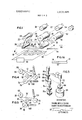
- FIG. I is a perspective view, partly schematic, of apparatus for imbibing or presoaking a length of mat film product of the Bimat type;
- FIG. 1A is a side elevational view of the presoaked mat film product having the protective cover film on the emulsion side thereof;
- FIG. 2 is a perspective view of the apparatus for utilizing the mat film product to develop a photographic negative film
- FIG. 3 is a schematic, perspective view of the drive means for the various spindles which mount the spools or reels for the mat product, the photographic negative film, and the protective cover film;
- FIGS. 4 and 5 are schematic views of the apparatus of FIG. 2 illustrating the way in which the protective cover film is removed from and again applied to the mat film product before and after the processing of the photographic negative film;
- FIG. 6 is a schematic view of apparatus utilizing the mat film product wherein the cover film remains with the mat and moves therewith into a processing spool;
- FIGS. 7A, 7B and 7C illustrate the way in which the mat and cover film of a mat film product are prepared for movement together into a processing spool in the manner shownin FIG. 6
- a mat film product of the Bimat type is broadly denoted by the numeral 10 and is shown in FIG. 1A as being comprised of a flexible backing strip or mat 12 having an emulsion on one face thereof and a flexible, protective cover film 14 in covering relationship to the emulsion side thereof.
- the product is provided with cover film 14 after it has been presoaked or imbibed with an imbibing solution, such imbibing step being required to place the emulsion on mat 12 in condition for processing a photographic film negative.
- Cover film 14 is used to protect the emulsion from deterioration due to contact with the air, so that product will have a relatively long shelf life.
- the apparatus of FIG. 1 illustrates how the imbibing step is accomplished and how cover film 14 is applied to mat 12 immediately after the emulsion is imbibed and before product 10 is used for developing a photographic negative film utilizing the apparatus of FIG. 2.
- the apparatus of FIG. 1 provides means for presoaking or imbibing the emulsion on mat 12 and includes a generally horizontal tank 18 provided with the imbibing solution to a predetermined level 20 therewithin.
- Spindles 22 and 24 disposed above the tank are mounted for rotation about generally horizontal axes, the spindles having reels or spools thereon whereby the mat 12 can be reeled in and out to facilitate movements through the solution.
- Bearings 26 and 28 mount spindles 22 and 24, respectively, and motors 30and 32 are utilized for selective rotation of respective spindles 22 and 24.
- Mat 12 is mounted for movement between spool 34 on spindle 22 and spool 36 on spindle 24.
- the mat travels beneath a pair of idler rollers 38 and 40 mounted on tank 18 at locations to position a horizontal stretch 42 of mat 12 below the level 20 of the imbibing solution.
- rollers 38 and 40 are mounted in bearings which allow them to be as free of frictional forces as possible.
- the imbibing solution is directed into and out of tank 18 through pipes 44 and 46.
- Tank 18 is provided with a heating and cooling unit 48 having a control 50 externally of the tank.
- Unit 48 is in heatexchange relationship to the imbibing solution so that selective control of the temperature of such solution can be achieved.
- Unit 48 may take the form of a single or composite unit which may be an electrical heating unit and an associated refrigeration coil or it may consist of thermoelectric cells capable of raising and lowering the solution temperature in proportion to the electrical input to unit 48.
- mat 12 is initially of the dry Kodak transfer film (Estar base) type SO-lll or SO-160. When properly soaked in the imbibing solution, such film is made ready for processing a photographic negative film. Presoaking apparatus other than that shown in FIG. 1 can be utilized, if desired.
- apparatus 16 is operated with the imbibing solution at an elevated temperature in the range between 90 and l l0 F. At this temperature, mat 12.is moved back and forth between reels 34'and 36 at speeds ranging from to 175 feet per minute. This movement between the reels is repeated a number of times until adequate absorption of the imbibing solution in the emulsion of the mat is accomplished.
- the temperature of the imbibing solution is lowered by unit 48 to a value approximately equal to the temperature at which the imbibed mat is to be stored.
- a hardener is added to the imbibing solution before the final pass and operates to harden the emulsion of mat 12 and to inhibit further absorption of the solution thereinto.
- the mat be transferred between reels 34 and 36 under conditions of minimum resistance so that the mat will be loosely coiled on the spools or reels.
- the soaking or absorption of the imbibing solution into the emulsion of mat 12 occurs mainly while the mat is wound on the reels and the passage of the mat between rollers 38 and 40 is mainly for the purpose of picking up the solution and carrying it out of tank 18 and intothe coil portions of the mat on the spools.
- the reels are preferably provided with sufficient resistance to provide a squeegee action to eliminate excess solution therefrom and minimize the presence of air pockets on the wound mat on takeup reel 36.
- tension will be applied to the mat and this tension can be achieved, for instance, by a brake mechanism (not shown) associated with motor of spindle 22.
- Apparatus 16 further includes a third spindle 52 coupled to a brake motor 54 and disposed for mounting a reel 56 containing a length of protective cover film 14.
- Film 14 is movable into covering relationshipto the emulsion side 58 of mat 12 in the final pass and as the mat moves into reel 36. Film 14 thus covers the emulsion side of mat 12 and protects the same while it is in the spool and prior to the use of the mat to develop a photographic film. Film 14 also minimizes or substantially eliminates any substantial deterioration of the presoaked emulsion of mat 12 during a relatively long storage time so that product 10 which is housed in spool 36 will have a relatively long shelf life.
- the imbibed mat filrn product 10, with the protective cover film thereon, is utilized with apparatus 58 shown in FIG. 2,
- spool 36 is mounted on a spindle 60 rotatably mounted on and projecting forwardly from the upper surface 62 of a boxlike base 64.
- Spindle 60 is operably coupled to a two-way or differential brake 66 disposed within base 64 to provide a certain amount of resistance to rotation for spindle 60 as product 10 is removed from spool 36.
- Base 64 is preferably of the type which forms one half of a lighttight housing wherein an upper half, shown in dashed lines in FIG. 2 and denoted by the numeral 68, is hollow and mates with the upper marginal extremity of base 64 to house spool 36 and the other structure mounted on surface 62 and hereinafter described. The reason for this is that an exposed photographic film can be reeled out from a reel or spool and into coupled relationship with mat film product 10 for processing without being exposed by undesirable radiation.
- Base 64 is provided with shaft means 70 and shaft means 72 parallel with spindle 60 and with each other.
- a reel or spool 74 is coupled with shaft means 70 and carries the photo graphic negative film 76 to be developed by mat film product 10.
- a takeup spool 78 is carried by shaft means 72 and has an opening (not shown) for 6 receiving product 10 and film 76 after protective cover film 14 has been removed from the emulsion side of product 10.
- third shaft means 80 is mounted for rotation on base 64 so that it projects upwardly from surface 62 and is spaced from spindle 60.
- a reel or spool 82 is mounted on shaft means 80 and receives protective cover film 14 as it emerges from spool 36. Cover film 14 is then wound onto reel 82 and remains thereon during the processing of film 76 by product 10 within spool 78.
- the means for rotating shaft means '70, 72 and 80 includes a motor 84 mounted within base 64 and connected. directly to shaft means 72.
- a handcrank 86 is operably coupled through a pair of beveled gears 88 and 90 in shaft means 72 for manually rotating the same if such is desired or deemed necessary.
- Shaft means 70 includes an upper shaft section 700, a lower shaft section 70b, and a slip clutch 98 between shaft sections 70a and 70b.
- shaft means 80 includes upper and lower shaft sections 80a and 80b and a slip clutch between the shaft sections.
- Shaft means 72 includes a single shaft.
- shaft means 72 The rotation of shaft means 72 is transferred to shaft means 70 by an endless, flexible belt 92 coupled to pulleys 94 and 96 on shaft means 72 and 70, respectively, pulley 96 being slightly larger than pulley 94 to provide a higher rotational speed for shaft means 70 relative to that for shaft means 72.
- This higher speed provides a resistance to the reel out of film 76 from reel 74 to thereby maintain tension on film 76 as it enters spool 78.
- Slip clutch 98 is used with shaft sections 70a and 70b to effect a braking action for reel 74 to maintain the above-mentioned tension onfilm 76.
- This braking action results because shaft section 70b rotates in a clockwise sense, when viewing FIG. 2 from the top, under the influence of belt 92; whereas, shaft section 70a tends to rotate in a counterclockwise sense under the influence of the reeling out of filrn 76 from reel 74 as film 76 enters spool 78.
- FIG. 3 shows how shaft means 80 is rotated to, in turn, cause rotation of reel 82 as cover film 14 emerges from spool 36.
- Lower shaft section 80b has a pulley 102 to which endless belt 92 is coupled.
- shaft 80b rotates with shaft 70b and v shaft means 72.
- shaft sections 80a and 80b rotate together and in the same direction.
- shaft sections 80a and 80b rotate in opposite directions as cover film 14 is again applied to mat 12 after the processing of film 76 in spool 78.
- a pressure roller 104 carried by a follower 106 is coupled to base 64 for movement toward and away from shaft 72.
- a suitable drive mechanism such as a bias spring or a piston and cylinder assembly (not shown), within base 64 is utilized to selectively move roller 104 toward and away from the entrance end of spool 78, whereby the emulsion side of mat 12 is forcibly pressed against film 76 as the two components enter spool 78.
- the processing of film 76 commences and the film and mat are developed together, the film being provided with a negative image and the mat being provided with a positive image.
- FIGS. 4 and 5 illustrate the operation of apparatus 58 and the way in which the method of this invention is carried out.
- spool 36 with the imbibed mat film product therein is placed on spindle 60. This is done either before or after the film reel or spool 74 is mounted on shaft means 70 and takeup spool 78 is mounted on shaft means 72.
- Product is manually reeled out a short distance from spool 36 so that the end of cover film 14 can'be coupled to reel 82 and mat 12 can be caused to enter spool 78 with film 76, the latter having been manually reeled out from reel 74 a short distance and directed into spool 78.
- a roller 104 is disposed adjacent to and movable toward and away from spool 78 and, as shown in FIG. 4, it is in close proximity to spool 78 so that it effectively forces mat 12 into mating engagement with film 76.
- cover film 14 is separated from mat 12 and moves onto reel 82.
- the motivating force for rotating reel 82 is preferably of the type shown in FIG. 3.
- film 76 is reeled out from reel 74 and mat 12 and film 76 continue to come into contact with each other as they enter the opening of spool 78 until all of the film 76 has been moved into spool 78 and all of cover film 14 is wound on reel 82.
- roller 108 Similar in all respects to roller 104 is provided and such roller is movable toward and away from shaft means 70 by any suitable structure, such as a piston and cylinder assembly.
- FIG. 4 illustrates that roller 108 is removed from shaft 70 so as not to interfere with the travel of film 76 to spool 78.
- cover film 14 As cover film 14 is reeled out from reel 82 (FIG. 5), it is subjected to tension. Thus, it mates cleanly with mat 12 to provide a neat appearance therefor. This tension results because the rotation of lower shaft section 80b is opposite to that of upper shaft section 80a due to slip clutch 100.
- spool 36 After mat 12 and cover film 14 enter and are housed in spool 36, the spool is ready for subsequent use and the resulttor for projection of the images thereon on a screen.
- Spools 36 and 78 could be in the form of open reels if desired.
- reels 74 and 82 could be spools. While the various shafts are shown as being substantially parallel with each other, they possibly could be angled relative to each other if suitable guides are used. This can be done without departing from the scope of the invention. Also, drive means other than that shown in the drawings can be used if such is deemed necessary or desirable.
- spool 82 is described above as being reversed on shaft to apply film 14 to the processed mat 12, it is possible to apply the cover film to the mat by providing a secondary motor to shaft 60 and necessary drive elements to allow directional reversal of all spools. This will avoid having to invert the spool and, if necessary, suitable guides can be provided to facilitate this step.
- cover film may be applied to the mat in the manner shown in FIG. 1, the present invention is not limited to this teaching, i.e., not limited to applying the cover film immediately after the imbibing step. It is possible to cover a previously packaged and properly stored roll of Bimat-type film after it has been presoaked. In such a case, the cover film is placed on the Bimat film and the latter is then repackaged properly. This procedure can be done with existing equipment, if desired.
- Cover film 14 will be transparent to allow the positive image on product 10 to be viewed, either directly or by projecting the image on a screen. While the processed mat product and the cover film may both be transparent to permit projecting of the image of the mat film product on a screen, it is possible that the cover film, 14 could be opaque so as to act as a reflection print. Additionally, if cover film 14 were transparent, use with the reflection'backed Bimat film would also provide for viewing by reflection. Reflection prints of this nature represent a typicalphotograph.
- the emulsion is tacky so as to form an adhesive surface.
- Cover film l4 adheres to this tacky surface and is removable therefrom by forcibly urging it away from such surface. Since cover film 14 can be applied once again to mat 12 after the processing step, substantial economies can be practiced since no additional cover film is required.
- a mat film product of the Bimat type broadly denoted by the numeral 110
- a flexible backing strip of mat 112 having an emulsion on one face thereof.
- a flexible, protective cover film 114 is disposed in covering relationship to the emulsion side of the mat with cover film 114 being applied to the mat after it has been presoaked or imbibed to place the emulsion of the mat in condition for processing a photographic negative film 120.
- Product is preferably wound on a spool or reel 116 with film 114 on the outer or emulsion side thereof as shown in FIG. 7A.
- One convolution of film 114 is unwound and severed to form the end shown in FIG. 78, this end and the outwardly projecting portion of mat 112 being in back-to-back relationship with respect to the emulsion side of the mat.
- the mat and cover film are then directed outwardly of and away from spool 116 and toward a processing spool 118, at which time, the mat and cover film are in back-to-back relationship as they enter and are wound ontospool 118.
- film 120 is moved away from supply spool 122, and enters spool 118 and engages the emulsion of mat 112.
- Pressure roller 124 assures good contact between mat 112 and film 120.
- cover film 114 is at all times out of contact with the emulsion sides of mat 112 and film 120.
- cover film 114 can be caused to pass over a dancer roller 126 to assure a predetermined tension thereon as they enter spool 118.
- the apparatus for accomplishing the steps described above may be of the type shown in F IG. 2 with the exception of spool 82 which is not needed.
- Spool 116 can be placed on shaft 70 and spool 122 can be placed on shaft 60. In this way, the apparatus is simplified and does not require special skills on the' part of the user of the apparatus.
- a method of handling a mat film product of the Bimat type comprising: moving the product through an imbibing solution to place the product in condition for processing a photographic negative film; applying a protective cover film to the emulsion side of the mat product after it has been imbibed; removing the cover film from said emulsion side; moving the product into engagement with a photographic negative film to be processed; separating the product from the photographic negative film after the latter has been processed; and applying said protective cover film to the emulsion side of the product after it has been separated from the photographic negative 2.
- a method of utilizing a mat film product of the Bimat type for processing a photographic negative film with the product having a protective film covering the emulsion side thereof comprising: moving the product along a predetermined path; removing the cover film from the emulsion side of the product as it moves along said path; moving the photographic negative film into engagement with said product after the cover film has been removed therefrom, whereby the photographic negative film will be processed by said product; separating the product from said photographic negative film after the latter has been processed; and applying said cover film to the emulsion side of the product after the latter has been separated from said photographic negative film.
- a method as set forth inclaim 2, wherein the step of moving the photographic negative film into engagement with the product includes winding the product and the negative film onto a roll and winding the cover film onto said roll after the cover film has been removed from the emulsion side of the product.
- step of separating the product from the negative film includes unwinding the product, the negative film and the cover film from the roll, said step of applying the cover film including'winding the product and the cover film on a second roll with the cover film on the emulsion side of the product.
- An apparatus for processing a photographic negative film using a Bimat-type film product having a protective cover film removably disposed on the emulsion side thereof comprising: a support; a spindle rotatably mounted on the support for mounting a reel containing said mat film product thereon; a
- first shaft spaced from said spindle and rotatably mounted on the support for mounting a reel having a photographic negative film thereon; a second shaft rotatably mounted on the support for positioning a takeup reel at a location permitting the mat film product and the photographic negative film to be wound thereon in mating relationship to each other; a third shaft mounted on said support in spaced relationshipto said first spindle for receiving a reel adapted to reel in the cover film removed from the mat film product as the latter moves to said takeup reel; means coupled with one of said shafts for rotating the same; and means coupled with the other of said shafts for rotating the same as a function of the rotation of said 7 one shaft.
- said means coupled with said one shaft comprises a motor, said means coupled with the other shafts including a belt and. pulley assembly interconnecting said shafts.
Landscapes
- Physics & Mathematics (AREA)
- General Physics & Mathematics (AREA)
- Engineering & Computer Science (AREA)
- Architecture (AREA)
- Structural Engineering (AREA)
- Photographic Developing Apparatuses (AREA)
- Photographic Processing Devices Using Wet Methods (AREA)
Abstract
A mat film product of the Bimat type wherein the product, after it has been presoaked or imbibed, is provided with a protective cover film on the emulsion side thereof. Apparatus for utilizing the imbibed product in the processing of photographic film includes structure permitting the removal of the cover film from the product immediately before it engages the photographic film to be processed yet allows the same cover film to be again applied to the product after the film processing step has been completed. The method of handling the product includes applying the cover film after imbibing the product, removing the cover film before processing the photographic film, and applying the cover film to the product after the film processing step.
Description
United States Patent [72] Inventors Franklin K. Chin;
Mt. View; Harry N. Diefienbach, Fremont, both of Calif. [21] Appl. No. 760,312 [22] Filed Sept. 17, 1968 [45] Patented Sept. 28, 1971 [73] Assignee Mark Systems, Inc.
Santa Clara, Calif.
[54] MAT FILM PRODUCT AND PROCESSING APPARATUS AND METHOD THEREFOR Primary Examiner-Samuel S. Matthews Assistant Examiner-Fred L. Braun Attorney-Townsend and Townsend ABSTRACT: A mat film product of the Bimat type wherein the product, after it has been presoaked or imbibed, is provided with a protective cover film on the emulsion side thereof. Apparatus for utilizing the imbibed product in the processing of photographic film includes structure permitting the removal of the cover film from the product immediately before it engages the photographic film to be processed yet allows the same cover film to be again applied to the product after the film processing step has been completed. The method of handling the product includes applying the cover film after imbibing the product, removing the cover film before processing the photographic film, and applying the cover film to the product after the film processing step.
PATENTEUsEP28mn 3,608,465
' SHEET 1 0F 3 FRANKLIN K.H.CH|NG HARRY N.D|EFFENBACH BY W b/QM ATTORNEYS PATENIED simian I 3,608,465
' sum 2 OF 3 INVENTORS FRANKLIN K.H.CH|NG HARRY N. DIEFFENBACH BY W ATTORNEYS PATENTEU SEP28 [9H 3,50 55 N sum 3 OF 3 INVENTORS FRANKLIN K.H.CH|NG HARRY N. DIEFFENBACH BY/ M Y/WMK ATTORNEYS MAT FILM PRODUCT AND PROCESSING APPARATUS AND METHOD THEREFOR This invention relates to Bimat-type film products and, more particularly, to such a mat film product having a protective cover film on the emulsion side thereof.
For processing photographic film, Eastman Kodak has developed a film process which uses a mat product known by its registered trademark as Bimat film wherein a mat carrying a photographic emulsion is, after first soaked in a developing solution, moved into mating engagement with an exposed photographic negativefilm. The emulsion side of ,the negative and the emulsion side of the mat contact each other when the two are forced together sothat development of both occurs simultaneously to cause the relatively unexposed parts of the negative to be transferred onto the mat and the relatively exposed parts of the negative to be retained thereon leaving a void on the mat. There is a graduation of the amount of the exposure transferred from the negative to the positive in proportion to the tone image characteristic of the contrast of standard photographic materials. After the development process, the mat and the negative are separated from each other, leaving the mat provided with a positive image of extremely fine resolution. Both the mat and the negative are then usually wound onto the separate spools or reels.
The present invention is directed to the preservation of the mat product before the actual processing of the negative film and after the mat product has been presoaked or imbibed. Generally, after the imbibing step, the mat product has a relatively short shelf life so that it must be usedsoon after it has The teachings of the present invention relate to a mat film product having a protective cover film on the emulsion side thereof with the cover film having been applied to the product immediately after it has been imbibed. Thus, the cover film will protect the emulsion and extend the shelf life of the mat.
product so as to avoid deterioration thereof for extended periods of time.
The present invention is further directed to apparatus for combining the imbibed mat product having the protective cover film thereon with a photographic negative to accomplish a development process of both the negative and the mat product whereby the mat product will be provided with a positive image. This apparatus includes a spindle for each of the supply spools or reels for the mat product and the photographic negative, a spindle for the takeup spool or reel which receives both the mat product and the photographic negative, and a spindle for a spool or reel which receives the protective cover film as the latter is separated from the mat product immediately before the latter enters the takeup reel with the photographic negative. Pressure roller means is utilized to force the mat product and the photographic negative into juxtaposition with each other so that there will be sufficient contact to effect the processing step.
The same apparatus can be 'used to separate the mat product from the photographic negative after the processing step and to apply the protective cover film once again to the emulsion side of the processed mat product. Thus, the same cover film serves to protect the emulsion side of the mat product before and after the processing step. Thus, the mat product can be safely handled without loss of or damage to the emulsion thereon.
The primary object of this invention is to provide an improved photographic product of the Bimat type wherein the product has a protective cover film on its emulsion side after it has been presoaked or imbibed so as to extend the shelf life of the product as well as to protect its emulsion prior to and after using the product for processing a photographic negative.
Another object of this invention is to provide apparatus and a method for use in processing a photographic negative with a mat film product of the type described wherein the protective cover film is separated from the mat product before the processing step is commenced and is again applied to the mat product after the processing step to provide for minimum exposure of the emulsion side of the mat product to the deteriorating effects of the atmosphere while permitting the cover film to be used again after the processing step for purposes of economy.
Still another object of this invention is to provide apparatus and a method of the aforesaid character which permits the use of a mat film product of the Bimat type at a relatively long time" after it has been presoaked or imbibed so that the product can be stored in its imbibed condition and is suitable for field use where imbibing equipment is not available or can not be conveniently made available.
The mat product of this invention can also be utilized without fully' separating the cover film from the mat itselffTo accomplish this, the protective cover film is separated from the emulsion side of the mat and directed therewith in backto-back relationship into the processing spool within which a photographic negative film is processed by the mat. When the processing step is completed, the cover film emerges from the processing spool with the mat and is automatically moved once again onto the emulsion side of the mat as the latter and the cover film are wound on a takeup reel or spool. In this way, conventional processing apparatus used with Bimat-type film can be used with the mat film product of this invention.
Thus, it is another object of this invention to provide a mat film product of the type described and a method of using the same wherein the protective cover film on the mat can be removed from the emulsion side thereof and caused'to move with the mat into and out of a processing spool whereby a photographic film can be processed by the mat even though the cover film is within the processing spool and the emulsion side of the mat can automatically be covered by the cover film as the mat and cover film are removed from the processing spool and are wound on a takeup spool.
Other objects of this invention will become apparent as the following specification progresses, reference being had to the accompanying drawings for an illustration of the mat film product and the apparatus used to carry out the method of handling the product.
In the drawings:
FIG. I is a perspective view, partly schematic, of apparatus for imbibing or presoaking a length of mat film product of the Bimat type;
FIG. 1A is a side elevational view of the presoaked mat film product having the protective cover film on the emulsion side thereof;
FIG. 2 is a perspective view of the apparatus for utilizing the mat film product to develop a photographic negative film;
FIG. 3 is a schematic, perspective view of the drive means for the various spindles which mount the spools or reels for the mat product, the photographic negative film, and the protective cover film;
FIGS. 4 and 5 are schematic views of the apparatus of FIG. 2 illustrating the way in which the protective cover film is removed from and again applied to the mat film product before and after the processing of the photographic negative film;
FIG. 6 is a schematic view of apparatus utilizing the mat film product wherein the cover film remains with the mat and moves therewith into a processing spool; and
FIGS. 7A, 7B and 7C illustrate the way in which the mat and cover film of a mat film product are prepared for movement together into a processing spool in the manner shownin FIG. 6
A mat film product of the Bimat type is broadly denoted by the numeral 10 and is shown in FIG. 1A as being comprised of a flexible backing strip or mat 12 having an emulsion on one face thereof and a flexible, protective cover film 14 in covering relationship to the emulsion side thereof. The product is provided with cover film 14 after it has been presoaked or imbibed with an imbibing solution, such imbibing step being required to place the emulsion on mat 12 in condition for processing a photographic film negative. Cover film 14 is used to protect the emulsion from deterioration due to contact with the air, so that product will have a relatively long shelf life. The apparatus of FIG. 1 illustrates how the imbibing step is accomplished and how cover film 14 is applied to mat 12 immediately after the emulsion is imbibed and before product 10 is used for developing a photographic negative film utilizing the apparatus of FIG. 2.
The apparatus of FIG. 1 provides means for presoaking or imbibing the emulsion on mat 12 and includes a generally horizontal tank 18 provided with the imbibing solution to a predetermined level 20 therewithin. Spindles 22 and 24 disposed above the tank are mounted for rotation about generally horizontal axes, the spindles having reels or spools thereon whereby the mat 12 can be reeled in and out to facilitate movements through the solution. Bearings 26 and 28 mount spindles 22 and 24, respectively, and motors 30and 32 are utilized for selective rotation of respective spindles 22 and 24.
Mat 12 is mounted for movement between spool 34 on spindle 22 and spool 36 on spindle 24. The mat travels beneath a pair of idler rollers 38 and 40 mounted on tank 18 at locations to position a horizontal stretch 42 of mat 12 below the level 20 of the imbibing solution. Preferably, rollers 38 and 40 are mounted in bearings which allow them to be as free of frictional forces as possible. The imbibing solution is directed into and out of tank 18 through pipes 44 and 46.
Tank 18 is provided with a heating and cooling unit 48 having a control 50 externally of the tank. Unit 48 is in heatexchange relationship to the imbibing solution so that selective control of the temperature of such solution can be achieved. Unit 48 may take the form of a single or composite unit which may be an electrical heating unit and an associated refrigeration coil or it may consist of thermoelectric cells capable of raising and lowering the solution temperature in proportion to the electrical input to unit 48. For purposes of illustration, mat 12 is initially of the dry Kodak transfer film (Estar base) type SO-lll or SO-160. When properly soaked in the imbibing solution, such film is made ready for processing a photographic negative film. Presoaking apparatus other than that shown in FIG. 1 can be utilized, if desired.
For purposes of illustration, apparatus 16 is operated with the imbibing solution at an elevated temperature in the range between 90 and l l0 F. At this temperature, mat 12.is moved back and forth between reels 34'and 36 at speeds ranging from to 175 feet per minute. This movement between the reels is repeated a number of times until adequate absorption of the imbibing solution in the emulsion of the mat is accomplished. For the final pass of mat 12 through the solution, the temperature of the imbibing solution is lowered by unit 48 to a value approximately equal to the temperature at which the imbibed mat is to be stored. A hardener is added to the imbibing solution before the final pass and operates to harden the emulsion of mat 12 and to inhibit further absorption of the solution thereinto.
It is preferable that, except for the pass, the mat be transferred between reels 34 and 36 under conditions of minimum resistance so that the mat will be loosely coiled on the spools or reels. Thus, the soaking or absorption of the imbibing solution into the emulsion of mat 12 occurs mainly while the mat is wound on the reels and the passage of the mat between rollers 38 and 40 is mainly for the purpose of picking up the solution and carrying it out of tank 18 and intothe coil portions of the mat on the spools. Also, during the final pass, the reels are preferably provided with sufficient resistance to provide a squeegee action to eliminate excess solution therefrom and minimize the presence of air pockets on the wound mat on takeup reel 36. Thus, tension will be applied to the mat and this tension can be achieved, for instance, by a brake mechanism (not shown) associated with motor of spindle 22.
The imbibed mat filrn product 10, with the protective cover film thereon, is utilized with apparatus 58 shown in FIG. 2,
wherein spool 36 is mounted on a spindle 60 rotatably mounted on and projecting forwardly from the upper surface 62 of a boxlike base 64. Spindle 60 is operably coupled to a two-way or differential brake 66 disposed within base 64 to provide a certain amount of resistance to rotation for spindle 60 as product 10 is removed from spool 36. Base 64 is preferably of the type which forms one half of a lighttight housing wherein an upper half, shown in dashed lines in FIG. 2 and denoted by the numeral 68, is hollow and mates with the upper marginal extremity of base 64 to house spool 36 and the other structure mounted on surface 62 and hereinafter described. The reason for this is that an exposed photographic film can be reeled out from a reel or spool and into coupled relationship with mat film product 10 for processing without being exposed by undesirable radiation.
The means for rotating shaft means '70, 72 and 80 includes a motor 84 mounted within base 64 and connected. directly to shaft means 72. A handcrank 86 is operably coupled through a pair of beveled gears 88 and 90 in shaft means 72 for manually rotating the same if such is desired or deemed necessary.
Shaft means 70 includes an upper shaft section 700, a lower shaft section 70b, and a slip clutch 98 between shaft sections 70a and 70b. Similarly, shaft means 80 includes upper and lower shaft sections 80a and 80b and a slip clutch between the shaft sections. Shaft means 72 includes a single shaft.
The rotation of shaft means 72 is transferred to shaft means 70 by an endless, flexible belt 92 coupled to pulleys 94 and 96 on shaft means 72 and 70, respectively, pulley 96 being slightly larger than pulley 94 to provide a higher rotational speed for shaft means 70 relative to that for shaft means 72. This higher speed provides a resistance to the reel out of film 76 from reel 74 to thereby maintain tension on film 76 as it enters spool 78.
Slip clutch 98 is used with shaft sections 70a and 70b to effect a braking action for reel 74 to maintain the above-mentioned tension onfilm 76. This braking action results because shaft section 70b rotates in a clockwise sense, when viewing FIG. 2 from the top, under the influence of belt 92; whereas, shaft section 70a tends to rotate in a counterclockwise sense under the influence of the reeling out of filrn 76 from reel 74 as film 76 enters spool 78.
FIG. 3 shows how shaft means 80 is rotated to, in turn, cause rotation of reel 82 as cover film 14 emerges from spool 36. Lower shaft section 80b has a pulley 102 to which endless belt 92 is coupled. Thus, shaft 80b rotates with shaft 70b and v shaft means 72. As cover film l4 emerges from spool 36, shaft sections 80a and 80b rotate together and in the same direction. As will hereinafter be set forth, shaft sections 80a and 80b rotate in opposite directions as cover film 14 is again applied to mat 12 after the processing of film 76 in spool 78.
To assure that mat 12 and film 76 move into substantial contact with each other, a pressure roller 104 carried by a follower 106 is coupled to base 64 for movement toward and away from shaft 72. A suitable drive mechanism, such as a bias spring or a piston and cylinder assembly (not shown), within base 64 is utilized to selectively move roller 104 toward and away from the entrance end of spool 78, whereby the emulsion side of mat 12 is forcibly pressed against film 76 as the two components enter spool 78. When this occurs, the processing of film 76 commences and the film and mat are developed together, the film being provided with a negative image and the mat being provided with a positive image.
FIGS. 4 and 5 illustrate the operation of apparatus 58 and the way in which the method of this invention is carried out.
Initially, spool 36 with the imbibed mat film product therein is placed on spindle 60. This is done either before or after the film reel or spool 74 is mounted on shaft means 70 and takeup spool 78 is mounted on shaft means 72. Product is manually reeled out a short distance from spool 36 so that the end of cover film 14 can'be coupled to reel 82 and mat 12 can be caused to enter spool 78 with film 76, the latter having been manually reeled out from reel 74 a short distance and directed into spool 78. A roller 104 is disposed adjacent to and movable toward and away from spool 78 and, as shown in FIG. 4, it is in close proximity to spool 78 so that it effectively forces mat 12 into mating engagement with film 76.
As product 10 emerges from spool 36 and travels toward spool 78, cover film 14 is separated from mat 12 and moves onto reel 82. The motivating force for rotating reel 82 is preferably of the type shown in FIG. 3. Simultaneously, film 76 is reeled out from reel 74 and mat 12 and film 76 continue to come into contact with each other as they enter the opening of spool 78 until all of the film 76 has been moved into spool 78 and all of cover film 14 is wound on reel 82.
After mat 12 and film 76 have been in contact .with each other for the required processing time, they are removed from spool 78 and are separated from each other, the mat being returned to spool 36 while the film is returned to reel 74. To
effect this operation, spool 78 is removed from shaft means 72,
and placed on spindle 60, whereupon reel 74 is placed on shaft 72 and spool 36 is placed on shaft means 70 for receiving the mat 12 once again.
As mat 12 and film 76 emerge from spool 78, mat 12 travels to spool 36 and film 76 travels to spool 74 (FIG. 5). The movements of shaft means 70 and 72 to rotate respective reels 36 and 74 is accomplished either by motor 84 or by handcrank 86. Also, reel 82, which will previously have been inverted, is rotated to permit reeling out of cover film 14 which also enters spool 36 and simultaneously moves into intimate contact with and covers the emulsion side of mat 12. Cover film 14 adheres to mat 12 because of the tacky character of the emulsion on the mat. Thus, the mat and cover film once again form a unitary construction in the manner shown in FIG. 1A. To facilitate the intimate contact between mat 12 and cover film 14, another pressure roller 108 similar in all respects to roller 104 is provided and such roller is movable toward and away from shaft means 70 by any suitable structure, such as a piston and cylinder assembly. FIG. 4 illustrates that roller 108 is removed from shaft 70 so as not to interfere with the travel of film 76 to spool 78.
As cover film 14 is reeled out from reel 82 (FIG. 5), it is subjected to tension. Thus, it mates cleanly with mat 12 to provide a neat appearance therefor. This tension results because the rotation of lower shaft section 80b is opposite to that of upper shaft section 80a due to slip clutch 100.
After mat 12 and cover film 14 enter and are housed in spool 36, the spool is ready for subsequent use and the resulttor for projection of the images thereon on a screen.
While spool 82 is described above as being reversed on shaft to apply film 14 to the processed mat 12, it is possible to apply the cover film to the mat by providing a secondary motor to shaft 60 and necessary drive elements to allow directional reversal of all spools. This will avoid having to invert the spool and, if necessary, suitable guides can be provided to facilitate this step.
While the cover film may be applied to the mat in the manner shown in FIG. 1, the present invention is not limited to this teaching, i.e., not limited to applying the cover film immediately after the imbibing step. It is possible to cover a previously packaged and properly stored roll of Bimat-type film after it has been presoaked. In such a case, the cover film is placed on the Bimat film and the latter is then repackaged properly. This procedure can be done with existing equipment, if desired.
. Cover film 14 will be transparent to allow the positive image on product 10 to be viewed, either directly or by projecting the image on a screen. While the processed mat product and the cover film may both be transparent to permit projecting of the image of the mat film product on a screen, it is possible that the cover film, 14 could be opaque so as to act as a reflection print. Additionally, if cover film 14 were transparent, use with the reflection'backed Bimat film would also provide for viewing by reflection. Reflection prints of this nature represent a typicalphotograph.
After the imbibing step, the emulsion is tacky so as to form an adhesive surface. Cover film l4 adheres to this tacky surface and is removable therefrom by forcibly urging it away from such surface. Since cover film 14 can be applied once again to mat 12 after the processing step, substantial economies can be practiced since no additional cover film is required.
The teachingsof the invention can also be utilized in the manner shown in FIGS. 6, 7A, 7B and 7C wherein a mat film product of the Bimat type, broadly denoted by the numeral 110, includes a flexible backing strip of mat 112 having an emulsion on one face thereof. A flexible, protective cover film 114 is disposed in covering relationship to the emulsion side of the mat with cover film 114 being applied to the mat after it has been presoaked or imbibed to place the emulsion of the mat in condition for processing a photographic negative film 120.
Product is preferably wound on a spool or reel 116 with film 114 on the outer or emulsion side thereof as shown in FIG. 7A. One convolution of film 114 is unwound and severed to form the end shown in FIG. 78, this end and the outwardly projecting portion of mat 112 being in back-to-back relationship with respect to the emulsion side of the mat. The mat and cover film are then directed outwardly of and away from spool 116 and toward a processing spool 118, at which time, the mat and cover film are in back-to-back relationship as they enter and are wound ontospool 118. Simultaneously with this action, film 120 is moved away from supply spool 122, and enters spool 118 and engages the emulsion of mat 112. Pressure roller 124 assures good contact between mat 112 and film 120. While in spool 118, cover film 114 is at all times out of contact with the emulsion sides of mat 112 and film 120. Mat
112 and cover film 114 can be caused to pass over a dancer roller 126 to assure a predetermined tension thereon as they enter spool 118.
In moving out of spool 118, photographic film 120 will again pass toward and into spool 122, whereas mat 112 and cover film 114 will move toward and enter spool 116. Film 114 will automatically move onto the emulsion side of film 112 so that, when completely wound on the spool 116, only one convolution of mat 112 will not have film 114 applied to the emulsion thereon. This end portion generally will have no usable image on it and, if it does have an image, it can be covered by an additional length of cover film 114.
The apparatus for accomplishing the steps described above may be of the type shown in F IG. 2 with the exception of spool 82 which is not needed. Spool 116 can be placed on shaft 70 and spool 122 can be placed on shaft 60. In this way, the apparatus is simplified and does not require special skills on the' part of the user of the apparatus.
We claim:
1. A method of handling a mat film product of the Bimat type comprising: moving the product through an imbibing solution to place the product in condition for processing a photographic negative film; applying a protective cover film to the emulsion side of the mat product after it has been imbibed; removing the cover film from said emulsion side; moving the product into engagement with a photographic negative film to be processed; separating the product from the photographic negative film after the latter has been processed; and applying said protective cover film to the emulsion side of the product after it has been separated from the photographic negative 2. A method of utilizing a mat film product of the Bimat type for processing a photographic negative film with the product having a protective film covering the emulsion side thereof comprising: moving the product along a predetermined path; removing the cover film from the emulsion side of the product as it moves along said path; moving the photographic negative film into engagement with said product after the cover film has been removed therefrom, whereby the photographic negative film will be processed by said product; separating the product from said photographic negative film after the latter has been processed; and applying said cover film to the emulsion side of the product after the latter has been separated from said photographic negative film.
3. A method as set forth inclaim 2, wherein the step of moving the photographic negative film into engagement with the product includes winding the product and the negative film onto a roll and winding the cover film onto said roll after the cover film has been removed from the emulsion side of the product.
4. 'A method as set forth in claim 3, wherein said step of separating the product from the negative film includes unwinding the product, the negative film and the cover film from the roll, said step of applying the cover film including'winding the product and the cover film on a second roll with the cover film on the emulsion side of the product.
5. An apparatus for processing a photographic negative film using a Bimat-type film product having a protective cover film removably disposed on the emulsion side thereof comprising: a support; a spindle rotatably mounted on the support for mounting a reel containing said mat film product thereon; a
first shaft spaced from said spindle and rotatably mounted on the support for mounting a reel having a photographic negative film thereon; a second shaft rotatably mounted on the support for positioning a takeup reel at a location permitting the mat film product and the photographic negative film to be wound thereon in mating relationship to each other; a third shaft mounted on said support in spaced relationshipto said first spindle for receiving a reel adapted to reel in the cover film removed from the mat film product as the latter moves to said takeup reel; means coupled with one of said shafts for rotating the same; and means coupled with the other of said shafts for rotating the same as a function of the rotation of said 7 one shaft.
6. An apparatus as set forth'in claim 5, wherein said means coupled with said one shaft comprises a motor, said means coupled with the other shafts including a belt and. pulley assembly interconnecting said shafts.
Claims (5)
- 2. A method of utilizing a mat film product of the Bimat type for processing a photographic negative film with the product having a protective film covering the emulsion side thereof comprising: moving the product along a predetermined path; removing the cover film from the emulsion side of the product as it moves along said path; moving the photographic negative film into engagement with said product after the cover film has been removed therefrom, whereby the photographic negative film will be processed by said product; separating the product from said photographic negative film after the latter has been processed; and applying said cover film to the emulsion side of the product after the latter has been separated from said photographic negative film.
- 3. A method as set forth in claim 2, wherein the step of moving the photographic negative film into engagement with the product includes winding the product and the negative film onto a roll and winding the cover film onto said roll after the cover film has been removed from the emulsion side of the product.
- 4. A method as set forth in claim 3, wherein said step of separating the product from the negative film includes unwinding the product, the negative film and the cover film from the roll, said step of applying the cover film including winding the product and the cover film on a second roll with the cover film on the emulsion side of the product.
- 5. An apparatus for processing a photographic negative film using a Bimat-type film product having a protective cover film removably disposed on the emulsion side thereof comprising: a support; a spindle rotatably mounted on the support for mounting a reel containing said mat film product thereon; a first shaft spaced from said spindle and rotatably mounted on the support for mounting a reel having a photographic negative film thereon; a second shaft rotatably mounted on the support for positioning a takeup reel at a location permitting the mat film product and the photographic negative film to be wound thereon in mating relationship to each other; a third shaft mounted on said support in spaced relationship to said first spindle for receiving a reel adapted to reel in the cover film removed from the mat film product as the latter moves to said takeup reel; means coupled with one of said shafts for rotating the same; and means coupled with the other of said shafts for rotating the same as a function of the rotation of said one shaft.
- 6. An apparatus as set forth in claim 5, wherein said means coupled with said one shaft comprises a motor, said means coupled with the other shafts including a belt and pulley assembly interconnecting said shafts.
Applications Claiming Priority (1)
| Application Number | Priority Date | Filing Date | Title |
|---|---|---|---|
| US76031268A | 1968-09-17 | 1968-09-17 |
Publications (1)
| Publication Number | Publication Date |
|---|---|
| US3608465A true US3608465A (en) | 1971-09-28 |
Family
ID=25058724
Family Applications (1)
| Application Number | Title | Priority Date | Filing Date |
|---|---|---|---|
| US760312A Expired - Lifetime US3608465A (en) | 1968-09-17 | 1968-09-17 | Mat film product and processing apparatus and method therefor |
Country Status (2)
| Country | Link |
|---|---|
| US (1) | US3608465A (en) |
| DE (1) | DE1946308A1 (en) |
Cited By (1)
| Publication number | Priority date | Publication date | Assignee | Title |
|---|---|---|---|---|
| US4325624A (en) * | 1980-09-02 | 1982-04-20 | Polaroid Corporation | Self-developing type film processor kit |
Citations (4)
| Publication number | Priority date | Publication date | Assignee | Title |
|---|---|---|---|---|
| US2572357A (en) * | 1945-07-13 | 1951-10-23 | Polaroid Corp | Photographic product comprising a fluid processing agent and apparatus for use in connection therewith |
| US3179517A (en) * | 1959-08-24 | 1965-04-20 | Eastman Kodak Co | Web processing method and composition |
| US3334565A (en) * | 1964-09-18 | 1967-08-08 | Mark Systems Inc | Combination film processing drier viewer |
| US3413181A (en) * | 1963-11-26 | 1968-11-26 | Chicago Aerial Ind Inc | Photographic processing web material |
-
1968
- 1968-09-17 US US760312A patent/US3608465A/en not_active Expired - Lifetime
-
1969
- 1969-09-12 DE DE19691946308 patent/DE1946308A1/en active Pending
Patent Citations (4)
| Publication number | Priority date | Publication date | Assignee | Title |
|---|---|---|---|---|
| US2572357A (en) * | 1945-07-13 | 1951-10-23 | Polaroid Corp | Photographic product comprising a fluid processing agent and apparatus for use in connection therewith |
| US3179517A (en) * | 1959-08-24 | 1965-04-20 | Eastman Kodak Co | Web processing method and composition |
| US3413181A (en) * | 1963-11-26 | 1968-11-26 | Chicago Aerial Ind Inc | Photographic processing web material |
| US3334565A (en) * | 1964-09-18 | 1967-08-08 | Mark Systems Inc | Combination film processing drier viewer |
Cited By (1)
| Publication number | Priority date | Publication date | Assignee | Title |
|---|---|---|---|---|
| US4325624A (en) * | 1980-09-02 | 1982-04-20 | Polaroid Corporation | Self-developing type film processor kit |
Also Published As
| Publication number | Publication date |
|---|---|
| DE1946308A1 (en) | 1970-04-02 |
Similar Documents
| Publication | Publication Date | Title |
|---|---|---|
| US2435718A (en) | Photographic process and apparatus for subjecting a photographic film to a processing fluid | |
| US4309100A (en) | Film processor for instant type transparency film | |
| US4370045A (en) | Film processor | |
| US3641896A (en) | Motion picture film cassette-processor system | |
| US3623417A (en) | System for uniformly coating exposed motion picture film with processing fluid | |
| US3640204A (en) | Photographic web processing device | |
| GB997967A (en) | Improvements in or relating to photographic type composing devices and a method of photographically composing type images | |
| US3912833A (en) | Film processing apparatus and method for information storage system | |
| US4408872A (en) | Combined storing, transporting, exposing and processing apparatus for camera | |
| US3608465A (en) | Mat film product and processing apparatus and method therefor | |
| US3910698A (en) | Photographic apparatus | |
| US3547535A (en) | Microfilm document copier | |
| US4013360A (en) | Information storage system | |
| US4566772A (en) | Film processor for premounted transparency frames | |
| US3380679A (en) | Mat processor | |
| US4313667A (en) | Film processor having automatically actuated film severing means | |
| US3264962A (en) | Removable film process magazine | |
| US4593867A (en) | Film storage device in camera processor | |
| US2455125A (en) | Apparatus for exposing and processing photographic film | |
| US2220917A (en) | Camera | |
| US3256794A (en) | Photomechanical camera with plurality of film holders | |
| US3711192A (en) | Motion picture cassette | |
| US4568163A (en) | Camera back | |
| US3655277A (en) | Motion-picture system | |
| US3537784A (en) | Motion picture processing and projection system employing multipurpose cassette and strip tape |