US5875209A - Digital radio system including repeater equipment, end equipment and receiver - Google Patents
Digital radio system including repeater equipment, end equipment and receiver Download PDFInfo
- Publication number
- US5875209A US5875209A US08/629,389 US62938996A US5875209A US 5875209 A US5875209 A US 5875209A US 62938996 A US62938996 A US 62938996A US 5875209 A US5875209 A US 5875209A
- Authority
- US
- United States
- Prior art keywords
- intersymbol interference
- information
- frequency
- degree
- pairs
- Prior art date
- Legal status (The legal status is an assumption and is not a legal conclusion. Google has not performed a legal analysis and makes no representation as to the accuracy of the status listed.)
- Expired - Fee Related
Links
Images


Classifications
-
- H—ELECTRICITY
- H04—ELECTRIC COMMUNICATION TECHNIQUE
- H04B—TRANSMISSION
- H04B7/00—Radio transmission systems, i.e. using radiation field
- H04B7/14—Relay systems
- H04B7/15—Active relay systems
- H04B7/155—Ground-based stations
- H04B7/15528—Control of operation parameters of a relay station to exploit the physical medium
- H04B7/15542—Selecting at relay station its transmit and receive resources
Definitions
- the present invention relates to a digital radio system which forms a high speed digital radio transmission line through a plurality of repeater offices positioned within line-of-sight distances using a microwave band radio frequency, more particularly relates to repeater equipment and end equipment respectively constituting a repeater office and end office in that system and to a receiver mounted in that equipment.
- the present invention has as its object the provision of a digital radio system including repeater equipment, end equipment, and a receiver which enables early and reliable detection of the occurrence of a notch at each repeater section and efficient maintenance of transmission quality.
- the present invention provides a digital radio system including repeater equipment provided with a plurality of pairs of regenerating devices between the transmitting and receiving ends for individually receiving waves of upstream and downstream routes at repeating points of redundantly configured radio transmission lines formed under a full duplex mode and demultiplexing and extracting the transmission information and control information multiplexed in the received waves, a plurality of pairs of repeating units for multiplexing the transmission information and control information individually extracted by the plurality of pairs of regenerating units and relaying them to the following repeater sections through the redundantly configured radio transmission lines, and a plurality of intersymbol interference measuring means for individually measuring the degree or frequency of intersymbol interference of received waves for one of the upstream and downstream routes, the repeating means corresponding to the one upstream or downstream route among the plurality of pairs of repeating units further including a multiplexing unit for multiplexing the transmission information and control information individually extracted by the regenerating units corresponding to that one route among the plurality of pairs of regenerating units together with information indicative
- FIG. 1 is a block diagram of the principle of the invention according to the first to sixth aspects and the tenth aspect;
- FIG. 2 is a block diagram of the principle of the invention according to the seventh aspect
- FIG. 3 is a block diagram of the principle of the invention according to the eighth aspect.
- FIG. 4 is a block diagram of the principle of the invention according to the ninth aspect.
- FIG. 5 is a view of an embodiment of the invention according to the first to fifth aspects, and the seventh and the tenth aspects;
- FIGS. 6A and 6B are views explaining the configuration and operation of an intersymbol interference detecting unit
- FIG. 7 is a view of the operation of the embodiment of the invention.
- FIGS. 8A and 8 are views of the frame format of the embodiment of the invention.
- FIG. 9 is a view explaining the operation of an embodiment of the invention according to the first aspect.
- FIG. 10 is a view of an embodiment of the invention according to the eighth aspect.
- FIG. 11 is a view of an embodiment of the invention according to the ninth aspect.
- FIGS. 12A and 12B are views of an embodiment of the invention according to the tenth aspect
- FIGS. 13A and 13B are views of a first modification of the embodiment shown in FIGS. 12A and 12B;
- FIGS. 14A and 14B are views of a second modification of the embodiment shown in FIGS. 12A and 12B;
- FIGS. 15A to 15F are views explaining specific examples of the adding/selecting unit shown in FIG. 5;
- FIG. 16 is a view of an example of the configuration of a conventional digital radio system
- FIG. 17 is a view explaining the cause of occurrence of a notch
- FIG. 18 is a view explaining fluctuations in the receiving power caused by a notch
- FIG. 19 is a view showing fluctuations in the bit error rate in terms of an eye aperture.
- FIG. 20 is a view showing changes in the signature along with notch growth.
- FIG. 16 is a view of an example of the configuration of a conventional digital radio system.
- the end offices 121 S and 121 R are arranged at the two ends of a plurality (herein, for simplification, the sum of three working lines and one standby line using N+ one protection system) of radio transmission lines.
- three repeater offices 122 1 to 122 3 are arranged on these three radio transmission lines.
- these radio transmission lines are each comprised of full duplex lines.
- the upstream transmission line extending from the end office 121 S to the end office 121 R .
- the opposite downstream transmission line is shown by the box shown by the dotted lines. Illustration of the detailed configuration is omitted.
- the radio transmission lines of the sections (hop) between the end office and the adjoining repeater office and between two adjoining repeater offices are formed under regenerative repeat operations conducted by the repeater offices 122 1 to 122 3 at all times. Further, on these radio transmission lines, as shown in FIG. 17, a direct wave which directly reaches the receiving antenna of an office from the antenna of an opposing office over a line-of-sight distance, a reflected wave arriving reflected from the ground etc. of the corresponding section, and a refracted wave occur.
- the levels of the received fields and the phases of the direct wave, reflected wave, and refracted wave change governed by the characteristics of reflection from the ground surface etc. and the meteorological conditions in the corresponding section and so on, so the received wave, which is obtained as the vector sum of the reflected wave and direct wave, is accompanied by frequency-selective fading (hereinafter referred to as a "notch"), as shown, for example, in FIG. 18.
- a notch frequency-selective fading
- the end office 121 R acting as the receiving end performs processing to receive signals and processing to reproduce the transmission information for the individual radio transmission lines and judges the relative magnitude between the bit error rate of the transmission information (here, for simplification, considered obtained based on the true or false logic of the parity bit added to the transmission information) and a predetermined threshold.
- this threshold as shown in FIG. 19, is set to "10 -5 " to "10 -4 ".
- the end office 121 R when the end office 121 R recognizes that the bit error rate has exceeded the above threshold, it sends that fact and identification information of the corresponding radio transmission line (hereinafter referred to as a "request for parallel connecting transmission") to specific predetermined downstream radio transmission lines serving for maintenance and operational use (hereinafter referred to simply as a “control use transmission line”).
- a request for parallel connecting transmission that fact and identification information of the corresponding radio transmission line
- specific predetermined downstream radio transmission lines serving for maintenance and operational use hereinafter referred to simply as a "control use transmission line”
- This request for parallel connecting transmission is constantly watched for by the end office 121 S acting as the transmitting end of the upstream radio transmission line.
- the end office takes the radio transmission line set for standby use and sends the transmission information to be sent over the working radio transmission line through both the above standby use radio transmission line and the working radio transmission line, shown by the identification information included in the request for parallel connecting transmission.
- This sending of transmission information is referred to as the "parallel connecting transmission”.
- the end office 121 R acting as the receiving end performs processing adapted to the method of transmission of the radio transmission line on the transmission information obtained from the standby radio transmission line under this parallel connecting transmission so as to minimize the phase difference between the transmission information obtained from the working radio transmission line and the transmission information obtained from the standby radio transmission line, and changes from the working radio transmission line to the standby radio transmission line are uninterrupted so as to avoid any deterioration of the transmission quality caused by the occurrence of the notch.
- bit error rate BER at the receiving end is generally expressed as
- trials at parallel connecting transmission are started after the elapse of a long period of at least several tens of milliseconds from the time of occurrence of a notch, so in many cases a large amount of transmission information is sent over the working radio transmission line with a deteriorated transmission quality before the parallel connecting transmission and the quality of the transmission temporarily becomes extremely poor.
- bit error rate when the bit error rate is fixed to 10 -5 , double the 29.4 msec of time is necessary for detection, but the actual bit error rate rapidly deteriorates, so the detection time is greatly reduced.
- the signature generally changes most rapidly as shown by the arrows A and B in FIG. 20 when the notch moves at a high speed on the frequency axis.
- the present invention provides a digital radio system including repeater equipment, end equipment, and a receiver which enables early and reliable detection of the occurrence of notches at each repeater section and efficient maintenance of transmission quality.
- FIG. 1 is a block diagram of the principle of the invention according to the first to sixth aspects and the tenth aspect.
- the invention provides repeater equipment provided with a plurality of pairs of regenerating means 11 11 , 11 12 to 11 N1 , 11 N2 between transmitting and receiving ends for individually receiving waves of upstream and downstream routes of the radio transmission lines at repeating points of redundantly configured radio transmission lines formed under a full duplex mode and demultiplexing and extracting the transmission information and control information multiplexed in the received waves; a plurality of pairs of repeating means 13 11 , 13 12 to 13 N1 , 13 N2 for multiplexing the transmission information and control information individually extracted by the plurality of pairs of regenerating means 11 11 , 11 12 to 11 N1 , 11 N2 and relaying them to the following repeater sections through the redundantly configured radio transmission lines; and a plurality of intersymbol interference measuring means 15 1 to 15 N for individually monitoring the increment and decrement in the eye apertures of the received waves and measuring the degree or frequency of intersymbol interference for one of the upstream and downstream routes of the redundantly configured radio transmission lines; the repeating
- the regenerating means 11 11 , 11 12 to 11 N1 , 11 N2 and the repeating means 13 11 , 13 12 to 13 N1 , 13 N2 are arranged between the transmitting end and the receiving end at the repeating points of the full duplex redundantly configured radio transmission lines and perform regenerative repeating in parallel on the upstream and downstream routes of these radio transmission lines.
- the intersymbol interference measuring means 15 1 to 15 N measure the degree or frequency of intersymbol interference of the received waves by individually monitoring the increment and decrement in the eye apertures of the received waves of one of the upstream and downstream routes of these radio transmission lines.
- the repeating means corresponding to that one upstream or downstream route of the individual radio transmission lines among the repeating means 13 11 , 13 12 to 13 N1 , 13 N2 multiplex information indicative of the degree or frequency of intersymbol interference individually measured by the intersymbol interference measuring means 15 1 to 15 N together with the transmission information and control information individually extracted by the regenerating means corresponding to that one route among the regenerating means 11 11 , 11 12 to 11 N1 , 11 N2 .
- information indicative of the degree or frequency of intersymbol interference measured for the received waves of the upstream (or downstream) route is transmitted on the upstream (or downstream) route in the full duplex redundantly configured radio transmission lines, so the state of the fluctuation of the transmission characteristics in the repeater section preceding the repeater equipment according to the present invention is quickly and reliably notified to the receiving end.
- the invention according to the second aspect provides the repeater equipment of the invention according to the first aspect wherein the repeating means corresponding to the other upstream or downstream route among the plurality of pairs of repeating means 13 11 , 13 12 to 13 N1 , 13 N2 further include means for multiplexing the transmission information and control information individually extracted by the regenerating means corresponding to that other route among the plurality of pairs of regenerating means 11 11 , 11 12 to 11 N1 , 11 N2 together with information indicative of the degree or frequency of intersymbol interference individually measured by the plurality of intersymbol interference measuring means 15 1 to 15 N .
- the repeater equipment of the invention according to the second aspect provides repeater equipment of the invention according to the first aspect, wherein the repeating means corresponding to the other of the upstream and downstream routes of the individual radio transmission lines among the repeating means 13 11 , 13 12 to 13 N1 , 13 N2 multiplex information indicative of the degree or frequency of intersymbol interference individually measured by the intersymbol interference measuring means 15 1 to 15 N together with the transmission information and control information individually extracted by the regenerating means corresponding to that other route among the regenerating means 11 11 , 11 12 to 11 N1 , 11 N2 .
- information indicative of the degree or frequency of intersymbol interference measured for the received waves of the upstream (or downstream) route is transmitted on the downstream (or upstream) route in the full duplex redundantly configured radio transmission lines, so the state of the fluctuation of the transmission characteristics in the repeater section preceding the repeater equipment of the present invention is quickly and reliably notified to the transmitting end.
- the invention provides repeater equipment comprising a plurality of pairs of regenerating means 11 11 , 11 12 to 11 N1 , 11 N2 between transmitting and receiving ends for individually received waves of upstream and downstream routes of redundantly configured radio transmission lines formed under a full duplex mode at repeating points of the radio transmission lines and demultiplexing and extracting the transmission information and control information multiplexed in the received waves; a plurality of pairs of repeating means 13 11 , 13 12 to 13 N1 , 13 N2 for multiplexing the transmission information and control information individually extracted by the plurality of pairs of regenerating means 11 11 , 11 12 to 11 N1 , 11 N2 and relaying them to the following repeater sections through the redundantly configured radio transmission lines; and a plurality of intersymbol interference measuring means 15 1 , to 15 N for individually monitoring the increment and decrement in the eye apertures with respect to the received waves, and measuring the degree or frequency of intersymbol interference of received waves for one of the upstream and downstream routes of the redundantly
- the regenerating means 11 11 , 11 12 to 11 N1 , 11 N2 and the repeating means 13 11 , 13 12 to 13 N1 , 13 N2 are arranged between the transmitting end and the receiving end at the repeating points of the full duplex redundantly configured radio transmission lines and perform regenerative repeating operations in parallel on the upstream and downstream routes of these radio transmission lines.
- the intersymbol interference measuring means 15 1 to 15 N measure the degree or frequency of intersymbol interference of the received waves by individually monitoring the increment and decrement in the eye apertures with respect to the received waves of one of the upstream and downstream routes of these radio transmission lines.
- the repeating means corresponding to the other upstream or downstream route among the repeating means 13 11 , 13 12 to 13 N1 , 13 N2 multiplex information indicative of the degree or frequency of intersymbol interference individually measured by the intersymbol interference measuring means 15 11 to 15 N together with the transmission information and control information individually extracted by the regenerating means corresponding to that other route among the regenerating means 11 11 , 11 12 to 11 N1 , 11 N2 .
- the degree or frequency of intersymbol interference shows light deterioration of the transmission characteristics before the state where the bit error rate remarkably increases at the receiving end.
- the invention according to the fourth aspect provides repeater equipment of the invention according to any one of the first to third aspects wherein the plurality of pairs of repeating means 13 11 , 13 12 to 13 N1 , 13 N2 include means for obtaining the sum of the degree or frequency of intersymbol interference shown by the information multiplexed together with the transmission information and control information and the degree or frequency of intersymbol interference measured by the intersymbol interference measuring means before multiplexing the same.
- the repeater equipment of the invention provides repeater equipment of the invention according to any one of the first to third aspects wherein the repeating means 13 11 , 13 12 to 13 N1 , 13 N2 obtain the sum of the degree or frequency of intersymbol interference shown by the information multiplexed together with the transmission information and control information sent from the preceding repeater section and the degree or frequency of intersymbol interference measured by the intersymbol interference measuring means corresponding to that repeater section among the intersymbol interference measuring means 15 1 to 15 N , multiplex the information indicative of the above sum with the transmission information and control information, and transmit the multiplexed information to the following transmission section and/or preceding transmission section.
- information indicative of the sum of the degree or frequency of intersymbol interference measured in each preceding repeater section of the upstream (downstream) routes of the full duplex redundantly configured radio transmission lines is quickly and reliably notified to the receiving end and/or the transmitting end through the upstream and/or downstream routes.
- the invention according to the fifth aspect provides repeater equipment of the invention according to any one of the first to third aspects wherein the control information includes information indicative of the degree or frequency of intersymbol interference transmitted by the repeater office and the plurality of pairs of repeating means 13 11 , 13 12 to 13 N1 , 13 N2 include means for limiting the degree or frequency of intersymbol interference to be multiplexed in the transmission information to the one with the larger degree or frequency among the degree or frequency of intersymbol interference included in the control information and the degree or frequency of intersymbol interference measured by the intersymbol interference measuring means.
- an adjoining repeater office through a preceding repeater section along a radio transmission line sends information indicative of the degree or frequency of intersymbol interference which it finds to the following repeater section as control information.
- the repeating means 13 11 , 13 12 to 13 N1 , 13 N2 constituting the repeater equipment of the invention compare the degree or frequency of intersymbol interference received from the preceding repeater interference in this wain this way with the degree or frequency of intersymbol interference measured by the intersymbol interference measuring means corresponding to that repeater section among the intersymbol interference measuring means 15 1 to 15 N , multiplex the one with the larger degree or frequency among the two as control information with the transmission information, and send the multiplexed information to the preceding transmission section and/or following transmission section.
- the largest value of degree or frequency among the degree or frequency of intersymbol interference measured in each preceding repeater section in the upstream (downstream) routes of the full duplex redundantly configured radio transmission lines is quickly and reliably notified to the receiving end and/or the transmitting end through the upstream and/or downstream routes of the following repeater section.
- the invention according to the sixth aspect provides repeater equipment of the invention according to any one of the first to third aspects wherein the degree or frequency of intersymbol interference is given by binary information or multilevel information showing discretely the conditions for the transmitting end or receiving end to start a predetermined communication control processing.
- the repeater equipment of the invention according to the sixth aspect provides repeater equipment of the invention according to any one of the first to third aspects wherein the degree or frequency of intersymbol interference is given by binary information or multilevel information showing discretely the conditions for the transmitting end and/or receiving end to start a predetermined communication control processing.
- the transmitting end after receiving the discrete intersymbol interference information, it starts a parallel connecting transmission, under the condition where no request for a parallel connecting transmission is issued from the receiving end.
- the receiving end it advances to the switching processing for selecting one of the two sets of the information transmitted in parallel from the transmitting end after receiving the above discrete intersymbol interference information.
- the methods for performing the above switching processing at the receiving end are as follows.
- the transmitting end and/or receiving end it is possible to smoothly reconstruct the redundantly configured radio transmission lines and control the communication based on a predetermined protocol in accordance with the state of fluctuation of the transmission characteristics notified as the degree or frequency of intersymbol interference.
- FIG. 2 is a block diagram of the principle of the invention according to the seventh aspect.
- the invention according to the seventh aspect provides end equipment comprising a plurality of receiving means 21 1 to 21 N for receiving and extracting for every radio transmission line transmission information and control information regeneratively repeated by repeater equipment of the invention according to any one of the first to sixth aspects and information indicative of a degree or frequency of intersymbol interference regeneratively repeated by the same; a plurality of pairs of intersymbol interference measuring means 22 1 to 22 N for individually monitoring the increment and decrement of eye apertures of received waves for the radio transmission lines and measuring the degree or frequency of intersymbol interference; incrementing rate monitoring means 23 for obtaining for each radio transmission line the sum of the degree or frequency of intersymbol interference given as the control information extracted by the plurality of receiving means 21 1 to 21 N or given as information multiplexed together with the control information and the degree or frequency of intersymbol interference measured by the intersymbol interference measuring means 22 1 to 22 N and differentiating the sum so as to obtain the incrementing rate of the sum; and redundancy control means 25 for
- the receiving means 21 1 to 21 N receive and extract for every radio transmission line transmission information and control information regeneratively repeated by repeater equipment of the invention according to any one of the first to sixth aspects and information indicative of a degree or frequency of intersymbol interference regeneratively repeated by the same.
- the intersymbol interference measuring means 22 1 to 22 N individually monitor the increment and decrement of eye apertures of received waves for the radio transmission lines and measure the degree or frequency of intersymbol interference.
- the incrementing rate monitoring means 23 finds the degree or frequency of intersymbol interference measured in this way and the degree or frequency of intersymbol interference given as control information extracted by the plurality of receiving means 21 1 to 21 N or given as information multiplexed together with the control information, obtains the sum of the two for each radio transmission line, and differentiates the result so as to obtain the incrementing rate of the sum.
- the redundancy control means 25 finds for each radio transmission line the result of relative magnitude between the degree or frequency of intersymbol interference and the predetermined threshold and performs the control necessary for establishing parallel connecting transmission for the radio transmission line where the former exceeds the latter.
- the above means 25 compares for each radio transmission line the incrementing rate obtained in this way and gives priority to control in the order of the largest incrementing rate down.
- FIG. 3 is a block diagram of the principle of the invention according to the eighth aspect.
- the invention according to the eighth aspect provides end equipment comprising a plurality of the demultiplexing means 31 1 and 31 2 for demultiplexing transmission information and control information including information indicative of the degree or frequency of intersymbol interference measured by intersymbol interference measuring means, both sets of information are regeneratively repeated through repeater equipment of the invention according to any one of the first to sixth aspects from the duplexed radio transmission lines parallel connected for transmission at all times by a transmitting end; monitoring means 32 for comparing the sums of the degree or frequency of intersymbol interference demultiplexed by the plurality of demultiplexing means 31 1 and 31 2 and the degree or frequency of intersymbol interference measured by the intersymbol interference measuring means for the duplexed radio transmission lines and finding the radio transmission line with the smaller value of the degree or frequency among the radio transmission lines; and selecting means 33 for selecting the transmission information from the radio transmission line found by the monitoring means 32 from among the transmission information demultiplexed for each radio transmission line by a plurality of the demultiplexing
- the repeater equipment of the invention according to any one of the first to sixth aspects is arranged on radio transmission lines duplexed and used at all times for parallel connecting transmission by the transmitting end.
- the demultiplexing means 31 1 and 31 2 individually receive and demultiplex transmission information, control information, and information indicative of the degree or frequency of intersymbol interference regeneratively repeated through the repeater equipment.
- the monitoring means 32 compares the degrees or frequencies of intersymbol interference included in the demultiplexed information for each radio transmission line in this way and finds the transmission line with the smallest degree or frequency from among the duplexed transmission lines.
- the selecting means 33 selects the transmission information found by the monitoring means 32 from among the transmission information demultiplexed for each radio transmission line by the demultiplexing means 31 1 and 31 2 at timings adapted to the method of transmission of the information.
- the transmission information is obtained through the transmission line with the smaller degree of intersymbol interference in the range of normal results of a parity check among the duplexed radio transmission lines, it is possible to maintain the transmission quality high and keep the reliability of the transmission line good not only when the transmission characteristics differ significantly among the radio transmission lines, but also when the transmission characteristics are all good.
- FIG. 4 is a block diagram of the principle of the invention according to the ninth aspect.
- the invention according to the ninth aspect provides a receiver comprising a plurality of receiving means 41 1 to 41 N for receiving waves individually received from a plurality of branches; intersymbol interference detecting means 42 for detecting a degree or frequency of intersymbol interference for the received waves individually received by the plurality of receiving means 41 1 to 41 N ; and selecting means 43 for comparing the degrees or frequencies of intersymbol interference measured by the intersymbol interference detecting means 42 among the plurality of branches, finding the branch exhibiting the smallest value, and selecting the received wave from that smallest value branch from among the received waves individually received by the plurality of receiving means 41 1 to 41 N .
- the receiving means 41 1 to 41 N receive waves from a plurality of branches; while the intersymbol interference detecting means 42 measures the degree or frequency of intersymbol interference for the waves individually received by the receiving means 41 1 to 41 N .
- the selecting means 43 compare the degrees or frequencies of intersymbol interference measured in this way among the plurality of branches, finds the branch exhibiting the smallest value, and selects the received wave from that smallest value branch from among the waves individually received by receiving means 41 1 to 41 N .
- the invention according to the tenth aspect provides repeater equipment of the invention according to the second aspect wherein the intersymbol interference measuring means 15 1 to 15 N include means for showing the degree or frequency of intersymbol interference measured in terms of a relative magnitude with two predetermined different thresholds and the plurality of pairs of repeating means 13 11 , 13 12 to 13 N1 , 13 N2 use as the degree or frequency of intersymbol interference to be multiplexed with the transmission information and control information extracted by regenerating means corresponding to that one upstream or downstream route of the radio transmission lines among the plurality of pairs of regenerating means 11 11 , 11 12 to 11 N1 , 11 N2 the one shown by the intersymbol interference measuring means as a result of the comparison of the relative magnitude with the larger of the two different thresholds and use as the degree or frequency of intersymbol interference to be multiplexed with the transmission information and control information extracted by the regenerating means corresponding to the other upstream or downstream route the one shown by the intersymbol interference measuring
- the repeater equipment of the invention according to the tenth aspect provides repeater equipment of the invention according to the second aspect wherein the intersymbol interference measuring means 15 1 to 15 N show the degree or frequency of intersymbol interference measured in terms of a relative magnitude with two predetermined different thresholds.
- the repeating means 13 11 , 13 12 to 13 N1 , 13 N2 use as the degree or frequency of intersymbol interference to be multiplexed with the transmission information and control information extracted by regenerating means corresponding to one upstream or downstream route of the radio transmission lines among the regenerating means 11 11 , 11 12 to 11 N1 , 11 N2 the relative magnitude with the larger of the two different thresholds and use as the degree or frequency of intersymbol interference to be multiplexed with the transmission information and control information extracted by the regenerating means corresponding to the other upstream or downstream route the relative magnitude with the smaller of the two different thresholds.
- the relative magnitude with the larger of the two thresholds is transmitted as the degree or frequency of intersymbol interference at the preceding repeater section to the receiving end through the following repeater section, while the relative magnitude with the smaller of the two thresholds is transmitted as the degree or frequency of intersymbol interference in the preceding repeater section to the transmitting end back over the preceding repeater section.
- the increase of the degree or frequency of intersymbol interference, in the process of the deterioration in the repeater section, is transmitted to the transmitting end preceding the receiving end and therefore the reconstruction and the communication control of the redundantly configured radio transmission lines can be established efficiently.
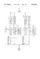
- FIG. 5 is a view of an embodiment of the invention according to the first to fifth aspects, and the seventh and the tenth aspects.
- the input terminal of the receiver 51 1 is connected to the preceding repeater section along the upstream radio transmission line, while the output terminal of the receiver is connected to the input terminal of the demodulator 52 1 .
- the output terminal of the demodulator 52 1 is connected to the input terminal of the intersymbol interference detecting unit (ISI) 53 3 , whose first output terminal is connected to the input terminal of the demultiplexing unit (DMX) 54 1 .
- the first output terminal of the demultiplexing unit 54 1 is connected to the first input terminal of the multiplexing unit (MUX) 55 1 , whose output terminal is connected through the modulator 56 1 to the input terminal of transmitter 57 1 .
- the transmission output terminal of the transmitter 57 1 is connected to the following repeater section along the upstream radio transmission line.
- the input terminal of the receiver 51 2 is connected to the preceding repeater section along the downstream radio transmission line, while the output terminal of the receiver is connected to the input terminal of the demodulator 52 2 .
- the output terminal of the demodulator 52 2 is connected to the input terminal of the intersymbol interference detecting unit (ISI) 53 2 , whose first output terminal is connected to the input terminal of the demultiplexing unit (DMX) 54 2 .
- ISI intersymbol interference detecting unit
- the first output terminal of the demultiplexing unit 54 2 is connected to the first input terminal of the multiplexing unit (MUX) 55 2 , whose output terminal is connected to the modulation input terminal of the transmitter 57 2 through the modulator 56 2 .
- the transmission output terminal of the transmitter 57 2 is connected to the following repeater section along the downstream radio transmission line.
- the second output terminal of the intersymbol interference detecting unit 53 1 is connected to the first input terminals of the adding/selecting units (A/S) 58 11 , 58 21 , while the second output terminal of the intersymbol interference detecting unit 53 2 is connected to the first input terminals of the adding/selecting units (A/S) 58 12 , 58 22 .
- the second output terminal of DMX 54 1 is connected to the second input terminal of the adding/selecting unit 58 11 , whose output terminal is connected to the second input terminal of MUX 55 1 .
- the second output terminal of the demultiplexing unit 54 2 is connected to the second input terminal of the adding/selecting unit 58 22 , whose output terminal is connected to the second input terminal of MUX 55 2 .
- the third output terminal of DMX 54 1 is connected to the second input terminal of the adding/selecting unit 58 12 , whose output terminal is connected to the third input terminal of MUX 55 1 .
- the third output terminal of DMX 54 2 is connected to the second input terminal of the adding/selecting unit 58 22 , while the output terminal is connected to the third input terminal of MUX 55 2 .
- the sections between the output terminals of the intersymbol interference detecting units 53 1 , 53 2 and the input terminals of the modulators 56 1 , 56 2 are connected maintaining correspondence of the channels at the two orthogonally intersecting baseband channels I and Q.
- FIGS. 6A and 6B are views explaining the configuration and operation of an intersymbol interference detecting unit.
- the output terminal of the demodulators 52 1 , 52 2 corresponding to one of the two baseband channels I and Q is connected to the input terminal of the A/D converter 61.
- the output terminal D1 of the two output terminals D1, D2 of the A/D converter 61 is connected to the input terminal of the corresponding demultiplexing unit.
- These two output terminals are connected to the corresponding input terminals of the exclusive OR gate 62.
- the output terminal of the exclusive OR gate 62 is connected to the input terminal of the counter 63.
- a clock whose period and pulse width are set to predetermined value is given to the gate input terminal of the counter.
- the output terminal of the counter 63 is connected to the corresponding input terminals of the multiplexing units 55 1 (or 55 2 ).
- the receiver 51 1 , demodulator 52 1 , DMX 54 1 , receiver 51 2 , demodulator 52 2 , and DMX 54 2 correspond to the regenerating means 11 11 , 11 12 to 11 N1 , 11 N2
- adding/selecting units 58 21 , 58 22 , MUX 55 2 , modulator 56 2 , and transmitter 57 2 correspond to the repeating means 13 11 , 13 12 to 13 N1 , 13 N2
- ISI 53 1 , 53 2 correspond to the intersymbol interference measuring means 15 1 to 15 N .
- FIG. 7 is a view of the operation of the embodiments of the invention.
- the feature of the embodiments, as shown in FIG. 7 and FIG. 16, lies in the provision of the repeater offices 71 1 to 71 3 in place of the repeater offices 122 1 to 122 3 shown in FIG. 16, and each of these repeater offices 71 1 to 71 3 can access the control use transmission line extending from the end office 121 R to the end office 121 S .
- the repeater equipment shown in FIG. 7, further, is provided in each of the repeater offices 71 1 to 71 3 .
- the method of transmission of the control use transmission line and the configuration and operation of the end offices 121 R and 121 S are the same as in the related art, so will not be explained further here.
- the receiver 51 1 and the demodulator 52 1 output the individually corresponding demodulated signals I and Q to the two orthogonally intersecting baseband channels I and Q by receiving and demodulating the received wave from the particular radio transmission line formed with the end office 121 S .
- the A/D converter 61 individually monitors the instantaneous values of the demodulated signals and transforms the relative magnitude of the zero point of the instantaneous value with the reference value ⁇ e symmetric at the positive and negative sides of the zero point into the digital signals shown by the two bits D 1 , D 2 shown in FIG. 6B.
- the exclusive OR gate 62 obtains the exclusive OR of the logical values of the digital signals obtained in this way so as to calculate the eye aperture and generates a binary signal showing if intersymbol interference has occurred.
- the degree of the intersymbol interference in a state where the logical values of the binary signal invert for example, in the case where the absolute value of the reference value ⁇ e is half of the maximum value of the instantaneous value obtainable from an analog signal, as shown in FIG. 19, is transformed into a bit error rate of about "10 -10 ". Accordingly, deterioration of the transmission quality is detected earlier and faster in the invention compared with the related art where the bit errors are found and the relative magnitude with the threshold is judged based on the results of the parity check.
- the counter 63 (FIG. 6A) counts the clock signals during the period that the logical value takes a specific value (here, one showing the state of occurrence of intersymbol interference for simplification) for such a binary signal and judges if the frequency of occurrence of the intersymbol interference exceeds a predetermined value or not as the presence or absence of an overflow. Note that below the binary information showing the result of the above judgement will be referred to as "upstream decision information". Further, the intersymbol interference detecting unit 53 1 gives the above-mentioned demodulated signals I and Q to the demultiplexing unit 54 1 .
- the intersymbol interference detecting unit 53 2 similarly produces "downstream decision information" for the downstream radio transmission line showing if the frequency of occurrence of intersymbol interference exceeds a predetermined value and gives demodulated signals I and Q to the demultiplexing unit 54 2 .
- the demultiplexing unit 54 1 fetches the demodulated signals I and Q given by the intersymbol interference detecting unit 53 1 in the above way, extracts the ISI alarm bits from the X-slot and Y-slot assigned individually to the upstream and downstream radio transmission lines based on the frame configuration shown in FIGS. 8A and 8B, and in parallel demultiplexes the transmission information (data bits) and service bits from the ISI alarm bits.
- the demultiplexing unit 54 2 similarly fetches the demodulated signals I and Q from the downstream radio transmission line given through the receiver 51 2 , demodulator 52 2 , and intersymbol interference detecting unit 53 2 , extracts the ISI alarm bits from the X-slot and Y-slot assigned individually to the downstream and upstream radio transmission lines based on the frame configuration shown in FIGS. 8A and 8B, and in parallel demultiplexes the transmission information (data bits) and service bits from the ISI alarm bits.
- the adding/selecting (A/S) unit 58 21 obtains the logical sum (OR) of the ISI alarm bits extracted from the Y-slot by MUX 54 2 and the upstream decision information obtained by ISI 53 1 in the above way and gives the result to MUX 55 2 . Further, the A/S 58 22 obtains the logical sum (OR) of the ISI alarm bits extracted from the X-slot by DMX 54 2 and the downstream decision information obtained by the intersymbol interference 53 2 in the above way and gives the result to MUX 55 2 .
- A/S 58 12 obtains the logical sum (OR) of the ISI alarm bits extracted from the Y-slot by DMX 54 1 and the downstream decision information obtained by intersymbol interference detecting unit 53 2 in the above way and gives the result to MUX 55 1 .
- A/S 58 11 obtains the logical sum (OR) of the ISI alarm bits extracted from the X-slot by DMX 54 1 and the upstream decision information obtained by ISI 53 1 in the above way and gives the result to MUX 55 1 .
- the multiplexing unit 55 2 places the result of the logical sum obtained by A/S 58 22 at the X-slot and the result of the logical sum obtained by A/S 58 21 at the Y-slot, multiplexes them with the transmission information extracted by DMX 54 2 based on the frame configuration shown in FIGS. 8A and 8B, and sends the result to the following transmission section of the downstream radio transmission line through the modulator 56 2 and transmitter 57 2 .
- MUX 55 1 similarly places the result of the logical sum obtained by the adding/selecting unit 58 11 at the X-slot and the result of the logical sum obtained by A/S 58 12 at the Y-slot, multiplexes them with the transmission information extracted by DMX 54 1 based on the frame configuration shown in FIGS. 8A and 8B, and sends the result to the following transmission section of the upstream radio transmission line through the modulator 56 1 and transmitter 57 1 .
- ISI alarm bits showing this are sent in parallel to the downstream radio transmission line of the preceding repeater section and the following repeater section of the upstream radio transmission line.
- the deterioration of the transmission quality arising due to a notch etc. is detected early and reliably for each repeater section at each repeater office as the degree or frequency of intersymbol interference and thereby the end equipment of the transmitting end and the receiving end can be notified before reaching a state where remarkable bit errors occur.
- the transmission quality can be improved by establishing parallel connecting transmission early by a time substantially equal to the transmission delay between the transmitting end and the receiving end compared with the related art wherein the fact of occurrence of bit errors at the receiving end was notified to the transmitting end only after their occurrence.
- FIG. 9 is a view explaining the operation of an embodiment of the invention according to the first aspect.
- the difference from the configuration shown in FIG. 7 is the provision of the repeater offices 81 1 to 81 3 in place of the repeater offices 71 1 to 71 3 of FIG. 7.
- the configuration of the repeater offices 81 1 to 81 3 is the same as that shown in FIGS. 5 except that A/S 58 12 , 58 21 as shown by the dotted lines in FIG. 5 are not used.
- the ISI alarm bits received from the preceding repeater section along the upstream (downstream) route and the upstream decision information (downstream decision information) obtained by ISI 53 1 (53 2 ) are transmitted to the end office at the receiving end through the repeater transmission route formed by A/S 58 11 , MUX 55 1 , modulator 56 1 , and transmitter 57 1 (A/S 58 22 , MUX 55 2 , modulator 56 2 , and transmitter 57 2 ).
- the end office at the receiving end fetches the thus transmitted ISI alarm bits and sends the request for a parallel connecting transmission to the end office at the transmitting end through an opposite route going back over the same repeater transmission route.
- the ISI alarm bits individually produced by the repeater offices are sent to the receiving end and the request for a parallel connecting transmission is reliably transmitted to the transmitting end, so the configuration of the repeater equipment is simplified, parallel connecting transmission is established earlier than notch growth, and therefore deterioration of the transmission quality can be mitigated better compared with the related art.
- the X-slot and Y-slot are formed as collections of a plurality of bits comprised of the bits individually corresponding to the respective repeater sections.
- A/S's 58 11 , 58 22 fetch the upstream decision information and downstream decision information produced by ISIs 53 1 , 53 2 and give them to the input terminals of MUX's 55 1 , 55 2 corresponding to the X-slot assigned to the following repeater section.
- A/S's 58 12 , 58 21 fetch the downstream decision information and upstream decision information produced by ISIs 53 2 , 53 1 and give them to the input terminals of the MUX's 55 1 , 55 2 corresponding to the Y-slot assigned to the preceding repeater section.
- MUX's 55 1 , 55 2 separate the upstream decision information and downstream decision information given in this way for each repeater section, place them at the respective X-slot and Y-slot, multiplex them together with the transmission information etc., and send them to the adjoining transmission sections.
- the end offices at the transmitting end and the receiving end recognize the upstream decision information and downstream decision information for each transmission section and, when recognizing that intersymbol interference is occurring at one of the transmission sections connected in series with a degree and frequency (or one of the degree and frequency) exceeding a predetermined threshold value, performs a logical decision for the parallel connecting transmission.
- the transmission quality is improved over the related art and it is possible to start communication processing according to the results of recognition of the presence or absence of deterioration of the transmission quality for each transmission section and the degree of the same.
- the X-slot and Y-slot are assigned one each to the upstream radio transmission line and the downstream radio transmission line.
- ISI 53 1 (53 2 ) outputs a value indicative of the degree of intersymbol interference as the upstream decision information (downstream decision information). Note that the processing for obtaining the degree of the intersymbol interference is as explained in the embodiments above, so will not be explained further here.
- A/S 58 11 adds the values shown by the upstream decision information (downstream decision information) produced by ISI 53 1 (53 2 ) and the upstream decision information (downstream decision information) demultiplexed by DMX 54 1 (54 2 ) and gives the sum obtained from the addition to the input terminal of MUX 55 1 (55 2 ) corresponding to the X-slot assigned to the following repeater section.
- the A/S 58 12 fetches the downstream decision information (upstream decision information) produced by ISI 53 2 (53 1 ) and gives it to the input terminal of MUX 55 1 (55 2 ) corresponding to the Y-slot assigned to the following repeater section.
- MUX's 55 1 , 55 2 separate the upstream decision information and downstream decision information given in this way for each repeater section, place them at the respective X-slot and Y-slot, multiplex them together with the transmission information etc., and send them to the adjoining transmission sections.
- the receiving end is notified of the cumulative value of the degrees and frequencies (or one of the degrees and frequencies) of the intersymbol interference occurring at the preceding repeater sections, while the transmitting end is notified of the cumulative value of the frequencies of the intersymbol interference occurring at the repeater sections constituting upstream radio transmission line.
- the end equipment of the transmitting end and the receiving end can recognize the intersymbol interference notified in this way as multilevel information and establish parallel connecting transmission in accordance with the relative magnitude between that value and the predetermined threshold and perform logical decision processing in accordance with that parallel connecting transmission.
- the end equipment at the transmitting end and receiving end can objectively judge at one time the degrees and frequencies (or one of the degrees and frequencies) of the intersymbol interference on the upstream and downstream radio transmission lines and can improve the transmission quality in accordance with the results of the decision and thereby enable optimal control of the communication.
- ISI 53 1 (53 2 ) outputs a value indicative of the degree and frequency of the intersymbol interference (or one of the degree and frequency) as the above-mentioned upstream decision information (downstream decision information).
- A/S 58 11 compares this value and the content of the X-slot received from the preceding repeater section along the upstream (downstream) radio transmission line and demultiplexed by DMX 54 1 (54 2 ) (showing the degree and frequency of the intersymbol interference (or one of the degree and frequency of the intersymbol interference)) and selects the one of the two with the higher degree and frequency (or one of the degree and frequency) of intersymbol interference, and gives to the input terminal corresponding to the X-slot of MUX 55 1 (55 2 ).
- A/S 58 12 similarly compares the value output by ISI 53 2 (53 1 ) and the content of the Y-slot received from the preceding repeater section along the upstream (downstream) radio transmission line and demultiplexed by DMX 54 1 (54 2 ) (showing the frequency of the intersymbol interference in the same way) and selects the one of the two with the higher degree and frequency (or one of the degree and frequency) of intersymbol interference, and gives to the input terminal corresponding to the Y-slot of MUX 55 1 (55 2 ).
- the end equipment of the transmitting end and the receiving end are notified of the maximum values of the degrees and frequencies (or one of the degrees and frequencies) of the intersymbol interference in all of the upstream and downstream repeater sections and can establish parallel connecting transmission and control communications in accordance with the parallel connecting transmission based on the relative magnitude of the maximum values and a predetermined threshold, so the transmission quality can be improved compared with the related art.
- the series of the receiver 51 1 , demodulator 52 1 , ISI 53 1 , DMX 54 1 , MUX 55 1 , demodulator 56 1 , and transmitter 57 1 and the series of the receiver 51 2 , demodulator 52 2 , ISI 53 2 , DMX 54 2 , MUX 55 2 , demodulator 56 2 , and transmitter 57 2 perform regenerative repeating in the same way as the above embodiments, so will not be explained further here.
- ISI 53 1 finds the frequency of the intersymbol interference for the preceding repeater section along the upstream (downstream) radio transmission line and decides the relative magnitude of the frequency with a predetermined upper limit and lower limit. Note that below this series of processing will be referred to as "decision processing”.
- ISI 53 1 (53 2 ) outputs information indicating the fact when the frequency exceeds the above upper limit (hereinafter referred to as “notification of the deterioration of the bit error rate") as the upstream (downstream) decision information and outputs information indicating the fact when the frequency falls below the lower limit (hereinafter referred to as “notification of restoration of the bit error rate”) as upstream (downstream) decision information.
- the series of the receiver 51 1 , demodulator 52 1 , ISI 53 1 , DMX 54 1 , multiplexing unit 55 1 , modulator 56 1 , and transmitter 57 1 and the series of the receiver 51 2 , demodulator 52 2 , ISI 53 2 , DMX 54 2 , MUX 55 2 , modulator 56 2 , and transmitter 57 2 perform regenerative repeating in the same way as the above embodiments, so will not be explained further here.
- the end equipment of the transmitting end and the receiving end are reliably notified of the frequency of the intersymbol interference at the downstream and upstream radio transmission lines and the fact of deterioration or restoration of the bit error rate in accordance with the increment or decrement in that frequency with weighting. In this way, it is possible to start the parallel connecting transmission in accordance with the content notified and control the communication in accordance with the parallel connecting transmission.
- the frequency of the intersymbol interference and the fact that the bit error rate deteriorates or is restored along with the increment and decrement in that frequency are output as upstream (downstream) decision information, but the present invention is not limited to this configuration.
- the intersymbol interference detecting units may output values showing the degree of intersymbol interference as the upstream decision information (downstream decision information) and the above-mentioned decision processing may be performed at the end equipment of the transmitting end and receiving end.
- the feature of this embodiment lies in the procedure of the later explained processing performed in the end equipment of the receiving end.
- the configuration and operation of the repeater office is the same as in the embodiments of the invention according to the first to sixth aspects as shown in FIG. 5, so will not be explained here further.
- the end equipment of the receiving end has a memory (not shown) in which memory areas of predetermined sizes are allotted individually for information obtained through the X-slot regarding the preceding repeater sections of a plurality of upstream radio transmission lines.
- This end equipment fetches the upstream decision information received from the individual radio transmission lines and successively writes it in the memory areas allotted to the corresponding radio transmission lines in the above-mentioned memory areas. Further, the end equipment refers to the upstream decision information written in the memory separately for each radio transmission line in the order of the time sequence so as to determine if the degrees and frequencies of intersymbol interference (or one of the degree and frequency) of the individual radio transmission lines are increasing.
- the end equipment finds the thus determined degree and frequency (or one of the degree and frequency) and the incrementing rate of the same and, for example, when it is necessary to establish parallel connecting transmission for a plurality of radio transmission lines, establishes the parallel connecting transmission preferentially for the radio transmission line with the higher degree and frequency (or one of the degree and frequency) and higher incrementing rate.
- the standby radio transmission line is allotted preferentially to the radio transmission line with the worst deterioration of the transmission quality, the efficiency of utilization of the standby radio transmission line is raised and remarkable deterioration of the transmission quality can be kept to the minimum within the range of the transmission capability of the standby radio transmission line.
- this embodiment compares the degree or frequency of intersymbol interference along with the rate of increase of the intersymbol interference to compare the degree of deterioration of the transmission quality, but the invention is not limited to this configuration.
- the probability of notches occurring simultaneously at a plurality of radio transmission lines is negligibly small, it is also possible for example to compare just the rate of increase of the intersymbol interference.
- FIG. 10 is a view of an embodiment of the invention according to the eighth aspect.
- the input terminal of the hybrid 91 is connected to the output terminal of the end equipment at the transmitting end, not shown.
- the first output terminal of the hybrid 91 is connected to one of the receiving input terminals of the end equipment 92 at the receiving end through the tandem-connected repeater offices 122 11 to 122 31 .
- the second output terminal of the hybrid 91 is connected to the other receiving input terminal of the end equipment 92 through the tandem-connected repeater offices 122 12 to 122 32 .
- the hybrid 91 is mounted in the end equipment of the transmitting end as shown in FIG. 10 and the modulator and other components mounted in the end equipment of the transmitting end are omitted from the illustration for purposes of simplification.
- the operations of the repeater offices 122 11 to 122 31 , 122 12 to 122 32 is the same as in the embodiments of the invention according to the first to sixth aspects explained above, so explanations will be omitted here.
- the end equipment at the transmitting end sends out frames of the configuration shown in FIGS. 8A and 8B. These frames are sent in parallel through the hybrid 91 over the first repeater route comprised of the repeater offices 122 11 to 122 31 and the second repeater route comprised of the repeater offices 122 12 to 122 32 .
- These repeater offices perform regenerative repeating and, like with the embodiments of the invention according to the first to sixth aspects, generate decision information indicative of the intersymbol interference for each repeater section or the frequency of intersymbol interference and send the same to the end equipment 92 through the slot X(Y).
- the end equipment 92 compares the frequency of intersymbol interference for the first repeater route and the second repeater route in the same way as the end equipment of the receiving end in the embodiments of the invention according to the first to sixth aspects and selects and outputs the transmission information received from the repeater route with the smaller frequency.
- the transmission quality of the transmission information selected in this way is kept high and the reliability achieved by duplexing of the repeater routes is further enhanced.
- FIG. 11 is a view of an embodiment of the invention according to the ninth aspect.
- the antenna 101 1 is connected to the input terminal of the receiver 102 1 , whose output terminal is connected through the demodulator 103 1 to one of the input terminals of the logical decision control unit 104 and one of the input terminals of the switch 105.
- the antenna 101 2 is connected to the input terminal of the receiver 102 2 , whose output terminal is connected through the demodulator 103 2 to the other of the input terminals of the logical decision control unit 104 and the other of the input terminals of the switch 105.
- the output terminal of the logical decision control unit 104 is connected to the control input terminal of the switch 105, from whose output terminal a demodulated signal is obtained.
- the receiver 102 1 and the demodulator 103 1 receive the wave arriving at the installation point of the antenna 101 1 forming the first branch and demodulate the same to output a first demodulated signal.
- the receiver 102 2 and demodulator 103 2 receive the wave arriving at the installation point (point a predetermined distance away from the installation point of the antenna 101 1 ) of the antenna 101 2 forming the second branch and demodulate the same to output a second demodulated signal.
- the logic decision control unit 104 fetches the first demodulated signal and the second demodulated signal and in the same way as the intersymbol interference detecting units 53 1 (53 2 ) of the embodiments of the invention according to the first to sixth aspects finds the respective frequencies of intersymbol interference and judges the relative magnitude between the two.
- the switch 105 selects and outputs the signal with the smaller frequency of intersymbol interference among the first demodulated signal and the second demodulated signal in accordance with the relative magnitude decided in this way.
- the branch with the best transmission quality can be reliably selected from the results of the comparison of the frequencies of intersymbol interference at the branches even in a state where the transmission qualities are all excellent as compared with the conventional space diversity method where switching was based on merely the results of comparison of the intensity of the received field.
- FIGS. 12A and 12B are views of an embodiment of the invention according to the tenth aspect.
- a 4-bit A/D converter 111 is arranged at the first stage.
- the inverted logical value of the bit D3 of the LSB and the adjoining upper bit D2 in the output of the A/D converter are applied to the corresponding input terminals of the exclusive OR gate 112 1 .
- the bit D2 and the adjoining upper bit D1 are applied to the corresponding input terminals of the exclusive OR gate 112 2 .
- the output of the gate is applied to the input terminal of the counter 113 1 and one of the input terminals of AND gate 114.
- the output of the exclusive OR gate 112 1 is applied to the other of the input terminals of the AND gate 114, while the output of the AND gate 114 is applied to the input terminal of the counter 113 2 .
- the output of the counter 113 1 is applied to the first output terminal 116 1 through the latch 115 1 , while the output of the counter 113 2 is applied to the second output terminal 116 2 through the latch 115 2 .
- the A/D converter 111 fetches the baseband signal I (or Q) given from the demodulator 52 1 (52 1 ) and successively transforms the instantaneous value of the amplitude to binary code digital signals D1 to D4 of a 4-bit length.
- the exclusive OR gate 112 2 obtains the exclusive OR of the logical value of the bit D1 and the logical value of the bit D2 in the bits comprising the digital signals so as to decide if the eye aperture exceeds a predetermined threshold and outputs the result of decision as the first binary information.
- the exclusive OR gate 112 1 obtains the exclusive OR of the logical value of the bit D2 and the inverted logical value of the bit D3 and obtains the logical product with the first binary information and outputs the second binary information.
- the counters 113 1 and 113 2 in the same way as the counter 63 shown in FIG. 6A, produce and output the decision information (hereinafter referred to as the "first decision information” and “second decision information”) from the first binary information and the second binary information.
- the latches 115 1 and 115 2 fetch the first and second decision information output from the counters 113 1 and 113 2 in this way (corresponding to upstream radio transmission line and downstream radio transmission line, respectively) and hold the already obtained decision information even while these counters perform a following counting operation.
- the thresholds of the intersymbol interference are determined by the combination of the bits given to the exclusive OR gates 112 1 and 112 2 , so as shown in FIG. 12B, the threshold corresponding to the first binary information becomes a value larger than the threshold corresponding to the second binary information. Accordingly, the first decision information is obtained as a result of detection of the intersymbol interference with a higher sensitivity than the second decision information.
- A/S's 58 12 and 58 21 place the second decision information in the Y-slot of the downstream radio transmission line, while A/S's 58 11 and 58 22 place the first decision information in the X-slot of the upstream radio transmission line. Further, in the process of occurrence or growth of the notches, the second decision information is obtained before the first decision information.
- the second decision information is sent to the transmitting end before the first decision information is sent to the receiving end, so parallel connecting transmission is established at the transmitting end before the time the receiving end performs synchronous control in accordance with parallel connecting transmission and changes transmission information under synchronous control. Accordingly, the efficiency of the parallel-connecting transmission is improved and the efficiency of use of the standby radio transmission line is enhanced.
- the combinations of the bits input to the exclusive OR gates 112 1 and 112 2 and the thresholds relating to the generation of first decision information and second decision information based on the logical operations performed by the exclusive OR gates and AND gate 114 are set, but the present invention is not limited to these.
- the A/D converter 111 is a parallel type A/D converter
- FIGS. 13A and 13B are views of a first modification of the embodiment shown in FIGS. 12A and 12B.
- the bit D3 of FIG. 12A is input to the exclusive OR gate 112, without being logically inverted as in FIG. 13A. Further, there is the difference that the AND gate 114 of FIG. 12A is replaced by the OR gate 117 in FIG. 13A.
- FIGS. 14A and 14B are views of a second modification of the embodiment shown in FIGS. 12A and 12B.
- FIG. 14A Comparing FIG. 14A and FIG. 12A, in FIG. 14A, the exclusive OR gate 112 3 is added and the AND gate 118 and the OR gate 117 are added as compared with FIG. 12A.
- the sensitivity of detection of intersymbol interference shown in FIG. 14B is the lowest in level compared with FIG. 12B and FIG. 13B.
- the configuration of FIG. 14A is adopted when there are not any stringent demands on the transmission quality of the radio transmission line.
- 4-value QAM was adopted for the upstream and downstream radio transmission lines, but the present invention is not limited to this method of modulation.
- an N+1 standby system was adopted as the redundant configuration of the radio transmission lines, but the present invention is not limited to this standby system.
- it may also be applied to an N+2 standby system or a duplexed system.
- the decision information are multiplexed with the transmission information etc. by the time division multiplex mode and sent to the transmitting end or the receiving end, but the present invention is not limited to this multiplexing mode. It may be applied to a frequency multiplexing mode, CDMA mode, or any other multiplexed transmission mode so long as the decision information can be multiplexed for transmission without causing unallowable errors.
- FIGS. 15A to 15F are views explaining specific examples of the adding/selecting unit shown in FIG. 5.
- FIG. 15A shows an example of the adding unit 58A which adds two inputs comprised of binary signals to obtain a binary output.
- the adding unit 58A comprises an OR circuit.
- FIG. 15B shows a selecting unit 58S for selecting the larger of two inputs comprised of binary signals to obtain a binary output.
- This also comprises an OR circuit. For example, if the input 1 is “1" and the input 2 is “0”, the larger binary signal becomes the output ("1").
- FIG. 15C is an adding unit 58A which adds inputs comprised of quaternary signals (MSB1, MSB2, LSB1, and LSB2) to obtain a quaternary signal output. As illustrated, it comprises four OR circuits and four AND circuits.
- FIG. 15E is a truth table showing the operation of the adding unit 58A of FIG. 15C.
- FIG. 15D is a selecting unit 58S for selecting the larger of the input 1 and input 2. Both are quaternary signals inputs (MSB1, MSB2, LSB1, and LSB2) to obtain a quaternary output. As illustrated, it is comprised of three OR circuits and four AND circuits.
- FIG. 15F is a truth table showing the operation of the selecting unit 58S of FIG. 15D.
- a light deterioration of the transmission characteristics is measured as the degree or frequency of intersymbol interference and the degrees or frequencies of intersymbol interference along the upstream (downstream) routes of the individual radio transmission lines are directly sent to the upstream and/or downstream routes.
- the state of fluctuation of the transmission characteristics at the preceding repeater section is quickly and reliably notified to the transmitting end or the receiving end.
- the transmitting end or receiving end it therefore becomes possible to smoothly reconstruct the redundantly configured radio transmission lines and control communication based on the predetermined protocol in accordance with the state of fluctuation of the transmission characteristics notified in this way.
- the fourth aspect at a repeating point of the full duplex redundantly configured radio transmission lines, information indicative of the sum of the degrees or frequencies of intersymbol interference measured in each preceding repeater section along the upstream (downstream) routes of the radio transmission lines is quickly and reliably notified to the receiving end and/or the transmitting end through the upstream and/or downstream routes.
- the largest value of the degree or frequency of intersymbol interference measured in each preceding repeater section in the upstream (downstream) routes of the radio transmission lines is quickly and reliably notified to the receiving end and/or the transmitting end through the upstream and/or downstream routes of the following repeater sections.
- the transmitting end and/or receiving end it is possible to smoothly reconstruct the redundantly configured radio transmission lines and control the communication based on a predetermined protocol in accordance with the state of fluctuation of the transmission characteristics notified in this way.
- the transmitting end and/or receiving end it is possible to smoothly reconstruct the redundantly configured radio transmission lines and control the communication based on a predetermined protocol in accordance with the state of fluctuation of the transmission characteristics of the radio transmission lines.
- the transmission information and control information are sent through the transmission line with the smaller degree of intersymbol interference or deterioration of quality in the duplexed radio transmission lines. Accordingly, it is possible to maintain the transmission quality high and keep the reliability of the transmission line good not only when the transmission characteristics differ significantly among the radio transmission lines, but also when the transmission characteristics are all good.
- the transmission characteristics can be maintained good with a high reliability compared with the conventional space diversity method where branches were switched at the timing when the transmission quality fell below a predetermined value.
- the increase of the degree or frequency of intersymbol interference is notified to the transmitting end prior to the receiving end back over the preceding repeater sections in the process of deterioration of the transmission characteristics in the preceding repeater sections, so the redundantly configured radio transmission lines can be reconstructed and communication controlled efficiently.
Landscapes
- Engineering & Computer Science (AREA)
- Computer Networks & Wireless Communication (AREA)
- Signal Processing (AREA)
- Radio Relay Systems (AREA)
- Time-Division Multiplex Systems (AREA)
- Mobile Radio Communication Systems (AREA)
Applications Claiming Priority (2)
| Application Number | Priority Date | Filing Date | Title |
|---|---|---|---|
| JP7-081040 | 1995-04-06 | ||
| JP7081040A JPH08279781A (ja) | 1995-04-06 | 1995-04-06 | 中継装置、端局装置および受信機 |
Publications (1)
| Publication Number | Publication Date |
|---|---|
| US5875209A true US5875209A (en) | 1999-02-23 |
Family
ID=13735339
Family Applications (1)
| Application Number | Title | Priority Date | Filing Date |
|---|---|---|---|
| US08/629,389 Expired - Fee Related US5875209A (en) | 1995-04-06 | 1996-04-08 | Digital radio system including repeater equipment, end equipment and receiver |
Country Status (3)
| Country | Link |
|---|---|
| US (1) | US5875209A (ja) |
| EP (1) | EP0736982A3 (ja) |
| JP (1) | JPH08279781A (ja) |
Cited By (9)
| Publication number | Priority date | Publication date | Assignee | Title |
|---|---|---|---|---|
| US20020093926A1 (en) * | 2000-12-05 | 2002-07-18 | Kilfoyle Daniel B. | Method and system for a remote downlink transmitter for increasing the capacity of a multiple access interference limited spread-spectrum wireless network |
| US20030215237A1 (en) * | 2002-02-01 | 2003-11-20 | Hiroto Sugahara | Wavelength-division multiplexing optical transmission system and optical communication method |
| US6690657B1 (en) | 2000-02-25 | 2004-02-10 | Berkeley Concept Research Corporation | Multichannel distributed wireless repeater network |
| US7006461B2 (en) | 2001-09-17 | 2006-02-28 | Science Applications International Corporation | Method and system for a channel selective repeater with capacity enhancement in a spread-spectrum wireless network |
| US7061891B1 (en) | 2001-02-02 | 2006-06-13 | Science Applications International Corporation | Method and system for a remote downlink transmitter for increasing the capacity and downlink capability of a multiple access interference limited spread-spectrum wireless network |
| WO2007148871A1 (en) * | 2006-06-19 | 2007-12-27 | Spacelink Corp. | Asymmetric relay communication system between up-and down-links |
| US20090180404A1 (en) * | 2008-01-14 | 2009-07-16 | Samsung Electronics Co., Ltd. | Apparatus and method for interference cancellation and synchronization maintenance over interference channel estimation in communication system based on full-duplex relay |
| US7630344B1 (en) | 2001-03-30 | 2009-12-08 | Science Applications International Corporation | Multistage reception of code division multiple access transmissions |
| CN110999128A (zh) * | 2017-08-02 | 2020-04-10 | 高通股份有限公司 | 使用网状网络来共享关键飞行信息 |
Families Citing this family (4)
| Publication number | Priority date | Publication date | Assignee | Title |
|---|---|---|---|---|
| US5787344A (en) | 1994-06-28 | 1998-07-28 | Scheinert; Stefan | Arrangements of base transceiver stations of an area-covering network |
| US6125109A (en) * | 1998-02-24 | 2000-09-26 | Repeater Technologies | Delay combiner system for CDMA repeaters and low noise amplifiers |
| DE10022182B4 (de) * | 2000-05-06 | 2010-02-11 | Oebel, Beate | Verfahren zur Versendung elektronischer Textnachrichten über eine Datenverbindung |
| JP4363828B2 (ja) * | 2002-08-30 | 2009-11-11 | 株式会社東芝 | 中継放送波切替装置 |
Citations (4)
| Publication number | Priority date | Publication date | Assignee | Title |
|---|---|---|---|---|
| JPS615658A (ja) * | 1984-06-01 | 1986-01-11 | Fujitsu Ltd | 信号監視回路 |
| US4766606A (en) * | 1987-05-21 | 1988-08-23 | Dell Canada Marketing Corp. | Signal repeater for multi subscriber communication over single pair telephone line |
| US5291519A (en) * | 1991-02-22 | 1994-03-01 | Nec Corporation | Digital mobile communications terminal equipment and receiving method therefor |
| US5303261A (en) * | 1991-11-29 | 1994-04-12 | General Electric Company | High-throughput pipelined communication channel for interruptible data transmission |
Family Cites Families (4)
| Publication number | Priority date | Publication date | Assignee | Title |
|---|---|---|---|---|
| DE3227259C2 (de) * | 1982-07-21 | 1986-04-24 | Siemens AG, 1000 Berlin und 8000 München | Richtfunkstation |
| CA2107857C (en) * | 1992-10-09 | 1998-05-05 | Osamu Kagami | Hybrid digital radio-relay system |
| JP2649766B2 (ja) * | 1993-01-20 | 1997-09-03 | 国際電信電話株式会社 | 等化後選択合成ダイバーシチ受信方式 |
| US5351274A (en) * | 1993-08-20 | 1994-09-27 | General Electric Company | Post detection selection combining diversity receivers for mobile and indoor radio channels |
-
1995
- 1995-04-06 JP JP7081040A patent/JPH08279781A/ja not_active Withdrawn
-
1996
- 1996-04-04 EP EP96105447A patent/EP0736982A3/en not_active Withdrawn
- 1996-04-08 US US08/629,389 patent/US5875209A/en not_active Expired - Fee Related
Patent Citations (4)
| Publication number | Priority date | Publication date | Assignee | Title |
|---|---|---|---|---|
| JPS615658A (ja) * | 1984-06-01 | 1986-01-11 | Fujitsu Ltd | 信号監視回路 |
| US4766606A (en) * | 1987-05-21 | 1988-08-23 | Dell Canada Marketing Corp. | Signal repeater for multi subscriber communication over single pair telephone line |
| US5291519A (en) * | 1991-02-22 | 1994-03-01 | Nec Corporation | Digital mobile communications terminal equipment and receiving method therefor |
| US5303261A (en) * | 1991-11-29 | 1994-04-12 | General Electric Company | High-throughput pipelined communication channel for interruptible data transmission |
Non-Patent Citations (4)
| Title |
|---|
| International Telecommunication Union (ITU) Telecommunication Standardization Sector Study Group 13 -- Contribution 4, COM 13-4-E, "Recommendation G.826: Error Performance Parameters and Objectives for International, Constant Bit Rate Digital Paths At or Above the Primary Rate," Mar. 1993, pp. 1-19. |
| International Telecommunication Union (ITU) Telecommunication Standardization Sector Study Group 13 Contribution 4, COM 13 4 E , Recommendation G.826: Error Performance Parameters and Objectives for International, Constant Bit Rate Digital Paths At or Above the Primary Rate, Mar. 1993, pp. 1 19. * |
| Meyer, J., "Implications of Draft New ITU-T Recommendation G.826 on Digital Radio-Relay Systems," Radio Relay Systems, Oct. 11-14, 1993, Conference Publication No. 386, pp. 21-28. |
| Meyer, J., Implications of Draft New ITU T Recommendation G.826 on Digital Radio Relay Systems, Radio Relay Systems , Oct. 11 14, 1993, Conference Publication No. 386, pp. 21 28. * |
Cited By (20)
| Publication number | Priority date | Publication date | Assignee | Title |
|---|---|---|---|---|
| US6690657B1 (en) | 2000-02-25 | 2004-02-10 | Berkeley Concept Research Corporation | Multichannel distributed wireless repeater network |
| US20020093926A1 (en) * | 2000-12-05 | 2002-07-18 | Kilfoyle Daniel B. | Method and system for a remote downlink transmitter for increasing the capacity of a multiple access interference limited spread-spectrum wireless network |
| US7016332B2 (en) | 2000-12-05 | 2006-03-21 | Science Applications International Corporation | Method and system for a remote downlink transmitter for increasing the capacity of a multiple access interference limited spread-spectrum wireless network |
| US7061891B1 (en) | 2001-02-02 | 2006-06-13 | Science Applications International Corporation | Method and system for a remote downlink transmitter for increasing the capacity and downlink capability of a multiple access interference limited spread-spectrum wireless network |
| US7535867B1 (en) | 2001-02-02 | 2009-05-19 | Science Applications International Corporation | Method and system for a remote downlink transmitter for increasing the capacity and downlink capability of a multiple access interference limited spread-spectrum wireless network |
| US7630344B1 (en) | 2001-03-30 | 2009-12-08 | Science Applications International Corporation | Multistage reception of code division multiple access transmissions |
| US7936711B2 (en) | 2001-09-17 | 2011-05-03 | Science Applications International Corporation | Method and system for a channel selective repeater with capacity enhancement in a spread-spectrum wireless network |
| US7710913B2 (en) | 2001-09-17 | 2010-05-04 | Science Applications International Corporation | Method and system for a channel selective repeater with capacity enhancement in a spread-spectrum wireless network |
| US20060077927A1 (en) * | 2001-09-17 | 2006-04-13 | Kilfoyle Daniel B | Method and system for a channel selective repeater with capacity enhancement in a spread-spectrum wireless network |
| US20060083196A1 (en) * | 2001-09-17 | 2006-04-20 | Kilfoyle Daniel B | Method and system for a channel selective repeater with capacity enhancement in a spread-spectrum wireless network |
| US20060077920A1 (en) * | 2001-09-17 | 2006-04-13 | Kilfoyle Daniel B | Method and system for a channel selective repeater with capacity enhancement in a spread-spectrum wireless network |
| US7006461B2 (en) | 2001-09-17 | 2006-02-28 | Science Applications International Corporation | Method and system for a channel selective repeater with capacity enhancement in a spread-spectrum wireless network |
| US7194208B2 (en) * | 2002-02-01 | 2007-03-20 | Nec Corporation | Wavelength-division multiplexing optical transmission system and optical communication method |
| US20030215237A1 (en) * | 2002-02-01 | 2003-11-20 | Hiroto Sugahara | Wavelength-division multiplexing optical transmission system and optical communication method |
| WO2007148871A1 (en) * | 2006-06-19 | 2007-12-27 | Spacelink Corp. | Asymmetric relay communication system between up-and down-links |
| US20090180404A1 (en) * | 2008-01-14 | 2009-07-16 | Samsung Electronics Co., Ltd. | Apparatus and method for interference cancellation and synchronization maintenance over interference channel estimation in communication system based on full-duplex relay |
| US8155046B2 (en) * | 2008-01-14 | 2012-04-10 | Samsung Electronics Co., Ltd. | Apparatus and method for interference cancellation and synchronization maintenance over interference channel estimation in communication system based on full-duplex relay |
| CN110999128A (zh) * | 2017-08-02 | 2020-04-10 | 高通股份有限公司 | 使用网状网络来共享关键飞行信息 |
| US10713956B2 (en) * | 2017-08-02 | 2020-07-14 | Qualcomm Incorporated | Sharing critical flight information using mesh network |
| US10803754B2 (en) | 2017-08-02 | 2020-10-13 | Qualcomm Incorporated | Directional beam mesh network for aircraft |
Also Published As
| Publication number | Publication date |
|---|---|
| EP0736982A3 (en) | 2000-07-12 |
| JPH08279781A (ja) | 1996-10-22 |
| EP0736982A2 (en) | 1996-10-09 |
Similar Documents
| Publication | Publication Date | Title |
|---|---|---|
| US5875209A (en) | Digital radio system including repeater equipment, end equipment and receiver | |
| US5245633A (en) | System for transmitting digital data over an electricity power line | |
| US8660425B2 (en) | Optical transmitting device and optical receiving device | |
| US4891806A (en) | Constellation multiplexed inband secondary channel for voiceband modem | |
| KR100884840B1 (ko) | 빠른 동적 링크 적응을 실행하는 사용자 장치 | |
| US5577196A (en) | Intelligent digital signal hitless protection switch | |
| US7990931B2 (en) | Methods and devices for selecting sets of available sub-channels | |
| US20020163936A1 (en) | Bit-level control for dynamic bandwidth allocation | |
| JP3589992B2 (ja) | 通信装置及び伝送方式選択方法 | |
| DK165091B (da) | Fremgangsmaade og kobling til synkronisering af modtagerudstyret i et digitalt multiplekstransmissionsanlaeg | |
| JP4469724B2 (ja) | 2×2無線ローカルエリアネットワーク、cofdm−mimoシステムにおける復号器及び復号方法 | |
| US4967406A (en) | Subsignal transmitting system | |
| US5408475A (en) | Modem with transient impairment detector | |
| US11588550B2 (en) | Optical transmission device and optical transmission system | |
| KR101430853B1 (ko) | 통신 노드 장치, 통신 시스템 및 그들에 이용되는 목적지 수신 인터페이스 선택 방법 | |
| Ohta et al. | Hitless line protection method for ATM networks | |
| KR101181754B1 (ko) | Diversity 결합 기법과 적응형 전송기법을 이용한 SFH 시스템의 항재밍 성능 개선 방법 및 장치 | |
| AU743536B2 (en) | Method for transmitting additional data signals and a useful data signal by means of optical links | |
| Das | Review of digital communication | |
| RU2562812C2 (ru) | Устройство беспроводной передачи, система беспроводной передачи и способ управления устройством беспроводной передачи | |
| JPS59178842A (ja) | デ−タ通信システム | |
| RU2774379C1 (ru) | Способ повышения пропускной способности и качества оценки коротковолновых каналов связи с абсолютно-биимпульсными сигналами при их адаптации к условиям связи | |
| EP0872083B1 (en) | Implementing a fault-tolerant bus in a telecommunications network | |
| KR20050004603A (ko) | 다중 채널 통신 시스템의 수신기 및 상기 수신기를 사용한데이터 복원방법 | |
| JPH098706A (ja) | ホットスタンバイ回線切替方式 |
Legal Events
| Date | Code | Title | Description |
|---|---|---|---|
| AS | Assignment |
Owner name: FUJITSU LIMITED, JAPAN Free format text: ASSIGNMENT OF ASSIGNORS INTEREST;ASSIGNOR:OGATA, ISAO;REEL/FRAME:007957/0088 Effective date: 19960327 |
|
| CC | Certificate of correction | ||
| FPAY | Fee payment |
Year of fee payment: 4 |
|
| FEPP | Fee payment procedure |
Free format text: PAYER NUMBER DE-ASSIGNED (ORIGINAL EVENT CODE: RMPN); ENTITY STATUS OF PATENT OWNER: LARGE ENTITY Free format text: PAYOR NUMBER ASSIGNED (ORIGINAL EVENT CODE: ASPN); ENTITY STATUS OF PATENT OWNER: LARGE ENTITY |
|
| REMI | Maintenance fee reminder mailed | ||
| LAPS | Lapse for failure to pay maintenance fees | ||
| STCH | Information on status: patent discontinuation |
Free format text: PATENT EXPIRED DUE TO NONPAYMENT OF MAINTENANCE FEES UNDER 37 CFR 1.362 |
|
| FP | Lapsed due to failure to pay maintenance fee |
Effective date: 20070223 |