US6540561B1 - Locking mechanism for securely preventing disconnection between a plug and a receptacle - Google Patents
Locking mechanism for securely preventing disconnection between a plug and a receptacle Download PDFInfo
- Publication number
- US6540561B1 US6540561B1 US09/634,976 US63497600A US6540561B1 US 6540561 B1 US6540561 B1 US 6540561B1 US 63497600 A US63497600 A US 63497600A US 6540561 B1 US6540561 B1 US 6540561B1
- Authority
- US
- United States
- Prior art keywords
- plug
- connector
- receptacle
- contact
- principal surface
- Prior art date
- Legal status (The legal status is an assumption and is not a legal conclusion. Google has not performed a legal analysis and makes no representation as to the accuracy of the status listed.)
- Expired - Lifetime
Links
Images


Classifications
-
- H—ELECTRICITY
- H01—ELECTRIC ELEMENTS
- H01R—ELECTRICALLY-CONDUCTIVE CONNECTIONS; STRUCTURAL ASSOCIATIONS OF A PLURALITY OF MUTUALLY-INSULATED ELECTRICAL CONNECTING ELEMENTS; COUPLING DEVICES; CURRENT COLLECTORS
- H01R13/00—Details of coupling devices of the kinds covered by groups H01R12/70 or H01R24/00 - H01R33/00
- H01R13/64—Means for preventing incorrect coupling
-
- H—ELECTRICITY
- H01—ELECTRIC ELEMENTS
- H01R—ELECTRICALLY-CONDUCTIVE CONNECTIONS; STRUCTURAL ASSOCIATIONS OF A PLURALITY OF MUTUALLY-INSULATED ELECTRICAL CONNECTING ELEMENTS; COUPLING DEVICES; CURRENT COLLECTORS
- H01R13/00—Details of coupling devices of the kinds covered by groups H01R12/70 or H01R24/00 - H01R33/00
- H01R13/40—Securing contact members in or to a base or case; Insulating of contact members
- H01R13/405—Securing in non-demountable manner, e.g. moulding, riveting
-
- H—ELECTRICITY
- H01—ELECTRIC ELEMENTS
- H01R—ELECTRICALLY-CONDUCTIVE CONNECTIONS; STRUCTURAL ASSOCIATIONS OF A PLURALITY OF MUTUALLY-INSULATED ELECTRICAL CONNECTING ELEMENTS; COUPLING DEVICES; CURRENT COLLECTORS
- H01R13/00—Details of coupling devices of the kinds covered by groups H01R12/70 or H01R24/00 - H01R33/00
- H01R13/02—Contact members
- H01R13/20—Pins, blades, or sockets shaped, or provided with separate member, to retain co-operating parts together
-
- H—ELECTRICITY
- H01—ELECTRIC ELEMENTS
- H01R—ELECTRICALLY-CONDUCTIVE CONNECTIONS; STRUCTURAL ASSOCIATIONS OF A PLURALITY OF MUTUALLY-INSULATED ELECTRICAL CONNECTING ELEMENTS; COUPLING DEVICES; CURRENT COLLECTORS
- H01R12/00—Structural associations of a plurality of mutually-insulated electrical connecting elements, specially adapted for printed circuits, e.g. printed circuit boards [PCB], flat or ribbon cables, or like generally planar structures, e.g. terminal strips, terminal blocks; Coupling devices specially adapted for printed circuits, flat or ribbon cables, or like generally planar structures; Terminals specially adapted for contact with, or insertion into, printed circuits, flat or ribbon cables, or like generally planar structures
- H01R12/70—Coupling devices
- H01R12/71—Coupling devices for rigid printing circuits or like structures
- H01R12/712—Coupling devices for rigid printing circuits or like structures co-operating with the surface of the printed circuit or with a coupling device exclusively provided on the surface of the printed circuit
- H01R12/716—Coupling device provided on the PCB
Definitions
- An electrical connector is used for electrically connecting printed circuit boards or electrically connecting a printed circuit board and an electrical cable such as a flexible printed circuit (hereinafter referred to as “FPC”).
- Such an electrical connector normally includes a plug connector and a receptacle connector to be connected to the plug connector.
- Japanese Patent No. 2676063 is a locking mechanism for engaging contacts of the plug connector with contacts of the receptacle connector. Since the contacts are normally made of material such as metal that is hard to be worn against the rubbing, the deterioration of the locking mechanism as a result of repeated insertion of the plug connector into the receptacle connector is extremely low.
- the locking mechanism has the following problems.
- an outer surface of a mold may rub the contact surfaces of the contacts when the mold is released.
- the contact surfaces of the contacts may be scratched so that surface treatment including gold plating on the contact surfaces and/or sealing provided for treating the gold plating is affected. In this case, it is difficult to provide suitable electrical contact.
- an electrical connector comprising a plug connector and a receptacle connector which are adapted to be connected to each other in a first direction
- the plug connector comprising a plug housing and a plug contact held by the plug housing
- the receptacle connector comprising a receptacle housing and a receptacle contact held by the a receptacle housing for coming in contact with the plug contact when the plug connector is connected to the receptacle connector
- one of the plug contact and the receptacle contact having a principal surface extending along the first direction, a concave portion recessed from the principal surface in a second direction perpendicular to the first direction, and a wall between the principal surface and the concave portion, another of the plug contact and the receptacle contact having a projection which is positioned inside the concave portion when the plug connector is connected to the receptacle connector.
- a plug connector for being connected to a receptacle connector in a first direction
- the plug connector comprising a plug housing and a plurality of plug contacts held by the plug housing for coming in contact with the receptacle connector, each of the plug contacts having a principal surface extending along the first direction, a concave portion recessed from the principal surface in a second direction perpendicular to the first direction, and a wall between the principal surface and the concave portion.
- a receptacle connector for being connected to the above-mentioned plug connector, the receptacle connector comprising a receptacle housing and a plurality of receptacle contacts held by the receptacle housing for coming in contact with the first-mentioned contact portion in the second direction, each of the receptacle contacts having a projection which is positioned inside the concave portion when the plug connector is connected to the receptacle connector.
- FIG. 1 is a perspective view showing a plug connector included in an electrical connector according to a first embodiment of the present invention
- FIG. 4A is a sectional view taken along a line IVa—IVa of FIG. 3;
- FIG. 4B is a sectional view taken along a line IVb—IVb of FIG. 3;
- FIG. 4C is a sectional view taken along a line IVc—IVc of FIG. 3;
- FIG. 5 is a perspective view showing a receptacle connector included in the electrical connector according to the first embodiment of the present invention
- FIG. 6 is a front view of the receptacle connector shown in FIG. 5;
- FIG. 7A is a sectional view taken along a line VIIa—VIIa of FIG. 6;
- FIG. 7C is a sectional view taken along a line VIIc—VIIc of FIG. 6;
- FIG. 8 is an explanatory view showing the plug connector of FIG. 1 and the receptacle connector of FIG. 5 before the connection;
- FIG. 9 is an explanatory view showing the plug connector of FIG. 1 and the receptacle connector of FIG. 5 connected to each other;
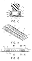
- FIG. 11 is a perspective view showing a plug connector included in an electrical connector according to a second embodiment of the present invention.
- FIG. 12 is a front view of the plug connector of FIG. 11;
- FIG. 13A is a sectional view taken along a line XIIIa—XIIIa of FIG. 12;
- FIG. 13B is a sectional view taken along a line XIIIb—XIIIb of FIG. 12;
- FIG. 13C is a sectional view taken along a line XIIIc—XIIIc of FIG. 12 .
- the electrical connector includes a plug connector 1 and a receptacle connector 2 which are connected to or disconnected from each other in a first direction.
- the following description will be made assuming that the plug connector 1 and the receptacle connector 2 are arranged on a circuit board, but it should be understood that the present invention is not limited thereto.
- the plug connector 1 includes a plug housing 11 made of an insulating material such as synthetic resin and a plurality of plug contacts 13 and 14 parts of which are fixed and held in a plurality of parallel grooves 12 formed in the housing 11 .
- the contacts 13 are aligned in parallel on the left side of the housing 11 in FIGS. 4A-4C.
- the contacts 14 are aligned in parallel on the right side of the housing 11 in FIG. 1 .
- Each of the contacts 13 has a board connecting portion 13 a connected by soldering or the like to an electrical circuit on the circuit board (not shown) on which the plug connector 1 is arranged and a contact portion 13 b which comes in contact with a corresponding contact of the receptacle connector 2 when the plug connector 1 is connected to the receptacle connector 2 .
- Each of the contacts 14 has a board connecting portion 14 a and a contact portion 14 b which are similar to the board connecting portion 13 a and the contact portion 13 b , respectively.
- the contacts 13 have the same configuration and the same size as those of the contacts 14 , the configuration of the contacts 13 may be different from that of the contacts 14 , for example, in that concave portions are formed in different positions.
- the contact portion 13 b has a principal flat surface 13 d formed with a concave portion 13 c having a surrounding wall 13 e . More particularly, the contact portion 13 b has the principal flat surface 13 d , the concave portion 13 c recessed from the principal flat surface 13 d in a second direction perpendicular to the first direction, and the wall 13 e surrounding the concave portion 13 c between the principal flat surface 13 d and the concave portion 13 c .
- the concave portion 13 c can be formed for example by coining a relating portion of the plug contact 13 .
- the concave portion 13 c are quadrate in the illustrative example, it is not limited thereto and may be circular or elliptical in form. It is to be noted that the other plug contact 14 b has structure similar to that of the above-mentioned plug contact 13 .
- the receptacle connector 2 includes a receptacle housing 21 made of an insulating material such as synthetic resin and a plurality of receptacle contacts 23 parts of which are fixed and held in a plurality of parallel grooves 22 formed in the housing 21 .
- the receptacle connector 2 is provided with spaces 24 and 25 for fitting the plug connector 1 therein.
- Each of the receptacle contacts 23 has a board connecting portion 23 a connected by soldering or the like to an electrical circuit on a circuit board (not shown) on which the receptacle connector 2 is arranged, a contact portion 23 b which comes in elastic contact with a corresponding contact of the plug connector 1 when the plug connector 1 is connected to the receptacle connector 2 , and a press fitting portion 23 c inserted into the housing 21 .
- the contact portion 23 b is formed at one end thereof with a projection 23 d protruding in the second direction.
- the contact portion 23 b has substantially a C-like configuration extending from the board connecting portion 23 a and the press fitting portion 23 c . Because of this configuration, the contact portion 23 b has elasticity (like a spring) in the second direction or the right-left direction of FIG. 7 A.
- the plug connector 1 and the receptacle connector 2 are connected to each other.
- the plug connector 1 is positioned above the receptacle connector 2 to face the plug connector 1 with the spaces 24 and 25 of the receptacle connector 2 as shown in FIG. 8 .
- the plug connector 1 is fitted into the spaces 24 and 25 .
- the plug connector 1 and the receptacle connector 2 are connected to each other so that the contact portions 13 b and 14 b of the contacts 13 and 14 of the plug connector 1 come in contact with the contact portions 23 b of the contacts 23 of the receptacle connector 2 as shown in FIG. 9 .
- the contact portions 23 b of the contacts 23 are elastic as mentioned above, the contact portions 13 b and 14 b are in elastic contact with the contact portions 23 .
- the projection 23 d of the contact portion 23 b of the each contact 23 is inserted in the concave portions 13 c and 14 c formed in the contact portion 13 b and 14 b of the each contact 13 , 14 .
- This elastic press fitting of the projections 23 d with the concave portions 13 c and 14 c composes or forms a locking structure or mechanism for securely preventing the disconnection between the plug connector 1 and the receptacle connector 2 .
- FIG. 10 shows one of steps for making the plug connector 1 by integral molding of the housing 11 and the contacts 13 and 14 and, more particularly, shows the state that a mold 3 is released after the integral molding. Even when an outer surface 31 of the mold 3 rubs the outer surface of the contact 14 during the release of the mold, the concave portion 14 c which is an actual contact portion of the contact portion 14 b is never scratched by the outer surface 31 because the concave portion 14 c is positioned little back from other portion of the contact portion 14 b.
- the electrical connector includes a plug connector 4 .
- the plug connector 4 includes a housing 41 made of an insulating material such as synthetic resin and a plurality of contacts 43 which are fixed and held by contact holding portions 42 disposed on the both sides of the housing 41 and are aligned in parallel.
- the contacts 43 are aligned on the right and left contact holding portions 42 alternately i.e. in a zigzag configuration.
- Each of the contacts 43 has a board connecting portion 43 a connected by soldering or the like to an electrical circuit on the circuit board (not shown) on which the plug connector 4 is arranged and a contact portion 43 b which comes in contact with a corresponding contact of a receptacle connector (not shown) when the plug connector 4 is connected to the receptacle connector.
- the contact portions 43 b have flat surfaces each of which is formed with a concave portion 43 c having surrounding walls.
- the plug connector 4 is connected to the receptacle connector which is similar to that described with reference to FIGS. 1-9.
- the contact portions 43 b are in elastic contact with corresponding contact portions of the contacts of the receptacle connector and corresponding projections of the contacts of the receptacle connector are elastically press fitted in the concave portions 43 c , thereby composing a locking structure or a locking mechanism for preventing the disconnection between the plug connector 4 and the receptacle connector.
- contact portions of plug contacts or receptacle contacts are composed of concave portions, each having surrounding walls, formed in flat surfaces of either the plug contacts or the receptacle contacts and projections to be positioned inside the concave portions when the connectors are connected to each other.
- the concave portions and the projections serve as a locking mechanism for preventing the disconnection between the plug connector and the receptacle connector.
- the concave portions having the surrounding walls are formed in the flat surface of the contact portions, resin never enters into the concave portions during the integral molding so that the housing and the contacts of the connector are integrally formed. Further, since the concave portions are formed to have surrounding walls, i.e., formed by denting a portion of the flat surface, the concave portions never be scratched by an outer surface of a mold when the mold is released after the integral molding so that gold plating on the contact surfaces and/or sealing provided for treating the gold plating is not affected, thereby providing suitable electrical contact.
Landscapes
- Coupling Device And Connection With Printed Circuit (AREA)
- Manufacturing Of Electrical Connectors (AREA)
- Details Of Connecting Devices For Male And Female Coupling (AREA)
Applications Claiming Priority (2)
| Application Number | Priority Date | Filing Date | Title |
|---|---|---|---|
| JP11-301951 | 1999-10-25 | ||
| JP30195199A JP3368471B2 (ja) | 1999-10-25 | 1999-10-25 | 電気コネクタ |
Publications (1)
| Publication Number | Publication Date |
|---|---|
| US6540561B1 true US6540561B1 (en) | 2003-04-01 |
Family
ID=17903085
Family Applications (1)
| Application Number | Title | Priority Date | Filing Date |
|---|---|---|---|
| US09/634,976 Expired - Lifetime US6540561B1 (en) | 1999-10-25 | 2000-08-09 | Locking mechanism for securely preventing disconnection between a plug and a receptacle |
Country Status (6)
| Country | Link |
|---|---|
| US (1) | US6540561B1 (fr) |
| EP (1) | EP1096609B1 (fr) |
| JP (1) | JP3368471B2 (fr) |
| KR (1) | KR100754100B1 (fr) |
| DE (1) | DE60017058T2 (fr) |
| TW (1) | TW463422B (fr) |
Cited By (15)
| Publication number | Priority date | Publication date | Assignee | Title |
|---|---|---|---|---|
| US6776664B1 (en) * | 2003-04-09 | 2004-08-17 | Hon Hai Precision Ind. Co., Ltd | Electrical connector with retention and guiding means |
| US6811411B1 (en) | 2003-09-12 | 2004-11-02 | Molex Incorporated | Board-to-board electrical connector assembly |
| US20060022329A1 (en) * | 2004-08-02 | 2006-02-02 | Peter Jordan | Carrier device for electronic chip |
| US20060052008A1 (en) * | 2004-09-09 | 2006-03-09 | Hon Hai Precision Ind. Co., Ltd. | Electrical connector with guidance face |
| US20070020967A1 (en) * | 2005-07-22 | 2007-01-25 | Hirose Electric Co., Ltd. | Electrical connector |
| US20070281519A1 (en) * | 2006-06-06 | 2007-12-06 | Kyocera Elco Corporation | Board-to-board connector |
| US20080045089A1 (en) * | 2006-08-18 | 2008-02-21 | Hon Hai Precision Ind. Co., Ltd. | Electrical connector |
| CN101180769B (zh) * | 2005-03-23 | 2011-04-20 | 莫列斯公司 | 板对板连接器 |
| US20130065460A1 (en) * | 2009-12-18 | 2013-03-14 | Molex Incorporated | Terminals |
| US20140213079A1 (en) * | 2013-01-29 | 2014-07-31 | Jae Electronics, Inc. | Connector |
| US20150024620A1 (en) * | 2013-07-19 | 2015-01-22 | Iriso Electronics Co., Ltd. | Electric Connector |
| US20160093967A1 (en) * | 2014-09-26 | 2016-03-31 | Jae Electronics, Inc. | Connector |
| US20170104285A1 (en) * | 2014-08-07 | 2017-04-13 | Panasonic Intellectual Property Management Co., Lt | Connector, and header and socket which are used in connector |
| US20220216630A1 (en) * | 2021-01-05 | 2022-07-07 | Japan Aviation Electronics Industry, Limited | Connector assembly |
| JP2023017032A (ja) * | 2019-04-25 | 2023-02-02 | モレックス エルエルシー | コネクタ |
Families Citing this family (22)
| Publication number | Priority date | Publication date | Assignee | Title |
|---|---|---|---|---|
| JP3642705B2 (ja) * | 1999-11-11 | 2005-04-27 | ヒロセ電機株式会社 | 電気コネクタ |
| JP3745318B2 (ja) * | 2002-07-24 | 2006-02-15 | タイコエレクトロニクスアンプ株式会社 | 電気コネクタ組立体 |
| JP3753687B2 (ja) | 2002-09-30 | 2006-03-08 | 日本航空電子工業株式会社 | コネクタ |
| JP4036370B2 (ja) * | 2003-06-02 | 2008-01-23 | 日本航空電子工業株式会社 | 電気コネクタ及びその製造方法 |
| DE102004055297B4 (de) * | 2004-11-16 | 2007-07-19 | Fci | Steckverbinderanordnung mit Sekundärverriegelung |
| JP4478609B2 (ja) * | 2005-05-23 | 2010-06-09 | 日本航空電子工業株式会社 | プラグコネクタ及びレセプタクルコネクタ |
| JP4493101B2 (ja) * | 2006-03-29 | 2010-06-30 | ヒロセ電機株式会社 | 電気コネクタ |
| JP2008130515A (ja) * | 2006-11-24 | 2008-06-05 | Yazaki Syscomplus Co Ltd | カードコネクタ |
| JP5358615B2 (ja) * | 2011-04-19 | 2013-12-04 | ヒロセ電機株式会社 | 回路基板用電気コネクタ |
| JP5342633B2 (ja) * | 2011-12-02 | 2013-11-13 | ヒロセ電機株式会社 | 固定金具を有する電気コネクタ |
| KR101338219B1 (ko) * | 2012-01-31 | 2013-12-10 | 엘에스엠트론 주식회사 | 리셉터클 커넥터 및 이를 구비한 커넥터 어셈블리 |
| JP6256426B2 (ja) | 2015-07-29 | 2018-01-10 | 第一精工株式会社 | 基板接続用電気コネクタ |
| JP7253337B2 (ja) | 2018-08-22 | 2023-04-06 | モレックス エルエルシー | コネクタ |
| JP7364363B2 (ja) | 2019-04-25 | 2023-10-18 | モレックス エルエルシー | コネクタ |
| WO2021117539A1 (fr) * | 2019-12-09 | 2021-06-17 | I-Pex株式会社 | Paire de connecteurs électriques |
| JP1663235S (fr) | 2020-02-13 | 2020-07-06 | ||
| JP7454995B2 (ja) | 2020-05-11 | 2024-03-25 | モレックス エルエルシー | コネクタ及びコネクタ対 |
| JP2025516835A (ja) * | 2022-10-14 | 2025-05-30 | エル エス エムトロン リミテッド | コネクタおよびこれを含むコネクタ組立体 |
| JP7735982B2 (ja) * | 2022-11-10 | 2025-09-09 | 株式会社村田製作所 | コネクタセット |
| JP7715126B2 (ja) * | 2022-11-10 | 2025-07-30 | 株式会社村田製作所 | コネクタセット |
| JP7562768B2 (ja) * | 2022-12-05 | 2024-10-07 | モレックス エルエルシー | コネクタ |
| JP2026003158A (ja) | 2024-06-24 | 2026-01-13 | モレックス エルエルシー | コネクタ及びコネクタ組立体 |
Citations (10)
| Publication number | Priority date | Publication date | Assignee | Title |
|---|---|---|---|---|
| US1912147A (en) * | 1931-06-18 | 1933-05-30 | Western Clock Co | Electrical attachment plug |
| US4274700A (en) * | 1977-10-12 | 1981-06-23 | Bunker Ramo Corporation | Low cost electrical connector |
| DE3110609A1 (de) * | 1981-03-18 | 1982-10-07 | Siemens Ag | Mechanisch-elektrische steckverbindung |
| US4755143A (en) * | 1986-07-04 | 1988-07-05 | Molex Incorporated | Hingeable connector |
| US4795362A (en) * | 1988-03-03 | 1989-01-03 | Gte Communication Systems, Inc. | Circuit connector for use with printed wiring board |
| FR2636476A1 (fr) | 1988-09-13 | 1990-03-16 | Arnould App Electr | Lame de contact, et application, notamment aux conjoncteurs telephoniques |
| US5025121A (en) * | 1988-12-19 | 1991-06-18 | Siemens Energy & Automation, Inc. | Circuit breaker contact assembly |
| EP0450770A1 (fr) | 1990-04-02 | 1991-10-09 | The Whitaker Corporation | Connecteur monté sur une surface |
| EP0795929A2 (fr) | 1996-03-14 | 1997-09-17 | Molex Incorporated | Assemblage de connecteur électrique avec des caractéristiques de fixation améliorées |
| US5931689A (en) * | 1997-08-06 | 1999-08-03 | Molex Incorporated | Electric connector assembly with improved locking characteristics |
Family Cites Families (3)
| Publication number | Priority date | Publication date | Assignee | Title |
|---|---|---|---|---|
| JP3194215B2 (ja) * | 1996-03-14 | 2001-07-30 | モレックス インコーポレーテッド | 電気コネクタアッセンブリとその嵌合保持力調整方法 |
| US5885092A (en) | 1996-06-21 | 1999-03-23 | Molex Incorporated | Electric connector assembly with improved registration characteristics |
| JP3617220B2 (ja) | 1996-11-26 | 2005-02-02 | 松下電工株式会社 | コネクタ |
-
1999
- 1999-10-25 JP JP30195199A patent/JP3368471B2/ja not_active Ceased
-
2000
- 2000-08-09 US US09/634,976 patent/US6540561B1/en not_active Expired - Lifetime
- 2000-08-09 KR KR1020000046071A patent/KR100754100B1/ko not_active Expired - Lifetime
- 2000-08-10 EP EP00117163A patent/EP1096609B1/fr not_active Expired - Lifetime
- 2000-08-10 DE DE60017058T patent/DE60017058T2/de not_active Expired - Fee Related
- 2000-08-10 TW TW089116096A patent/TW463422B/zh not_active IP Right Cessation
Patent Citations (10)
| Publication number | Priority date | Publication date | Assignee | Title |
|---|---|---|---|---|
| US1912147A (en) * | 1931-06-18 | 1933-05-30 | Western Clock Co | Electrical attachment plug |
| US4274700A (en) * | 1977-10-12 | 1981-06-23 | Bunker Ramo Corporation | Low cost electrical connector |
| DE3110609A1 (de) * | 1981-03-18 | 1982-10-07 | Siemens Ag | Mechanisch-elektrische steckverbindung |
| US4755143A (en) * | 1986-07-04 | 1988-07-05 | Molex Incorporated | Hingeable connector |
| US4795362A (en) * | 1988-03-03 | 1989-01-03 | Gte Communication Systems, Inc. | Circuit connector for use with printed wiring board |
| FR2636476A1 (fr) | 1988-09-13 | 1990-03-16 | Arnould App Electr | Lame de contact, et application, notamment aux conjoncteurs telephoniques |
| US5025121A (en) * | 1988-12-19 | 1991-06-18 | Siemens Energy & Automation, Inc. | Circuit breaker contact assembly |
| EP0450770A1 (fr) | 1990-04-02 | 1991-10-09 | The Whitaker Corporation | Connecteur monté sur une surface |
| EP0795929A2 (fr) | 1996-03-14 | 1997-09-17 | Molex Incorporated | Assemblage de connecteur électrique avec des caractéristiques de fixation améliorées |
| US5931689A (en) * | 1997-08-06 | 1999-08-03 | Molex Incorporated | Electric connector assembly with improved locking characteristics |
Cited By (30)
| Publication number | Priority date | Publication date | Assignee | Title |
|---|---|---|---|---|
| US6776664B1 (en) * | 2003-04-09 | 2004-08-17 | Hon Hai Precision Ind. Co., Ltd | Electrical connector with retention and guiding means |
| US6811411B1 (en) | 2003-09-12 | 2004-11-02 | Molex Incorporated | Board-to-board electrical connector assembly |
| USRE41473E1 (en) | 2003-09-12 | 2010-08-03 | Molex Incorporated | Board-to-board electrical connector assembly |
| CN100533862C (zh) * | 2003-09-12 | 2009-08-26 | 莫列斯公司 | 板对板电连接器组件 |
| US7511368B2 (en) * | 2004-08-02 | 2009-03-31 | Itt Manufacturing Enterprises, Inc. | Carrier device for electronic chip |
| US20060022329A1 (en) * | 2004-08-02 | 2006-02-02 | Peter Jordan | Carrier device for electronic chip |
| US20060052008A1 (en) * | 2004-09-09 | 2006-03-09 | Hon Hai Precision Ind. Co., Ltd. | Electrical connector with guidance face |
| US7144277B2 (en) * | 2004-09-09 | 2006-12-05 | Hon Hai Precision Ind. Co., Ltd. | Electrical connector with guidance face |
| CN101180769B (zh) * | 2005-03-23 | 2011-04-20 | 莫列斯公司 | 板对板连接器 |
| US7320606B2 (en) * | 2005-07-22 | 2008-01-22 | Hirose Electric, Co., Ltd. | Electrical connector with terminal having flat indentation |
| US20070020967A1 (en) * | 2005-07-22 | 2007-01-25 | Hirose Electric Co., Ltd. | Electrical connector |
| US7344387B2 (en) * | 2006-06-06 | 2008-03-18 | Kyocera Elco Corporation | Board-to-board connector |
| US20070281519A1 (en) * | 2006-06-06 | 2007-12-06 | Kyocera Elco Corporation | Board-to-board connector |
| US7445514B2 (en) * | 2006-08-18 | 2008-11-04 | Hon Hai Precision Ind. Co., Ltd. | Electrical connector |
| US20080045089A1 (en) * | 2006-08-18 | 2008-02-21 | Hon Hai Precision Ind. Co., Ltd. | Electrical connector |
| US20130065460A1 (en) * | 2009-12-18 | 2013-03-14 | Molex Incorporated | Terminals |
| US8840406B2 (en) * | 2009-12-18 | 2014-09-23 | Molex Incorporated | Terminals |
| US20140213079A1 (en) * | 2013-01-29 | 2014-07-31 | Jae Electronics, Inc. | Connector |
| US8888506B2 (en) * | 2013-01-29 | 2014-11-18 | Japan Aviation Electronics Industry, Limited | Connector |
| US9209557B2 (en) * | 2013-07-19 | 2015-12-08 | Iriso Electronics Co., Ltd. | Electric connector |
| US20150024620A1 (en) * | 2013-07-19 | 2015-01-22 | Iriso Electronics Co., Ltd. | Electric Connector |
| US20170104285A1 (en) * | 2014-08-07 | 2017-04-13 | Panasonic Intellectual Property Management Co., Lt | Connector, and header and socket which are used in connector |
| US20180316107A1 (en) * | 2014-08-07 | 2018-11-01 | Panasonic Intellectual Property Management Co., Ltd. | Connector, and header and socket which are used in connector |
| US10680362B2 (en) * | 2014-08-07 | 2020-06-09 | Panasonic Intellectual Property Management Co., Ltd. | Connector, and header and socket which are used in connector |
| US10700457B2 (en) * | 2014-08-07 | 2020-06-30 | Panasonic Intellectual Property Management Co., Ltd. | Connector, and header and socket which are used in connector |
| US20160093967A1 (en) * | 2014-09-26 | 2016-03-31 | Jae Electronics, Inc. | Connector |
| US9484648B2 (en) * | 2014-09-26 | 2016-11-01 | Japan Aviation Electronics Industry, Limited | Connector |
| JP2023017032A (ja) * | 2019-04-25 | 2023-02-02 | モレックス エルエルシー | コネクタ |
| US20220216630A1 (en) * | 2021-01-05 | 2022-07-07 | Japan Aviation Electronics Industry, Limited | Connector assembly |
| US11888247B2 (en) * | 2021-01-05 | 2024-01-30 | Japan Aviation Electronics Industry, Limited | Connector assembly including connector and mating connector lockably mateable with each other |
Also Published As
| Publication number | Publication date |
|---|---|
| KR100754100B1 (ko) | 2007-08-31 |
| DE60017058D1 (de) | 2005-02-03 |
| EP1096609B1 (fr) | 2004-12-29 |
| DE60017058T2 (de) | 2005-12-08 |
| KR20010039799A (ko) | 2001-05-15 |
| JP2001126789A (ja) | 2001-05-11 |
| TW463422B (en) | 2001-11-11 |
| EP1096609A1 (fr) | 2001-05-02 |
| JP3368471B2 (ja) | 2003-01-20 |
Similar Documents
| Publication | Publication Date | Title |
|---|---|---|
| US6540561B1 (en) | Locking mechanism for securely preventing disconnection between a plug and a receptacle | |
| JP2591579Y2 (ja) | コネクタ装置 | |
| US6709293B2 (en) | Printed-circuit board connector | |
| JP3287514B2 (ja) | コネクタ | |
| US7845987B2 (en) | Electrical connector with plug connector and receptacle connector | |
| CN100452548C (zh) | 板载连接器 | |
| US6827586B2 (en) | Low-profile connector for circuit boards | |
| JP2005294034A (ja) | コネクタ | |
| US7125285B2 (en) | Joint connector | |
| KR20080034853A (ko) | 전기 상호 연결 시스템 | |
| US20040018756A1 (en) | Board-to-board electrical connector assembly | |
| US7628652B2 (en) | Electrical card connector | |
| JP4851510B2 (ja) | 電気コネクタ | |
| GB2337374A (en) | Connector assembly and connectors for a printed circuit | |
| US6764312B2 (en) | Connector for coupling panels and method of coupling panels using the connector | |
| JP3099108B2 (ja) | 平型柔軟ケーブル用電気コネクタ | |
| US6406305B1 (en) | Electrical connector having compression terminal module therein | |
| JP2582876Y2 (ja) | 電気コネクタ | |
| US4066327A (en) | Electrical connector assemblies | |
| US6146172A (en) | Electrical connector | |
| JPH0719102Y2 (ja) | フラツト・ケーブル用コネクタ | |
| JPH09283223A (ja) | 電気コネクタ | |
| WO2003073558A1 (fr) | Connecteur electrique pour carte de circuit imprime | |
| JPH0635391Y2 (ja) | コネクタ | |
| JP3383621B2 (ja) | フレキシブルプリント基板接続用コネクタ |
Legal Events
| Date | Code | Title | Description |
|---|---|---|---|
| AS | Assignment |
Owner name: JAPAN AVIATION ELECTRONICS INDUSTRY, LIMITED, JAPA Free format text: ASSIGNMENT OF ASSIGNORS INTEREST;ASSIGNOR:MASUMOTO, TOSHIO;REEL/FRAME:011039/0036 Effective date: 20000718 |
|
| STCF | Information on status: patent grant |
Free format text: PATENTED CASE |
|
| FPAY | Fee payment |
Year of fee payment: 4 |
|
| FEPP | Fee payment procedure |
Free format text: PAYOR NUMBER ASSIGNED (ORIGINAL EVENT CODE: ASPN); ENTITY STATUS OF PATENT OWNER: LARGE ENTITY |
|
| FPAY | Fee payment |
Year of fee payment: 8 |
|
| FPAY | Fee payment |
Year of fee payment: 12 |