US7721917B2 - Integrated washing agent dispenser, in particular for a dishwasher - Google Patents
Integrated washing agent dispenser, in particular for a dishwasher Download PDFInfo
- Publication number
- US7721917B2 US7721917B2 US10/599,891 US59989105A US7721917B2 US 7721917 B2 US7721917 B2 US 7721917B2 US 59989105 A US59989105 A US 59989105A US 7721917 B2 US7721917 B2 US 7721917B2
- Authority
- US
- United States
- Prior art keywords
- door
- dispenser device
- dispenser
- interconnecting element
- closed
- Prior art date
- Legal status (The legal status is an assumption and is not a legal conclusion. Google has not performed a legal analysis and makes no representation as to the accuracy of the status listed.)
- Expired - Fee Related, expires
Links
- 238000005406 washing Methods 0.000 title claims abstract description 25
- 230000005540 biological transmission Effects 0.000 claims abstract description 12
- 230000005284 excitation Effects 0.000 claims abstract 7
- 230000005484 gravity Effects 0.000 claims description 9
- 239000003795 chemical substances by application Substances 0.000 description 28
- 239000003599 detergent Substances 0.000 description 14
- 230000015572 biosynthetic process Effects 0.000 description 9
- 239000000843 powder Substances 0.000 description 2
- 238000004851 dishwashing Methods 0.000 description 1
- 238000001746 injection moulding Methods 0.000 description 1
- 239000007788 liquid Substances 0.000 description 1
- 238000004519 manufacturing process Methods 0.000 description 1
- 239000000463 material Substances 0.000 description 1
- 239000004033 plastic Substances 0.000 description 1
- 229920003023 plastic Polymers 0.000 description 1
- 238000007789 sealing Methods 0.000 description 1
- 239000000344 soap Substances 0.000 description 1
Images


Classifications
-
- A—HUMAN NECESSITIES
- A47—FURNITURE; DOMESTIC ARTICLES OR APPLIANCES; COFFEE MILLS; SPICE MILLS; SUCTION CLEANERS IN GENERAL
- A47L—DOMESTIC WASHING OR CLEANING; SUCTION CLEANERS IN GENERAL
- A47L15/00—Washing or rinsing machines for crockery or tableware
- A47L15/42—Details
- A47L15/44—Devices for adding cleaning agents; Devices for dispensing cleaning agents, rinsing aids or deodorants
- A47L15/4409—Devices for adding cleaning agents; Devices for dispensing cleaning agents, rinsing aids or deodorants by tipping containers or opening their lids, e.g. with the help of a programmer
Definitions
- the present invention relates to an integrated washing agent dispenser, in particular for the pivotable door of a dishwasher.
- the subject of the invention is a dispenser device comprising, within a support body or structure
- Dispenser devices of this type are known in the art, for example from the documents DE 33 04 037-A and DE 195 35 153-A.
- the aforesaid interconnecting element of the transmission mechanism is coupled to a movable member controlling the device for dispensing the rinse agent by means of a two-arm lever or rocker extending into the region between the rinse agent dispenser and the washing agent dispenser.
- the actuator is essentially constituted by an electromagnet, arranged at the rear part of the integrated dispenser device, behind the receptacle for detergent powder.
- One object of the present invention is thus to provide an integrated dispenser device which overcomes the limitations described above with regard to prior art devices.
- an integrated dispenser device of the type defined above characterised in that one end of the said interconnecting element is pivoted directly onto a movable member controlling the second dispenser device.
- FIG. 1 is a perspective view of an integrated dispenser device according to the invention
- FIG. 2 is a rear elevation showing part of the dispenser device of FIG. 1 , in a first condition
- FIGS. 3 to 5 are similar views to that of FIG. 2 , showing the dispenser device in successive operating conditions, and
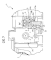
- FIGS. 6 and 7 are sections taken on the lines VI-VI and VII-VII respectively of FIG. 5 .
- an integrated dispenser device according to the invention is generally indicated 1 and is intended to be fitted to the inside surface of the front door of a dishwasher.
- the door of a dishwasher is usually hinged to the body of the machine along its bottom edge and can be opened into a substantially horizontal position (loading position) in order to place utensils needing washing in the washing chamber or to remove them after washing, and a vertical position (working position) in which the door closes the washing chamber, preventing any liquid from escaping during operation.
- the integrated dispenser device 1 fitted to the door of a dishwasher is therefore also moved in operation between a horizontal loading position, in which it can be filled with detergent and rinse agent, and a vertical working position, in which the device faces into the washing chamber and is operable to dispense detergent and rinse agent, during the wash and rinse cycles respectively.
- detergent or washing agent should be understood to mean any type of detergent or soap used in a dishwashing cycle.
- rinse agent should be understood to mean any product that can be used to improve the shine on clean items.
- the integrated dispenser device 1 includes an elongate body 2 of a plastics material, to be fitted into a corresponding aperture provided in the door of a dishwasher.
- the body 2 can be made in two parts for example, a main or front portion and an auxiliary or rear portion respectively, both produced by injection moulding and then connected together and heat welded using a hot blade device.
- a receptacle 5 for containing a quantity of detergent is formed in the front surface 3 of the body 2 which will face towards the washing chamber of the dishwasher.
- a lid 6 is pivoted on the body 2 , with a seal 7 fixed to its inside surface, for sealing the detergent receptacle 5 when the lid 6 is in the closed position shown by the broken line in FIG. 1 .
- the lid 6 has an associated spring urging it into its open position, illustrated by a solid line in FIG. 1 .
- a rocker 8 is mounted for rotation on the front portion of the body 2 , adjacent the receptacle 5 , its two arms ending in hook members 9 operable to engage corresponding retaining members 10 provided in the lid 6 for holding it in its closed position.
- the rocker 8 is mounted for rotation on a shaft 11 which passes through the body 2 , projecting from the back of it, as seen for example in FIG. 2 .
- a dispenser for a rinse agent is incorporated into the body 2 next to the detergent dispenser device 5 , 6 .
- this device includes an essentially cylindrical seat 12 , formed in the front portion of the body 2 , with a rotatable dispenser device, generally indicated 13 , arranged therein.
- the rinse agent dispenser 4 includes a dispenser chamber 14 with a delivery aperture 16 formed in its bottom surface 15 with an associated movable shutter 17 .
- This shutter 17 is essentially tubular in shape, with a closed lower end which forms the shutter itself.
- a control rod 18 is force fitted into the tubular shutter, the upper end 18 a thereof protruding upwardly into the rear portion of the body 2 of the integrated dispenser device, as shown for example in FIG. 2 .
- the aperture 16 opens into an underlying duct 19 intended for conveying the rinse agent into the washing chamber of the dishwasher (see also FIG. 1 ).
- an electromagnetic actuator or electromagnet 20 is mounted in the area between the detergent receptacle 5 and the rinse agent dispenser 4 , with a movable core 21 projecting from the bottom.
- the lower end 21 a of the core 21 is operatively coupled to a lever carried 22 by the shaft 11 .
- the distal end of the lever 22 has a shaped formation 22 a with an upper projection 22 b from which a stop projection 22 c projects transversely (in the direction of the observer in FIG. 2 ) (see also FIG. 6 ), the function of which will be described later.
- the formation 22 a has a recess or cavity 22 d , the bottom wall of which is indicated 22 e .
- the upper, or upwardly facing portion of this wall 22 e has a vertically elongate through aperture 22 f.
- an interconnecting element linking the lever 22 and the control member 18 of the shutter 17 of the rinse agent dispenser 4 is generally indicated 23 .
- the interconnecting element 23 is in the shape of a right-angled triangle. This shape is not compulsory however.
- an arm 23 a projects from the surface thereof facing the body of the dispenser device 1 and is snap engaged in a passage 18 b in a shaped formation 18 c on the rod 18 , near its end 18 a (see FIGS. 6 and 7 ).
- the shaped formation 18 c has opposite terminal extensions 18 d and 18 e , slidably engaged in respective grooves 24 and 25 in the body 2 in such a way that the rod 18 can translate parallel to its longitudinal axis but is prevented from rotating about this axis.
- the transverse passage 18 d in the formation 18 a on the rod 18 is such that when the projection or arm 23 a of the interconnecting element 23 is held therein it is able to oscillate both about the longitudinal axis of the rod 18 and about a transverse axis, indicated A-A in FIG. 7 .
- the longer side forming the right angle of the interconnecting element 23 has a rientrant portion 23 b whereby it rests against the stop projection 22 c on the lever 22 under the force of gravity.
- the centre of gravity of the interconnecting element 23 is spaced by a distance d from the vertical plane B-B containing the axis about which the interconnecting element 23 pivots about the control rod 18 of the rinse aid device dispenser 4 .
- the interconnecting element 23 therefore tends naturally to pivot, anticlockwise as viewed looking at FIG. 2 , and bear against the stop 22 c on the control arm 22 .
- a transverse projection or pin, indicated 26 in FIGS. 2 to 6 extends from the surface of the element 23 facing the body 2 of the integrated dispenser 1 , at the corner formed by the longer side and the hypotenuse.
- the dispenser device described above operates substantially in the manner which will be described next with reference to FIGS. 2 to 6 .
- the dispenser device 1 moves into the position illustrated in FIG. 2 : gravity causes the interconnecting element 23 to bear against the stop 22 c , with its feeler pin 26 against the side surface of the control lever 22 outside the recess 22 e and the through hole 22 f.
- the control unit of the appliance excites the electromagnetic actuator 20 for a first time.
- the core 21 thereof is “sucked” upwards, causing the control lever 22 and the associated shaft 11 to pivot from the position shown in FIG. 2 to the position shown in FIG. 3 .
- This pivoting of the shaft 11 causes a corresponding pivoting of the rocker 8 resulting in the lid 6 being released and, under the action of the associated resilient means, moving into the position shown in FIG. 1 , thereby opening the receptacle 5 and allowing the detergent contained therein to fall into the washing chamber.
- the device moves from the condition shown in FIG. 3 to that shown in FIG. 4 .
- the movable core 21 of the electromagnetic actuator 20 moves back into its initial position, thereby returning the lever 22 and the shaft 11 to their starting positions.
- the rotation of the lever 22 from the position of FIG. 3 to that of FIG. 4 causes the feeler pin 26 of the interconnecting element 23 to be positioned facing the aperture 22 f in the terminal formation 22 a of the lever 22 and to drop by gravity into this aperture. Since the pin 26 is held in the aperture 22 f , the interconnecting element 23 remains spaced from the stop projection 22 c.
- the control unit of the appliance excites the electromagnetic actuator 20 for a second time, causing the dispenser device 1 to move from the condition shown in FIG. 4 to that shown in FIG. 5 .
- the control lever 22 rotates anti-clockwise, and after rotating freely at first the lower edge of the aperture 22 f encounters the feeler pin 26 , moving it and the entire interconnecting element 23 upwards, causing a corresponding upward movement of the control rod 18 associated with the shutter 17 .
- This shift causes the end portion of the shutter 17 to move away from the associated aperture or seat 16 , allowing the rinse agent to flow from the dispenser chamber 14 into the delivery duct 19 .
- the electromagnetic actuator 20 is again de-energized and the dispenser device 1 as a whole returns to the condition shown in FIG. 4 .
- the dispenser device 1 As the wash cycle continues, it is possible to dispense additional doses of rinse agent, by re-energizing the electromagnetic actuator 20 and causing the dispenser device 1 to move once again from the condition of FIG. 4 to that shown in FIG. 5 .
- the interconnecting element 23 disengages again under the effect of gravity from the shaped terminal formation 22 a of the control lever 22 .
- control lever 22 and the interconnecting element 23 together form a transmission mechanism linking the electromagnetic actuator 20 and the rinse agent dispenser 4 , and that this mechanism becomes inoperative when the door of the appliance is opened, returning to its operating condition after the actuator device is first excited upon closing the door and then remaining inoperative for as long as the door remains closed.
- the electromagnetic actuator 20 is conveniently arranged between the receptacle 5 for the detergent or washing agent and the rinse agent dispenser 4 .
- the transmission mechanism between the electromagnetic actuator 20 and the rinse agent dispenser 4 is made simpler, since it has no two-arm lever, such as those of the prior art devices.
Landscapes
- Washing And Drying Of Tableware (AREA)
Applications Claiming Priority (4)
| Application Number | Priority Date | Filing Date | Title |
|---|---|---|---|
| ITTO2004A000226 | 2004-04-13 | ||
| ITTO2004A0226 | 2004-04-13 | ||
| IT000226A ITTO20040226A1 (it) | 2004-04-13 | 2004-04-13 | Dispositivo integrato di erogazione di agenti di lavaggio, particolarmente per macchine lavastoviglie |
| PCT/EP2005/051604 WO2005099553A2 (en) | 2004-04-13 | 2005-04-12 | An integrated washing agent dispenser, in particular for a dishwasher |
Publications (2)
| Publication Number | Publication Date |
|---|---|
| US20070215653A1 US20070215653A1 (en) | 2007-09-20 |
| US7721917B2 true US7721917B2 (en) | 2010-05-25 |
Family
ID=34964530
Family Applications (1)
| Application Number | Title | Priority Date | Filing Date |
|---|---|---|---|
| US10/599,891 Expired - Fee Related US7721917B2 (en) | 2004-04-13 | 2005-04-12 | Integrated washing agent dispenser, in particular for a dishwasher |
Country Status (10)
| Country | Link |
|---|---|
| US (1) | US7721917B2 (pl) |
| EP (1) | EP1740082B1 (pl) |
| CN (1) | CN100581435C (pl) |
| AU (1) | AU2005232403B2 (pl) |
| CA (1) | CA2562601C (pl) |
| DE (1) | DE602005008033D1 (pl) |
| ES (1) | ES2310347T3 (pl) |
| IT (1) | ITTO20040226A1 (pl) |
| PL (1) | PL1740082T3 (pl) |
| WO (1) | WO2005099553A2 (pl) |
Cited By (2)
| Publication number | Priority date | Publication date | Assignee | Title |
|---|---|---|---|---|
| US20090145922A1 (en) * | 2005-08-05 | 2009-06-11 | Eltek S.P.A. | Washing Agent Dispenser For A Household Washing Machine, In Particular a Dishwasher |
| US8881748B2 (en) | 2012-12-18 | 2014-11-11 | Whirlpool Corporation | Dishwasher detergent dispenser |
Families Citing this family (15)
| Publication number | Priority date | Publication date | Assignee | Title |
|---|---|---|---|---|
| US7699063B2 (en) * | 2005-08-18 | 2010-04-20 | Maytag Corporation | Dispenser for a drawer-type dishwasher |
| ES2385760A1 (es) * | 2009-08-21 | 2012-07-31 | BSH Electrodomésticos España S.A. | Maquina lavavajillas con dispositivo de sujeción de puerta. |
| PL221673B1 (pl) * | 2011-12-20 | 2016-05-31 | Bitron Poland Spółka Z Ograniczoną Odpowiedzialnością | Elektrycznie sterowane urządzenie uruchamiające i urządzenie dozujące |
| PL227509B1 (pl) | 2013-11-26 | 2017-12-29 | Bitron Poland Spółka Z Ograniczoną Odpowiedzialnością | Zintegrowany dozownik środka do mycia, w szczególności dla zmywarki do naczyń |
| PL227422B1 (pl) * | 2014-12-12 | 2017-11-30 | Bitron Poland Spółka Z Ograniczoną Odpowiedzialnością | Urzadzenie do dozowania srodka myjacego i srodka płuczacego, szczególnie do zmywarki do naczyn |
| IT201600121779A1 (it) * | 2016-12-01 | 2018-06-01 | Elbi Int Spa | Erogatore di agente di lavaggio per una macchina lavatrice, in particolare una lavastoviglie. |
| DE102016125845A1 (de) * | 2016-12-29 | 2018-07-05 | Sanhua Aweco Appliance Systems Gmbh | Vorrichtung zur Abgabe von Reinigungsmitteln |
| IT201700025267A1 (it) * | 2017-03-07 | 2018-09-07 | Elbi Int Spa | Gruppo per l'erogazione di agenti di lavaggio per una macchina lavatrice, in particolare una macchina lavastoviglie. |
| PL423109A1 (pl) * | 2017-10-09 | 2019-04-23 | Bitron Poland Spolka Z Ograniczona Odpowiedzialnoscia | Urządzenie dozujące środek myjący, w szczególności do zmywarki do naczyń |
| CN108742457A (zh) * | 2018-05-14 | 2018-11-06 | 佛山市顺德区美的洗涤电器制造有限公司 | 洗碗机分配器识别方法、装置及计算机可读存储介质 |
| CN108498049B (zh) * | 2018-06-07 | 2023-12-26 | 中山市富迪电器有限公司 | 洗碗机分配器 |
| PL239196B1 (pl) | 2018-12-31 | 2021-11-15 | Bitron Poland Spolka Z Ograniczona Odpowiedzialnoscia | Siłownik do domowego urządzenia elektrycznego |
| CN113576366B (zh) * | 2020-04-30 | 2025-11-18 | 三花亚威科电器设备(芜湖)有限公司 | 一种分配器和具有该分配器的洗碗机 |
| USD1020138S1 (en) * | 2021-08-31 | 2024-03-26 | Foshan Shunde Midea Washing Appliances Manufacturing Co., Ltd. | Automatic detergent dispenser for dishwasher |
| CN119816235A (zh) * | 2022-11-04 | 2025-04-11 | 三星电子株式会社 | 洗碗机 |
Citations (5)
| Publication number | Priority date | Publication date | Assignee | Title |
|---|---|---|---|---|
| US3827600A (en) * | 1972-01-10 | 1974-08-06 | Whirlpool Co | Apparatus for dispensing a liquid and another material |
| DE3304037A1 (de) | 1983-01-10 | 1984-07-12 | Aweco Apparate- und Gerätebau GmbH & Co KG, 7995 Neukirch | Vorrichtung fuer die zugabe bzw. dosierung von zwei detergentien |
| US5133487A (en) * | 1990-05-17 | 1992-07-28 | Giannino Sandrin | Dispenser for storing and dispensing fluent materials |
| DE19535153A1 (de) | 1995-09-21 | 1997-03-27 | Elbi Int Spa | Vorrichtung zur Einspeisung von Spülmitteln für Geschirrspülmaschinen |
| US7047987B2 (en) * | 2000-03-29 | 2006-05-23 | Eltek, S.P.A. | Washing agent dispensing device for a household washing machine, in particular a dishwasher |
Family Cites Families (3)
| Publication number | Priority date | Publication date | Assignee | Title |
|---|---|---|---|---|
| DE3304837A1 (de) * | 1983-02-09 | 1984-08-09 | Siemens AG, 1000 Berlin und 8000 München | Erdungsbuegel fuer einen stecker |
| EP1088927A1 (en) * | 1999-10-01 | 2001-04-04 | The Procter & Gamble Company | A smart dosing device |
| CN2503839Y (zh) * | 2001-09-21 | 2002-08-07 | 邱令洪 | 吸盘升降胀管适形旋刷型全自动洗碗机 |
-
2004
- 2004-04-13 IT IT000226A patent/ITTO20040226A1/it unknown
-
2005
- 2005-04-12 US US10/599,891 patent/US7721917B2/en not_active Expired - Fee Related
- 2005-04-12 WO PCT/EP2005/051604 patent/WO2005099553A2/en not_active Ceased
- 2005-04-12 CN CN200580011250A patent/CN100581435C/zh not_active Expired - Fee Related
- 2005-04-12 PL PL05733452T patent/PL1740082T3/pl unknown
- 2005-04-12 EP EP05733452A patent/EP1740082B1/en not_active Expired - Lifetime
- 2005-04-12 CA CA2562601A patent/CA2562601C/en not_active Expired - Fee Related
- 2005-04-12 AU AU2005232403A patent/AU2005232403B2/en not_active Ceased
- 2005-04-12 ES ES05733452T patent/ES2310347T3/es not_active Expired - Lifetime
- 2005-04-12 DE DE602005008033T patent/DE602005008033D1/de not_active Expired - Lifetime
Patent Citations (5)
| Publication number | Priority date | Publication date | Assignee | Title |
|---|---|---|---|---|
| US3827600A (en) * | 1972-01-10 | 1974-08-06 | Whirlpool Co | Apparatus for dispensing a liquid and another material |
| DE3304037A1 (de) | 1983-01-10 | 1984-07-12 | Aweco Apparate- und Gerätebau GmbH & Co KG, 7995 Neukirch | Vorrichtung fuer die zugabe bzw. dosierung von zwei detergentien |
| US5133487A (en) * | 1990-05-17 | 1992-07-28 | Giannino Sandrin | Dispenser for storing and dispensing fluent materials |
| DE19535153A1 (de) | 1995-09-21 | 1997-03-27 | Elbi Int Spa | Vorrichtung zur Einspeisung von Spülmitteln für Geschirrspülmaschinen |
| US7047987B2 (en) * | 2000-03-29 | 2006-05-23 | Eltek, S.P.A. | Washing agent dispensing device for a household washing machine, in particular a dishwasher |
Cited By (4)
| Publication number | Priority date | Publication date | Assignee | Title |
|---|---|---|---|---|
| US20090145922A1 (en) * | 2005-08-05 | 2009-06-11 | Eltek S.P.A. | Washing Agent Dispenser For A Household Washing Machine, In Particular a Dishwasher |
| US7934623B2 (en) * | 2005-08-05 | 2011-05-03 | Eltek S.P.A. | Washing agent dispenser for a household washing machine, in particular a dishwasher |
| US8881748B2 (en) | 2012-12-18 | 2014-11-11 | Whirlpool Corporation | Dishwasher detergent dispenser |
| US9795274B2 (en) | 2012-12-18 | 2017-10-24 | Whirlpool Corporation | Dishwasher detergent dispensing method |
Also Published As
| Publication number | Publication date |
|---|---|
| PL1740082T3 (pl) | 2008-12-31 |
| DE602005008033D1 (de) | 2008-08-21 |
| EP1740082B1 (en) | 2008-07-09 |
| EP1740082A2 (en) | 2007-01-10 |
| CA2562601C (en) | 2012-09-11 |
| CA2562601A1 (en) | 2005-10-27 |
| WO2005099553A2 (en) | 2005-10-27 |
| ES2310347T3 (es) | 2009-01-01 |
| US20070215653A1 (en) | 2007-09-20 |
| WO2005099553A3 (en) | 2007-07-19 |
| ITTO20040226A1 (it) | 2004-07-13 |
| AU2005232403B2 (en) | 2010-12-09 |
| CN101083933A (zh) | 2007-12-05 |
| CN100581435C (zh) | 2010-01-20 |
| AU2005232403A1 (en) | 2005-10-27 |
Similar Documents
| Publication | Publication Date | Title |
|---|---|---|
| US7721917B2 (en) | Integrated washing agent dispenser, in particular for a dishwasher | |
| US10238267B2 (en) | Integrated washing agent dispenser, in particular for a dishwasher | |
| US7063092B2 (en) | Washing agent dispensing device for a household washing machine, in particular a dishwasher | |
| US10441130B2 (en) | Washing and rinsing agents dispensing device, particularly for a dishwasher machine | |
| US7832417B2 (en) | Dispenser for a drawer-type dishwasher | |
| EP1450661B1 (en) | Dispenser device particularly for dishwashing machines | |
| EP1226779A2 (en) | Washing agents dispenser for a household washing machine, namely a dishwasher | |
| EP1281346A1 (en) | Domestic dishwasher with a front door and a detergent measurer which can be refilled on the top of the door | |
| PL230510B1 (pl) | Urzadzenie dozujace srodek myjacy dla zmywarki do naczyn | |
| EP1455631B1 (en) | A dispenser of washing agents for a household washing machine, in particular a dish-washer | |
| EP1610663B1 (en) | Washing machine with a dispenser for a diversified dispensing of washing agents, and a device and method for implementation thereof | |
| PL223690B1 (pl) | Zintegrowane urządzenie do dozowania środków myjących do maszyny myjącej, zwłaszcza do zmywarki do naczyń | |
| ITTO940997A1 (it) | Dispositivo per l'erogazione di detersivo e di un agente di risciac- quo di una macchina avastoviglie | |
| CN110913742B (zh) | 用于用来洗涤的家用机器尤其是洗碗机的洗涤剂分配器 | |
| EP2918215A1 (en) | Detergent dispenser for dishwasher | |
| CN108601501B (zh) | 用于分配洗涤剂的装置 | |
| CA2551977A1 (en) | Dispenser for a drawer-type dishwasher | |
| JP3608946B2 (ja) | キャニスタにおけるシャッタ軸の抜け止め構造 | |
| CN116744830A (zh) | 洗碗机 | |
| ITTO940414A1 (it) | Dispositivo per l'erogazione di agenti di lavaggio per macchine lavastoviglie. | |
| IT9045742A1 (it) | Dispensatore di sostanze liquide ed in polvere per macchine lavatrici | |
| JPH04141124A (ja) | 食器洗い機の処理剤投入装置 |
Legal Events
| Date | Code | Title | Description |
|---|---|---|---|
| AS | Assignment |
Owner name: ELBI INTERNATIONAL S.P.A.,ITALY Free format text: ASSIGNMENT OF ASSIGNORS INTEREST;ASSIGNOR:MARONE, GIUSEPPE;REEL/FRAME:018384/0428 Effective date: 20060713 Owner name: ELBI INTERNATIONAL S.P.A., ITALY Free format text: ASSIGNMENT OF ASSIGNORS INTEREST;ASSIGNOR:MARONE, GIUSEPPE;REEL/FRAME:018384/0428 Effective date: 20060713 |
|
| STCF | Information on status: patent grant |
Free format text: PATENTED CASE |
|
| FPAY | Fee payment |
Year of fee payment: 4 |
|
| MAFP | Maintenance fee payment |
Free format text: PAYMENT OF MAINTENANCE FEE, 8TH YEAR, LARGE ENTITY (ORIGINAL EVENT CODE: M1552) Year of fee payment: 8 |
|
| FEPP | Fee payment procedure |
Free format text: MAINTENANCE FEE REMINDER MAILED (ORIGINAL EVENT CODE: REM.); ENTITY STATUS OF PATENT OWNER: LARGE ENTITY |
|
| LAPS | Lapse for failure to pay maintenance fees |
Free format text: PATENT EXPIRED FOR FAILURE TO PAY MAINTENANCE FEES (ORIGINAL EVENT CODE: EXP.); ENTITY STATUS OF PATENT OWNER: LARGE ENTITY |
|
| STCH | Information on status: patent discontinuation |
Free format text: PATENT EXPIRED DUE TO NONPAYMENT OF MAINTENANCE FEES UNDER 37 CFR 1.362 |
|
| STCH | Information on status: patent discontinuation |
Free format text: PATENT EXPIRED DUE TO NONPAYMENT OF MAINTENANCE FEES UNDER 37 CFR 1.362 |
|
| FP | Lapsed due to failure to pay maintenance fee |
Effective date: 20220525 |