US875142A - Hose-supporter clasp. - Google Patents
Hose-supporter clasp. Download PDFInfo
- Publication number
- US875142A US875142A US23490604A US1904234906A US875142A US 875142 A US875142 A US 875142A US 23490604 A US23490604 A US 23490604A US 1904234906 A US1904234906 A US 1904234906A US 875142 A US875142 A US 875142A
- Authority
- US
- United States
- Prior art keywords
- button
- loop
- head
- clasp
- rubber
- Prior art date
- Legal status (The legal status is an assumption and is not a legal conclusion. Google has not performed a legal analysis and makes no representation as to the accuracy of the status listed.)
- Expired - Lifetime
Links
- 239000004744 fabric Substances 0.000 description 10
- 230000003014 reinforcing effect Effects 0.000 description 6
- 239000000463 material Substances 0.000 description 5
- 239000002184 metal Substances 0.000 description 3
- 230000006872 improvement Effects 0.000 description 2
- 230000004048 modification Effects 0.000 description 2
- 238000012986 modification Methods 0.000 description 2
- 230000002787 reinforcement Effects 0.000 description 2
- 230000009471 action Effects 0.000 description 1
- 230000008901 benefit Effects 0.000 description 1
- 238000010276 construction Methods 0.000 description 1
- 238000006073 displacement reaction Methods 0.000 description 1
- 238000003780 insertion Methods 0.000 description 1
- 230000037431 insertion Effects 0.000 description 1
- 239000007779 soft material Substances 0.000 description 1
Images
Classifications
-
- A—HUMAN NECESSITIES
- A41—WEARING APPAREL
- A41F—GARMENT FASTENINGS; SUSPENDERS
- A41F11/00—Stocking or sock suspenders
- A41F11/02—Devices for attaching the stocking or sock to the suspender
- A41F11/04—Devices for attaching the stocking or sock to the suspender of the stud-and-loop type
-
- Y—GENERAL TAGGING OF NEW TECHNOLOGICAL DEVELOPMENTS; GENERAL TAGGING OF CROSS-SECTIONAL TECHNOLOGIES SPANNING OVER SEVERAL SECTIONS OF THE IPC; TECHNICAL SUBJECTS COVERED BY FORMER USPC CROSS-REFERENCE ART COLLECTIONS [XRACs] AND DIGESTS
- Y10—TECHNICAL SUBJECTS COVERED BY FORMER USPC
- Y10T—TECHNICAL SUBJECTS COVERED BY FORMER US CLASSIFICATION
- Y10T24/00—Buckles, buttons, clasps, etc.
- Y10T24/44—Clasp, clip, support-clamp, or required component thereof
- Y10T24/44077—Clasp, clip, support-clamp, or required component thereof having inserted and receiving interlocking members connected by bendable, nonbiasing strap
- Y10T24/44085—Discrete flaccid strap
- Y10T24/44128—Resilient inserted or receiving member
- Y10T24/44145—Resilient inserted member
- Y10T24/44154—Resilient inserted member having engaging face formed from nonmetallic material
- Y10T24/44162—Resilient inserted member having engaging face formed from nonmetallic material having head and neck type engaging face
- Y10T24/44171—Resilient inserted member having engaging face formed from nonmetallic material having head and neck type engaging face having internal supporting or reinforcing element
- Y10T24/44179—Circular head or neck
Definitions
- This invention relates to button and loop fasteners as exemplified in Gorton Patent No. 552,470, of Dec. 31, 1895. its object is to produce an improved fastener of this type which shall be simple of construction and at the same time absolutely reliable in action, neat in appearance, and applicable alike to mns and womens garters.
- the invention comprises in. combination with a loop member a cooperating member consisting essentially of homogeneous mass of flexible yielding material exemplified by rubber having a button portion the head at least of which is provided with a rigid or relatively rigid body or reinforcement which preeludes the possibility of the button being drawn through the loop by the yielding of its head portion.
- a button head or body which cannot be drawn through the loop when in place, is cushioned against the loop, and at the same time flexibly secured to the other portions of the supporter by the yielding and flexible material of the plate.
- Figure 1 shows in front view the invention in one preferred form, the button F being out of and behind the loop ready for inserting the fabric.
- Fig. 2 shows the metal blank from which the loop is made.
- Fig. 3 is a rear view of the clasp.
- Fig. 4 is a face view of the button and back plate.
- Fig. 5 is a central longitudinal section of Fig. 4.
- Fig. 6 shows the knotted and concealed end of the cord D of Fig. 1; and
- Fig. 7 shows a modification of the button and back plate.
- leg band B and cord D details not essential to the present invention, D being preferably of elastic cord and the band B being preferably of relatively nonelastic material as patented in the Nealon do Binney Patent No. 603,430 of ll iay 3, 1898.
- C is the metallic loop which for the purposes of the present invention may be of any suitable form to cooperate with the button.
- the baclu" plate G is preferably of the same comparatively soft rubber composition as the button and molded integrally with the button but is faced on the rear as n (Figs. 5 and 7) with fabric so as to roll the rubber while permitting it to be thin consequently very fie; 'ble without resilie in Figs. 3, i, and 5 metallic body of s like form, S, S is shown embedded molded within the rubber button. front end S of this stud-like body is within the head of the button F and serves to prevent the possibility of the head being drawn through the loop under strain.
- the sh n and the plate S of the stud-like be y within the button may be employed to internal support to the entire button anc.
- a modification is shown wherein. a metallic disk S is embedded in. the head only of the button F and located transversely of its longitudinal axis.
- the button becomes indistin guishable in, appearance from an all-rubber button, while nevertheless having the functions of a rigid stud surrounded by rubber and of therefore standing greater strains than would be possible with the pure soft rubber, so as to enable women to use this desirable form of the fastener without any fear of their I hosiery slouching about their heels and withhose and at the same time by reason theout any uncertainty of operation.
- this interiorly rigid feature is the cause of preventing the head from collapsing and being drawn through.
- the invention is distinguished from Phelps Patent 538,383, in addition to other differ.
- the reinforcing plate or portion within the head of the button is of su icient diameter to prevent the button F being drawn through the lower part of the loo (3. While it may be a little larger or a litt e smaller than the width of the loop, it is advantageously approximately equal thereto.
- said embraced member comprising an integral yielding button head, shank and base, a relatively rigid reinforcement located wholly within said head.
- a reinforcing plate within the head of the button portion of the said first named member and disposed transversely of its longitudinal axis.
- a relatively rigid reinforcing portion located entirely within the head of said button for increasing its resist ance to lateral displacement.
- a loop In a hose supporter clasp, a loop, a rigid disk for cooperating therewith as a button or button head, and a back plate member of yielding material having an extension which extends through the loop and encircles,cushions and holds said disk.
- a clasp or fastener of the type having a yielding button member and an embracing external member for embracing a fabric against the button member
Landscapes
- Engineering & Computer Science (AREA)
- Textile Engineering (AREA)
- Details Of Garments (AREA)
Description
'No. 375,142. PATENTED DEC. 31, 1907.
. H. BINNBY. HOSE SUPPORTER CLASP.
APPLICATION TILED NOV. 30, 1904.
l-Ublll @TA'TFQS F OFFIGFL HAROLD BINNEY, OF NEW YORK, N. Y., ASSIGNOR TO NEALON COMPANY, A CORPORATION OF NEW YORK.
HOSE-SUPPORTER no. arenas.
Specification of Letters Patent.
Patented Dec. 31,
To all whom it may concern:
Be it known that l, l'iAROLD BINNEY, of the city of New York, post-office address 10 Lexington avenue, New York city, New York, have invented certain new and useful Improvements in Hose-Supporter Clasps, of which the following is a specification.
This invention relates to button and loop fasteners as exemplified in Gorton Patent No. 552,470, of Dec. 31, 1895. its object is to produce an improved fastener of this type which shall be simple of construction and at the same time absolutely reliable in action, neat in appearance, and applicable alike to mns and womens garters.
The invention comprises in. combination with a loop member a cooperating member consisting essentially of homogeneous mass of flexible yielding material exemplified by rubber having a button portion the head at least of which is provided with a rigid or relatively rigid body or reinforcement which preeludes the possibility of the button being drawn through the loop by the yielding of its head portion. Thus is provided for the first time a button head or body which cannot be drawn through the loop when in place, is cushioned against the loop, and at the same time flexibly secured to the other portions of the supporter by the yielding and flexible material of the plate.
The accompanying drawings illustrate also another improvement in the metal parts of the clasp which forms the subject-matter of my separate application filed November 30th, 1904 Serial l lo. 234,907 and also show the combination of the button with a rubber or other similar backing secured directly to the clasp, thus utilizing the flexibility of the U backing to permit the insertion of the stocking and doing away with any need of a hinge between stud and loop, or between the loop and the webbing.
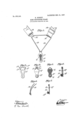
In the drawings, Figure 1 shows in front view the invention in one preferred form, the button F being out of and behind the loop ready for inserting the fabric. Fig. 2 shows the metal blank from which the loop is made. Fig. 3 is a rear view of the clasp. Fig. 4 is a face view of the button and back plate. Fig. 5 is a central longitudinal section of Fig. 4. Fig. 6 shows the knotted and concealed end of the cord D of Fig. 1; and Fig. 7 shows a modification of the button and back plate.
in Fig. l the leg band B and cord D details not essential to the present invention, D being preferably of elastic cord and the band B being preferably of relatively nonelastic material as patented in the Nealon do Binney Patent No. 603,430 of ll iay 3, 1898.
C is the metallic loop which for the purposes of the present invention may be of any suitable form to cooperate with the button.
is the bu ton and G its bacl plate. The baclu". plate G is preferably of the same comparatively soft rubber composition as the button and molded integrally with the button but is faced on the rear as n (Figs. 5 and 7) with fabric so as to roll the rubber while permitting it to be thin consequently very fie; 'ble without resilie in Figs. 3, i, and 5 metallic body of s like form, S, S is shown embedded molded within the rubber button. front end S of this stud-like body is within the head of the button F and serves to prevent the possibility of the head being drawn through the loop under strain. The sh n and the plate S of the stud-like be y within the button may be employed to internal support to the entire button anc. it is the principle ofnperation of such buttons that they are to float freely it were, or in other words, travels up and down with the movements of the fabric in the loop, the back plate Gr servin merely as a means of attachment and not as a means of sustaining y pull of thehose, it follows that such a button as shown in Figs. 3, i, and is particularly well adapted to the purpose of securing the new flexibility of the bacl plate G it be conveniently attached and detached from the hose. I
in Fig. 7 a modification is shown wherein. a metallic disk S is embedded in. the head only of the button F and located transversely of its longitudinal axis. As the disk S in this form of the invention is entirely covered by the rubber, the button becomes indistin guishable in, appearance from an all-rubber button, while nevertheless having the functions of a rigid stud surrounded by rubber and of therefore standing greater strains than would be possible with the pure soft rubber, so as to enable women to use this desirable form of the fastener without any fear of their I hosiery slouching about their heels and withhose and at the same time by reason theout any uncertainty of operation. It will be seen that this interiorly rigid feature is the cause of preventing the head from collapsing and being drawn through.
The invention is distinguished from Phelps Patent 538,383, in addition to other differ.
. enlarged ences, by having an interior reinforce in the portion or head of the button.
It will be noted that the reinforcing plate or portion within the head of the button is of su icient diameter to prevent the button F being drawn through the lower part of the loo (3. While it may be a little larger or a litt e smaller than the width of the loop, it is advantageously approximately equal thereto.
The back plate G is preferably directly secured to the clasp so that the mere flexibility of the rubber G is relied upon to permit the clasp opening to insert and withdraw the fabric of the garment, there being no hinge between the loop and the back plate. For this same reason it is desirable that the back-plate be very flexible and it may therefore with advantage be corrugated horizontally so as to permit it readily p to .bend to insert and withdraw the stud and to prevent its being at all stiff and resilient or having any tendency to push or pull on the stud when in the loop. This flexibility is preferably made very great and the'backing of fabric Gt while tending to prevent any resilience or elasticity also toughens the back piece as is well known to thosefamiliar with this type of garter, wherein it has been quite common to back the rubber with a non-resilient fabric.
r rubber covered metal stud by The transverse corrugation of the rubber as described will of course minimize any tendency to longitudinal stiffness and is distinguished wide y in this respect from. the
prior invention set forth in Phelps Patent The object of the rubber back plate G in the present invention is to form the direct and immediate attachment of the button to the metallic parts.
It will be seen that I make no claim to a itself, so also I make no claim to combining in a single member or element.a button and a backn plate, but
said embraced member comprising an integral yielding button head, shank and base, a relatively rigid reinforcement located wholly within said head.
2. In a clasp or fastener of thetype having .an integral yielding button and back member and an embracing external member between which members the fabric is engaged, a reinforcing plate within the head of the button portion of the said first named member and disposed transversely of its longitudinal axis.
3. In aclasp or fastener of the type having a yielding button member and an embracing external member between which members the fabric is engaged, a relatively rigid reinforcing portion located entirely within the head of said button for increasing its resist ance to lateral displacement.
4. In a clasp or fastener of the type having an integral yielding button and back member and an embracing external member provided with a loop portion, the fabric is engaged, a reinforcing plate located within the button portion of said firstnamed member, the diameter of said reinforcing plate being approximately equal to the width of the loop portion of said embrac ing member. p
5. In a hose supporter clasp, a loop, a rigid disk for cooperating therewith as a button or button head, and a back plate member of yielding material having an extension which extends through the loop and encircles,cushions and holds said disk.
6. In a clasp or fastener of the type having a yielding button member and an embracing external member for embracing a fabric against the button member, the combination of an embracing member and a combined integral back plate and button member of relatively soft and flexible material and a reinforcing head cushioned in the button member and secured thereto by a rivet or shank, the' said head and adjacent soft material being of too great size to pass through the embracing member and the said back plate being secured adjacent to the upper end of the said embracing member, for substantially the purposes 'set forth.
In testimony whereof I have signed this specification in the presence of two subscribing witnesses.
' HAROLD BINNEY. Witnesses:
E. VAN ZANDT, GEO. L. COOPER.
between which members
Priority Applications (1)
| Application Number | Priority Date | Filing Date | Title |
|---|---|---|---|
| US23490604A US875142A (en) | 1904-11-30 | 1904-11-30 | Hose-supporter clasp. |
Applications Claiming Priority (1)
| Application Number | Priority Date | Filing Date | Title |
|---|---|---|---|
| US23490604A US875142A (en) | 1904-11-30 | 1904-11-30 | Hose-supporter clasp. |
Publications (1)
| Publication Number | Publication Date |
|---|---|
| US875142A true US875142A (en) | 1907-12-31 |
Family
ID=2943586
Family Applications (1)
| Application Number | Title | Priority Date | Filing Date |
|---|---|---|---|
| US23490604A Expired - Lifetime US875142A (en) | 1904-11-30 | 1904-11-30 | Hose-supporter clasp. |
Country Status (1)
| Country | Link |
|---|---|
| US (1) | US875142A (en) |
Cited By (1)
| Publication number | Priority date | Publication date | Assignee | Title |
|---|---|---|---|---|
| US2857645A (en) * | 1955-01-04 | 1958-10-28 | Vogelsang Hedwig | Suspender |
-
1904
- 1904-11-30 US US23490604A patent/US875142A/en not_active Expired - Lifetime
Cited By (1)
| Publication number | Priority date | Publication date | Assignee | Title |
|---|---|---|---|---|
| US2857645A (en) * | 1955-01-04 | 1958-10-28 | Vogelsang Hedwig | Suspender |
Similar Documents
| Publication | Publication Date | Title |
|---|---|---|
| US1492403A (en) | Soft-collar attachment | |
| US875142A (en) | Hose-supporter clasp. | |
| US1266219A (en) | Garment-support. | |
| US664675A (en) | Suspenders. | |
| US936787A (en) | Trousers-supporter. | |
| US696912A (en) | Hose-supporter. | |
| US761956A (en) | Garment-supporter. | |
| US883475A (en) | Combined pocket and garment supporter. | |
| US1459750A (en) | Shirt retainer | |
| US623458A (en) | Adolph bernstein | |
| US852858A (en) | Jacob m | |
| US1370066A (en) | Garter | |
| US732378A (en) | Abdominal corset. | |
| US701333A (en) | Waistband. | |
| US705519A (en) | Hose-supporter. | |
| US1426635A (en) | Hose supporter | |
| US633583A (en) | Garment-supporter. | |
| US538383A (en) | Catch for stocking or garment supporters | |
| US449710A (en) | Frederick spitz | |
| US227479A (en) | Flexible center-button | |
| US688144A (en) | Waistband. | |
| US1390769A (en) | Hose-supporter | |
| US690666A (en) | Attaching button or stud. | |
| US939893A (en) | Corset. | |
| US1261960A (en) | Suspender-strap holder. |