WO1996029696A1 - Analysis-by-synthesis linear predictive speech coder - Google Patents
Analysis-by-synthesis linear predictive speech coder Download PDFInfo
- Publication number
- WO1996029696A1 WO1996029696A1 PCT/SE1996/000296 SE9600296W WO9629696A1 WO 1996029696 A1 WO1996029696 A1 WO 1996029696A1 SE 9600296 W SE9600296 W SE 9600296W WO 9629696 A1 WO9629696 A1 WO 9629696A1
- Authority
- WO
- WIPO (PCT)
- Prior art keywords
- excitation
- pulse
- bits
- code book
- bit
- Prior art date
- Legal status (The legal status is an assumption and is not a legal conclusion. Google has not performed a legal analysis and makes no representation as to the accuracy of the status listed.)
- Ceased
Links
Classifications
-
- G—PHYSICS
- G10—MUSICAL INSTRUMENTS; ACOUSTICS
- G10L—SPEECH ANALYSIS TECHNIQUES OR SPEECH SYNTHESIS; SPEECH RECOGNITION; SPEECH OR VOICE PROCESSING TECHNIQUES; SPEECH OR AUDIO CODING OR DECODING
- G10L13/00—Speech synthesis; Text to speech systems
-
- G—PHYSICS
- G10—MUSICAL INSTRUMENTS; ACOUSTICS
- G10L—SPEECH ANALYSIS TECHNIQUES OR SPEECH SYNTHESIS; SPEECH RECOGNITION; SPEECH OR VOICE PROCESSING TECHNIQUES; SPEECH OR AUDIO CODING OR DECODING
- G10L19/00—Speech or audio signals analysis-synthesis techniques for redundancy reduction, e.g. in vocoders; Coding or decoding of speech or audio signals, using source filter models or psychoacoustic analysis
- G10L19/04—Speech or audio signals analysis-synthesis techniques for redundancy reduction, e.g. in vocoders; Coding or decoding of speech or audio signals, using source filter models or psychoacoustic analysis using predictive techniques
- G10L19/08—Determination or coding of the excitation function; Determination or coding of the long-term prediction parameters
- G10L19/10—Determination or coding of the excitation function; Determination or coding of the long-term prediction parameters the excitation function being a multipulse excitation
-
- G—PHYSICS
- G10—MUSICAL INSTRUMENTS; ACOUSTICS
- G10L—SPEECH ANALYSIS TECHNIQUES OR SPEECH SYNTHESIS; SPEECH RECOGNITION; SPEECH OR VOICE PROCESSING TECHNIQUES; SPEECH OR AUDIO CODING OR DECODING
- G10L19/00—Speech or audio signals analysis-synthesis techniques for redundancy reduction, e.g. in vocoders; Coding or decoding of speech or audio signals, using source filter models or psychoacoustic analysis
- G10L19/04—Speech or audio signals analysis-synthesis techniques for redundancy reduction, e.g. in vocoders; Coding or decoding of speech or audio signals, using source filter models or psychoacoustic analysis using predictive techniques
- G10L19/06—Determination or coding of the spectral characteristics, e.g. of the short-term prediction coefficients
Definitions
- the present invention relates to an analysis-by-synthesis linear predictive speech coder.
- Such speech coders are used in e.g. cellular radio communication systems.
- An analysis-by-synthesis speech coder [1] consists of three main components in the synthesis part, namely a linear predictive coding (LPC) synthesis filter, an adaptive code book and some type of fixed excitation.
- LPC linear predictive coding
- the synthesis of the speech is done by filtering an excitation vector through the LPC synthesis filter to produce the synthetic speech signal.
- the excitation vector is formed by adding together scaled versions of vectors coming from the adaptive code book and the fixed excitation.
- the analysis part of an analysis-by-synthesis coder consists mainly of the LPC analysis and the excitation analysis.
- the excitation analysis is a search for the indices or other parameters for the excitation, e.g. indices for the code book, gain parameters for the excitation or the amplitudes and positions for excitation pulses.
- the used excitation structure in an analysis-by-synthesis speech coder is essential for the quality of the reconstructed speech, the complexity of the search and the robustness to bit errors.
- the excitation needs to be rich, i.e. contain both pulse-like and noise-like components.
- the excitation needs to be somewhat structured, due to the fact that the search for the excitation code tends to be of low complexity in a structured code book.
- the bit error sensitivity for the unprotected bits of the excitation code must be low.
- mixed excitation procedures have been proposed [2-8].
- the mix usually consists of pulse and noise sequences. Pulse-like excitations are needed in onsets, plosive and voiced sections of the speech. Noise-like sequences are needed for unvoiced sounds.
- Multi-pulse excitation has been described in [9] and consists of pulses described by a position and an amplitude.
- Regular pulse excitation RPE
- RPE Regular pulse excitation
- TBPE Transformed binary pulse excitation
- VSE Vector sum excitation
- VSE Vector sum excitation
- index assignment [15] and phase position coding [16] have been proposed.
- An object of the present invention is an analysis-by-synthesis linear predictive speech coder that provides both high quality (excitation richness), low search complexity and high robustness in a mobile radio environment.
- FIGURE 1 is a block diagram of a typical analysis-by-synthesis linear predictive speech coder
- FIGURE 2 illustrates the principles of multi-pulse excitation (MPE);
- FIGURE 3 illustrates a bit allocation scheme for a multi- pulse excitation
- FIGURE 4 is a diagram illustrating the bit error sensitivity of the multi-pulse excitation defined in Figure 3;
- FIGURE 5 a-e illustrates the principles of phase position coded multi-pulse excitation
- FIGURE 6a illustrates the principles of transformed binary pulse excitation (TBPE);
- FIGURE 6b illustrates TBPE for a special case of only two pulses
- FIGURE 7 illustrates a bit allocation scheme for a transformed binary pulse excitation
- FIGURE 8 is a diagram illustrating the bit error sensitivity of the transformed binary pulse excitation
- FIGURE 9 illustrates a bit allocation scheme for a combined multi-pulse and transformed binary pulse excitation in accordance with a preferred embodiment of the present invention
- FIGURE 10 is a diagram illustrating the bit error sensitivity of the combined multi-pulse and transformed binary pulse excitation in accordance with a preferred embodiment of the present invention
- FIGURE 11 compares the bit error sensitivities illustrated in
- FIGURE 12 is a block diagram of a preferred embodiment of a speech coder in accordance with the present invention. DETAILED DESCRIPTION OF THE PREFERRED EMBODIMENTS
- Fig. 1 shows a block diagram of a typical analysis-by-synthesis linear predictive speech coder.
- the coder comprises a synthesis part to the left of the vertical dashed center line and an analysis part to the right of said line.
- the synthesis part essentially includes two sections, namely an excitation code generating section 10 and an LPC synthesis filter 12.
- the excitation code generating section 10 comprises an adaptive code book 14, a fixed code book 16 and an adder 18.
- a chosen vector a-(n) from the adaptive code book 14 is multiplied by a gain factor g- for forming a signal p(n).
- an excitation vector from the fixed code book 16 is multiplied by a gain factor g- for forming a signal f(n).
- the signals p(n) and f(n) are added in adder 18 for forming an excitation vector ex(n), which excites the LPC synthesis filter 12 for forming an estimated speech signal vector .
- the estimated vector is subtracted from the actual speech signal vector s(n) in an adder 20 for forming an error signal e(n).
- This error signal is forwarded to a weighting filter 22 for forming a weighted error vector e w (n).
- the components of this weighted error vector are squared and summed in a unit 24 for forming a measure of the energy of the weighted error vector.
- a minimization unit 26 minimizes this weighted error vector by choosing that combination of gain g I and vector from the adaptive code book 14 and that gain g J and vector from the fixed code book 16 that gives the smallest energy value, that is which after filtering in filter 12 best approximates the speech signal vector s(n). This optimization is divided into two steps.
- the filter parameters of filter 12 are updated for each speech signal frame (160 samples) by analyzing the speech signal frame in a LPC analyzer 28. This updating has been marked by the dashed connection between analyzer 28 and filter 12. Furthermore, there is a delay element 30 between the output of adder 18 and the adaptive code book 14. In this way the adaptive code book 14 is updated by the finally chosen excitation vector ex(n) . This is done on a subframe basis, where each frame is divided into four subframes (40 samples).
- the used excitation structure of the fixed code book is essential for the quality of the reconstructed speech, the complexity of the search and the robustness to bit errors.
- the excitation needs to be rich, i.e. contain both pulse-like and noise-like components.
- the excitation needs to be somewhat structured.
- the search for the excitation code tends to be of relatively low complexity in a structured code book.
- the bit error sensitivity for the unprotected bits of the excitation code must be low. This is not as important for the protected (channel coded) bits of the excitation code.
- the bit error sensitivity in the excitation code should differ between protected and unprotected bits. Usually the unprotected class of bits will limit the performance in high BER channels.
- Multi-pulse excitation which is illustrated in Fig. 2, is known to provide high quality at higher bit rates. For example 6-8 pulses per 40 samples (or 5 milliseconds) is known to give good quality.
- Fig. 2 illustrates 6 pulses distributed over a subframe.
- the excitation vector may be described by the positions of these pulses (positions 7, 9, 14, 25, 29, 37 in the example) and the amplitudes of the pulses (AMP1-AMP6 in the example). Methods for finding these parameters are described in [9].
- AMP1-AMP6 amplitudes of the pulses
- Methods for finding these parameters are described in [9].
- the amplitudes only represent the shape of the excitation vector. Therefore a block gain is used to represent the amplification of this basic vector shape.
- FIG. 3 shows an example of the format of the bit distribution of a typical multi-pulse excitation consisting of six pulses.
- the bit error sensitivity of the multi-pulse excitation is known to be relatively high for some of the bits.
- Fig. 4 The figure illustrates the signal-to-noise ratio of reconstructed speech for 100% BER in each bit position of the excitation.
- each bit position in the format of Fig. 3 is individually set to the wrong value, while all other bit positions are correct.
- the reconstructed signal is compared to the original signal and the signal-to-noise ratio is computed.
- the length of each line in Fig. 4 represents the sensitivity of the reconstructed speech to an error in that bit position.
- high SNR indicates low bit error sensitivity.
- phase position coding [16]. This pulse position coding scheme has higher coding efficiency than a combinatorial scheme, but the trade off is somewhat lower speech quality.
- the principles of phase position coding are illustrated in Figs. 5a-e. In phase position coding the total number of positions are divided into a number of sub-blocks, 4 sub-blocks in the figure. Each sub-block contains a number of phases, ten phases in the figure. A restriction is imposed on the allowable pulse position. There is only one pulse allowed in each phase. This means that the positions can be coded by describing the phase positions and sub-block positions of the pulses. The phase positions are coded using a combinatorial scheme. The most significant bits of the sub-block positions will have high bit error sensitivity. On the other hand, the least significant bits of the phase position code words will have lower bit error sensitivity.
- Fig. 5a-e it is assumed that the pulses are generated by the same signal as the pulses in Fig. 2.
- the position of the strongest pulse is determined. This corresponds to the pulse in position 7 of fig. 2. This pulse has been indicated in Fig. 5a. Since pulse position 7 corresponds to phase 7, phase 7 of all the other sub-blocks has been crossed out as a forbidden pulse position for the remaining pulses.
- the second strongest pulse is determined in position 14, which corresponds to sub-block 2 and phase 4, which means that phase 4 is forbidden for the remaining pulses.
- Fig. 5c and 5d the pulses in positions 25 and 29 are determined in a similar way. The next pulse to be determined is the pulse corresponding to the pulse in position 9 of fig. 2.
- phase 9 is now forbidden. Therefore the pulse has to be positioned in one of the phase positions that are still allowed. The position chosen is that which gives the best approximation of the target excitation.
- the pulse is positioned in phase 8 of sub-block 1. Note that since the pulse has been shifted relative to the corresponding pulse (AMP2) in fig. 2, the amplitude may also have changed. Finally, the remaining pulse corresponding to the pulse in position 37 in fig. 2 is determined. This phase (7) is also forbidden. Instead a pulse is generated in phase position 6 of sub-block 4. This pulse has been indicated by a dashed line in fig. 5e.
- the decoder at the receiving end does not know which of the pulses that are most important.
- the most important pulses are also the pulses that are most sensitive to bit errors.
- the most important pulses are usually found first in the sequential search in the coder and usually have the largest amplitudes.
- due to the position coding the most sensitive information is spread out over the bits. This increases the level of sensitivity for all bits instead of giving an unequal bit error sensitivity, as would be desirable.
- One solution to this would be to split the pulses into two groups. The first group would consist of the first found pulses . This would make the first group more sensitive to bit errors.
- a drawback of the splitting method is that the coding efficiency of the second group is lower. Thus, a more efficient coding of the second group of the excitation is needed. Low error sensitivity is also needed, since these bits are candidates for being sent unprotected.
- a stochastic code book excitation is known to provide high quality at lower bit rates than a multi-pulse excitation.
- the complexity to search a stochastic code book is high, making implementation difficult, if not impossible.
- Techniques to lower the complexity exist, e.g. shifted sparse code books.
- the complexity is still too high for higher bit rates.
- Another drawback is the bit error sensitivity. A single bit error will make the decoder use a totally different stochastic sequence from the code book.
- the transformed binary pulse excitation (TBPE) is known to provide close to stochastic excitation efficiency at equivalent bit rates.
- the structure of such a code book makes the search highly efficient.
- the storage requirement in ROM is also low.
- the transformation matrices are used to make the excitation more gaussian-like.
- the inherent structure with regular spacing of the pulses make the excitation sparse.
- the main drawback of this method is that the quality drops when the low complexity search methods are kept while the code book size is increased.
- the regular spacing limits the increase in performance when the bit rate is increased.
- TBPE is described in detail in [11-12] and is further described below with reference to Figs. 6a-b.
- Fig. 6a illustrates the principles behind transformed binary pulse excitation.
- the binary pulse code book may comprise of vectors containing for example 10 components. Each vector component points either up (+1) or down (-1) as illustrated in Fig. 6a.
- the binary pulse code book contains all possible combinations of such vectors.
- the vectors of this code book may be considered as the set of all vectors that point to the "corners" of a 10-dimensional "cube". Thus, the vector tips are uniformly distributed over the surface of a 10-dimensional sphere.
- TBPE contains one or several transformation matrices (MATRIX 1 and MATRIX 2 in Fig. 6a). These are precalculated matrices stored in ROM. These matrices operate on the vectors stored in the binary pulse code book to produce a set of transformed vectors. Finally, the transformed vectors are distributed on a set of excitation pulse grids. The result is four different versions of regularly spaced "stochastic" code books for each matrix. A vector from one of these code books (based on grid 2) is shown as a final result in Fig. 6a.
- the object of the search procedure is to find the binary pulse code book index of the binary code book, the transformation matrix and the excitation pulse grid that together give the smallest weighted error.
- the matrix transformation step is further illustrated in Fig. 6b.
- the binary pulse code book is assumed to consist of only two positions (this is an unrealistic assumption, but it helps to illustrate the principles behind the transformation step).
- All the possible binary vectors of the binary pulse code book are illustrated in the left part of Fig. 6b. These vectors may be considered as being equivalent to vectors pointing to the corners of a 2-dimensional "cube", which is a square, that has been indicated by dotted lines in the left part of Fig. 6b.
- These vectors are now transformed by a matrix.
- This matrix may for example be an orthogonal matrix, which rotates the entire "cube".
- the transformed binary vectors comprise the projections of the individual transformed vectors on the X- and Y-axes, respectively.
- the resulting transformed binary code is illustrated in the right part of Fig. 6b. After transformation the transformed vectors are distributed on a set of grids, as explained with reference to Fig. 6a.
- Fig. 7 shows the bit allocation format of a typical TBPE excitation.
- TBPE code book 1 is a 40 sample code book and the second stage is divided into two 20 sample TBPE code books 2A, 2B.
- Code book l uses ten bits for the binary pulse code book index, two bits for the grids of code book 1, one bit for the matrices of code book l and four bits for the gain of code book 1.
- bit error sensitivity for the transformed binary pulse excitation defined in Fig. 7 is shown in Fig. 8.
- the inherent structure of TBPE gives a gray-coded index in the binary pulse code books. This means that code words close in hamming distance are also close in excitation vector distance. A single bit error will only change the sign of one of the regular pulses. Therefore the bit positions in the index have roughly equal sensitivity in
- Fig. 8 (bits 1-10 for binary pulse code book l, bits 18-23 for binary pulse code book 2A and bits 32-37 for binary pulse code book 2B).
- the first code book including index, grid and matrix
- bits 1-10, 11-12, 13 has higher sensitivity.
- the matrix bit (bit 13) shows a very high sensitivity in this example.
- the code book gain of the first code book (bits 14-17) shows higher sensitivity than the second code book gains (bits 28-31, 42-45).
- One problem is that the sensitivity is spread out over the bits. The sensitivity is generally lower than for multi- pulse excitation bits, but there is only a weakly unequal error sensitivity.
- the structure combines inherent index assignment and low complexity. This makes TBPE a strong candidate for replacing the second part of the multi-pulse excitation discussed above.
- the structure proposed in the present invention is a mixed excitation using a few multi-pulses and a TBPE code book.
- the positions of the pulses are preferably coded with a restricted position coding scheme, such as phase position coding described above.
- the mixed excitation using pulses and transformed binary pulse (noise) sequences improve quality.
- the MPE and TBPE searches are low complexity schemes.
- the mix of multi-pulse bits and TBPE shows strongly unequal error sensitivity, which fits into an unequal error protection scheme with some bits unprotected.
- Fig. 9 illustrates an example of the format of the bit allocation in a preferred embodiment of the present invention. In this example there are three multi-pulses and one 13 bit index (13 binary pulses) TBPE code book with four grids and two matrices. Phase position coding is performed using ten sub-blocks and four phases.
- Fig. 10 illustrates the bit sensitivity of the mixed excitation in accordance with the preferred embodiment of the invention. From Fig. 10 it is apparent that the few multi-pulses (bits 1-21) are more sensitive to bit errors than the TBPE code book index (bits 26-41).
- the phase position coding makes some of the bits for the pulse positioning less sensitive to bit errors (bits 1-3 of the sub-block positions and bits 11-12 of the phase code words).
- the amplitudes of the pulses (bits 14-15, 17-18, 20-21) are less sensitive than the signs (bits 13, 16, 19).
- the bits in the TBPE index bits 26-38) are equal in sensitivity and the sensitivity is very low compared to the pulse signs and positions.
- Some of the bits of the multi-pulse block gain bits 24-25 are more sensitive.
- the bit for the transformation matrix (bit 41) is also sensitive.
- the mixed excitation also has some very sensitive bits (bits 1-12) and the some insensitive bits (bits 25-45), which makes this excitation perfect for unequal error protection. Since the number of unsensitive bits is larger for the mixed excitation than for the multi-pulse excitation, the performance of the unprotected class of bits will be better in low quality channels.
- Fig. 12 illustrates a preferred embodiment of a speech coder in accordance with the present invention.
- the essential difference between the speech coder of Fig. 1 and the speech coder of Fig. 12 is that the fixed code book 16 of Fig. 1 has been replaced by a mixed excitation generator 32 comprising the multi-pulse excitation (MPE) generator 34 and a transformed binary pulse excitation (TBPE) generator 36.
- MPE multi-pulse excitation
- TBPE binary pulse excitation
- the corresponding block gains have been denoted g M and g T , respectively, in Fig. 12.
- the excitations from generators 34, 36 are added in an adder 38, and the mixed excitation is added to the adaptive code book excitation in adder 18.
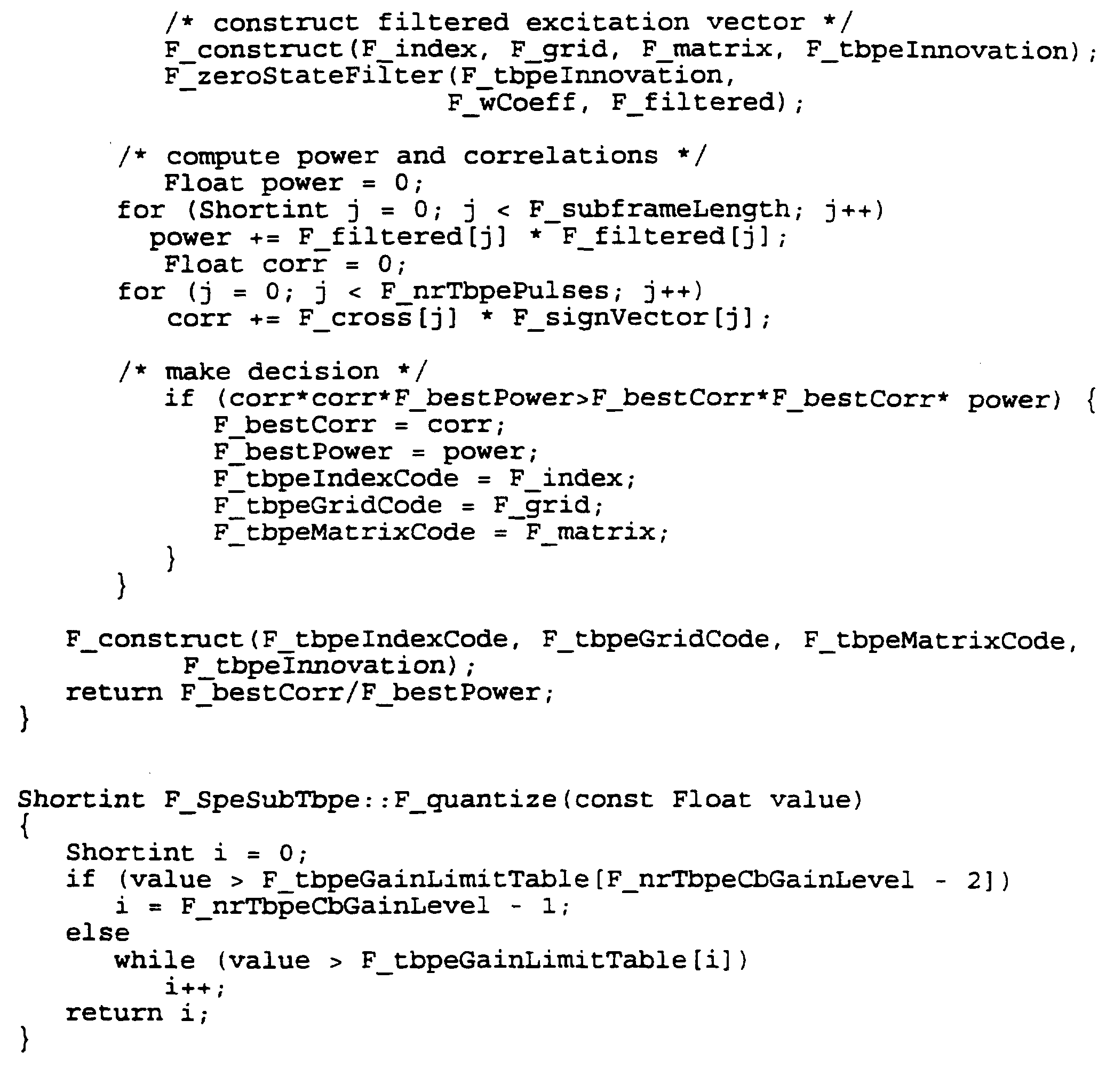
- An example of an algorithm used in the mixed excitation coder structure in accordance with the present invention is shown below.
- the algorithm contains all parts that are relevant in a speech encoder.
- the algorithm consists of six main sections.
- the MPE and TBPE sections, which constitute the mixed excitation are expanded to show the contents of the mixed excitation structure analysis.
- One frame based section e.g. for each 160 sample frame, is the LPC analysis section, which calculates and quantizes the short-term synthesis filter.
- the remaining five sections are sub-frame based, e.g. they are performed for each 40 sample sub-frame. The first of these is the sub-frame preprocessing, i.e. parameter extraction; the second is the long-term analysis or adaptive code book analysis; the third is the MPE analysis; the fourth is the TBPE analysis; and the fifth is the state update.
- MPE Multi-pulse excitation
- TPE Transformed binary pulse excitation
- BCELP Binary code excited linear prediction
- Binary pulse excitation A novel approach to low com plexity CELP coding.
- VSELP Vector sum excited linear prediction
- Excitation pulse positioning method in a linear predictive speech coder Excitation pulse positioning method in a linear predictive speech coder.
Landscapes
- Engineering & Computer Science (AREA)
- Computational Linguistics (AREA)
- Health & Medical Sciences (AREA)
- Audiology, Speech & Language Pathology (AREA)
- Human Computer Interaction (AREA)
- Physics & Mathematics (AREA)
- Acoustics & Sound (AREA)
- Multimedia (AREA)
- Signal Processing (AREA)
- Compression, Expansion, Code Conversion, And Decoders (AREA)
- Reduction Or Emphasis Of Bandwidth Of Signals (AREA)
Abstract
Description




Claims
Priority Applications (6)
| Application Number | Priority Date | Filing Date | Title |
|---|---|---|---|
| CA002214672A CA2214672C (en) | 1995-03-22 | 1996-03-06 | Analysis-by-synthesis linear predictive speech coder |
| DE69613360T DE69613360T2 (en) | 1995-03-22 | 1996-03-06 | LINEAR-PREDICTIVE ANALYSIS BY SYNTHESIS VOICE ENCODER |
| EP96908412A EP0815554B1 (en) | 1995-03-22 | 1996-03-06 | Analysis-by-synthesis linear predictive speech coder |
| JP52832596A JP3841224B2 (en) | 1995-03-22 | 1996-03-06 | Analysis / synthesis linear prediction speech coder |
| AU51654/96A AU699787B2 (en) | 1995-03-22 | 1996-03-06 | Analysis-by-synthesis linear predictive speech coder |
| US08/924,877 US5991717A (en) | 1995-03-22 | 1997-09-05 | Analysis-by-synthesis linear predictive speech coder with restricted-position multipulse and transformed binary pulse excitation |
Applications Claiming Priority (2)
| Application Number | Priority Date | Filing Date | Title |
|---|---|---|---|
| SE9501026A SE506379C3 (en) | 1995-03-22 | 1995-03-22 | Lpc speech encoder with combined excitation |
| SE9501026-0 | 1995-03-22 |
Related Child Applications (1)
| Application Number | Title | Priority Date | Filing Date |
|---|---|---|---|
| US08/924,877 Continuation US5991717A (en) | 1995-03-22 | 1997-09-05 | Analysis-by-synthesis linear predictive speech coder with restricted-position multipulse and transformed binary pulse excitation |
Publications (1)
| Publication Number | Publication Date |
|---|---|
| WO1996029696A1 true WO1996029696A1 (en) | 1996-09-26 |
Family
ID=20397640
Family Applications (1)
| Application Number | Title | Priority Date | Filing Date |
|---|---|---|---|
| PCT/SE1996/000296 Ceased WO1996029696A1 (en) | 1995-03-22 | 1996-03-06 | Analysis-by-synthesis linear predictive speech coder |
Country Status (11)
| Country | Link |
|---|---|
| US (1) | US5991717A (en) |
| EP (1) | EP0815554B1 (en) |
| JP (1) | JP3841224B2 (en) |
| KR (1) | KR100368897B1 (en) |
| AU (1) | AU699787B2 (en) |
| CA (1) | CA2214672C (en) |
| DE (1) | DE69613360T2 (en) |
| ES (1) | ES2162038T3 (en) |
| RU (1) | RU2163399C2 (en) |
| SE (1) | SE506379C3 (en) |
| WO (1) | WO1996029696A1 (en) |
Cited By (13)
| Publication number | Priority date | Publication date | Assignee | Title |
|---|---|---|---|---|
| FR2776447A1 (en) * | 1998-03-23 | 1999-09-24 | Comsis | Digital word compressing coding method |
| WO2001022676A1 (en) * | 1999-09-21 | 2001-03-29 | Comsis | Block joint source-channel coding |
| WO2003001172A1 (en) * | 2001-06-21 | 2003-01-03 | Nokia Corporation | Method and device for coding speech in analysis-by-synthesis speech coders |
| RU2319222C1 (en) * | 2006-08-30 | 2008-03-10 | Валерий Юрьевич Тарасов | Method for encoding and decoding speech signal using linear prediction method |
| US9037457B2 (en) | 2011-02-14 | 2015-05-19 | Fraunhofer-Gesellschaft Zur Foerderung Der Angewandten Forschung E.V. | Audio codec supporting time-domain and frequency-domain coding modes |
| US9047859B2 (en) | 2011-02-14 | 2015-06-02 | Fraunhofer-Gesellschaft Zur Foerderung Der Angewandten Forschung E.V. | Apparatus and method for encoding and decoding an audio signal using an aligned look-ahead portion |
| US9153236B2 (en) | 2011-02-14 | 2015-10-06 | Fraunhofer-Gesellschaft Zur Foerderung Der Angewandten Forschung E.V. | Audio codec using noise synthesis during inactive phases |
| US9384739B2 (en) | 2011-02-14 | 2016-07-05 | Fraunhofer-Gesellschaft Zur Foerderung Der Angewandten Forschung E.V. | Apparatus and method for error concealment in low-delay unified speech and audio coding |
| US9536530B2 (en) | 2011-02-14 | 2017-01-03 | Fraunhofer-Gesellschaft Zur Foerderung Der Angewandten Forschung E.V. | Information signal representation using lapped transform |
| US9583110B2 (en) | 2011-02-14 | 2017-02-28 | Fraunhofer-Gesellschaft Zur Foerderung Der Angewandten Forschung E.V. | Apparatus and method for processing a decoded audio signal in a spectral domain |
| US9595263B2 (en) | 2011-02-14 | 2017-03-14 | Fraunhofer-Gesellschaft Zur Foerderung Der Angewandten Forschung E.V. | Encoding and decoding of pulse positions of tracks of an audio signal |
| US9595262B2 (en) | 2011-02-14 | 2017-03-14 | Fraunhofer-Gesellschaft Zur Foerderung Der Angewandten Forschung E.V. | Linear prediction based coding scheme using spectral domain noise shaping |
| US9620129B2 (en) | 2011-02-14 | 2017-04-11 | Fraunhofer-Gesellschaft Zur Foerderung Der Angewandten Forschung E.V. | Apparatus and method for coding a portion of an audio signal using a transient detection and a quality result |
Families Citing this family (27)
| Publication number | Priority date | Publication date | Assignee | Title |
|---|---|---|---|---|
| FI955266A7 (en) * | 1995-11-02 | 1997-05-03 | Nokia Corp | Method and apparatus for transmitting messages in a telecommunications system |
| JP3199020B2 (en) | 1998-02-27 | 2001-08-13 | 日本電気株式会社 | Audio music signal encoding device and decoding device |
| FI113571B (en) * | 1998-03-09 | 2004-05-14 | Nokia Corp | speech Coding |
| ATE520122T1 (en) * | 1998-06-09 | 2011-08-15 | Panasonic Corp | VOICE CODING AND VOICE DECODING |
| SE521225C2 (en) * | 1998-09-16 | 2003-10-14 | Ericsson Telefon Ab L M | Method and apparatus for CELP encoding / decoding |
| US6292917B1 (en) * | 1998-09-30 | 2001-09-18 | Agere Systems Guardian Corp. | Unequal error protection for digital broadcasting using channel classification |
| JP4008607B2 (en) * | 1999-01-22 | 2007-11-14 | 株式会社東芝 | Speech encoding / decoding method |
| US7272553B1 (en) * | 1999-09-08 | 2007-09-18 | 8X8, Inc. | Varying pulse amplitude multi-pulse analysis speech processor and method |
| US6529867B2 (en) * | 2000-09-15 | 2003-03-04 | Conexant Systems, Inc. | Injecting high frequency noise into pulse excitation for low bit rate CELP |
| SE519976C2 (en) * | 2000-09-15 | 2003-05-06 | Ericsson Telefon Ab L M | Coding and decoding of signals from multiple channels |
| SE0004818D0 (en) * | 2000-12-22 | 2000-12-22 | Coding Technologies Sweden Ab | Enhancing source coding systems by adaptive transposition |
| CA2415105A1 (en) * | 2002-12-24 | 2004-06-24 | Voiceage Corporation | A method and device for robust predictive vector quantization of linear prediction parameters in variable bit rate speech coding |
| RU2248619C2 (en) * | 2003-02-12 | 2005-03-20 | Рыболовлев Александр Аркадьевич | Method and device for converting speech signal by method of linear prediction with adaptive distribution of information resources |
| KR20050028193A (en) * | 2003-09-17 | 2005-03-22 | 삼성전자주식회사 | Method for adaptively inserting additional information into audio signal and apparatus therefor, method for reproducing additional information inserted in audio data and apparatus therefor, and recording medium for recording programs for realizing the same |
| DE102004007185B3 (en) * | 2004-02-13 | 2005-06-30 | Fraunhofer-Gesellschaft zur Förderung der angewandten Forschung e.V. | Predictive coding method for information signals using adaptive prediction algorithm with switching between higher adaption rate and lower prediction accuracy and lower adaption rate and higher prediction accuracy |
| JP2008503786A (en) * | 2004-06-22 | 2008-02-07 | コーニンクレッカ フィリップス エレクトロニクス エヌ ヴィ | Audio signal encoding and decoding |
| DE102005000830A1 (en) * | 2005-01-05 | 2006-07-13 | Siemens Ag | Bandwidth extension method |
| US7610195B2 (en) * | 2006-06-01 | 2009-10-27 | Nokia Corporation | Decoding of predictively coded data using buffer adaptation |
| WO2010017840A1 (en) * | 2008-08-13 | 2010-02-18 | Nokia Siemens Networks Oy | Method of generating a codebook |
| RU2400832C2 (en) * | 2008-11-24 | 2010-09-27 | Государственное образовательное учреждение высшего профессионального образования Академия Федеральной службы охраны Российской Федерации (Академия ФCО России) | Method for generation of excitation signal in low-speed vocoders with linear prediction |
| US8924222B2 (en) | 2010-07-30 | 2014-12-30 | Qualcomm Incorporated | Systems, methods, apparatus, and computer-readable media for coding of harmonic signals |
| US9208792B2 (en) | 2010-08-17 | 2015-12-08 | Qualcomm Incorporated | Systems, methods, apparatus, and computer-readable media for noise injection |
| RU2495504C1 (en) * | 2012-06-25 | 2013-10-10 | Государственное казенное образовательное учреждение высшего профессионального образования Академия Федеральной службы охраны Российской Федерации (Академия ФСО России) | Method of reducing transmission rate of linear prediction low bit rate voders |
| EP3671738B1 (en) * | 2013-04-05 | 2024-06-05 | Dolby International AB | Audio encoder and decoder |
| EP3217398B1 (en) * | 2013-04-05 | 2019-08-14 | Dolby International AB | Advanced quantizer |
| RU2631968C2 (en) * | 2015-07-08 | 2017-09-29 | Федеральное государственное казенное военное образовательное учреждение высшего образования "Академия Федеральной службы охраны Российской Федерации" (Академия ФСО России) | Method of low-speed coding and decoding speech signal |
| TWI723545B (en) * | 2019-09-17 | 2021-04-01 | 宏碁股份有限公司 | Speech processing method and device thereof |
Citations (4)
| Publication number | Priority date | Publication date | Assignee | Title |
|---|---|---|---|---|
| US4932061A (en) * | 1985-03-22 | 1990-06-05 | U.S. Philips Corporation | Multi-pulse excitation linear-predictive speech coder |
| US4991215A (en) * | 1986-04-15 | 1991-02-05 | Nec Corporation | Multi-pulse coding apparatus with a reduced bit rate |
| US4991214A (en) * | 1987-08-28 | 1991-02-05 | British Telecommunications Public Limited Company | Speech coding using sparse vector codebook and cyclic shift techniques |
| US5193140A (en) * | 1989-05-11 | 1993-03-09 | Telefonaktiebolaget L M Ericsson | Excitation pulse positioning method in a linear predictive speech coder |
Family Cites Families (5)
| Publication number | Priority date | Publication date | Assignee | Title |
|---|---|---|---|---|
| GB8621932D0 (en) * | 1986-09-11 | 1986-10-15 | British Telecomm | Speech coding |
| US4980916A (en) * | 1989-10-26 | 1990-12-25 | General Electric Company | Method for improving speech quality in code excited linear predictive speech coding |
| US5195168A (en) * | 1991-03-15 | 1993-03-16 | Codex Corporation | Speech coder and method having spectral interpolation and fast codebook search |
| JPH0612098A (en) * | 1992-03-16 | 1994-01-21 | Sanyo Electric Co Ltd | Voice encoding device |
| JP3328080B2 (en) * | 1994-11-22 | 2002-09-24 | 沖電気工業株式会社 | Code-excited linear predictive decoder |
-
1995
- 1995-03-22 SE SE9501026A patent/SE506379C3/en not_active IP Right Cessation
-
1996
- 1996-03-06 KR KR1019970706601A patent/KR100368897B1/en not_active Expired - Lifetime
- 1996-03-06 WO PCT/SE1996/000296 patent/WO1996029696A1/en not_active Ceased
- 1996-03-06 DE DE69613360T patent/DE69613360T2/en not_active Expired - Lifetime
- 1996-03-06 CA CA002214672A patent/CA2214672C/en not_active Expired - Lifetime
- 1996-03-06 RU RU97117357/09A patent/RU2163399C2/en active
- 1996-03-06 EP EP96908412A patent/EP0815554B1/en not_active Expired - Lifetime
- 1996-03-06 JP JP52832596A patent/JP3841224B2/en not_active Expired - Lifetime
- 1996-03-06 AU AU51654/96A patent/AU699787B2/en not_active Expired
- 1996-03-06 ES ES96908412T patent/ES2162038T3/en not_active Expired - Lifetime
-
1997
- 1997-09-05 US US08/924,877 patent/US5991717A/en not_active Expired - Lifetime
Patent Citations (4)
| Publication number | Priority date | Publication date | Assignee | Title |
|---|---|---|---|---|
| US4932061A (en) * | 1985-03-22 | 1990-06-05 | U.S. Philips Corporation | Multi-pulse excitation linear-predictive speech coder |
| US4991215A (en) * | 1986-04-15 | 1991-02-05 | Nec Corporation | Multi-pulse coding apparatus with a reduced bit rate |
| US4991214A (en) * | 1987-08-28 | 1991-02-05 | British Telecommunications Public Limited Company | Speech coding using sparse vector codebook and cyclic shift techniques |
| US5193140A (en) * | 1989-05-11 | 1993-03-09 | Telefonaktiebolaget L M Ericsson | Excitation pulse positioning method in a linear predictive speech coder |
Non-Patent Citations (4)
| Title |
|---|
| ADVANCES IN SPEECH CODING, KLUWER ACADEMIC PUBLISHERS, 1991, R.A. SALAMI, "Binary Pulse Excitation: A Novel Approach to Low Complexity CELP Coding", pp. 145-156. * |
| IEEE COLLOQUIUM ON TECHNIQUES FOR SPEECH PROCESSING AND ...., June 1994, F.J. ANCIN et al., "A Hybrid Wavelet-Binary Pulse Excitation Approach for High Quality CELP Speech Coding", pp. 1/1-1/6. * |
| IEEE INT. CONFERENCE ON ACOUSTICS, SPEECH AND SIGNAL PROCESSING, Volume 1, May 1991, A. HERMANSSON et al., "A Speech Codec for Cellular Radio at a Gross Bit Rate of 11.4 Kb/s", pp. 625-628. * |
| INT. SYMPOSIUM ON SPEECH, IMAGE PROCESSING AND NEURAL NETWORKS, Volume 2, April 1994, G. YANG et al., "A Robust and fast DP-CELP (Double-Pulse) Vocoder at the Bit Rate of 4 Kbit/s", pp. 563-566. * |
Cited By (14)
| Publication number | Priority date | Publication date | Assignee | Title |
|---|---|---|---|---|
| FR2776447A1 (en) * | 1998-03-23 | 1999-09-24 | Comsis | Digital word compressing coding method |
| WO2001022676A1 (en) * | 1999-09-21 | 2001-03-29 | Comsis | Block joint source-channel coding |
| WO2003001172A1 (en) * | 2001-06-21 | 2003-01-03 | Nokia Corporation | Method and device for coding speech in analysis-by-synthesis speech coders |
| CN100489966C (en) * | 2001-06-21 | 2009-05-20 | 诺基亚有限公司 | Method and device for coding speech in analysis-by-synthesis speech coders |
| RU2319222C1 (en) * | 2006-08-30 | 2008-03-10 | Валерий Юрьевич Тарасов | Method for encoding and decoding speech signal using linear prediction method |
| US9047859B2 (en) | 2011-02-14 | 2015-06-02 | Fraunhofer-Gesellschaft Zur Foerderung Der Angewandten Forschung E.V. | Apparatus and method for encoding and decoding an audio signal using an aligned look-ahead portion |
| US9037457B2 (en) | 2011-02-14 | 2015-05-19 | Fraunhofer-Gesellschaft Zur Foerderung Der Angewandten Forschung E.V. | Audio codec supporting time-domain and frequency-domain coding modes |
| US9153236B2 (en) | 2011-02-14 | 2015-10-06 | Fraunhofer-Gesellschaft Zur Foerderung Der Angewandten Forschung E.V. | Audio codec using noise synthesis during inactive phases |
| US9384739B2 (en) | 2011-02-14 | 2016-07-05 | Fraunhofer-Gesellschaft Zur Foerderung Der Angewandten Forschung E.V. | Apparatus and method for error concealment in low-delay unified speech and audio coding |
| US9536530B2 (en) | 2011-02-14 | 2017-01-03 | Fraunhofer-Gesellschaft Zur Foerderung Der Angewandten Forschung E.V. | Information signal representation using lapped transform |
| US9583110B2 (en) | 2011-02-14 | 2017-02-28 | Fraunhofer-Gesellschaft Zur Foerderung Der Angewandten Forschung E.V. | Apparatus and method for processing a decoded audio signal in a spectral domain |
| US9595263B2 (en) | 2011-02-14 | 2017-03-14 | Fraunhofer-Gesellschaft Zur Foerderung Der Angewandten Forschung E.V. | Encoding and decoding of pulse positions of tracks of an audio signal |
| US9595262B2 (en) | 2011-02-14 | 2017-03-14 | Fraunhofer-Gesellschaft Zur Foerderung Der Angewandten Forschung E.V. | Linear prediction based coding scheme using spectral domain noise shaping |
| US9620129B2 (en) | 2011-02-14 | 2017-04-11 | Fraunhofer-Gesellschaft Zur Foerderung Der Angewandten Forschung E.V. | Apparatus and method for coding a portion of an audio signal using a transient detection and a quality result |
Also Published As
| Publication number | Publication date |
|---|---|
| KR19980703198A (en) | 1998-10-15 |
| CA2214672C (en) | 2005-07-05 |
| CA2214672A1 (en) | 1996-09-26 |
| SE9501026D0 (en) | 1995-03-22 |
| RU2163399C2 (en) | 2001-02-20 |
| SE506379C3 (en) | 1998-01-19 |
| DE69613360T2 (en) | 2001-10-11 |
| JPH11502318A (en) | 1999-02-23 |
| US5991717A (en) | 1999-11-23 |
| KR100368897B1 (en) | 2003-04-11 |
| EP0815554B1 (en) | 2001-06-13 |
| SE506379C2 (en) | 1997-12-08 |
| EP0815554A1 (en) | 1998-01-07 |
| ES2162038T3 (en) | 2001-12-16 |
| AU5165496A (en) | 1996-10-08 |
| DE69613360D1 (en) | 2001-07-19 |
| AU699787B2 (en) | 1998-12-17 |
| JP3841224B2 (en) | 2006-11-01 |
| SE9501026L (en) | 1996-09-23 |
Similar Documents
| Publication | Publication Date | Title |
|---|---|---|
| US5991717A (en) | Analysis-by-synthesis linear predictive speech coder with restricted-position multipulse and transformed binary pulse excitation | |
| US6141638A (en) | Method and apparatus for coding an information signal | |
| KR100264863B1 (en) | Method for speech coding based on a celp model | |
| US5138661A (en) | Linear predictive codeword excited speech synthesizer | |
| KR100900113B1 (en) | Dispersed pulse vector generator and method for generating a dispersed pulse vector | |
| JP4064236B2 (en) | Indexing method of pulse position and code in algebraic codebook for wideband signal coding | |
| AU719568B2 (en) | Method for searching an excitation codebook in a code excited linear prediction (CELP) coder | |
| EP0824750B1 (en) | A gain quantization method in analysis-by-synthesis linear predictive speech coding | |
| Salami et al. | 8 kbit/s ACELP coding of speech with 10 ms speech-frame: A candidate for CCITT standardization | |
| US5513297A (en) | Selective application of speech coding techniques to input signal segments | |
| Kataoka et al. | An 8-bit/s speech coder based on conjugate structure CELP | |
| KR100465316B1 (en) | Speech encoder and speech encoding method thereof | |
| US7337110B2 (en) | Structured VSELP codebook for low complexity search | |
| CA2336360C (en) | Speech coder | |
| Salami | Binary pulse excitation: A novel approach to low complexity CELP coding | |
| Ramirez et al. | A multistage search of algebraic CELP codebooks | |
| Akamine et al. | CELP coding with an adaptive density pulse excitation model | |
| JP3103108B2 (en) | Audio coding device | |
| CA2598683C (en) | A speech encoder and method of speech encoding | |
| JP3284874B2 (en) | Audio coding device | |
| KR20010073146A (en) | Method and apparatus for coding an information signal | |
| Choi et al. | On Reducing the Complexity of the VSELP Coder |
Legal Events
| Date | Code | Title | Description |
|---|---|---|---|
| WWE | Wipo information: entry into national phase |
Ref document number: 96192752.6 Country of ref document: CN |
|
| AK | Designated states |
Kind code of ref document: A1 Designated state(s): AL AM AT AU AZ BB BG BR BY CA CH CN CZ DE DK EE ES FI GB GE HU IS JP KE KG KP KR KZ LK LR LS LT LU LV MD MG MK MN MW MX NO NZ PL PT RO RU SD SE SG SI SK TJ TM TR TT UA UG US UZ VN AM AZ BY KG KZ MD RU TJ TM |
|
| AL | Designated countries for regional patents |
Kind code of ref document: A1 Designated state(s): KE LS MW SD SZ UG AT BE CH DE DK ES FI FR GB GR IE IT LU MC NL PT SE BF BJ CF CG CI CM GA GN |
|
| DFPE | Request for preliminary examination filed prior to expiration of 19th month from priority date (pct application filed before 20040101) | ||
| 121 | Ep: the epo has been informed by wipo that ep was designated in this application | ||
| WWE | Wipo information: entry into national phase |
Ref document number: 1996908412 Country of ref document: EP |
|
| ENP | Entry into the national phase |
Ref document number: 2214672 Country of ref document: CA Ref document number: 2214672 Country of ref document: CA Kind code of ref document: A |
|
| ENP | Entry into the national phase |
Ref document number: 1996 528325 Country of ref document: JP Kind code of ref document: A |
|
| WWE | Wipo information: entry into national phase |
Ref document number: 1019970706601 Country of ref document: KR |
|
| WWP | Wipo information: published in national office |
Ref document number: 1996908412 Country of ref document: EP |
|
| REG | Reference to national code |
Ref country code: DE Ref legal event code: 8642 |
|
| WWP | Wipo information: published in national office |
Ref document number: 1019970706601 Country of ref document: KR |
|
| WWG | Wipo information: grant in national office |
Ref document number: 1996908412 Country of ref document: EP |
|
| WWG | Wipo information: grant in national office |
Ref document number: 1019970706601 Country of ref document: KR |