CORROSION INHIBITOR FOR WELLBORE APPLICATIONS
Background of the Invention
This invention relates to a corrosion inhibitor and the use thereof in wellbore
applications.
Aerated liquids and foams are frequently employed as wellbore fluids during
drilling, completion, workover and production operations. Aerated as used herein refers to the
existence of distinct gas and liquid phases. Aerated liquids are distinguishable from foams by
the absence or the presence in de minimis amounts of surface active agents which promote
gas-liquid interphase dispersibility.
Aerated liquids and foams are particularly useful when reduced hydrostatic
pressures in wellbores are desired. The reduced hydrostatic pressure or head is made possible
by the lower bulk densities of aerated liquids and foams when compared to their liquid
counterparts. Examples wherein reduced hydrostatic heads are favored include (1) situations
where the wellbore fluids are exposed to under-pressured geological strata and minimum
invasion of the strata by the wellbore fluid is desired and (2) during the perforation of a
geological strata at underbalanced conditions (i.e., wellbore pressure less than fluid pressure
in exposed strata)wherein the reduced head helps to minimize plugging of the perforation
caused by movement of fines into the perforation from the wellbore.
Aerated liquids are nominally comprised of a gas and a liquid and may
additionally contain additives such as corrosion inhibitors and suspended solids such as mud
and sand. Aerated fluids useful in drilling, completion, workover and production operations
are typically prepared by the downhole combination of a gas and a liquid. In drilling, one
means of combining these components downhole is by the use of dual drill strings and dual
swivels. Another means frequently used in downhole applications is to employ parasitic
tubing for transporting the gas downhole to an injection point where it is combined with liquid
and returned to the surface. Injection of gas at any downhole location serves to reduce the
bottomhole hydrostatic head from that of a 100% liquid head. Downhole gas injection is also
practiced when gas lift is used to facilitate fluids production in a well. Foams are highly
dispersed gas in liquid two-phase systems. A foam is physically composed of gas bubbles
surrounded by a surfactant-bearing aqueous film and is nominally comprised of a gas, at least
one surfactant which functions as a foaming agent, and water. The quality of the foam or
foam quality is defined to be the volume percent of gas in the two-phase mixture. The water
used in foams may be chemically pure, fresh, or contain varying degrees of salinity and/or
hardness. The foam may additionally be comprised of other additives which alter the
properties of the foam. Such additives include selected polymers and/or bentonite which
increase film strength thereby forming stiff or gel foams and corrosion inhibitors which
function to decrease foam corrosivity in metal-bearing systems.
The rheological properties of foam are complex and provide a separate and
distinct basis for distinguishing foam from aerated and non-aerated liquids. The rheological
properties are dependent upon many parameters such as bubble size and distribution, fluid
viscosity, foam quality, and the concentration and type of foaming agent used. The use of
foam in place of conventional fluids generally reduces the degree of fluid invasion from the
wellbore into the surrounding strata. Furthermore, the foam which does invade the strata
generally contains a high volume percentage of gas which upon pressurization possesses
significant energy. Upon depressurization, the stored energy which is released causes a
significant portion of this fluid to be returned to the wellbore. Compared to conventional
fluids, foam also possesses at low linear flow velocities excellent carrying capacities,
particularly for water and solids. These properties are particularly useful when conducting
drilling, completion and workover operations on vertical and horizontal wells and even more
so when low pressure, semi-depleted or water sensitive formations are encountered. The
unique properties of foam also enable the use of coiled tubing units during workover
operations. The use of such units results in significant savings of time and money because
downhole operations can be performed without removal of the wellbore tubing.
Historically, a major problem associated with the use of aerated liquids and foams
has been metal corrosion attributed to the presence of oxidizing agents such as oxygen,
hydrogen sulfide and carbon dioxide in the gas phase. Oxygen generally originates from air.
Carbon dioxide and hydrogen sulfide are generally produced from the geological strata of
interest. Corrosion problems generally become more severe as wellbore temperatures
increase. Because of cost and availability, air is the preferred gaseous species when downhole
corrosion is not a problem. However, because of the lack of suitable corrosion inhibitors
when downhole conditions become severe ((i.e., high temperatures and the presence of
significant quantities of oxidizing agents), inert gases which are expensive, most notably
nitrogen, are frequently used.
Summary of the Invention
It is an object of this invention to develop a corrosion inhibitor suitable for use in
gas-liquid systems at oxidative conditions.
It is a further object of this invention to develop a corrosion-inhibited gas-liquid
mixture suitable for use under oxidative conditions.
It is a still further object of this invention to develop a corrosion-inhibited foam
suitable for use under oxidative conditions.
It is yet a still further object of this invention to develop a corrosion-inhibited
oxygen-bearing gas/liquid mixture suitable for use in wellbore applications including drilling,
workover, completion and production.
It is still yet a further object of this invention to develop a corrosion-inhibited
air/liquid mixture suitable for use at temperatures of at least about 200 °F.
Still a further object of this invention to develop a corrosion inhibited oxygen-
bearing gas/liquid mixture wherein the chemicals imparting the corrosion-inhibition
properties are relatively inexpensive commodity chemicals.
A yet still further object is to develop a process employing foam suitable for use
under highly oxidative conditions in the drilling, completion, workover and production of
wells.
In accordance with this invention, a formulation for a corrosion inhibitor
comprised of a phenolic compound and a hydroxide-bearing compound capable of imparting
basicity to water has been discovered.
In a second embodiment, a corrosion-inhibited gas-liquid mixture nominally
comprised of a gas, water, a phenolic compound and a hydroxide-bearing compound capable
of imparting basicity to water has been discovered.
In a third embodiment, a novel corrosion-inhibited gas foam nominally
comprised of gas, water, foaming agent, and a corrosion inhibitor comprised of a phenolic
compound and a hydroxide-bearing compound capable of imparting basicity to water has been
discovered.
In a fourth embodiment, a process utilizing the inventive gas-liquid mixture under
oxidative conditions such as those existing in wellbore applications has been discovered.
And in a fifth embodiment, a process utilizing the inventive foam under oxidative
conditions such as those existing in wellbore applications has been discovered.
Description of the Invention
In its multiple embodiments, this invention concerns a unique formulation for a
corrosion inhibitor, a formulation for corrosion-inhibited aerated liquids, a formulation for
corrosion-inhibited foams, and the use thereof of the aerated liquids or foams in wellbore
applications which include drilling, workover, completion and production operations.
Corrosion Inhibitor
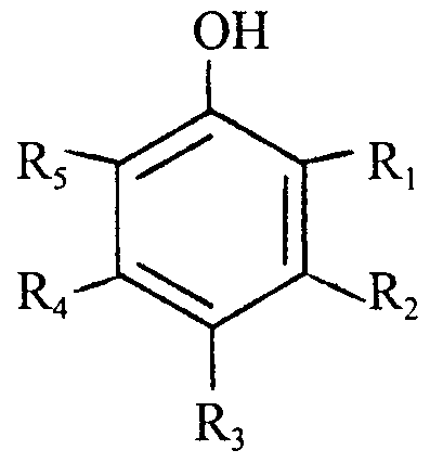
The inventive corrosion inhibitor is nominally comprised of at least one phenolic
compound including the salts thereof and at least one hydroxide-bearing compound capable of
imparting a pH of at least 9 to an aqueous phase. The hydroxy-bearing hydrocarbon
compound is preferably a phenolic compound of the formula
OH
wherein R
b R
2, R
3, R
4 and R
5 are independently selected from the group consisting of
hydroxyl groups, alkoxy groups containing from 1 to 6 carbon atoms; alkyl groups containing
from 1 to 6 carbon atoms, a phenyl group, NO2, COOH, COH, sulfonic acids, ketones
containing from 1 to 6 carbon atoms, F, Cl, Br, I, hydrogen, or the salts of any of the
preceding acids or alcohols, wherein at least two of the above R groups are hydrogen; or
phenolic mixtures thereof, and the resulting compound is water dispersible or soluable.
Another group of compounds included within the term phenolic compound are
the flavotannins. Flavotannins are polyphenolic materials which are extracted from the bark
and wood of trees. Quebracho is an example of a suitable flavotannin.
Representative examples of suitable phenolic compounds are those selected from
the group consisting of monohydroxy phenols, polyhydroxy phenols, monohydroxy
naphthols, polyhydroxy naphthols, o-cresol, m-cresol, p-cresol, o-fluorophenol, m-
fluorophenol, p-fluorophenol, o-chlorophenol, m-chlorophenol, p-chlorophenol, o-
bromophenol, m-bromophenol, p-bromophenol, o-iodophenol, m-iodophenol, p-iodophenol,
o-nitrophenol, m-nitrophenol, p-nitrophenol, flavotannins, phenol, resorcinol, catechol,
hydroquinone, phloroglucinol, pyrogallol, 1,3-dihydroxynaphthalene, o-methoxyphenol, p-
methoxyphenol, m-methyoxyphenol, o-hydroxybenzoic acid, p-hydroxybenzoic acid, m-
hydroxybenzoic acid, o-phenolsulfonic acid, p-phenolsulfonic acid, m-phenolsulfonic acid,
dichlorophenols, 4,4-biphenol, salicylaldehyde, guaiacol and the salts of the preceding acids
and alcohols or mixtures thereof selected from the preceding group.
The phenolic compound is more preferably phenol, o-cresol, o-fluorophenol, o-
chlorophenol, o-bromophenol, o-iodophenol, o-nitrophenol, catechol, resorcinol, guaiacol,
hydroquinone, salicylaldehyde, phloroglucinol, pyrogallol, 4,4-biphenol, 1,3-dihydroxy
naphthalene or o-allylphenol or any of the salts of the preceding or mixtures thereof of the
preceding. Still more preferred are those selected from the group consisting of phenol, o-
cresol, salicylaldehyde, o-nitrophenol and the ammonium, sodium and potassium salts thereof
or mixtures of the preceding. The most preferred phenolate salts are those of sodium and
potassium. Based on performance, cost, and commercial availability, the most preferred
phenolic compounds are phenol and the sodium and potassium salts thereof which are sodium
phenolate and potassium phenolate.
The hydroxide-bearing compound must be a compound capable of imparting a
pH of 9 to an aqueous phase. Preferred hydroxide-bearing compounds are the alkali metal
hydroxides, ammonium hydroxide or mixtures thereof. More preferred are those selected
from the group consisting of ammonium hydroxide, sodium hydroxide and potassium
hydroxide. Of these, sodium hydroxide and potassium hydroxide are still more preferred.
Most preferred is potassium hydroxide.
The hydroxide-bearing compound must be present in an amount effective to
insure appreciable dissociation of the hydrogen atoms associated with the hydroxyl group or
groups on the phenolic compound. On a molar basis, a mole ratio of hydroxide-bearing
compound to phenolic compound of 5 to 1000 is preferred. A mole ratio of about 10 to about
500 more preferred. A ratio of about 20 to about 350 is most preferred. When using the
preferred hydroxide-bearing compounds consisting of ammonium hydroxide, potassium
hydroxide or sodium hydroxide or mixtures thereof and the most preferred phenolic
compound, phenol, a hydroxide compound to phenol weight ratio of about 10 to about 70 is
preferred. When using the more preferred sodium hydroxide and potassium hydroxide
species, a weight ratio of about 10 to about 40 is preferred.
The corrosion inhibitor may additionally be comprised of water in an amount
effective to function as a dispersing or carrying agent for the phenolic compound and the
hydroxide-bearing compound thereby simplifying the mixing of these components with other
components when preparing aerated liquids or foams. The water may be chemically pure,
fresh or contain appreciable salinity and/or hardness and may contain dissolved gases which
favor oxidation.
The inventive corrosion inhibitor is distinguished from many other inhibitors,
particularly scavengers, by its ability to effectively function when the molar ratio of a key
active component, the phenolic compound, to the oxidizing agent or agents in the system is
significantly less than 1. The corrosion inhibitor is effective at both ambient and elevated
temperatures. The inventive inhibitor is also distinguishable from many commercially
available inhibitors by its effectiveness at temperatures of at least about 200 °F and is further
distinguished by its superior corrosion inhibition properties at temperatures of at least about
350°F. The corrosion inhibitor is particularly effective when the oxidizing agent is oxygen or
the oxidation-related compounds thereof.
Corrosion-Inhibited Aerated Liquid
A corrosion-inhibited aerated liquid possessing various utilities as a wellbore
fluid has been discovered. The aerated liquid is nominally comprised of a gas which contains
an oxidizing agent, water, and the inventive corrosion inhibitor described in the previous
section. As previously noted, the corrosion inhibitor is particularly effective when the
oxidizing agents are hydrogen sulfide, carbon dioxide, and oxygen or oxidation-related
compounds to these agents. Treatment of aerated liquids containing oxygen as the oxidizing
agent is preferred. The water may be chemically pure, fresh, or contain appreciable salinitv
and/or hardness and may contain dissolved gases, some of which may favor oxidation. The
aerated liquid may additionally be comprised of solids such as sand and dirt or a separate
organic phase.
Aerated liquids are particularly useful when a reduction in the bulk density of the
base liquid is desired. Such a need frequently occurs in wellbore applications when a
reduction in hydrostatic head is desired.
An aerated liquid is prepared by combining a gas containing at least one
oxidizing agent, a water-based liquid, and the corrosion inhibitor using ordinary skill in the
art. Preferably, the water-based liquid and corrosion inhibitor are first combined to form a
corrosion inhibited liquid. The gas is then added via contacting the liquid and gas phases. In
the drilling, completion, workover, or production of a well, the latter contacting step is usually
conducted downhole in a borehole using ordinary skill in the art.
The corrosion inhibitor may also be used in well production wherein gas lift
technology is used. In such an application, the corrosion inhibitor may be combined
downhole with the gas used for gas lift and the produced fluids which contain water. In such
an application, the reduced hydrostatic head allows the reservoir fluids, which may also
include a separate gas phase, to flow to the surface using the existing reservoir pressure as the
driving force thereby avoiding the use of more complicated and expensive means of
production such as pumpjacks, submersible pumps, etc. In such an operation, gaseous
oxidizing agents such as hydrogen sulfide, carbon dioxide, or oxygen and oxidation-related
compounds of these agents may be present in either the gas used for the gas lift or in the fluids
produced from the reservoir.
The required concentration of corrosion inhibitor in the aerated fluid is that
amount effective to insure corrosion inhibition over the time frame of interest at the
conditions of interest. These concentrations may be readily ascertained by one skilled in the
art via routine test procedures. Generally, the preferred weight percent of hydroxide-bearing
compound and phenolic compound based on the combined weight of water and corrosion
inhibitor are about 0.1 to about 40 wt% and about 0.005 to about 4.0 wt%, respectively. More
preferred are respective weight percent ranges of about 1 to about 20 wt% and about 0.01 to
about 0.50 wt%, respectively. Still more preferred are respective weight percent ranges of
about 1 to about 10 and about 0.05 to about 0.30. The most preferred weight percent ranges
are about 5 to about 10 and about 0.10 to about 0.30, respectively.
One factor distinguishing the inventive corrosion inhibitor from other inhibitors,
particularly scavengers, when incorporated into aerated liquid, is the ability of the inhibitor to
effectively function when the molar ratio of a key active component, the phenolic compound,
to the oxidizing agent or agents in the system is significantly less that 1. The corrosion-
inhibited aerated liquid may be used in metal-bearing systems at both ambient and elevated
temperatures. An additional factor distinguishing the inventive inhibitor from the many
commercially available inhibitors is its effectiveness at temperatures of about or greater than
200 °F and even more so, its effectiveness at temperatures of about or greater than 350 °F. The
corrosion inhibitor when incorporated into an aerated liquid is particularly effective when the
oxidizing agent is oxygen or the oxidation-related compounds thereof.
Corrosion-Inhibited Foam
The inventive corrosion-inhibited foam is nominally comprised of a dispersed gas
phase wherein the gas contains an oxidizing agent and a continuous liquid phase nominally
comprised of a foaming agent, water in a major portion, and the inventive corrosion inhibitor.
The water may be chemically pure, fresh, or contain appreciable salinity and/or hardness, and
may contain dissolved gases, some of which may favor oxidation. At the discretion of one
skilled in the art, the liquid phase may contain other additives which function to produce a
better performing foam at the conditions of use. Foam stabilizers are one such example. The
foam may additionally contain solids such as sand and dirt and/or a separate organic phase.
The volume percentage of the combined gaseous and liquid phase which is gas is defined
to be the foam quality. The quality of the foam is preferably about 60 to about 99.75% and
more preferably about 75 to about 99.5 volume percent at wellbore conditions. The properties
of the foam may be altered by the use of various additives known to those skilled in the art.
As an example, a stiffer foam may be prepared by adding guar gum or other organic polymers
and solids such as bentonite to the base components.
The gaseous phase may initially contain an oxidizing agent or the phase may be
inert and absorb oxidizing agents such as oxygen, hydrogen sulfide or carbon dioxide or
oxidation-related compounds during the course of process operation. Because of the
effectiveness of the inventive corrosion inhibitor, when oxygen is the oxidizing species,
inhibited foams containing oxygen are particularly favored. Because of cost and availability,
a gaseous phase comprised in major portion of air is preferred.
As previously discussed for the aerated liquid, corrosion inhibitor in an amount
effective to insure corrosion inhibition over the time frame of interest at the conditions of
interest is required. These concentrations may be readily ascertained by one skilled in the art
via routine test procedures. Specific ranges of preference based on the combined weight
percentage of water, corrosion inhibitor and foaming agent are identical to those reported for
the aerated liquid wherein said weight percentage was based on water and corrosion inhibitor.
One factor distinguishing the inventive corrosion inhibitor from other inhibitors,
particularly scavengers, when incorporated into foam is the ability of the inhibitor to
effectively function when the molar ratio of a key active component, the phenolic compound,
to the oxidizing agent or agents in the system is significantly less than 1. The corrosion-
inhibited foam may be used in metal-bearing systems at both ambient and elevated
temperatures. An additional factor distinguishing the inventive corrosion-inhibited foam from
many foams using commercially available inhibitors are the corrosion inhibition properties
exhibited at temperatures of about and greater than 200 °F and more so, the superior corrosion
inhibition properties exhibited at temperatures of about and greater than 350 °F. The
corrosion inhibitor is particularly effective when the oxidizing agent is oxygen or oxidation-
related compounds thereof.
Foaming agent in an amount effective to obtain the desired foam quality is
required. The concentration will be dependent on water salinity and hardness, foaming agent,
and anticipated exposure conditions in the wellbore. The selection of an appropriate agent
and the concentration of said agent is readily within the capability of one possessing ordinary
skill in the art. Test methods routinely used by one skilled in the art include the Ross-Miles
foam analysis method discussed in Oil and Soap. Vol. 18, 1941, pages 99-102 and Synthetic
Detergent. J.W. McCutcheon-author, McNair-Dorland Co., New York, NY, 1950, specifically
page 435; both of which are hereby incorporated by reference in their entirety. One class of
preferred foaming agents are those possessing a Ross-Miles initial foam height of at least 10
cm and a cumulative foam height of at least 30 cm at test conditions where cumulative foam
height is the sum of foam heights at 0, 1, 2, 5 and 10 min obtained using the Ross-Miles
method. Typical foaming agent concentrations, based on active foaming agent concentration.
are about 0.005 to about 4.0 wt% based upon the weight of water, corrosion inhibitor and
foaming agent in the liquid phase. More preferred foaming agent concentrations are about
0.01 to about 1.0 wτ% based on the liquid phase. Still more preferred foaming agent
concentrations are about 0.1 to about 0.3 wt% also based on the liquid phase.
A wide variety of compounds referred to as surfactants possess foam-forming
properties. The propensity of these compounds to function as foaming agents is discussed in
the section entitled "Surfactants and Distersive Systems", Kirk-Othmer Encyclopedia of
Chemical Technology, 3rd Edition, Volume 22, pages 332-387 which is hereby incorporated
by reference in its entirety.
Preferred foaming agents include one or more of the following:
(a) One or more N-acylsarcosinates, more preferably one or more possessing
the formula of:
CH3
R-N-CH2CO2M
where R is cocoyl, lauryl, or oleoyl and M is H or Na;
(b) One or more sodium N-acyl-N-alkyltaurates, more preferably one or more
possessing the formula of
CH3
R-N-CH2CH2SO3Na
where R is cocoyl, palmitoyl, or tall oil;
(c) One or more alkyl sulfates, more preferably one or more possessing the
formula of
R-O-SO3M
where R is lauryl and M is an ammonium-containing or an alkali metal cation, more
preferably Na, Mg, K, NH4, MEA (monoethanolammonium), DEA (diethanolammonium) or
TEA (triethanolammonium);
(d) One or more ethoxylated and sulfated alcohols, more preferably one or
more possessing the formula of
where n is 1-5, M is an ammonium-containing or alkali metal cation, more preferably NH
4 or
Na, and R is linear C12.14, linear C12.15, lauryl, tridecyl, myristyl, or capryl-capryl;
(e) One or more ethoxylated and sulfated phenols, more preferably one or
more possessing the formula of
R— τ;C6H4 ) OCH2CH2^^OSO3M
where n is 1-5, M is an ammonium-containing or alkali metal cation, more preferably Na or
NH4, and R is nonyl, octyl, or decyl;
(f) One or more alcohol ethoxylates, more preferably one or more of the
formula
where R is selected from the group consisting of the linear and branch alkyl groups of C
6, C
8,
Cα.n, C,0, C,0.I2, C,2, C,2.14, C14, C12.i5, C16, and C18 isosteryl, lauryl, cetyl, stearyl, oleyl,
tridecyl, tallow, trimethylnonyl, or isodecyl and n is 2 to 100;
(g) One or more amine oxides, more preferably amine oxides possessing the formula of
O
R— N— R
R
where R is cetyl, lauryl, myristyl, stearyl, coco, hydrogenated tallow, hexadecyl, tallow,
octadecyl, decyl, C8.10, oxypropyl, Co.,, oxypropyl, or C,2.,5 oxypropyl and R' is CH3 or
CH2CH2OH and may be the same or different;
(h) One or more alkyl betaines, more preferably possessing the formula of
where R is coco, decyl, cetyl, lauryl, or oleyl;
(i) One or more amido propylbetaines, more preferably amido propylbetaines possessing the formula of
H CH3
R-N-CH2CH2CH2-N+-CH2CO2 "
CH3
where R is cocyl, lauroyl, isostearoyl, myristoyl, palmitoyl, and most preferably R is cocyl; or
(j) One or more fluorochemical surfactants, more preferably a fluoroprotein or a
fluoroaliphatic surfactant.
When the foam is to be exposed to a temperature greater than 200 °F and
particularly greater than 300 °F, the preferred foaming agent is comprised of one or more
amidopropylbetaines and more preferably comprised of one or more amidopropylbetaines and
one or more ethoxylated, sulfated alcohols or one or more aliphatic or alkyl aryl hydrocarbon
sulfonates of formula
R-SO3M
wherein R is an oleophilic group having from 10 to 18 carbon atoms and M is an alkali metal
or ammonium cation. The most preferred foaming agent is comprised of cocoamidopropyl
betaine and a sulfated ethylene glycol ether, the active ingredients in Homco SF-1009. The
preferred concentrations for the preceeding two component foaming agent systems are about
0.0025 to about 2.0 wt% for each component based upon the weight of water, corrosion
inhibitor and foaming agent in the liquid phase. More preferred are concentrations for each
component of about 0.01 to about 2.0 wt%. Still more preferred are concentrations for each
component of about 0.05 to about 0.15 wt%. Most preferred are concentrations for each
component of about 0.08 wt%.
Foam is generally prepared using surface facilities wherein the gas which will
become the dispersed phase and the liquid which will become the continuous phase are
combined in a turbulent manner. Generally, this step is conducted by combining the gas and
liquid components under turbulent conditions at a "mixing T". A second method of foam
generation is to separately flow the liquid and gas down the wellbore using separate confining
means and to then combine the gas and liquid downhole thereby creating foam in the
wellbore. The confining means are those readily available to one skilled in the art and include
wellbore tubing, drillsteam, the annular space between the tubing or drillstream and the wall
or well casing, and parasitic tubing. In a third method, the foam is generated in the wellbore
by the cocurrent flow of gas and liquid down and back up the wellbore. A good foam will
generally have the consistency of shaving cream.
In the preferred method, the foam is generated at the surface by intimately mixing
the gas and liquid thereby forming foam and injecting the foam into either the tubular or
annular space in the wellbore. The wellbore fluid is produced via the non-injected tubular or
annular space. Foam velocity is dependent upon the type of wellbore operation being
performed and the designation of said operating conditions is readily within the capabilities of
one possessing ordinary skill in the art.
Examples
Control Test Series #1
These laboratory screening tests indicated that two commercially available
corrosion inhibitors identified for possible use in air/foam wellbore operations are ineffective
at the conditions herein studied. These tests employed air as the gas phase and a process
temperature of 120°F. Corrosivity was observed to increase as the concentration of inhibitor
or foamer (i.e., foaming agent) increased.
Unless otherwise noted, the tests were conducted using the Wheel Test Method as
detailed in NACE Publication 1D182. The test solutions were prepared from 2% potassium
chloride field brine, a designated foaming agent, air, and one of two designated and
commercially available corrosion inhibitors. The test vessels were constructed of Hastelloy C
Steel and each vessel contained two 2 1/2 inch x 1/2 inch carbon steel coupons. The coupons
were accurately weighed prior to the test. Each vessel possessing a volume of approximately
45 ml was charged with 30 ml of total fluid consisting of 2% KC1 brine and a designated
amount of chemical. The vapor space above the liquid in each vessel was purged with air and
the vessel subsequently pressurized with air to a pressure of 3 psig. The test vessels were then
attached to the wheel and rotated for a period of one day at a test temperature of 120°F.
Each test vessel was then cooled to ambient temperature, the pressure released,
and the vessel opened. The test coupons were retrieved and first cleaned using a corrosion-
inhibited acid wash. The coupons were further cleaned by contacting with a steel wool pad to
remove residual corrosion by-products. The coupons were then weighed and based on the
difference between initial and final coupon weights, the corrosion rate was calculated. The
reported corrosion rate in mils per year is an averaged rate based on the two test coupons
used in each test.
As shown in Table I, Inhibitors A and B and the Foamer which are marketed
commercially as Homco MC-21, Homco MC-117 and Homco SF-1009 respectively, failed
to inhibit oxygen corrosion at the test conditions. The active components for some of these
inhibitors and their respective sources are identified in Table X. The former two chemicals
are routinely used in the field as corrosion inhibitors and the latter chemical is used in the
field as a foaming agent. For each of these chemicals, the corrosion rate was observed to
increase with increasing chemical composition and the corrosion rates were greater than the
observed rate without chemical. All test coupons showed some pitting.
TABLE I
Wheel Test Results at 120°F for Two Commercial Inhibitors
Inhibitor Inhibitor
Run A B Foamer Air Temperature Time Corrosion Rate
No. (wt %) (wt %) (wt %) (psig) (°F) (hrs.) (mph)
1 0 0 0 0 68 24 17.4
2 0 0 0 3 120 24 51.2
3 0.01 0 0 3 120 24 53.2 J 4 0.03 0 0 3 120 24 54.6
5 0.05 0 0 3 120 24 56.4
0 0.01 0 w 6 3 120 24 53.3 w 7 0 0.03 0 3 120 24 55.7^
H 8 0 0.05 0 3 120 24 58.6b
9 0 0 0.01 3 120 24 55.2
10 0 0 0.03 3 120 24 53.0
11 0 0 0.05 3 120 24 70.7
30 ml of total fluid used in each test. System volume of approximately 45 ml. Fluid consisted of 2% KC1 brine plus additives. Vapor spaces purged with air and then pressurized to 3 psig, except for Test No. 1.
All coupons showed some pitting but pitting for these was quite severe. Homco MC-21
"Homco MC-1 17 'Homco SF-1009
Control Test Series #2
These control tests demonstrate the complexity of formulating a foam
which possesses corrosion inhibition properties. These control tests specifically examine the
unique interactions between Inhibitor A (Homco MC-21), Inhibitor C (Homco AC-105-C)
and Foamer (Homco SF-1009). The active components for some of these inhibitors and their
respective sources are identified in Table X.
The tests were conducted using the general procedure described for Control
Test Series #1. The observed corrosion rate for Run #4 which contained the two corrosion
inhibitors and the foamer at designated concentrations was 4.77 mpy. However, when the
concentrations of Inhibitors A and C and the foamer were increased 2 1/2-fold and 5-fold as in
Runs #5 and #6, the corrosion rates were respectively increased by at least 3 -fold and 7-fold.
When the respective chemical compositions were reduced by 50% from that of Run #4, the
corrosion rates increased by nearly 15-fold. This latter corrosion rate was similar to that
obtained during Runs #1 and #2 wherein the samples did not contain Inhibitor C but did
contain the other two chemicals. These results are presented in Table II.
TABLE II
Wheel Test Results at 120°F for Identified Commercial Inhibitors
2
Control Inhibitor Inhibitor
Test A C Foamer Air Temperature Time Corrosion Rate
No. (wt %) (wt %) (wt %) (psig) (°F) (his.) (mph)
1 0.10 0 0.25 2.5 120 24 65.l
2 0.10 0 0.25 2.5 120 24 67.9b
3 0.01 0.01 0.025 2.5 120 24 67.0b
4 0.02 0.02 0.050 2.5 120 24 4.77
5 0.05 0.05 0.125 2.5 120 24 15.68c t
6 0.10 0.10 0.250 2.5 120 24 36.1c
a180 ml of total fluid used in each test consisting of 10 vol% kerosene and 90 vol% of 2%KC1 solution to π which was added the identified concentrations of chemicals. Total system volume was approximately
215 ml. bPitting
Slight pitting Borneo MC-21
2Homco AC-105-C
3Homco SF-1009
Control Test Series #3
The test results for Control Test Series #3 were obtained using the Corrator
test method. The results are consistent with the observations reported for Control Test #2.
Below and above an apparently narrow concentration range, the inhibitors at 120°F were
found to be ineffective.
The tests were carried out in a 1 -liter Erlenmeyer flasks equipped with
magnetic stirring bars under laboratory conditions designed to simulate the corrosive oil-
water environment frequently encountered in field operation. The rate of corrosion and the
® relative effectiveness of the treatment process was determined using a Corrator
monitoring system (Rohrback Instruments). Each test consisted of fastening two one-inch
long carbon-steel electrodes to a probe and suspending the probe in a stirred
inhibitor/foamer bearing solutions of the composition provided in Table III. The process
temperature was 120°F.
Consistent with the observations for Control Test Series #2, Run #2 containing
0.02 wt% Inhibitor A (Homco MC-21), 0.02 wt% Inhibitor C (Homco AC-105-C) and 0.05
wt% Foamer (Homco SF-1009) produced the lowest observed corrosion rate. Test results
for Runs #1 presented in Table III for Control Test Series #3 are similar to the results for
Runs #1 and #2 and for Run #6 presented in Table II for Control Test Series #2. The active
components for some of the identified inhibitors and their respective sources are provided
in Table X.
TABLE III
Results for Corrosion Test Series #3 Conducted at 120° F Using Corrator Test Method
Inhibitor Inhibitor Corrosion Rate
Run A C Foamer Temperature (mpy)
No. (wt %) (wt %) (wt %) (°F) Average Final
0.10 0 0.25 120 47.3 51.1
2 0.02 0.02 0.05 120 6.9 1.7 3 0.10 0.10 0.25 120 23.9 20.0 r πTest fluids were 900 ml 2%KC1 field brine, 100 ml Kerosene and the designated weight 3 percentage of additives. Fluids were air saturated at ambient pressure. Tests lasted 24 hours.
Homco MC-21
Ηomco AC-105-C
Ηomco SF-1009
Control Test Series #4
Run Numbers 1-24 in Control Test Series #4 established Inhibitor D (Amtech
MC-1) to be ineffective as a corrosion inhibitor at the conditions studied. Runs 25-42 wherein
Inhibitor E (Amtech B-1) was used demonstrated relatively low corrosion rates at the test
conditions. The inhibitors may be obtained from the source identified in Table X.
All tests were conducted at 120°F using the procedures previously presented in
Control Test Series #1. Test results for this test series are presented in Table IV.
TABLE IV - Part I
Wheel Test Results at 120" DF for Identified Commercial Inhibitorsa
Inhibitor Inhibitor
Run A E Foamer Air Temperature Time Corrosion Rate
No. (wt %) (wt %) (wt %) (psig) (°F) (hrs.) (mph)
1
2 0 0 0 2.4 120 24 76.8b
3 0 0 0 2.4 120 24 83.5b
4 0 0 0 2.4 120 24 75.3
5 0 0 0 2.4 120 24 78.3
6 0.10 0 0.25 2.4 120 24 74.4
w ^est liquid for each test was 135 ml of 2% KC1 brine and 15 ml kerosene to which was added the identified inhibitors and foamer. Total system volume was approximately 215 ml. c Severe pitting observed.
?T Borneo MC-21
O 2 Amtech MC-1
3Homco SF-1009
TABLE IV - Part II
Wheel Test Results at 120 °F for Identified Commercial Inhibitors
Inhibitor Inhibitor
Run A D Foamer Air Temperature Time Corrosion Rate
No. (wt %) (wt %) (wt %) sig) (°F) (his.) (mph)
7 0 0.10 0.20 2.5 120 24 61.5
8 0.10 0.10 0.20 2.5 120 24 61.7
9 0.15 0.10 0.20 2.5 120 24 58.3
10 0 0.10 0.25 2.5 120 24 59.6
11 0.10 0.10 0.25 2.5 120 24 59.0
12 0.15 0.10 0.25 2.5 120 24 62.5
13 0 0.15 0.20 2.5 120 24 58.8
14 0.10 0.15 0.20 2.5 120 24 57.9
15 0.15 0.15 0.20 2.5 120 24 53.9
16 0 0.15 0.25 2.5 120 24 53.6 &
17 0.10 0.15 0.25 2.5 120 24 55.0
18 0.15 0.15 0.25 2.5 120 24 51.8
19 0 0.20 0.20 2.5 120 24 50.4
20 0.10 0.20 0.20 2.5 120 24 50.8
-n 21 0.15 0.20 0.20 2.5 120 24 50.2
22 0 0.20 0.25 2.5 120 24 52.2 > 23 0.10 0.20 0.25 2.5 120 24 50.8 σ 24 0.15 0.20 0.25 2.5 120 24 49.9
^est liquid was 135 ml of 2% KC1 brine and 15 ml kerosene to which was added the identified inhibitors and foamer. Total system volume was approximately 215 ml.
Borneo MC-21
TABLE IV - Part III
Wheel Test Results at 120 °F for Identified Commercial Inhibitors
Inhibitor Inhibitor
Run A E Foamer Air Temperature Time Corrosion Rate
No. (wt %) (wt %) (wt %) (psig) (°F) (hrs.) (mph)
25 0 0.10 0.20 2.5 120 24 4.99
26 0.10 0.10 0.20 2.5 120 24 5.36
27 0.15 0.10 0.20 2.5 120 24 5.06
28 0 0.10 0.25 2.5 120 24 4.95
29 0.10 0.10 0.25 2.5 120 24 5.88
30 0.15 0.10 0.25 2.5 120 24 4.82 -H
31 0 0.15 0.20 2.5 120 24 4.86
32 0.10 0.15 0.20 2.5 120 24 4.95
33 0.15 0.15 0.20 2.5 120 24 4.29 to /3 34 0 0.15 0.25 2.5 120 24 3.86
35 0.10 0.15 0.25 2.5 120 24 4.67
36 0.15 0.15 0.25 2.5 120 24 4.50 w
H 37 0 0.20 0.20 2.5 120 24 5.02
38 0.10 0.20 0.20 2.5 120 24 4.59
39 0.15 0.20 0.20 2.5 120 24 5.09 re* 40 0 0.20 0.25 2.5 120 24 5.01
41 0.10 0.20 0.25 2.5 120 24 4.55
42 0.15 0.20 0.25 2.5 120 24 4.33
^est liquid was 135 ml of 2% KC1 field brine and 15 ml kerosene to which was added the identified inhibitors and foamer. Total system volume was approximately 215 ml. * Homco MC-1
Amtech MC-21
A Homco SF-1009
Amtech B-1
Control Test Series #5
Control Test Series #5 provides comparative data regarding the applicability of
Inhibitor D (Amtech MC-1), Inhibitor E (Amtech B-1) and Inhibitor F (Baker Cronox C-617)
as corrosion inhibitors at 120°F. The test results indicate Inhibitor F (Run 15) to be superior
to Inhibitor E (Runs 9-14) which is markedly superior to Inhibitor D (Runs 1-8). The results
for the latter comparison are consistent with those reported for Control Series #4. The active
components in some of these inhibitors and their respective souces are identified in Table X.
Test conditions and results are presented in Table V. All tests were conducted at
120°F using the Wheel Test procedures previously presented in Control Test Series #1.
Based on the corrosion inhibition results for Control Test Series #1 through #5
wherein 6 commercially available corrosion inhibitors were evaluated, the preferred corrosion
inhibitor among the six tested at these test conditions is Inhibitor F.
TABLE V - Part I
Wheel Test Results at 120' DF for Identified Commercial Inhibitors
2
Inhibitor Inhibitor ->
Test A D Foamer Air Temperature Time Corrosion Rate
No. (wt %) (wt %) (wt %) ( sig) (°F) (hrs.) (mph)
1 0 0 0 2.5 120 24 216.5
2 0.10 0 0.25 2.5 120 24 216.5
3 0 0.10 0.20 2.5 120 24 181.7b
4 0.10 0.10 0.20 2.5 120 24 149.3?
5 0.15 0.10 0.20 2.5 120 24 125.3 I n 6 0 0.10 0.25 2.5 120 24 192.5b
7 0.10 0.10 0.25 2.5 120 24 192.6 w 8 0.20 0.10 0.25 2.5 120 24 177.6
H d was 135 ml of 2% KC1 brine and 15 ml kerosene to which was added the identified and foamer. Total system volume was approximately 215 ml.
O Severe pitting Some pitting Homco MC-2. 1
2 Amtech MC-1
3Homco SF-1009
TABLE V - Part II
Wheel Test Results at 120° F for Identified Commercial Inhibitors
Inhibitor Inhibitor
Test A E Foamer Air Temperature Time Corrosion Rate
No. (wt %) (wt %) ( t %) (psig) (°F) (his.) (mph)
Inhibitor F o
15 0.10 o.io- 0.25 2.5 120 24 5.49
^est liquid was 135 ml of 2% KC1 brine and 15 ml kerosene to which was added the identified inhibitors and foamer. Total system volume of approximately 215 ml. iT Severe pitting 'Some pitting
Homco MC-21 "Amtech MC-1 5Homco SF-1009
Amtech B-1 (See Footnote 5) 'inhibitor F, Baker Cronox C-617
Test Series #1
This test series with the exception of one run was conducted at 200 °F and
conclusively establishes that potassium hydroxide and phenol in combination is superior to
the best corrosion inhibitor identified in Control Test Series #1 through #5, that corrosion
inhibitor being Inhibitor F (Baker Cronox C-617). The test series also establishes the
effectiveness of the potassium hydroxide/phenol corrosion inhibitor at phenol to oxygen
molar ratios in the test apparatus of significantly less than 1.0.
Test procedures were similar to those presented for Control Test Series #1.
Chemical concentrations, tests conditions and results are presented in Table VI for Inhibitor F
(Runs 4-6) and the inventive corrosion inhibitor (Runs 7-12). Whereas Inhibitor F
demonstrates unacceptable performance at 200 °F and 10 and 100 psig pressure (corrosion
rates of 23.0 and 43.4 mpy, respectively), the corrosion rates for the inventive formulation are
approximately an order of magnitude less (2.71 and 2.73 mpy, respectively). Whereas the
corrosion rates for Inhibitor F at concentrations similar to the inventive inhibitor were found
to be a function of air pressure, such a dependence was not observed for the inventive
inhibitor. As noted, the inventive inhibitor was effective at phenol to oxygen molar ratios in
the system of significantly less than 1.
TABLE VI
Wheel Test Results at 120° F and 200 °F for Inhibitor F and Inventive Corrosion Inhibitor Formulation
Test Inhibitor F T1 KOH Phenol Foamer^ Air Pressure Temperature Test Time Corrosion Rate
No. (wt %) (wt %) (wt %) (wt %) (psig) (°F) (hrs.) (mpy)
4 0.1 0 0 0.25 2.5 120 24 5.49 5 0.15 0 0 0.20 10.0 200 48 23.0 6 0.15 0 0 0.20 100.0 200 48 43.4^
7 0 5 0.15 0 10 200 48 5.76 8 0 10 0.15 0 10 200 48 2.78 to
9 0 10 0.15 0.20 10 200 48 2.71
10 0 10 0.15 0.20 50 200 48 2.82
11 0 10 0.15 0.20 100 200 48 2.73
12C 0 10 0.15 0.20 200 200 48 2.19
Hest liquid was 80 ml of 2% KC1 brine to which was added the above specified chemicals, inhibitors and * foamer. Total system volume was approximately 120 ml.
Pittings
'Mole ratio of phenol to oxygen in test apparatus was 0.148.
1 Baker Cronox C-617
'Homco SF-1009
Test Series #2
This test series further illustrates the outstanding corrosion inhibition
properties possessed by NaOH/phenol and KOH/phenol in highly oxidative environments (air,
water and carbon steel coupon at 350°F and 7 psig).
Test results and conditions are presented in Tables VII and VIII. Test
procedures were similar to those described for Control Test Series #1.
Test results for Inhibitor F which was shown in Control Test Series #5, Run
#15, to be the most promising of the commercial inhibitors tested are presented in Table VII.
The test results confirm at a higher temperature the results presented in Test Series #1. These
results indicated Inhibitor F to be ineffective as a corrosion inhibitor at elevated temperatures.
Results presented in Table VIII for Test #1 and #2 clearly demonstrate that
corrosion rates are unacceptable in the studied system in the absence of a corrosion inhibitor.
Test results for Test #3 and #4 show that the foaming agent used in these studies fails to
provide corrosion inhibition. The results obtained in Test #5 show that phenol by itself at
0.30 wt% provides little if any corrosion inhibition. Test Numbers 6-7 and 8-9 respectively
show that the addition of either NaOH or KOH to the studied systems results in significant
corrosion inhibition. Of the two, KOH appears to provide better corrosion inhibition
performance at a given weight percentage. The combination of either NaOH or KOH with
phenol unexpectedly enhanced corrosion inhibition as evidenced by the results for Test
Numbers 10-15 over that observed for the individual alkali metal hydroxides. The degree of
corrosion inhibition for the NaOH/phenol system (Run #10-11) and the KOH/phenol systems
(Run #12-14) were similar.
Test results obtained for Runs #17-20 wherein KOH and phenol was used
for corrosion inhibition at 350°F further show the excellent inhibition properties of these
chemicals when used in combination at greater air pressures. The greater air pressure
correspond to greater partial pressures of the oxygen oxidizing agent.
TABLE VII
Wheel Test Results at 300 °F for Commercial Inhibitor F
Testa Inhibitor F Foamer Air Temperature Time Corrosion Rate No. (wt %) (wt %) (psig) (°F) (hrs.) (mpy)
1 50 1 7 320 24 33.4b
2 1 1 7 320 24 26.7b
^est liquid was 80 ml of 2% KCI field brine containing above designated components at designated weight percentages. Total system volume was 120 ml. I bPirting LO LΛ
Baker Cronox C-617
'Homco SF-1009
TABLE VIII
Wheel Test Results at 300' and 350°F
6 5 0 0 0.2 5 350 55 4.06 7 10 0 0 0.2 5 350 55 6.31 8 0 5 0 0.2 5 350 55 3.70 ϋ 9 0 10 0 0.2 5 350 55 3.98
10 5 0 0.15 0.2 5 350 55 3.11 LO 11 10 0 0.30 0.2 5 350 55 2.42 0\ 3 12 0 5 0.15 0.2 5 350 55 2.44 13 0 10 0.30 0.2 5 350 55 2.95 14 0 10 0.30 0.2 5 350 55 1.90
"1 15 0 1 0.30 0.2 5 350 55 3.42b
16 0 1 0.05 0.2 10 350 55 4.27b 17 0 5 0.05 0.2 10 350 55 3.13 18 0 10 0.05 0.2 10 350 55 3.32 19 0 1 0.10 0.2 10 350 55 3.06
20 0 10 0.10 0.2 10 350 55 3.43
^est liquid was 80 ml of 2% KCI to which the designated components were added in the designated weight percentages. b Pτ itting
Homco SF-1009
Test Series #3
This series of tests further illustrate the beneficial corrosion inhibition imparted
by a phenolic compound, phenol, when added to a brine solution containing a hydroxide-
bearing compound capable of imparting a pH of at least 9 to a base aqueous fluid, KOH, or
NH4OH and/or a foaming agent. For every combination, the addition of phenol was found to
reduce the corrosion rate (i.e., improve corrosion inhibition).
Test results and conditions are presented in Table IX. Test procedures were
analogous to those reported for Control Test Series #1. The tests were conducted by exposing
the air/brine/coupon system to a temperature of 350°F for 42.5 hrs. Test Numbers 1-5
concern corrosion inhibition in an air/brine system containing KOH (Run #1), an air/brine
system containing KOH and Foamer (Run #2), an air/brine system containing KOH and
phenol (Run #3), an air/brine system containing KOH, foamer and phenol (Runs #4 and #5).
Test Numbers 6-10 similarly concern corrosion inhibition in an air/brine system containing
NH4OH (Run #6), an air/brine system containing NH4OH and foamer (Run #7), an air/brine
system containing NH4OH and phenol (Run #8), an air/brine system containing NH4OH,
foamer, and phenol (Runs #9 and #10). The results for Runs #4 and #5 and for Runs #9 and
#10 additionally and surprisingly show a reduction in corrosion rates when the phenol
concentration is reduced from 0.3 wt.% to 0.15 wt.%. As previously noted, the addition of
phenol to the fluid system in all tests resulted in a reduction in corrosion rate. The magnitude
of the reduction was generally greater for solutions containing KOH rather than NH4OH. The
corrosion rates for comparable systems were generally lower for those systems containing
NH4OH than for KOH.
TABLE IX
Wheel Test Results at 350°F
KOH NH4OH Phenol Foamer Corrosion Rate
Test No.a'b (wt %) (wt %) (wt %) (wt %) (mpy)
1 10 0 0 0 7.43
2 10 0 0 0.2 7.04
3 10 0 0.3 0 3.32
4 10 0 0.3 0.2 3.20
5 10 0 0.15 0.2 3.01
6 0 10 0 0 4.24
7 0 10 0 0.2 3.38
8 0 10 0.3 0 2.81
9 0 10 0.3 0.2 2.57
10 0 10 0.15 0.2 2.32
80 ml of total fluid used in each test. Fluids for Test Numbers 1-5 were prepared from 80 ml of 2% KCI brine to which KOH, phenol and foamer were added in the designated percentages. Fluids for Test Numbers 6-10 were prepared from 65 ml of 2% KCI brine and 15 ml of 60 wt% NH4OH to which phenol and foamer were added in the designated percentages. Total system volume was 120 ml.
Test conditions were 350°F and 7.6 psig for 42.5 hrs. Overburden gas was air.
Foamer was Homco SF-1009
TABLE X
Commercial Inhibitors
Inhibitor Tradename Active Components'
A Homco MC-21 : Amine, methanol
B Homco MC-1172 Ethylene glycol
C Homco AC- 105-C2 Methanol
D Amtech MC-13 Ethylene glycol, methanol
E Amtech B- 13 Ethylene glycol
F Baker Cronox C-6174 Phosphonate, 2-butoxyethanol
'Components disclosed on Material Safety Data Sheet. Other active components may be present but were not disclosed.
2Homco International, Inc., P.O. Box 26292, 6021 Camille Avenue, Oklahoma City, OK, 72129
3Amtech Corp., 2221 S. Eastern, Oklahoma City, OK, 73129
4Baker Performance Chemicals, Inc., 3920 Esses Lane. Houston, TX