WO1998057196A1 - Gravity gradiometer accelerometers - Google Patents
Gravity gradiometer accelerometers Download PDFInfo
- Publication number
- WO1998057196A1 WO1998057196A1 PCT/AU1998/000442 AU9800442W WO9857196A1 WO 1998057196 A1 WO1998057196 A1 WO 1998057196A1 AU 9800442 W AU9800442 W AU 9800442W WO 9857196 A1 WO9857196 A1 WO 9857196A1
- Authority
- WO
- WIPO (PCT)
- Prior art keywords
- compensation
- accelerometer
- proof mass
- accelerometers
- spring
- Prior art date
- Legal status (The legal status is an assumption and is not a legal conclusion. Google has not performed a legal analysis and makes no representation as to the accuracy of the status listed.)
- Ceased
Links
Classifications
-
- G—PHYSICS
- G01—MEASURING; TESTING
- G01P—MEASURING LINEAR OR ANGULAR SPEED, ACCELERATION, DECELERATION, OR SHOCK; INDICATING PRESENCE, ABSENCE, OR DIRECTION, OF MOVEMENT
- G01P15/00—Measuring acceleration; Measuring deceleration; Measuring shock, i.e. sudden change of acceleration
- G01P15/02—Measuring acceleration; Measuring deceleration; Measuring shock, i.e. sudden change of acceleration by making use of inertia forces using solid seismic masses
- G01P15/08—Measuring acceleration; Measuring deceleration; Measuring shock, i.e. sudden change of acceleration by making use of inertia forces using solid seismic masses with conversion into electric or magnetic values
- G01P15/13—Measuring acceleration; Measuring deceleration; Measuring shock, i.e. sudden change of acceleration by making use of inertia forces using solid seismic masses with conversion into electric or magnetic values by measuring the force required to restore a proofmass subjected to inertial forces to a null position
- G01P15/132—Measuring acceleration; Measuring deceleration; Measuring shock, i.e. sudden change of acceleration by making use of inertia forces using solid seismic masses with conversion into electric or magnetic values by measuring the force required to restore a proofmass subjected to inertial forces to a null position with electromagnetic counterbalancing means
-
- G—PHYSICS
- G01—MEASURING; TESTING
- G01P—MEASURING LINEAR OR ANGULAR SPEED, ACCELERATION, DECELERATION, OR SHOCK; INDICATING PRESENCE, ABSENCE, OR DIRECTION, OF MOVEMENT
- G01P15/00—Measuring acceleration; Measuring deceleration; Measuring shock, i.e. sudden change of acceleration
- G01P15/02—Measuring acceleration; Measuring deceleration; Measuring shock, i.e. sudden change of acceleration by making use of inertia forces using solid seismic masses
- G01P15/08—Measuring acceleration; Measuring deceleration; Measuring shock, i.e. sudden change of acceleration by making use of inertia forces using solid seismic masses with conversion into electric or magnetic values
- G01P15/125—Measuring acceleration; Measuring deceleration; Measuring shock, i.e. sudden change of acceleration by making use of inertia forces using solid seismic masses with conversion into electric or magnetic values by capacitive pick-up
-
- G—PHYSICS
- G01—MEASURING; TESTING
- G01P—MEASURING LINEAR OR ANGULAR SPEED, ACCELERATION, DECELERATION, OR SHOCK; INDICATING PRESENCE, ABSENCE, OR DIRECTION, OF MOVEMENT
- G01P21/00—Testing or calibrating of apparatus or devices covered by the preceding groups
-
- G—PHYSICS
- G01—MEASURING; TESTING
- G01V—GEOPHYSICS; GRAVITATIONAL MEASUREMENTS; DETECTING MASSES OR OBJECTS; TAGS
- G01V7/00—Measuring gravitational fields or waves; Gravimetric prospecting or detecting
- G01V7/02—Details
- G01V7/04—Electric, photoelectric, or magnetic indicating or recording means
Definitions
- This invention concerns improvements to gravity gradient instruments (GGI), and in particular to the accelerometers that are paired within these instruments.
- GGI gravity gradient instruments
- the GGI consists of two pairs of high quality, low noise, matched accelerometers mounted on a block.
- Each of the accelerometers has an internal feedback loop for proper operation, and an external feedback loop for trim adjustment of the accelerometer scale factor and alignment of the accelerometer sensitive axis.
- the normal configuration has the accelerometers mounted in opposing pairs, and equally spaced around the circumference of a circle, with their sensitive axes tangential to the circle.
- the block In use the block is rotated about a spin axis which is perpendicular to the plane of the circle, and passes through the centre of the circle.
- the outputs of the accelerometers of each pair are differenced and the difference signals are then combined.
- the overall effect is that the large common mode accelerometer output signals cancel to a high degree of precision, so that the residual differences which constitute the gradient signal are observable.
- the accelerometers must be matched in their pairs so that the current/acceleration transfer function is matched in amplitude and phase at all frequencies of interest, to an accuracy of 1 part in 10 10 .
- the mismatch in accelerometer pairs is a result of the difference of the internal feedback closed loop errors, and thus the mismatch is also inversely proportional to the open loop gain.
- the existing external feedback scale factor adjustment can degrade, by an order of magnitude, the high frequency (> 1Hz) lateral sensitivity for a 2% mismatch within the accelerometers.
- the influence of vertical acceleration on the accelerometers is an additional complicating factor.
- the invention is an accelerometer having a proof mass suspended by a spring within a magnetic field.
- An internal feedback loop provides a signal related to movement of the proof mass back through a reaction coil retaining the proof mass in the magnetic field, to maintain the proof mass stationary.
- An external feedback loop adjusts the accelerometer scale factor.
- the internal feedback loop provides second order compensation to the proof mass and the spring stiffness.
- the internal feedback path may include high gain to reduce errors in the accelerometer transfer function.
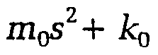
- a compensator in the internal feedback loop may provide double pole and double zero compensation:
- m 1 is the mass of the proof mass
- k 1 is the spring constant of the spring
- m Q is a nominal proof mass
- k 0 is a nominal spring constant
- the nominal proof mass and spring constant represent the accelerometer characteristics to which both accelerometers of a pair are to be matched in order that the two accelerometers are closely matched to each other.
- the compensation provided by the internal feedback loop may correct for the mass ratio (or Fo frequency ratio) mismatch between two paired accelerometers by providing the s 2 loop gain term as a mass compensator.
- the compensation may also correct for the spring ratio by providing a loop gain term which lumps together variations in pick-off gain, integrator capacitors and spring constant, as a spring stiffness k compensator.
- the components of the compensation network are typically resistors and capacitors. Variable components are introduced so that the break frequencies can be tuned over a +7-5% range to match the masses m and the spring stiffnesses k of the accelerometer pairs to better than 0.5%.
- the closed loop gain blocks are trimmed in pairs to match the time constants to within 0.5%.
- the invention is a method of matching accelerometer pairs, comprising the steps of : Testing the pair of accelerometers in back to back fixtures on a horizontal shaker which is aligned to the same vertical angle as in the GGI.
- a scale factor loop may be driven from the 0.25Hz signal or it may be adjusted manually while the excitation is applied.
- the external feedback path may provide the output signal, demodulated at the spin frequency ⁇ by a demodulator, to correct for mismatches in the strength B of the magnets in accelerometers.
- This feedback loop may also compensate for some part of the mismatches in proof mass and spring stiffness.
- figure 1 is a schematic diagram of a modified accelerometer pair embodying the present invention.
- Accelerometer 1 comprises a proof mass 2 suspended by a spring 3 in a magnetic field provided by magnet 4.
- the proof mass 2 is associated with a position sensor 5 which provides a feedback signal through feedback loop 6 to a reaction coil 7 that retains the proof mass 2.
- the current il flowing through coil 7 is taken as an output from output port 8.
- Feedback loop 6 includes a position sensor amplifier 9, a compensation network 10 and another amplifier 11 arranged in series.
- an external acceleration causes a force to be applied to the proof mass 2 within accelerometer 1. Any tendency to movement of the proof mass 2 causes a current to flow in feedback loop 6 and through coil 7.
- the current flowing through retaining coil 7 in the magnetic field provided by magnet 4 causes an equal and opposite force to be applied to the proof mass 2 to compensate for the tendency to movement.
- the current il flowing through the coil 7 is therefore a measure of the acceleration applied to the proof mass.
- the accelerometers are arranged in opposing pairs and the output il from accelerometer 1 is added to the output i2 from its paired accelerometer 12 and is combined with the output signals from the other pair of accelerometers in the GGI, in a summing amplifier 14, and the output is then filtered 15 to provide a signal to the instrument output 16.
- An external feedback path 17 provides the output signal, demodulated at the spin frequency ⁇ by demodulator 18, to be applied to a small electromagnet 19 associated with the magnet 4. This feedback signal corrects for mismatches between the strength B of the magnet 4 in accelerometer 1 and the strength of the magnet in accelerometer 12.
- This feedback loop will also compensate for some part of the mismatches in proof mass m and spring stiffness k; in particular the compensation matches the real component of the of mismatch at the spin frequency, but it cannot match at any other frequency or match the imaginary component of the mismatch.
- the dominant parameters affecting mismatch are the spring constant k differences.
- the dominant parameters are the proof mass m differences.
- the external feedback loop can be thought of as providing dynamic correction for the magnetic field ratio B/k where B is the magnetic field strength and k is the spring stiffness.
- the internal feedback path 6 includes high gains from the two amplifiers 9 and 11 to reduce errors in the accelerometer transfer function.
- m t is the mass of the proof mass
- k- t is the spring constant of the spring
- m 0 is a nominal proof mass
- Ao is a nominal spring constant.
- the components of the compensation network 10 are typically resistors and capacitors. Variable components are introduced so that the break frequencies can be tuned over a +/-5% range to match the masses m and the spring stiffnesses k of the accelerometer pairs to better than 0.5%.
- the closed loop gain blocks are trimmed in pairs to match the time constants to within 0.5%.
- the accelerometer pairs are then tested in back to back fixtures on a horizontal shaker.
- the accelerometers are selected on the basis of the best scale factor match at 0.5Hz and the lowest lateral sensitivity at 10Hz.
- Horizontal excitation at 0.25Hz, 1Hz and 10Hz (or higher) is input and the system response is detected with synchronous demodulation at these frequencies.
- a scale factor loop may be driven from the 0.25Hz signal or it may be adjusted manually while the excitation is applied.
- the mass compensation is adjusted to minimise the in phase (I) and the quadrature (Q) components of the signal at 10Hz, while the spring stiffness compensation is adjusted to minimise the components at 1Hz.
- the compensations are adjusted iteratively to achieve matches better than 0.5% since there is some interaction between the parameters.
Landscapes
- Physics & Mathematics (AREA)
- General Physics & Mathematics (AREA)
- Life Sciences & Earth Sciences (AREA)
- General Life Sciences & Earth Sciences (AREA)
- Geophysics (AREA)
- Electromagnetism (AREA)
- Gyroscopes (AREA)
- Pressure Sensors (AREA)
- Investigating Or Analyzing Materials By The Use Of Magnetic Means (AREA)
- Measurement Of Mechanical Vibrations Or Ultrasonic Waves (AREA)
Abstract
Description

Claims

Priority Applications (4)
| Application Number | Priority Date | Filing Date | Title |
|---|---|---|---|
| CA002293217A CA2293217A1 (en) | 1997-06-11 | 1998-06-11 | Gravity gradiometer accelerometers |
| BR9810253-2A BR9810253A (en) | 1997-06-11 | 1998-06-11 | Accelerometer, gravity gradient instrument and process of matching pairs of accelerometers |
| EP98923936A EP0988564A4 (en) | 1997-06-11 | 1998-06-11 | ACCELERATING KNIVES WITH DEVICE FOR DETERMINING THE HEAVY - GRADE GRADIENT |
| AU76318/98A AU753408C (en) | 1997-06-11 | 1998-06-11 | Gravity gradiometer accelerometers |
Applications Claiming Priority (4)
| Application Number | Priority Date | Filing Date | Title |
|---|---|---|---|
| AUPO7319 | 1997-06-11 | ||
| AUPO7319A AUPO731997A0 (en) | 1997-06-11 | 1997-06-11 | Improvements to gravity gradiometer accelerometers |
| AUPO7315 | 1997-06-12 | ||
| AUPO7315A AUPO731597A0 (en) | 1997-06-12 | 1997-06-12 | Improvements to gravity gradiometer accelerometers |
Publications (1)
| Publication Number | Publication Date |
|---|---|
| WO1998057196A1 true WO1998057196A1 (en) | 1998-12-17 |
Family
ID=25645446
Family Applications (1)
| Application Number | Title | Priority Date | Filing Date |
|---|---|---|---|
| PCT/AU1998/000442 Ceased WO1998057196A1 (en) | 1997-06-11 | 1998-06-11 | Gravity gradiometer accelerometers |
Country Status (6)
| Country | Link |
|---|---|
| US (2) | US5962782A (en) |
| EP (1) | EP0988564A4 (en) |
| BR (1) | BR9810253A (en) |
| CA (1) | CA2293217A1 (en) |
| ID (1) | ID26662A (en) |
| WO (1) | WO1998057196A1 (en) |
Cited By (3)
| Publication number | Priority date | Publication date | Assignee | Title |
|---|---|---|---|---|
| US6125698A (en) * | 1998-05-12 | 2000-10-03 | Lockheed Martin Corporation | System and process for optimizing gravity gradiometer measurements |
| US7263842B2 (en) | 2001-10-02 | 2007-09-04 | L'air Liquide, Societe Anonyme A Directoire Et Conseil De Surveillance Pour L'etude Et L'exploitation Des Procedes Georges Claude | Method and device for cooling a mass of a substance |
| RU2676217C1 (en) * | 2018-03-30 | 2018-12-26 | Федеральное государственное бюджетное образовательное учреждение высшего образования "Тульский государственный университет" (ТулГУ) | Compensation accelerometer |
Families Citing this family (15)
| Publication number | Priority date | Publication date | Assignee | Title |
|---|---|---|---|---|
| WO2002044757A2 (en) | 2000-11-28 | 2002-06-06 | Business Arts Inc. | Gravity gradiometry |
| US6833982B2 (en) * | 2001-05-03 | 2004-12-21 | Hitachi Global Storage Technologies Netherlands B.V. | Magnetic tunnel junction sensor with a free layer biased by longitudinal layers interfacing top surfaces of free layer extensions which extend beyond an active region of the sensor |
| CN100523709C (en) | 2002-02-14 | 2009-08-05 | Faro科技有限公司 | Portable coordinate measurement machine with articulated jib |
| US7073271B2 (en) * | 2002-02-14 | 2006-07-11 | Faro Technologies Inc. | Portable coordinate measurement machine |
| AUPS114702A0 (en) * | 2002-03-18 | 2002-04-18 | Bhp Billiton Innovation Pty Ltd | Enhancement of sensors for airborne operation |
| US7444867B2 (en) * | 2005-01-04 | 2008-11-04 | Bell Geospace, Inc. | Accelerometer and rate sensor package for gravity gradiometer instruments |
| US7236885B2 (en) * | 2005-07-08 | 2007-06-26 | Bell Geospace, Inc. | Method and system for geophysical data acquisition on an airship |
| CN100504443C (en) * | 2006-04-18 | 2009-06-24 | 赵鸣 | Vibration feature sensor |
| US8307710B2 (en) * | 2009-07-09 | 2012-11-13 | Honeywell International Inc. | Translational mass in-plane MEMS accelerometer |
| US9702992B2 (en) * | 2012-10-11 | 2017-07-11 | Silicon Audio Seismic, LLC | Closed loop control techniques for displacement sensors with optical readout |
| US9519076B2 (en) | 2014-02-20 | 2016-12-13 | Lockheed Martin Corporation | De-centralized control architecture for improved sensitivity of accelerometer-based gravity gradiometers |
| CN106646646B (en) * | 2016-12-16 | 2018-09-25 | 华中科技大学 | A kind of adjusting method of force balance type sensor scale factor |
| US10802087B2 (en) | 2018-09-11 | 2020-10-13 | Honeywell International Inc. | Spintronic accelerometer |
| US10871529B2 (en) | 2018-09-11 | 2020-12-22 | Honeywell International Inc. | Spintronic mechanical shock and vibration sensor device |
| US10876839B2 (en) | 2018-09-11 | 2020-12-29 | Honeywell International Inc. | Spintronic gyroscopic sensor device |
Citations (4)
| Publication number | Priority date | Publication date | Assignee | Title |
|---|---|---|---|---|
| US3926054A (en) * | 1974-11-11 | 1975-12-16 | Draper Lab Charles S | Gravity gradiometer |
| US4457077A (en) * | 1983-07-05 | 1984-07-03 | Standard Oil Company | Borehole gradiometer |
| US4841772A (en) * | 1987-12-03 | 1989-06-27 | University Of Maryland, College Park | Three-axis superconducting gravity gradiometer |
| US5341681A (en) * | 1987-11-27 | 1994-08-30 | Unisys Corporation | Stepped gravity gradiometer |
Family Cites Families (13)
| Publication number | Priority date | Publication date | Assignee | Title |
|---|---|---|---|---|
| US2674885A (en) * | 1949-08-17 | 1954-04-13 | Stanolind Oil & Gas Co | Gravity meter motion compensator |
| US3242736A (en) * | 1963-10-01 | 1966-03-29 | Bell Aerospace Corp | Altimeter system |
| DE1623389B1 (en) * | 1967-04-27 | 1971-07-29 | Askania Gmbh | GRAVIMETER |
| DE1908232C3 (en) * | 1969-02-14 | 1974-10-17 | Siemens Ag, 1000 Berlin Und 8000 Muenchen | Gravimeter |
| US3633003A (en) * | 1970-02-11 | 1972-01-04 | Us Navy | Off-leveling computer |
| CA1085645A (en) * | 1978-07-06 | 1980-09-16 | Henry O. Baker | Portable accelerometer |
| US4386318A (en) * | 1980-09-26 | 1983-05-31 | Her Majesty The Queen In Right Of Canada, As Represented By The Minister Of National Defence | Method and apparatus to compensate a gradiometer having first and second unwanted terms |
| FR2495328B1 (en) * | 1980-11-28 | 1986-04-11 | Onera (Off Nat Aerospatiale) | IMPROVEMENTS ON ELECTROSTATIC ACCELEROMETERS |
| FR2534689A1 (en) * | 1982-10-14 | 1984-04-20 | Nal Expl Oceans Centre | APPARATUS FOR MEASURING CHARACTERISTICS OF THE WAVE AT SEA |
| GB2146776B (en) * | 1983-09-16 | 1986-07-30 | Ferranti Plc | Accelerometer systems |
| CA2104180C (en) * | 1993-08-16 | 1999-08-10 | Jerry R. Panenka | Laplace gravity gradiometer |
| CA2210397A1 (en) * | 1995-01-27 | 1996-08-01 | Poul Johansen Development A/S | Vibration conveyors |
| US6075754A (en) * | 1997-04-08 | 2000-06-13 | Vanzandt; Thomas R. | Single-coil force balance velocity geophone |
-
1997
- 1997-07-03 US US08/888,036 patent/US5962782A/en not_active Expired - Lifetime
-
1998
- 1998-06-11 WO PCT/AU1998/000442 patent/WO1998057196A1/en not_active Ceased
- 1998-06-11 CA CA002293217A patent/CA2293217A1/en not_active Abandoned
- 1998-06-11 ID IDW20000044A patent/ID26662A/en unknown
- 1998-06-11 BR BR9810253-2A patent/BR9810253A/en not_active IP Right Cessation
- 1998-06-11 EP EP98923936A patent/EP0988564A4/en not_active Withdrawn
-
1999
- 1999-10-05 US US09/415,140 patent/US6575029B1/en not_active Expired - Fee Related
Patent Citations (4)
| Publication number | Priority date | Publication date | Assignee | Title |
|---|---|---|---|---|
| US3926054A (en) * | 1974-11-11 | 1975-12-16 | Draper Lab Charles S | Gravity gradiometer |
| US4457077A (en) * | 1983-07-05 | 1984-07-03 | Standard Oil Company | Borehole gradiometer |
| US5341681A (en) * | 1987-11-27 | 1994-08-30 | Unisys Corporation | Stepped gravity gradiometer |
| US4841772A (en) * | 1987-12-03 | 1989-06-27 | University Of Maryland, College Park | Three-axis superconducting gravity gradiometer |
Non-Patent Citations (4)
| Title |
|---|
| DERWENT ABSTRACT, Accession No. 96-250143/25, Class S03; & RU,C,2 046 380 (PERM POLY) 20 October 1995. * |
| DERWENT ABSTRACT, Accession No. 97-041553/04, Class S03; & RU,C,2 059 272 (PERM POLY) 27 April 1996. * |
| DERWENT ABSTRACT, Accession No. B6043D/08, Class S03; & SU,A,741 221 (BELENKII V A) 15 June 1980. * |
| See also references of EP0988564A4 * |
Cited By (5)
| Publication number | Priority date | Publication date | Assignee | Title |
|---|---|---|---|---|
| US6125698A (en) * | 1998-05-12 | 2000-10-03 | Lockheed Martin Corporation | System and process for optimizing gravity gradiometer measurements |
| US6152226A (en) * | 1998-05-12 | 2000-11-28 | Lockheed Martin Corporation | System and process for secondary hydrocarbon recovery |
| US6467543B1 (en) | 1998-05-12 | 2002-10-22 | Lockheed Martin Corporation | System and process for secondary hydrocarbon recovery |
| US7263842B2 (en) | 2001-10-02 | 2007-09-04 | L'air Liquide, Societe Anonyme A Directoire Et Conseil De Surveillance Pour L'etude Et L'exploitation Des Procedes Georges Claude | Method and device for cooling a mass of a substance |
| RU2676217C1 (en) * | 2018-03-30 | 2018-12-26 | Федеральное государственное бюджетное образовательное учреждение высшего образования "Тульский государственный университет" (ТулГУ) | Compensation accelerometer |
Also Published As
| Publication number | Publication date |
|---|---|
| BR9810253A (en) | 2000-09-19 |
| US6575029B1 (en) | 2003-06-10 |
| US5962782A (en) | 1999-10-05 |
| CA2293217A1 (en) | 1998-12-17 |
| EP0988564A4 (en) | 2007-06-20 |
| EP0988564A1 (en) | 2000-03-29 |
| ID26662A (en) | 2001-01-25 |
Similar Documents
| Publication | Publication Date | Title |
|---|---|---|
| US5962782A (en) | Gravity gradiometer accelerometers | |
| CA2293219C (en) | Gravity gradiometer | |
| JP4331211B2 (en) | Method to reduce bias error in vibrating structure gyroscope | |
| US7159441B2 (en) | Cloverleaf microgyroscope with electrostatic alignment and tuning | |
| Saukoski et al. | Zero-rate output and quadrature compensation in vibratory MEMS gyroscopes | |
| US5577073A (en) | Frequency and phase-locked two-phase digital synthesizer | |
| US7181967B2 (en) | Enhancement of sensors for airborne operation | |
| US6658935B1 (en) | Complemented absolute/relative full-tensor gravity gradiometer system | |
| Agafonov et al. | Electrochemical seismometers of linear and angular motion | |
| US5444641A (en) | Admittance-parameter estimator for a piezoelectric resonator in an oscillator circuit | |
| JPS6110774A (en) | Accelerometer device | |
| US9891290B2 (en) | Offset suppression in micromachined Lorentz force magnetic sensor by current chopping | |
| IL189911A (en) | Inertial measurement system and method with sensor bias cancellation | |
| Hiller et al. | Noise contributions in a closed-loop MEMS gyroscope for automotive applications | |
| US5786895A (en) | Means and method for active dispersion equalization of a multioscillator ring laser gyroscope | |
| Metzger | Recent gravity gradiometer developments | |
| Yu et al. | Online error compensation of moving-base rotating accelerometer gravity gradiometer | |
| CN116295541B (en) | A feedback sensing method and device based on a weakly coupled resonant sensor | |
| AU753408C (en) | Gravity gradiometer accelerometers | |
| Metzger et al. | Satellite borne gravity gradiometer study | |
| JP2003279607A (en) | Automatic balance circuit for impedance measurement | |
| RU2000100953A (en) | GRAVITY GRADIOMETER ACCELEROMETER | |
| Aslan et al. | No-Drift Mode-Matched Ring Gyroscope with On-Chip Stress and Temperature Calibration | |
| SU840945A1 (en) | Device for integrating ac envelope | |
| SU1721565A1 (en) | Device for calibrating seismometers |
Legal Events
| Date | Code | Title | Description |
|---|---|---|---|
| AK | Designated states |
Kind code of ref document: A1 Designated state(s): AL AM AT AU AZ BA BB BG BR BY CA CH CN CU CZ DE DK EE ES FI GB GE GH GM GW HU ID IL IS JP KE KG KP KR KZ LC LK LR LS LT LU LV MD MG MK MN MW MX NO NZ PL PT RO RU SD SE SG SI SK TJ TM TR TT UA UG UZ VN YU ZW |
|
| AL | Designated countries for regional patents |
Kind code of ref document: A1 Designated state(s): GH GM KE LS MW SD SZ UG ZW AM AZ BY KG KZ MD RU TJ TM AT BE CH CY DE DK ES FI FR GB GR IE IT LU MC NL PT SE BF BJ CF CG CI CM GA GN ML MR NE SN TD TG |
|
| DFPE | Request for preliminary examination filed prior to expiration of 19th month from priority date (pct application filed before 20040101) | ||
| 121 | Ep: the epo has been informed by wipo that ep was designated in this application | ||
| ENP | Entry into the national phase |
Ref document number: 2293217 Country of ref document: CA Kind code of ref document: A Ref document number: 2293217 |
|
| WWE | Wipo information: entry into national phase |
Ref document number: 76318/98 Country of ref document: AU |
|
| WWE | Wipo information: entry into national phase |
Ref document number: 1998923936 Country of ref document: EP |
|
| NENP | Non-entry into the national phase |
Ref document number: 1999501144 Country of ref document: JP |
|
| WWP | Wipo information: published in national office |
Ref document number: 1998923936 Country of ref document: EP |
|
| REG | Reference to national code |
Ref country code: DE Ref legal event code: 8642 |
|
| WWG | Wipo information: grant in national office |
Ref document number: 76318/98 Country of ref document: AU |