WO2001020595A1 - Codeur/decodeur vocal - Google Patents
Codeur/decodeur vocal Download PDFInfo
- Publication number
- WO2001020595A1 WO2001020595A1 PCT/JP1999/004991 JP9904991W WO0120595A1 WO 2001020595 A1 WO2001020595 A1 WO 2001020595A1 JP 9904991 W JP9904991 W JP 9904991W WO 0120595 A1 WO0120595 A1 WO 0120595A1
- Authority
- WO
- WIPO (PCT)
- Prior art keywords
- signal
- codebook
- pulse
- pitch lag
- input signal
- Prior art date
- Legal status (The legal status is an assumption and is not a legal conclusion. Google has not performed a legal analysis and makes no representation as to the accuracy of the status listed.)
- Ceased
Links
Classifications
-
- G—PHYSICS
- G10—MUSICAL INSTRUMENTS; ACOUSTICS
- G10L—SPEECH ANALYSIS TECHNIQUES OR SPEECH SYNTHESIS; SPEECH RECOGNITION; SPEECH OR VOICE PROCESSING TECHNIQUES; SPEECH OR AUDIO CODING OR DECODING
- G10L19/00—Speech or audio signals analysis-synthesis techniques for redundancy reduction, e.g. in vocoders; Coding or decoding of speech or audio signals, using source filter models or psychoacoustic analysis
- G10L19/04—Speech or audio signals analysis-synthesis techniques for redundancy reduction, e.g. in vocoders; Coding or decoding of speech or audio signals, using source filter models or psychoacoustic analysis using predictive techniques
- G10L19/08—Determination or coding of the excitation function; Determination or coding of the long-term prediction parameters
- G10L19/09—Long term prediction, i.e. removing periodical redundancies, e.g. by using adaptive codebook or pitch predictor
-
- G—PHYSICS
- G10—MUSICAL INSTRUMENTS; ACOUSTICS
- G10L—SPEECH ANALYSIS TECHNIQUES OR SPEECH SYNTHESIS; SPEECH RECOGNITION; SPEECH OR VOICE PROCESSING TECHNIQUES; SPEECH OR AUDIO CODING OR DECODING
- G10L19/00—Speech or audio signals analysis-synthesis techniques for redundancy reduction, e.g. in vocoders; Coding or decoding of speech or audio signals, using source filter models or psychoacoustic analysis
- G10L19/04—Speech or audio signals analysis-synthesis techniques for redundancy reduction, e.g. in vocoders; Coding or decoding of speech or audio signals, using source filter models or psychoacoustic analysis using predictive techniques
-
- G—PHYSICS
- G10—MUSICAL INSTRUMENTS; ACOUSTICS
- G10L—SPEECH ANALYSIS TECHNIQUES OR SPEECH SYNTHESIS; SPEECH RECOGNITION; SPEECH OR VOICE PROCESSING TECHNIQUES; SPEECH OR AUDIO CODING OR DECODING
- G10L19/00—Speech or audio signals analysis-synthesis techniques for redundancy reduction, e.g. in vocoders; Coding or decoding of speech or audio signals, using source filter models or psychoacoustic analysis
- G10L19/04—Speech or audio signals analysis-synthesis techniques for redundancy reduction, e.g. in vocoders; Coding or decoding of speech or audio signals, using source filter models or psychoacoustic analysis using predictive techniques
- G10L19/08—Determination or coding of the excitation function; Determination or coding of the long-term prediction parameters
- G10L19/10—Determination or coding of the excitation function; Determination or coding of the long-term prediction parameters the excitation function being a multipulse excitation
- G10L19/107—Sparse pulse excitation, e.g. by using algebraic codebook
-
- G—PHYSICS
- G10—MUSICAL INSTRUMENTS; ACOUSTICS
- G10L—SPEECH ANALYSIS TECHNIQUES OR SPEECH SYNTHESIS; SPEECH RECOGNITION; SPEECH OR VOICE PROCESSING TECHNIQUES; SPEECH OR AUDIO CODING OR DECODING
- G10L19/00—Speech or audio signals analysis-synthesis techniques for redundancy reduction, e.g. in vocoders; Coding or decoding of speech or audio signals, using source filter models or psychoacoustic analysis
- G10L19/04—Speech or audio signals analysis-synthesis techniques for redundancy reduction, e.g. in vocoders; Coding or decoding of speech or audio signals, using source filter models or psychoacoustic analysis using predictive techniques
- G10L19/16—Vocoder architecture
- G10L19/18—Vocoders using multiple modes
-
- G—PHYSICS
- G10—MUSICAL INSTRUMENTS; ACOUSTICS
- G10L—SPEECH ANALYSIS TECHNIQUES OR SPEECH SYNTHESIS; SPEECH RECOGNITION; SPEECH OR VOICE PROCESSING TECHNIQUES; SPEECH OR AUDIO CODING OR DECODING
- G10L19/00—Speech or audio signals analysis-synthesis techniques for redundancy reduction, e.g. in vocoders; Coding or decoding of speech or audio signals, using source filter models or psychoacoustic analysis
- G10L2019/0001—Codebooks
- G10L2019/0007—Codebook element generation
- G10L2019/0008—Algebraic codebooks
Definitions
- the present invention relates to a speech encoding and decoding apparatus for encoding / decoding speech at a low bit rate of 4 kbit / s or less, and more particularly to an AbS (Analysis fby-Synthesis) type vector quantization.
- the present invention relates to an audio encoding and audio decoding device that encodes and decodes audio at a low bit rate.
- AbS-type speech coding typified by Code Excited Linear Predictive Coding (CELP), achieves high information compression efficiency while maintaining speech quality in digital mobile communications and corporate communication systems. It is expected as a method to realize it.
- CELP Code Excited Linear Prediction
- Figure 15 shows the principle diagram of CELP.
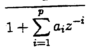
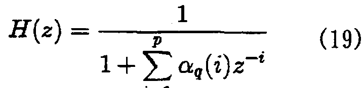
- the human vocal tract is LPC synthesis filter expressed by ⁇ ( ⁇ )
- the input to H ( Z ) sound source signal
- CELP extracts the filter coefficients of the LPC synthesis filter and the pitch period component and the noise component of the excitation signal, and transmits the quantization index obtained by quantizing these, instead of transmitting the input voice signal to the decoder side as it is. By doing Achieving high information compression.
- Fig. 16 is a diagram explaining the quantization method. A large number of sets of quantized LPC coefficients are stored in the quantization table 2a corresponding to the index numbers 1 to n. Distance calculator 2 b is
- the minimum distance index detector 2c finds q that minimizes the distance d, and transmits the index q to the decoder side.
- the LPC synthesis filter constituting the hearing weighted synthesis filter 3 is given by the following equation (2).
- CELP the excitation signal is divided into two components, a pitch period component and a noise component.
- the adaptive codebook 4 that stores the past excitation signal sequence is used to quantize the pitch period component, and the algebraic codebook is used to quantize the noise component. Or a noise codebook.
- a typical CELP-type speech coding scheme using two codebooks, adaptive codebook 4 and algebraic codebook 5, as excitation codebooks will be described.
- Adaptive codebook 4 outputs N samples of excitation signals (referred to as periodic signals) sequentially delayed by one pitch (one sample) corresponding to indices 1 to L.
- the adaptive codebook search is performed in the following procedure.
- the pitch lag L representing the delay from the current frame is set to an initial value Lo (for example, 20).
- a past periodic signal (adaptive code vector) corresponding to the delay L is extracted from the adaptive codebook 4. That is, out takes adaptive code base vector P L indicated index L, obtaining the output AP L obtained by inputting the hearing weighting synthesis filter 3.
- A is the impulse response of the auditory weighting synthesis filter 3 composed of a cascade connection of the auditory weighting filter W (z) and the LPC synthesis filter Hq (z).
- Any filter can be used as an auditory weighting filter.
- gh g 2 is a parameter for adjusting the characteristics of the weighting filter.
- the search range of the lag L is arbitrary, but when the sampling frequency of the input signal is 8 k3 ⁇ 4, the range of the lag can be set to 20 to 147.
- Algebraic codebook 5 is composed of a plurality of pulses having an amplitude of 1 or -1.
- Fig. 18 shows the pulse positions when the frame length is 40 samples.
- a pulse signal having +1 or 11 pulses at each sample point is sequentially output as a noise component.
- basically four pulses per frame are arranged.
- Figure 19 is an explanatory diagram of the sample points assigned to each pulse system group 1-4.
- the optimum adaptive codebook output and the optimum pitch gain determined by the adaptive codebook search from the input signal X is generated by the following equation.
- the error power evaluator 7 searches for k according to the following equation, which is equivalent to searching for C k that maximizes (AC k ) T (AC k ), that is, k.
- Equation (10) is obtained by the following equation.
- the gains opt and ⁇ opt are quantized.
- the method of quantizing the gain is arbitrary, and a method such as scalar quantization or vector quantization can be used.
- ⁇ and ⁇ are quantized and the quantization index of the gain is transmitted to the decoder.
- the output information selection unit 9 includes (1) the quantization index of the LPC coefficient, (2) the pitch lag Lopt, (3) the algebraic codebook index (pulse signal identification data), and (4) the gain Transmit the quantized index to the decoder.
- the state of the adaptive codebook 4 is updated before processing the input signal of the next frame.
- the oldest (oldest) frame of the excitation signal in the adaptive codebook is discarded by the frame length, and the latest excitation signal obtained in the current frame is stored by the frame length.
- the initial state of the adaptive codebook 4 is a zero state, that is, the amplitude of all samples is zero.
- the CELP method can efficiently compress voice by modeling the voice generation process and quantizing and transmitting characteristic parameters of the model.
- CELP (and its improvement) can realize high-quality reproduced sound at a bit rate of about 8 to 16 kbit / s.
- ITU-T Recommendation G.729 (CS-A CELP) can achieve the same sound quality as 32 kbit / s ADPCM under the low bit rate condition of 8 kbit / s.
- CS-A CELP ITU-T Recommendation G.729
- the frame length of CS-ACELP is 5 ms (40 samples), and as described above, the noise component of the sound source signal is vector-quantized by 17 bits per frame.
- Figure 20 shows an example of pulse arrangement when four pulses are set up in a 10 msec frame.
- pulses of the first to third pulse systems are each represented by 5 bits
- pulses of the fourth pulse system are represented by 6 bits.
- 21 bits are required. In other words, when using the algebraic codebook, even if the frame length is simply doubled to 10 ms, unless the number of pulses per frame is reduced, the number of pulse combinations increases by the amount of increased pulse positions. Therefore, the number of quantization bits also increases.
- the only way to reduce the number of bits of the algebraic codebook index to 17 bits is to reduce the number of pulses, for example, as shown in FIG.
- the number of pulses per frame is set to three or less, the quality of reproduced sound is rapidly deteriorated. This phenomenon can be easily understood qualitatively. In other words, if 4 pulses are generated per frame when the frame book is 5 msec (Fig. 18), there are 8 pulses at 10 msec. On the other hand, if three pulses are generated per frame when the frame book is 10 msec (Fig. 21), there are naturally only three pulses at 10 msec. For this reason, the noise characteristics of the sound source signal to be represented by the algebraic codebook cannot be sufficiently expressed, and the quality of the reproduced sound is degraded.
- an object of the present invention is to reduce the bit rate and enable high-quality sound reproduction.
- the encoder consists of (1) LPC coefficient quantization index, (2) adaptive codebook pitch lag L op (3) algebraic codebook index (pulse signal specific data), and (4) gain quantum Transmit the encryption index to the decoder.
- 8 bits are required to transmit the pitch lag, and if the pitch lag is not sent, the number of bits for expressing the algebraic codebook index can be increased accordingly. That is, the number of pulses included in the pulse signal output from the algebraic codebook can be increased, and high-quality speech code transmission and high-quality reproduction can be performed.
- the pitch period changes slowly in the stationary part of speech. In the stationary part, the pitch lag of the current frame is considered to be the same as the pitch lag of the past (for example, immediately before) frame. Playback audio quality hardly deteriorates.
- an encoding mode 1 using the pitch lag obtained from the input signal of the current frame and an encoding mode 2 using the pitch lag obtained from the input signal of the past frame are prepared.
- the encoder re-encodes each frame in encoding mode 1 and encoding mode 2, respectively, and transmits a code encoded in a mode that can reproduce the input signal more accurately to the decoder. In this way, the bit rate can be reduced and high-quality audio can be reproduced.
- an encoding mode 1 using a pitch lag obtained from the input signal of the current frame and an encoding mode 2 using a pitch lag obtained from the input signal of the past frame are prepared, and the first mode having a small number of pulses in the encoding mode 1 is provided.
- An algebraic codebook is used, and in encoding mode 2, a second algebraic codebook having more pulses than the first codebook is used.
- an optimal mode is determined based on the properties of the input signal, for example, the periodicity of the input signal, and encoding is performed based on the determined mode. In this way, the bit rate can be reduced and high-quality audio can be reproduced.
- FIG. 1 is a first schematic explanatory diagram of the present invention.
- FIG. 2 is an example of a pulse arrangement of the algebraic codebook 0.
- FIG. 3 is an example of a pulse arrangement in the algebraic codebook 1.
- FIG. 4 is a second schematic explanatory diagram of the present invention.
- FIG. 5 shows an example of a pulse arrangement in the algebraic codebook 2.
- FIG. 6 is a configuration diagram of a first embodiment of the encoding device.
- FIG. 7 is a configuration diagram of a second embodiment of the encoding device.
- FIG. 8 shows a processing procedure of the mode determination unit.
- FIG. 9 is a configuration diagram of a third embodiment of the encoding device.
- FIG. 10 shows a pulse arrangement example of each algebraic codebook used in the third embodiment.
- FIG. 11 is a conceptual diagram of pitch periodization.
- FIG. 12 is a configuration diagram of a fourth embodiment of the encoding device.
- FIG. 13 is a configuration diagram of a first embodiment of a decoding device.
- FIG. 14 is a configuration diagram of a second embodiment of the decoding device.
- Figure 15 shows the principle of CELP.
- FIG. 16 is an explanatory diagram of the quantization method.
- FIG. 17 is an explanatory diagram of the adaptive codebook.
- Fig. 18 shows an example of pulse arrangement in the algebraic codebook.
- FIG. 19 is an explanatory diagram of sample points assigned to each pulse system group.
- FIG. 20 shows an example in which four pulses are set in a frame of 10 ms e c.
- FIG. 21 shows an example in which three pulses are set in a 10 ms e c frame.
- the present invention provides a first encoding mode (mode 0) using a pitch lag obtained from an input signal of a current frame as a pitch lag of a current frame, and a second encoding mode using a pitch lag obtained from a past input signal, for example, one frame before.
- the coding mode (mode 1) is prepared. In mode 0, an algebraic codebook with a smaller number of pulses is used. In mode 1, an algebraic codebook with a larger number of pulses is used than in the algebraic codebook of mode 0. Which mode is used for encoding depends on whether the sound can be faithfully reproduced. Since the number of pulses increases in mode 1, the noise component of the audio signal can be represented more faithfully than in mode 0.
- the input signal vector X is input to the LPC analysis unit 11 and the LPC coefficient a (i) , ..., ⁇ ).
- ⁇ is the LPC analysis order.
- the number of dimensions of X is the same as the number N of samples forming a frame.
- the dimension number of the revector is assumed to be N unless otherwise specified.
- the LPC synthesis filter 13 representing the vocal tract characteristics is composed of aq (i), and its transfer function is It is represented by
- the first code section 14 operating in mode 0 is composed of an adaptive codebook (adaptive codebook 0) 14 a, an algebraic structure codebook (algebraic codebook 0) 14 b, and gain multipliers 14 c, 1 4 d and power!]
- the calculator has 14 e.
- the second code section 15 operating in mode 1 is composed of an adaptive codebook (adaptive codebook 1) 15a, an algebraic structure codebook (algebraic codebook 1) 15b, and a gain multiplier 1 5c, 15d and an adder 15e are provided.
- the pulse arrangement of the algebraic structure codebook 14 b in the first code unit 14 is as shown in FIG.
- the algebraic structure codebook 1 4 b is composed of N
- the sample point is divided into three pulse system groups 0 to 2 and one sample point is extracted from each pulse system group.
- a pulse signal having a positive pulse is sequentially output as a noise component.
- Kicking pulse position and pulse 6 bits required Do Re to represent the polarity of the need to Totanore 17 bits to identify the pulsed signal Ninari, the number of combinations m is 2 1 7 copies Li.
- the pulse arrangement of the algebraic structure codebook 15b in the second code section 15 is as shown in FIG. That is, the algebraic structure codebook 15b is composed of N
- the first encoding unit 14 which is a communication has the same configuration as that of normal CELP, and the codebook search is performed in the same manner as CELP. That is, the pitch lag L is changed within a predetermined range (for example, 20 to 147) in the first adaptive codebook 14a, and the adaptive codebook output P at each pitch lag.
- (L) is input to the LPC synthesis filter 13 via the mode switching unit 16, and the calculation unit 17 calculates the error power between the LPC synthesis filter output and the input signal X, and outputs the error power evaluation unit 1 8 is the optimal pitch lag Lag and the optimal pitch gain
- the error power between the filter output and the input signal X is calculated, and the error power evaluator 18 is an index I for identifying the pulse signal having the minimum error power.
- m 2 17 represents the size of the algebraic codebook 14 b (total number of combinations of Panoress).
- Mode 1 differs from mode 0 in that no adaptive codebook search is performed.
- the pitch period changes slowly in the stationary part of speech. Even if the pitch lag is the same as that of the previous frame (for example, the previous frame), the reproduced audio quality is hardly degraded. In such a case, there is no need to send the pitch lag to the decoder, so that there is a margin for the number of bits (for example, 8 bits) necessary for encoding the pitch lag. Therefore, these 8 bits are used to represent the algebraic codebook index.
- the pulse arrangement of the algebraic codebook 15b can be made as shown in FIG. 3, and the number of pulses of the pulse signal can be increased.
- CELP if the number of bits transmitted in the algebraic codebook (or noise codebook, etc.) is increased, the quality of replayed speech, which can express complex sound source signals, is improved.
- the second encoding unit 15 does not perform the adaptive codebook search, regards the optimal pitch lag lag_old obtained in the past frame (for example, the previous frame) as the optimal lag of the current frame, and determines the optimal pitch gain at that time. Ask. Next, the second encoder 15 performs an algebraic codebook search using the algebraic codebook 15b in the same manner as the algebraic codebook search in the first encoder 14, and obtains the pulse '14 signal with the minimum error power. The optimal index I and the optimal gain y to be specified are determined.
- the error power evaluator 18 calculates each error power between the sound source signal vectors e 0 and ei and the input signal.
- the mode determination unit 19 compares the error power input from the error power evaluation unit 18 and determines the mode with the smaller error power as the mode to be used finally.
- the output information selection unit 20 outputs the mode information and the LPC quantum Select the quantization index, pitch lag, algebraic codebook index and gain quantization index of the mode to be used, and transmit them to the decoder.
- the state of the adaptive codebook is updated before processing the input signal of the next frame.
- the state update Discard the source signal of the oldest (oldest) frame by the frame length, and store the latest source signal ex (source signal e. Or ei ) obtained in the current frame. Note that the initial state of the adaptive code book is set to zero.
- the mode to be finally used is determined after performing the adaptive codebook search / algebraic codebook search for all modes (mode 0, mode 1). It is also possible to determine which mode to adopt in accordance with, and execute adaptive codebook search / algebraic codebook search in one of the adopted modes to perform encoding.
- two adaptive codebooks are used.However, since two identical codebooks store the same excitation signal in the past, they may be implemented with one adaptive codebook. .
- FIG. 4 is a second schematic explanatory view of the present invention, and the same parts as those in FIG. 1 are denoted by the same reference numerals. The different point is the configuration of the second encoding unit 15.
- the algebraic codebook 15 b of the second code part 15 (1) the first algebraic structure codebook 15 and (2) the second algebraic structure codebook 15 Algebraic structure Codebook 1 5 b 2 is provided.
- N 80
- a pulse signal having a positive or negative pulse is sequentially output at sample points taken out of the group one by one.
- the algebraic codebook switching unit 15 f sets the value of the past pitch lag L ag—old If M is larger than M, the pulse signal output from the first algebraic structure codebook 15 is selected.If M is smaller than M, the pulse signal output from the second algebraic structure codebook 15 b 2 is selected. .
- the pitch periodizer 15 g uses the pulse of the second algebraic codebook 15 b 2 A pitch period process for repeatedly outputting the sex signal pattern is performed.
- the amount of information for transmitting the re-pitch lag by using the past pitch lag is deleted.
- mode 1 in which the amount of information in the algebraic codebook is increased, high-quality reproduced speech quality can be obtained in the stationary part of speech such as voiced parts. Further, by switching between mode 0 and mode 1 in accordance with the characteristics of the input signal, it is possible to obtain high-quality reproduced voice quality for input voices having various characteristics.
- FIG. 6 is a block diagram of a first embodiment of the speech encoding apparatus of the present invention, which has a speech encoder composed of two modes, mode 0 and mode 1.
- the LPC analysis unit 11 and LPC coefficient quantization unit 12 that are common to mode 0 and mode 1 will be described.
- the input signal is divided into frames of a fixed length of about 5 to 10 msec, and the encoding process is performed in frame units.
- the number of LPC analyzes is ⁇ .
- the method of quantizing LPC coefficients is arbitrary, and methods such as scalar quantization and vector quantization can be used. Also, instead of directly quantizing the LPC coefficient, it is first converted to another parameter with excellent quantization characteristics, such as the k parameter (reflection coefficient) and LSP (line spectrum pair). It may be quantized.
- the transfer function H (z) of the LPC synthesis filter 13a that forms the auditory weighted synthesis filter 13 is
- the first encoding unit 14 operating according to mode 0 has the same configuration as ordinary CELP, and has an adaptive codebook 14a, an algebraic codebook 14b, gain multiplication units 14c and 14d, an adder 14e, and a gain. Equipped with a quantization unit 14 h, (1) finds the optimal pitch lag Lag, (2) algebraic codebook index index-C0, and (3) gain index index-gO.
- the search method for the adaptive codebook 14a and the search method for the algebraic codebook 14b in mode 0 are the same as the methods described in (A) in the outline of the present invention.
- the gain quantizer 14h quantizes the pitch gain and the algebraic codebook gain.
- the quantization method is arbitrary, and scalar quantization or vector quantization can be used.
- the pitch gain which is quantized) 8 0, the quantized gain of the algebraic codebook 14 b gamma.
- the optimal sound source vector e 0 of mode 0 is
- the second encoding unit 15 operating according to the mode 1 does not perform the adaptive codebook search.
- the optimal pitch lag searched for in the previous frame is used as the optimal pitch lag for the current frame.
- the adaptive codebook 15a no search processing is performed, and the optimum pitch lag Lag-old obtained in the past frame (for example, the previous frame) is used as the optimum lag of the current frame to obtain the optimum pitch gain i8.
- the optimum pitch gain can be calculated by equation (6). As described above, since it is not necessary to transmit the pitch lag to the decoder in mode 1, the number of bits required for the pitch lag transmission (for example, 8 bits per frame) is divided into the quantization of the algebraic codebook index. You can guess.
- the output of adaptive codebook 15a determined in mode 1 is P i
- the output of algebraic codebook 15b is C i
- the quantized pitch gain is the quantized value of algebraic codebook 15b.
- This sound source vector ei is input to the weighting filter 13b ', and its output is input to the LPC synthesis filter 13a' to create a weighted synthesized output syiu.
- the error power evaluation section 18 ' calculates the error power errl between the input signal X and the weighted composite output syiu and inputs the error power errl to the mode determination section 19.
- the mode determination unit 19 compares errO and errl, and finally determines the one with smaller error power as the use mode.
- the selected mode (0 or 1).
- the output information selection unit 20 selects a pitch lag Lag—opt, an algebraic codebook index Index— (:, a gain index Index_g, based on the use mode, and outputs the mode information and the LPC index to these.
- the final coded data (transmission information) is created by adding information and transmitted.
- the state of the adaptive codebook is updated before processing the input signal of the next frame.
- the initial state of the adaptive codebook is a zero state, that is, the amplitude of all samples is zero.
- FIG. 6 Although the embodiment of FIG. 6 has been described using two adaptive codebooks 14a and 15a, the two adaptive codebooks store exactly the same excitation signal in the past. It may be realized by a book. Further, in the embodiment of FIG. 6, two weighting filters, two LPC synthesis filters, and two error power evaluators are used, but each may be shared and used as one.
- a non-stationary part such as a unvoiced part or a transient part performs the same encoding processing as the conventional CELP
- a stationary part of the voice such as a voiced part has a mode (mode 1).
- FIG. 7 is a configuration diagram of a second embodiment of the speech encoding apparatus, and the same parts as those in the first embodiment of FIG.
- an adaptive codebook search / algebraic codebook search is performed in each mode, a mode having a smaller error is determined as a mode to be finally used, and a pitch lag L ag ⁇ op t, algebraic codebook index Index-C, and gain index Index-g were selected and transmitted to the decoder.
- the characteristics of the input signal are examined before searching, and the mode to be used is determined according to the characteristics, and the adaptive codebook search / algebraic code is used in one of the adopted modes. Book Run and encode.
- the difference between the second embodiment and the first embodiment is that (1) A mode determination unit 31 is provided to check the properties of the input signal X before searching the codebook, and determine which mode to use depending on the properties.
- a mode output selection unit 32 is provided to select the outputs of the encoding units 14 and 15 corresponding to the adopted mode and input them to the weighting filter 13b.
- the output information selection unit 20 selects and transmits information to be transmitted to the decoder based on the mode information input from the mode determination unit 31,
- the mode determination unit 31 checks the properties of the input signal X, and generates mode information indicating which mode 0 or mode 1 is to be adopted according to the properties. If mode 0 is determined to be optimal, the mode information is set to 0. If mode 1 is determined to be optimal, the mode information is set to 1. Based on this determination result, the mode output selector 32 selects the output of the first encoder 14 or the second encoder 15. As a mode determination method, a method of detecting a change in the open loop plug can be used.
- N is the number of samples constituting one frame.
- the lag k at which the autocorrelation function R (k) is maximized is determined (step 102).
- the lag k at which the autocorrelation function R (k) is maximized is called an open loop plug and is represented by.
- the open loop plug obtained in the same way in the previous frame is referred to as L-o Id. Then, the difference between the open loop plug L-o Id of the previous frame and the open loop plug L of the current frame
- (L-old-L) is calculated (step 103). If (L-old-L) is larger than a predetermined threshold, the periodicity of the input voice is considered to have changed greatly, and the mode information is set to 0. . On the other hand, if (L-old-L) is smaller than the threshold, it is considered that the periodicity of the input speech has not changed from the previous frame, and the mode information is set to 1. Top 104). Thereafter, the above processing is repeated for each frame. After completion of the mode determination, the open loop plug L obtained in the current frame is retained as L-old for mode determination in the next frame.
- the mode output selector 32 selects terminal 0 if the mode information is 0, and selects terminal 1 if the mode information is 1. Therefore, unlike the first embodiment, the two modes do not operate simultaneously in the same frame.
- the first encoding unit 14 searches the adaptive codebook 14 a and the algebraic codebook 14 b, and thereafter, obtains a gain quantizer 14. h is pitch gain. And algebraic codebook gainers. Is performed. At this time, the second encoding unit according to mode 1 does not operate.
- the second encoding unit 15 does not perform the adaptive codebook search, and the optimal pitch lag 1 ag— obtained in the past frame (for example, the previous frame).
- o 1 d is regarded as the optimal lag of the current frame, and the optimal pitch gain ⁇ i at that time is obtained.
- the second encoding unit 15 performs an algebraic codebook search using the algebraic codebook 15b, and determines an optimal index Ie and an optimal gain yi for specifying a pulse signal having the minimum error power.
- the gain quantizer 15h performs quantization of the pitch gain and the algebraic codebook gain. At this time, the first sign section 14 on the mode 0 side does not operate.
- the encoded signal before searching for the codebook, it is determined in which mode to encode based on the properties of the input signal, and the encoded signal is output in that mode, as in the first embodiment. Since there is no need to select the best mode after encoding in two modes, the processing amount can be reduced and high-speed processing is possible.
- FIG. 9 is a block diagram of a third embodiment of the speech coding apparatus, and the same parts as those in the first embodiment of FIG. The difference from the first embodiment is that
- the algebraic codebook switching unit 15 f is provided, and if the past pitch lag value Lag-old in mode 1 is larger than the threshold Th, the pulse characteristic as a noise component output from the first algebraic structure codebook 15 bi Select a signal, and select a pulse signal to be output from the second algebraic structure codebook 1 5 b 2 below the threshold.
- the first encoding unit 14 obtains the optimum pitch lag Lag, algebraic codebook index Index-C0, and gain index Index-gO by exactly the same processing as in the first embodiment.
- the second encoding unit 15 does not search the adaptive codebook 15a as in the first embodiment, and uses the optimal pitch lag Lag-old determined in the past frame (for example, the previous frame). Used as the optimal pitch lag for the current frame.
- the optimum pitch gain is calculated by equation (6).
- the second encoding unit 15 uses the first algebraic codebook 15 bi in accordance with the value of the pitch lag L ag — 0 1 d when searching for the algebraic codebook, or the second algebraic codebook 1 Decide whether to use 5 b 2 and search.
- Figure 10 (a) shows an example of the pulse arrangement configuration of the algebraic codebook 14b used in mode 0.
- This pulse arrangement example is a case where the number of pulses is 3 and the number of quantization bits is 17 bits.
- si is the pulse polarity (+1 or -1) of the pulse system i
- mi is the pulse position of the pulse system i.
- ⁇ (0) 1.
- Mode 1 since the past pitch lag L ag — 01 d is used, it is not necessary to assign a quantization bit to the pitch lag. For this reason, it is possible to allocate a large number of bits to the algebraic codebook 14 b to the algebraic codebook 15 15 b 2 .
- Fig. 10 (b) shows an example of pulse arrangement when five pulses are generated in one frame at 25 bits.
- the first algebraic structure codebook 15 has this pulse arrangement, and sequentially outputs a pulse signal having a positive or negative pulse at sample points taken out one by one from each pulse system group.
- FIG. 10 (c) shows an example of a pulse arrangement in the case where 25 pulses are used to generate six pulses in a period shorter than one frame.
- the second algebraic structure codebook 1 5 b 2 comprises a pulse arrangement to sequentially output pulses of signals having a positive polarity or a pulse of the negative electrode 14 at the sample points extracted one Dzu' from each pulse sequence groups .
- the number of pulses per frame is two more than in Fig. 10 (a).
- the pulse arrangement in Fig. 10 (c) arranges pulses in a narrow range (sample points 0 to 55), but the number of pulses is three more than in Fig. 10 (a). .
- the second algebraic structure codebook 1 5 b 2 is arranged a pulse in a narrow range (sampling points 0 to 5 5) compared to the first algebraic codebook 1 5, but the pulse number is large.
- the second algebraic codebook 15 b 2 can code the excitation signal more precisely than the first algebraic codebook 15 bi.
- the periodicity of the input signal X in mode 1 is short, a pulse signal as a noise component is generated using the second algebraic structure codebook 1 5 b 2, and if the periodicity is long, the first algebraic structure code use book 1 5 b 2 generates a pulsed signal is a noise component.
- the past pitch lag Lag-old is a predetermined threshold
- Th for example, 55
- the second Search using the algebraic codebook 1 5 b 2 if the past pitch lag Lag—old is less than or equal to the threshold Th (for example, 55), the second Search using the algebraic codebook 1 5 b 2 .
- the pitch period method may be not only simple but repetitive, but may be repeated by attenuating or amplifying the first Lag-old samples at a fixed rate.
- Fig. 11 is a conceptual diagram of pitch periodicization by the pitch periodicizing unit 15g, (1) is a pulse signal that is a noise component before pitch period, and (2) is a pulse characteristic after pitch period. Signal.
- the pulse '14 signal after the pitch period is obtained by repeating (copying) the noise component A for the pitch lag Lag-old before the pitch period.
- the first Lag-old samples may be attenuated or amplified at a fixed rate and repeated.
- the algebraic codebook switcher 15 f connects the switch to the terminal Sa if the value of the past pitch lag Lag—old is larger than the threshold Th, and outputs the pulse output from the first algebraic codebook 15 I. Input signal to the gain multiplier 15 d, and the gain multiplier 15 d Multiply the signal by the algebraic codebook gain.
- the algebraic codebook Setsuri replacement unit 1 5 f if the smaller the threshold value Th Yorimo past pitch lag L ag-old connect the switch Sw to a terminal S b, the pitch period of a pitch period section 1 5 g
- the pulse signal output from the obtained second algebraic codebook 15 b 2 is input to a gain multiplier 15 d, and the gain multiplier 15 d multiplies the input signal by an algebraic codebook gain ⁇ i.
- the number of quantization bits and the pulse arrangement shown in the present embodiment are merely examples, and various examples of the number of quantization bits and pulse arrangements are possible. Further, in the present embodiment, the number of encoding modes has been described as two, but the number of modes may be three or more.
- two weighting filters two LPC synthesis filters, and two error power evaluators are used.
- one common filter may be used, and the input to each filter may be switched.
- the number of pulses and the pulse arrangement are adaptively switched according to the value of the past pitch lag, so that the excitation signal is more precisely encoded than the conventional speech encoding method. And high quality reproduced voice quality can be obtained.
- Fig. 12 is a block diagram of the fourth embodiment of the speech coding apparatus.
- the characteristics of the input signal are examined before the search, and the mode 0 or 1 is determined according to the property. Then, the adaptive codebook search / algebraic codebook search is executed and encoded in one of the adopted modes.
- the difference between the fourth embodiment and the third embodiment is that
- a mode determining unit 31 is provided to check the properties of the input signal X before searching the codebook, and determine which mode to use depending on the properties.
- a mode output selection unit 32 is provided to select the outputs of the encoding units 14 and 15 corresponding to the adopted mode and to input them to the auditory weighted synthesis filter 13.
- the mode determining process of the mode determining unit 31 is the same as the process of FIG. According to the fourth embodiment, before searching for the codebook, it is determined in which mode to encode based on the properties of the input signal, and the encoded signal is output in that mode, as in the third embodiment. Since there is no need to select the best one in two modes, the amount of processing can be reduced and high-speed processing is possible.
- FIG. 13 is a block diagram of the first embodiment of the speech decoding apparatus.
- the speech signal is reproduced by decoding the code information sent from the speech encoding apparatus (the first and second embodiments). That is what you do.
- the LPC synthesis filter 52 uses the LPC coefficient a q (i)
- the first decoding section 53 corresponds to the first coding section 14 in the speech coding apparatus, and includes an adaptive codebook 53 a, an algebraic codebook 53 b, and a gain multiplication section 53 c 53 d. , And an adder 53 e.
- the algebraic codebook 53b has the pulse arrangement shown in FIG.
- the second decoding section 54 corresponds to the second coding section 15 in the speech coding apparatus, and includes an adaptive codebook 54a, an algebraic codebook 54b, and gain multiplication sections 54c and 54. d and an adder 54 e.
- the algebraic codebook 54b has the pulse arrangement shown in FIG.
- the pitch lag L ag is input to the adaptive codebook 53 a of the first decoding unit, and Codebook 5 3 pitch pitch component (adaptive codebook vector) P for 80 samples corresponding to the pitch tag Lag. Output.
- the algebraic codebook index I ndex-C is input to the algebraic codebook 53 b of the first decoding unit, and the corresponding noise component is input. Minutes (algebraic codebook vector) c. Output.
- the gain index Index-g is input to the gain inverse quantization unit 55, and the inverse quantization value of the gain inverse quantization unit 55 pitch gain is input.
- the pitch lag Lag—old of the previous frame is changed to the adaptive codebook 54 of the second decoding unit 54.
- the algebraic codebook index Index-C is input to the algebraic codebook 54b of the second decoding unit 54, and the corresponding noise component (algebraic codebook vector) ⁇ ( ⁇ ) is generated according to equation (25). Is done.
- the gain index Index-g is input to the gain dequantization unit 5 5, and the gain dequantization unit 5 5
- the dequantized value of the pitch gain) 3 i and the dequantized value of the algebraic codebook gain are multiplied by 5 Enter 4c and 5 4d.
- the sound source signal e of mode 1 given by is output from the adder 54 e.
- the mode switch 56 switches the switch Sw2 according to the mode information. That is, if the mode information is 0, Sw2 is connected to the terminal 0, whereby e. Becomes the sound source signal ex. If the mode information is 1, switch Sw2 is connected to terminal 1 and ei is sound source signal ex.
- the sound source signal ex is input to the adaptive codebooks 53a and 54a to update the contents. That is, the excitation signal of the oldest frame in the adaptive codebook is discarded, and the latest excitation signal ex obtained in the current frame is stored.
- the sound source signal ex is input to an LPC synthesis filter 52 composed of LPC quantization coefficients aq (i), and the LPC synthesis filter 52 outputs an LPC synthesis output y.
- the LPC synthesized output y may be output as a reproduced sound, but it is desirable to pass it through a BOST filter 57 in order to further improve the sound quality.
- the configuration of the post filter 57 is arbitrary.
- the post filter of (32) can be used.
- ⁇ “ ⁇ 2 ” is a parameter for adjusting the characteristics of the post filter, and its value is arbitrary.
- the number of pulses and the pulse arrangement are adaptively switched according to the value of the past pitch lag, so that a higher reproduced voice quality can be obtained as compared with the conventional speech decoder. it can.
- FIG. 14 is a block diagram of a second embodiment of the speech decoding apparatus.
- the speech signal is reproduced by decoding the code information sent from the speech encoding apparatus (the third and fourth embodiments).
- the same parts as those in the first embodiment in FIG. 13 are denoted by the same reference numerals. The difference from the first embodiment is that
- the first algebraic structure codebook 5 4 provided second algebraic structure codebook 54 b 2
- the first algebraic structure codebook 54 Figure 1 0 (b) comprises a pulse arrangement shown in, from the second algebraic structure codebook 5 4 b 2 is that comprises a pulse arrangement shown in FIG. 1 0 (c)
- the algebraic codebook switching unit 54 f is provided, and if the past pitch lag value Lag—old in mode 1 is larger than the threshold Th, a pulse that is a noise component output from the first algebraic structure codebook 54 And selecting a pulse signal to be output from the second algebraic structure codebook 5 4 b 2 below the threshold.
- the second algebraic codebook 5 4 b 2 has a pulse arrangement in a narrower range (sample points 0 to 55) than the first algebraic codebook 541. And a noise component output from the second algebraic codebook 54 b 2 by the pitch periodizing unit 54 g.
- Pulse signal is repeatedly generated and a pulse signal for one frame is output. Is a point.
- the mode information is 0, exactly the same decoding processing as the decoding processing of the first embodiment is performed.
- the mode information is 1, if the pitch lag L ag — old of the previous frame is larger than a predetermined threshold Th (for example, 55), the algebraic codebook index Index-C becomes the first algebraic codebook.
- the codebook output d di) is generated by equation (25). If the pitch lag L ag—old is also small, the algebraic codebook index Index-C is input to the second algebraic codebook 5 4 b 2 , and C (D) is given by equation (27). Nyori is produced. Thereafter, the same decoding processing as in the first embodiment is performed, and the post-filter 57 reproduced audio signal is output.
- the number of pulses and the pulse arrangement are adaptively switched according to the past pitch lag value, so that a higher quality reproduced voice can be obtained as compared with the conventional speech decoding method. it can.
- the pitch lag information required for a re-adaptive codebook is reduced by using (1) the conventional CELP mode (mode 0) and (2) the past pitch lag, and the information amount of the algebraic codebook is increased.
- the non-stationary part such as the unvoiced part and the transient part
- the same coding processing as that of the conventional CELP is performed, and the stationary part of the voice such as the voiced part is processed by the mode (mode 1).
- mode mode 1
Landscapes
- Engineering & Computer Science (AREA)
- Physics & Mathematics (AREA)
- Computational Linguistics (AREA)
- Multimedia (AREA)
- Acoustics & Sound (AREA)
- Human Computer Interaction (AREA)
- Audiology, Speech & Language Pathology (AREA)
- Health & Medical Sciences (AREA)
- Signal Processing (AREA)
- Mathematical Analysis (AREA)
- Theoretical Computer Science (AREA)
- Pure & Applied Mathematics (AREA)
- Mathematical Physics (AREA)
- Mathematical Optimization (AREA)
- General Physics & Mathematics (AREA)
- Algebra (AREA)
- Compression, Expansion, Code Conversion, And Decoders (AREA)
Description





Claims
Priority Applications (5)
| Application Number | Priority Date | Filing Date | Title |
|---|---|---|---|
| EP99943314A EP1221694B1 (en) | 1999-09-14 | 1999-09-14 | Voice encoder/decoder |
| DE69932460T DE69932460T2 (de) | 1999-09-14 | 1999-09-14 | Sprachkodierer/dekodierer |
| JP2001524094A JP4005359B2 (ja) | 1999-09-14 | 1999-09-14 | 音声符号化及び音声復号化装置 |
| PCT/JP1999/004991 WO2001020595A1 (fr) | 1999-09-14 | 1999-09-14 | Codeur/decodeur vocal |
| US10/046,125 US6594626B2 (en) | 1999-09-14 | 2002-01-08 | Voice encoding and voice decoding using an adaptive codebook and an algebraic codebook |
Applications Claiming Priority (1)
| Application Number | Priority Date | Filing Date | Title |
|---|---|---|---|
| PCT/JP1999/004991 WO2001020595A1 (fr) | 1999-09-14 | 1999-09-14 | Codeur/decodeur vocal |
Related Child Applications (1)
| Application Number | Title | Priority Date | Filing Date |
|---|---|---|---|
| US10/046,125 Continuation US6594626B2 (en) | 1999-09-14 | 2002-01-08 | Voice encoding and voice decoding using an adaptive codebook and an algebraic codebook |
Publications (1)
| Publication Number | Publication Date |
|---|---|
| WO2001020595A1 true WO2001020595A1 (fr) | 2001-03-22 |
Family
ID=14236705
Family Applications (1)
| Application Number | Title | Priority Date | Filing Date |
|---|---|---|---|
| PCT/JP1999/004991 Ceased WO2001020595A1 (fr) | 1999-09-14 | 1999-09-14 | Codeur/decodeur vocal |
Country Status (5)
| Country | Link |
|---|---|
| US (1) | US6594626B2 (ja) |
| EP (1) | EP1221694B1 (ja) |
| JP (1) | JP4005359B2 (ja) |
| DE (1) | DE69932460T2 (ja) |
| WO (1) | WO2001020595A1 (ja) |
Cited By (6)
| Publication number | Priority date | Publication date | Assignee | Title |
|---|---|---|---|---|
| JP2004157381A (ja) * | 2002-11-07 | 2004-06-03 | Hitachi Kokusai Electric Inc | 音声符号化装置及び方法 |
| WO2006001218A1 (ja) * | 2004-06-25 | 2006-01-05 | Matsushita Electric Industrial Co., Ltd. | 音声符号化装置、音声復号化装置、およびこれらの方法 |
| JP2006510063A (ja) * | 2002-12-17 | 2006-03-23 | クゥアルコム・インコーポレイテッド | サブサンプルされた励起波形コードブック |
| JP2010511901A (ja) * | 2007-11-05 | 2010-04-15 | ▲ホア▼▲ウェイ▼技術有限公司 | 符号化方法、符号化器、および、コンピュータ読み取り可能な媒体 |
| WO2012008330A1 (ja) * | 2010-07-16 | 2012-01-19 | 日本電信電話株式会社 | 符号化装置、復号装置、これらの方法、プログラム及び記録媒体 |
| JP2012530266A (ja) * | 2009-06-19 | 2012-11-29 | ▲ホア▼▲ウェイ▼技術有限公司 | パルス符号化のための方法および装置、パルス復号のための方法および装置 |
Families Citing this family (28)
| Publication number | Priority date | Publication date | Assignee | Title |
|---|---|---|---|---|
| US7457415B2 (en) | 1998-08-20 | 2008-11-25 | Akikaze Technologies, Llc | Secure information distribution system utilizing information segment scrambling |
| US7240001B2 (en) * | 2001-12-14 | 2007-07-03 | Microsoft Corporation | Quality improvement techniques in an audio encoder |
| US6934677B2 (en) | 2001-12-14 | 2005-08-23 | Microsoft Corporation | Quantization matrices based on critical band pattern information for digital audio wherein quantization bands differ from critical bands |
| AU2003214182A1 (en) * | 2002-03-12 | 2003-09-29 | Dilithium Networks Pty Limited | Method for adaptive codebook pitch-lag computation in audio transcoders |
| US7299190B2 (en) * | 2002-09-04 | 2007-11-20 | Microsoft Corporation | Quantization and inverse quantization for audio |
| JP4676140B2 (ja) | 2002-09-04 | 2011-04-27 | マイクロソフト コーポレーション | オーディオの量子化および逆量子化 |
| US7502743B2 (en) | 2002-09-04 | 2009-03-10 | Microsoft Corporation | Multi-channel audio encoding and decoding with multi-channel transform selection |
| KR100463417B1 (ko) * | 2002-10-10 | 2004-12-23 | 한국전자통신연구원 | 상관함수의 최대값과 그의 후보값의 비를 이용한 피치검출 방법 및 그 장치 |
| KR100465316B1 (ko) * | 2002-11-18 | 2005-01-13 | 한국전자통신연구원 | 음성 부호화기 및 이를 이용한 음성 부호화 방법 |
| RU2248619C2 (ru) * | 2003-02-12 | 2005-03-20 | Рыболовлев Александр Аркадьевич | Способ и устройство преобразования речевого сигнала методом линейного предсказания с адаптивным распределением информационных ресурсов |
| TWI225637B (en) * | 2003-06-09 | 2004-12-21 | Ali Corp | Method for calculation a pitch period estimation of speech signals with variable step size |
| WO2005020210A2 (en) * | 2003-08-26 | 2005-03-03 | Sarnoff Corporation | Method and apparatus for adaptive variable bit rate audio encoding |
| US20050091047A1 (en) * | 2003-10-27 | 2005-04-28 | Gibbs Jonathan A. | Method and apparatus for network communication |
| US7826441B2 (en) | 2004-08-30 | 2010-11-02 | Qualcomm Incorporated | Method and apparatus for an adaptive de-jitter buffer in a wireless communication system |
| US8085678B2 (en) | 2004-10-13 | 2011-12-27 | Qualcomm Incorporated | Media (voice) playback (de-jitter) buffer adjustments based on air interface |
| US8155965B2 (en) | 2005-03-11 | 2012-04-10 | Qualcomm Incorporated | Time warping frames inside the vocoder by modifying the residual |
| US8355907B2 (en) | 2005-03-11 | 2013-01-15 | Qualcomm Incorporated | Method and apparatus for phase matching frames in vocoders |
| US7539612B2 (en) * | 2005-07-15 | 2009-05-26 | Microsoft Corporation | Coding and decoding scale factor information |
| WO2007105586A1 (ja) * | 2006-03-10 | 2007-09-20 | Matsushita Electric Industrial Co., Ltd. | 符号化装置および符号化方法 |
| US8712766B2 (en) * | 2006-05-16 | 2014-04-29 | Motorola Mobility Llc | Method and system for coding an information signal using closed loop adaptive bit allocation |
| WO2008001866A1 (en) * | 2006-06-29 | 2008-01-03 | Panasonic Corporation | Voice encoding device and voice encoding method |
| US8364492B2 (en) * | 2006-07-13 | 2013-01-29 | Nec Corporation | Apparatus, method and program for giving warning in connection with inputting of unvoiced speech |
| CN101226744B (zh) * | 2007-01-19 | 2011-04-13 | 华为技术有限公司 | 语音解码器中实现语音解码的方法及装置 |
| CN101842833B (zh) * | 2007-09-11 | 2012-07-18 | 沃伊斯亚吉公司 | 语音和音频编码中快速代数码本搜索的方法和设备 |
| CN101981612B (zh) * | 2008-09-26 | 2012-06-27 | 松下电器产业株式会社 | 声音分析装置以及声音分析方法 |
| CN102623012B (zh) * | 2011-01-26 | 2014-08-20 | 华为技术有限公司 | 矢量联合编解码方法及编解码器 |
| ES2628189T3 (es) * | 2011-02-16 | 2017-08-02 | Nippon Telegraph And Telephone Corporation | Método de codificación, método de descodificación, codificador, descodificador, programa y medio de grabación |
| EP3576089B1 (en) * | 2012-05-23 | 2020-10-14 | Nippon Telegraph And Telephone Corporation | Encoding of an audio signal |
Citations (8)
| Publication number | Priority date | Publication date | Assignee | Title |
|---|---|---|---|---|
| JPH05167457A (ja) * | 1991-12-19 | 1993-07-02 | Matsushita Electric Ind Co Ltd | 音声符号化装置 |
| JPH05173596A (ja) * | 1991-12-24 | 1993-07-13 | Oki Electric Ind Co Ltd | コード励振線形予測符号化装置 |
| JPH05346798A (ja) * | 1992-06-16 | 1993-12-27 | Matsushita Electric Ind Co Ltd | 音声符号化装置 |
| US5701392A (en) * | 1990-02-23 | 1997-12-23 | Universite De Sherbrooke | Depth-first algebraic-codebook search for fast coding of speech |
| US5717825A (en) * | 1995-01-06 | 1998-02-10 | France Telecom | Algebraic code-excited linear prediction speech coding method |
| US5754976A (en) * | 1990-02-23 | 1998-05-19 | Universite De Sherbrooke | Algebraic codebook with signal-selected pulse amplitude/position combinations for fast coding of speech |
| JPH10133696A (ja) * | 1996-10-31 | 1998-05-22 | Nec Corp | 音声符号化装置 |
| JPH10232696A (ja) * | 1997-02-19 | 1998-09-02 | Matsushita Electric Ind Co Ltd | 音源ベクトル生成装置及び音声符号化/復号化装置 |
Family Cites Families (18)
| Publication number | Priority date | Publication date | Assignee | Title |
|---|---|---|---|---|
| JP2940005B2 (ja) * | 1989-07-20 | 1999-08-25 | 日本電気株式会社 | 音声符号化装置 |
| US5208862A (en) * | 1990-02-22 | 1993-05-04 | Nec Corporation | Speech coder |
| US5396576A (en) * | 1991-05-22 | 1995-03-07 | Nippon Telegraph And Telephone Corporation | Speech coding and decoding methods using adaptive and random code books |
| JP2538450B2 (ja) | 1991-07-08 | 1996-09-25 | 日本電信電話株式会社 | 音声の励振信号符号化・復号化方法 |
| US5734789A (en) * | 1992-06-01 | 1998-03-31 | Hughes Electronics | Voiced, unvoiced or noise modes in a CELP vocoder |
| DE69309557T2 (de) * | 1992-06-29 | 1997-10-09 | Nippon Telegraph & Telephone | Verfahren und Vorrichtung zur Sprachkodierung |
| JP2779886B2 (ja) * | 1992-10-05 | 1998-07-23 | 日本電信電話株式会社 | 広帯域音声信号復元方法 |
| JP3230782B2 (ja) | 1993-08-17 | 2001-11-19 | 日本電信電話株式会社 | 広帯域音声信号復元方法 |
| JP3199142B2 (ja) | 1993-09-22 | 2001-08-13 | 日本電信電話株式会社 | 音声の励振信号符号化方法および装置 |
| DE69426860T2 (de) * | 1993-12-10 | 2001-07-19 | Nec Corp., Tokio/Tokyo | Sprachcodierer und Verfahren zum Suchen von Codebüchern |
| US5684920A (en) * | 1994-03-17 | 1997-11-04 | Nippon Telegraph And Telephone | Acoustic signal transform coding method and decoding method having a high efficiency envelope flattening method therein |
| JP3235703B2 (ja) * | 1995-03-10 | 2001-12-04 | 日本電信電話株式会社 | ディジタルフィルタのフィルタ係数決定方法 |
| EP0992981B1 (en) * | 1996-11-07 | 2001-11-28 | Matsushita Electric Industrial Co., Ltd | Excitation Method Generator and Excitation Vector Generating Method |
| US6345246B1 (en) * | 1997-02-05 | 2002-02-05 | Nippon Telegraph And Telephone Corporation | Apparatus and method for efficiently coding plural channels of an acoustic signal at low bit rates |
| US6073092A (en) * | 1997-06-26 | 2000-06-06 | Telogy Networks, Inc. | Method for speech coding based on a code excited linear prediction (CELP) model |
| US6014618A (en) * | 1998-08-06 | 2000-01-11 | Dsp Software Engineering, Inc. | LPAS speech coder using vector quantized, multi-codebook, multi-tap pitch predictor and optimized ternary source excitation codebook derivation |
| US6330533B2 (en) * | 1998-08-24 | 2001-12-11 | Conexant Systems, Inc. | Speech encoder adaptively applying pitch preprocessing with warping of target signal |
| US6295520B1 (en) * | 1999-03-15 | 2001-09-25 | Tritech Microelectronics Ltd. | Multi-pulse synthesis simplification in analysis-by-synthesis coders |
-
1999
- 1999-09-14 WO PCT/JP1999/004991 patent/WO2001020595A1/ja not_active Ceased
- 1999-09-14 JP JP2001524094A patent/JP4005359B2/ja not_active Expired - Fee Related
- 1999-09-14 EP EP99943314A patent/EP1221694B1/en not_active Expired - Lifetime
- 1999-09-14 DE DE69932460T patent/DE69932460T2/de not_active Expired - Lifetime
-
2002
- 2002-01-08 US US10/046,125 patent/US6594626B2/en not_active Expired - Lifetime
Patent Citations (8)
| Publication number | Priority date | Publication date | Assignee | Title |
|---|---|---|---|---|
| US5701392A (en) * | 1990-02-23 | 1997-12-23 | Universite De Sherbrooke | Depth-first algebraic-codebook search for fast coding of speech |
| US5754976A (en) * | 1990-02-23 | 1998-05-19 | Universite De Sherbrooke | Algebraic codebook with signal-selected pulse amplitude/position combinations for fast coding of speech |
| JPH05167457A (ja) * | 1991-12-19 | 1993-07-02 | Matsushita Electric Ind Co Ltd | 音声符号化装置 |
| JPH05173596A (ja) * | 1991-12-24 | 1993-07-13 | Oki Electric Ind Co Ltd | コード励振線形予測符号化装置 |
| JPH05346798A (ja) * | 1992-06-16 | 1993-12-27 | Matsushita Electric Ind Co Ltd | 音声符号化装置 |
| US5717825A (en) * | 1995-01-06 | 1998-02-10 | France Telecom | Algebraic code-excited linear prediction speech coding method |
| JPH10133696A (ja) * | 1996-10-31 | 1998-05-22 | Nec Corp | 音声符号化装置 |
| JPH10232696A (ja) * | 1997-02-19 | 1998-09-02 | Matsushita Electric Ind Co Ltd | 音源ベクトル生成装置及び音声符号化/復号化装置 |
Non-Patent Citations (1)
| Title |
|---|
| See also references of EP1221694A4 * |
Cited By (14)
| Publication number | Priority date | Publication date | Assignee | Title |
|---|---|---|---|---|
| JP2004157381A (ja) * | 2002-11-07 | 2004-06-03 | Hitachi Kokusai Electric Inc | 音声符号化装置及び方法 |
| JP2006510063A (ja) * | 2002-12-17 | 2006-03-23 | クゥアルコム・インコーポレイテッド | サブサンプルされた励起波形コードブック |
| WO2006001218A1 (ja) * | 2004-06-25 | 2006-01-05 | Matsushita Electric Industrial Co., Ltd. | 音声符号化装置、音声復号化装置、およびこれらの方法 |
| JP2006011091A (ja) * | 2004-06-25 | 2006-01-12 | Matsushita Electric Ind Co Ltd | 音声符号化装置、音声復号化装置、およびこれらの方法 |
| US7840402B2 (en) | 2004-06-25 | 2010-11-23 | Panasonic Corporation | Audio encoding device, audio decoding device, and method thereof |
| JP2010511901A (ja) * | 2007-11-05 | 2010-04-15 | ▲ホア▼▲ウェイ▼技術有限公司 | 符号化方法、符号化器、および、コンピュータ読み取り可能な媒体 |
| JP2013122612A (ja) * | 2007-11-05 | 2013-06-20 | ▲ホア▼▲ウェイ▼技術有限公司 | 符号化方法、符号化器、および、コンピュータ読み取り可能な媒体 |
| US8600739B2 (en) | 2007-11-05 | 2013-12-03 | Huawei Technologies Co., Ltd. | Coding method, encoder, and computer readable medium that uses one of multiple codebooks based on a type of input signal |
| US9349381B2 (en) | 2009-06-19 | 2016-05-24 | Huawei Technologies Co., Ltd | Method and device for pulse encoding, method and device for pulse decoding |
| JP2012530266A (ja) * | 2009-06-19 | 2012-11-29 | ▲ホア▼▲ウェイ▼技術有限公司 | パルス符号化のための方法および装置、パルス復号のための方法および装置 |
| US10026412B2 (en) | 2009-06-19 | 2018-07-17 | Huawei Technologies Co., Ltd. | Method and device for pulse encoding, method and device for pulse decoding |
| US8723700B2 (en) | 2009-06-19 | 2014-05-13 | Huawei Technologies Co., Ltd. | Method and device for pulse encoding, method and device for pulse decoding |
| WO2012008330A1 (ja) * | 2010-07-16 | 2012-01-19 | 日本電信電話株式会社 | 符号化装置、復号装置、これらの方法、プログラム及び記録媒体 |
| JP5320508B2 (ja) * | 2010-07-16 | 2013-10-23 | 日本電信電話株式会社 | 符号化装置、復号装置、これらの方法、プログラム及び記録媒体 |
Also Published As
| Publication number | Publication date |
|---|---|
| DE69932460T2 (de) | 2007-02-08 |
| DE69932460D1 (de) | 2006-08-31 |
| EP1221694B1 (en) | 2006-07-19 |
| EP1221694A4 (en) | 2005-06-22 |
| US20020111800A1 (en) | 2002-08-15 |
| US6594626B2 (en) | 2003-07-15 |
| EP1221694A1 (en) | 2002-07-10 |
| JP4005359B2 (ja) | 2007-11-07 |
Similar Documents
| Publication | Publication Date | Title |
|---|---|---|
| JP4005359B2 (ja) | 音声符号化及び音声復号化装置 | |
| EP1141947B1 (en) | Variable rate speech coding | |
| EP1145228B1 (en) | Periodic speech coding | |
| JP3346765B2 (ja) | 音声復号化方法及び音声復号化装置 | |
| JPWO2001020595A1 (ja) | 音声符号化及び音声復号化装置 | |
| JP3094908B2 (ja) | 音声符号化装置 | |
| US9972325B2 (en) | System and method for mixed codebook excitation for speech coding | |
| JP3180762B2 (ja) | 音声符号化装置及び音声復号化装置 | |
| JPH10187197A (ja) | 音声符号化方法及び該方法を実施する装置 | |
| JPH0990995A (ja) | 音声符号化装置 | |
| JP3582589B2 (ja) | 音声符号化装置及び音声復号化装置 | |
| JP3531780B2 (ja) | 音声符号化方法および復号化方法 | |
| JP2003044099A (ja) | ピッチ周期探索範囲設定装置及びピッチ周期探索装置 | |
| JPWO2000063878A1 (ja) | 音声符号化装置、音声処理装置及び音声処理方法 | |
| JP3916934B2 (ja) | 音響パラメータ符号化、復号化方法、装置及びプログラム、音響信号符号化、復号化方法、装置及びプログラム、音響信号送信装置、音響信号受信装置 | |
| JP3319396B2 (ja) | 音声符号化装置ならびに音声符号化復号化装置 | |
| JP2001318698A (ja) | 音声符号化装置及び音声復号化装置 | |
| JP2002073097A (ja) | Celp型音声符号化装置とcelp型音声復号化装置及び音声符号化方法と音声復号化方法 | |
| JP3496618B2 (ja) | 複数レートで動作する無音声符号化を含む音声符号化・復号装置及び方法 | |
| JPH07168596A (ja) | 音声符号化装置 | |
| JP3192051B2 (ja) | 音声符号化装置 | |
| JP3284874B2 (ja) | 音声符号化装置 | |
| JP3230380B2 (ja) | 音声符号化装置 | |
| JP3350340B2 (ja) | 音声符号化方法および音声復号化方法 | |
| WO2001009880A1 (en) | Multimode vselp speech coder |
Legal Events
| Date | Code | Title | Description |
|---|---|---|---|
| AK | Designated states |
Kind code of ref document: A1 Designated state(s): JP US |
|
| AL | Designated countries for regional patents |
Kind code of ref document: A1 Designated state(s): AT BE CH CY DE DK ES FI FR GB GR IE IT LU MC NL PT SE |
|
| DFPE | Request for preliminary examination filed prior to expiration of 19th month from priority date (pct application filed before 20040101) | ||
| 121 | Ep: the epo has been informed by wipo that ep was designated in this application | ||
| ENP | Entry into the national phase |
Ref country code: JP Ref document number: 2001 524094 Kind code of ref document: A Format of ref document f/p: F |
|
| WWE | Wipo information: entry into national phase |
Ref document number: 10046125 Country of ref document: US |
|
| WWE | Wipo information: entry into national phase |
Ref document number: 1999943314 Country of ref document: EP |
|
| WWP | Wipo information: published in national office |
Ref document number: 1999943314 Country of ref document: EP |
|
| WWG | Wipo information: grant in national office |
Ref document number: 1999943314 Country of ref document: EP |