WO2002026436A2 - Procede de diagnostic dynamique et d'aide a la decision en temps reel pour une soudeuse electrique en bout par etincelage direct et ses soudures - Google Patents
Procede de diagnostic dynamique et d'aide a la decision en temps reel pour une soudeuse electrique en bout par etincelage direct et ses soudures Download PDFInfo
- Publication number
- WO2002026436A2 WO2002026436A2 PCT/BE2001/000166 BE0100166W WO0226436A2 WO 2002026436 A2 WO2002026436 A2 WO 2002026436A2 BE 0100166 W BE0100166 W BE 0100166W WO 0226436 A2 WO0226436 A2 WO 0226436A2
- Authority
- WO
- WIPO (PCT)
- Prior art keywords
- welding
- welder
- primary
- jaws
- transformer
- Prior art date
- Legal status (The legal status is an assumption and is not a legal conclusion. Google has not performed a legal analysis and makes no representation as to the accuracy of the status listed.)
- Ceased
Links
Classifications
-
- B—PERFORMING OPERATIONS; TRANSPORTING
- B23—MACHINE TOOLS; METAL-WORKING NOT OTHERWISE PROVIDED FOR
- B23K—SOLDERING OR UNSOLDERING; WELDING; CLADDING OR PLATING BY SOLDERING OR WELDING; CUTTING BY APPLYING HEAT LOCALLY, e.g. FLAME CUTTING; WORKING BY LASER BEAM
- B23K11/00—Resistance welding; Severing by resistance heating
- B23K11/24—Electric supply or control circuits therefor
- B23K11/25—Monitoring devices
- B23K11/252—Monitoring devices using digital means
- B23K11/258—Monitoring devices using digital means the measured parameter being a voltage
-
- B—PERFORMING OPERATIONS; TRANSPORTING
- B23—MACHINE TOOLS; METAL-WORKING NOT OTHERWISE PROVIDED FOR
- B23K—SOLDERING OR UNSOLDERING; WELDING; CLADDING OR PLATING BY SOLDERING OR WELDING; CUTTING BY APPLYING HEAT LOCALLY, e.g. FLAME CUTTING; WORKING BY LASER BEAM
- B23K11/00—Resistance welding; Severing by resistance heating
- B23K11/04—Flash butt welding
- B23K11/043—Flash butt welding characterised by the electric circuits used therewith
Definitions
- the present invention relates to a new dynamic and "real time" diagnostic method for an electric butt welder by direct sparking and for the welds obtained with such equipment.
- the present invention also relates to the electric butt welder by direct sparking on which the method is implemented.
- Butt welding is known and differs from other conventional spot and roller welding processes, not only by its operating mode, but above all - by the fact that the welding extends to the section of the two assembled parts, thus producing a single piece that is perfectly continuous in terms of its geometric dimensions', substantially homogeneous from the metallurgical point of view and of practically uniform mechanical strength.
- This method allows for the straight joining of round, square, various profiles, tubes, strips, etc. or the assembly of parts forming a certain angle between them (most often 90 °).
- the quality of the welds produced by the butt welding technique is essential in a certain number of cases.
- welds must withstand the stresses to which they are subjected. Otherwise, significant productivity losses can be observed as well as degradation of the tools due to successive breaks in the welds.
- the importance of the quality of the welds is obviously not limited to continuous processes: the quality of the welds is paramount in the implementation of the product at the customer.
- the electrical quantities of current or voltage type usually measured and valued are those of the primary.
- the secondary tensio (s) of the transformer (s) supplying the electrical circuit, consisting of any power cables, stacks, jaws, jaws, of the product are also sometimes measured. and its actual welding faces.
- the measurements of the instantaneous secondary currents valued for example in the context of an automatic and systematic diagnosis relating to the validity of a butt weld by direct sparking before sending it in the continuous process which follows. the welder.
- the balance of the transfer of electrical energy from the primary to the secondary of the transformer and towards the vicinity of the faces to be welded proper cannot be truly quantified without the valuation of instantaneous measurements of current and voltage acquired in different points of the primary and secondary circuit.
- the energy transfer from the balance measured at the transformer primary can not be used to extrapolate the energy distribution at the secondary and / or in the vicinity of the faces to be welded se . If this were to be the case, it would be based on incorrect assumptions.
- the dependence on the characteristics of the transformer, its complex behavior under transient conditions, the electromechanical state of the windings, the jaws, the stacks, the jaws and the product make this calculation very hazardous.
- the present invention aims to remedy the aforementioned drawbacks of the prior art.
- the invention aims to propose a new dynamic and "real time" diagnostic method for an electric end welder by direct sparking and for the welds obtained with this equipment in the various cases of application of the technique of butt welding by direct sparking, whether in continuous or discontinuous process, in alternating, pulsed, quasi-continuous or continuous current, that is to say with rectification of the secondary voltages by diode bridges, before power supply to the jaws, ' for a round, square, rectangular product section, of the flat strip type, etc.
- the method of the present invention has the additional aim of remedying the aforementioned problems without disturbing the conventional butt welding operations in the context of which it can be used.
- the present invention ' relates to a data acquisition process, in the form of measurements and calculations, dynamic diagnosis and decision support in "real time" for an electric end welder by direct sparking and for the welds obtained by means of said welder; said welder being incorporated in a steel production process, preferably continuous, and comprising at least one transformer comprising at least one primary circuit and at least one secondary circuit, as well as a jaw clamping device, including a fixed jaw and a movable jaw, making it possible to hold at least two parts to be welded and inserted in series in the secondary circuit of the transformer, said secondary circuit further comprising at least one secondary winding of said transformer, input and output connections of the secondary winding, stacks, said jaws and jaws, the primary and secondary circuits being provided with current and voltage sensors; comprising the following steps: measurement of the instantaneous alternating voltage, preferably sinusoidal, across the primary of the transformer of the welder; measurement of the instantaneous alternating voltage across the secondary of the transformer, and between the jaws of
- the method further comprises the following steps: calculation of the energy supplied by the primary, for at least a given duration; - calculation of the energy supplied by the secondary, for at least a given duration; calculation of the energy supplied by the secondary to the jaws, for at least a given duration.
- Direct flash welding applies to a continuous or discontinuous steel production process. It can be realized in alternating current, pulsed, almost continuous or direct. Finally, it preferably applies to products with a round, square, rectangular section, flat strips or tubular products. More specifically, the technical field covered by
- the method is implemented on a welder comprising a movable jaw actuated in the direction of a fixed jaw by means of hydraulic cylinders, actuated in turn by a hydraulic circuit control, a differential pressure sensor being installed on the jacks, a pressure sensor being installed at the outlet of hydraulic accumulators, two linear sensors being installed in the gap between the jaws, preferably lower and further comprises the steps following: instantaneous measurement of the displacement of the movable jaw at at least two points and calculation of the differential displacement; instant measurement of the pressure at the outlet of the hydraulic accumulators; instant measurement of the differential pressure applied to the displacement cylinders; memorizing said displacement and said pressures during the welding process; - as a function of said displacement, calculation of the distance of the movable jaw at at least two points, called obliquity, - with respect to the theoretical welding axis; calculation of the
- the display of said data and their valuation in the form of a diagnosis allows an operator to view them. and / or analyze in "real time” and constitutes for said operator a decision aid with a view to validating or rejecting the welding which has just been carried out.
- the operator immediately after the welding operation, the operator has the possibility of establishing a new diagnosis, on the basis of more relevant data, preferably introduced by said operator and preferably related to the geometry and the weldability. of the product to be welded, the result of which is obtained immediately, without recommencing welding.
- a curve of the energy dissipated as a function of the displacement is preferably obtained at a location that is as close as possible to the weld, said curve allowing immediate digital analysis leading to particularly relevant energy type diagnoses.
- the operator can assess the quality of the forging as well as the number of welding faults, preferably bondings and micro-bondings. Still according to the invention, the weld can be rejected qualitatively and restarted by the operator, without the parts to be welded having left the welding station to continue the production process.
- the display of the data allows an operator to analyze them in "real time” and to issue a diagnosis on the electromechanical state of the welder.
- a decision to validate or reject the weld which has just been carried out can be taken automatically in "real time", without the intervention of an operator.
- the invention relates to a method for detecting, quantifying and qualifying bonding defects before forging, comprising the following steps: search for local maxima in the curve constituted by the measurements of instantaneous secondary current taken during successive durations corresponding to the cyclic period of the voltage supplying the primary of the transformer; counting, during the spark, the number of times said current maxima exceed a fixed percentage of the maximum forging current; - from the value obtained, qualification of said defect.
- This remarkable way according to the invention to quantify this type of defect does not depend on the geometry of the product, nor on the characteristics of the sinusoidal voltage supplying the primary. It therefore constitutes a major advantage of the present invention, while giving it a universal character.
- a file of said data is prepared and archived for each weld performed, the maintenance interventions performed on the welder are memorized.
- quality statistics are established on a large number of welds performed, said statistics being displayed and listing the nature and number of welding faults.
- an acquisition of signals is carried out at a rate such that, when a sinusoidal alternating voltage of frequency 50 or 60 hertz supplies the primary of the transformer, the acquisition time interval characteristic is between 0.01 and 2 ms, and preferably between 0.1 and 1 ms.
- a device for displaying electronic data preferably a computer screen, a control monitor or a development station, said data being obtained by means of the method according to the invention.
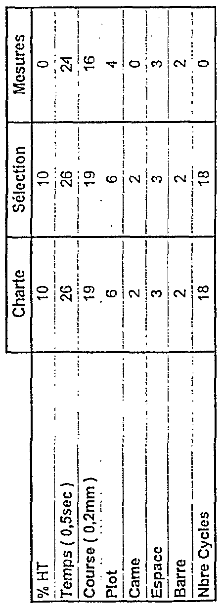
- the device comprises at least one display area of a graph (X, Y), an area where the basic data of the products to be welded are shown for a new welding sequence, after automatic introduction or by said operator, and a diagnostic zone, comprising values of predetermined welding parameters, the same parameters selected by the operator and the same parameters actually measured.
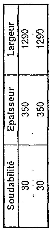
- the basic data of the products to be welded are, for the head and tail of the strip, the weldability, the thickness, the width and the section of the sheets to be welded.
- the predetermined welding parameters are selected from the group comprising the high voltage percentage, the welding time, the forging stroke, the pad used of the transformer, the cam or convexity of the displacement curve, the final space, space bar and number of forging current cycles.
- the device of the invention comprises a display area indicating the qualitative status of the weld. If the quality of the weld is insufficient, the device is provided with a display area indicating the cause.
- the graphs (X, Y) include instantaneous values, absolute or differential, measured or calculated, chosen from the group consisting of voltages, currents, dissipated energies, energy yields relating to welding and jaw displacements, the measured values being acquired at different points in the welder.
- Statistics relating to a large number of welds already carried out are displayed in diagrams, for example of the sector type ("pie chart"), histogram or Pareto.
- the present invention also aims to provide an electric end welder by direct sparking, on which is implemented the method described above.
- the electric end welder by direct sparking comprises an electronic data display device according to the invention.
- Figure 1 shows a schematic view in vertical section of the direct spark butt welder according to the invention, with indication of the circuit diagram, including the electrical sensors.
- FIG. 2 shows a schematic top view of the welder according to the invention, with an indication of a hydraulic diagram, including the pressure and position sensors.
- Figure 2 shows in particular the obliquity of the movable jaw at a given place of its movement.
- FIG 3 shows the electrical diagram according to a particular embodiment of the invention, including the current sensors, delivering a signal related to the instantaneous value of the measured current.
- Figure 4. a shows an example of variation of the voltage and the secondary current as a function of time, corresponding to an acquisition frequency of 2000 hertz measurement, for a sinusoidal alternating voltage with a frequency of 50 hertz supplying the primary of the welding transformer (s).
- Figure 4.b shows an example of calculation of variation of the energy supplied by the secondary as a function of time, corresponding to an acquisition frequency of the secondary voltage and current measurements of 2000 hertz, for an alternating voltage sinusoidal frequency 50 hertz feeding the primary of the welding transformer (s).
- FIG. 5 a represents an example of a diagnostic screen that can be displayed after a weld has been made, representing the displacement over time of the movable jaw of FIG. 2 in two different places as well as the differential displacement.
- Figure 5.b shows an example of a "mechanical" diagnostic screen that can be displayed after a weld has been made, showing the obliquity of the movable jaw as a function of its displacement during the welding process.
- FIG. 6 shows an example of a diagnostic screen that can be displayed before and after carrying out a weld, and makes it possible to test the diagnosis on change of basic data without starting the weld again.
- Figure 7 shows an example of diagnostic screen displayed after completion of a weld, in the case of a weld to be checked.
- Figure 8 shows an example of diagnostic screen identical to that of Figure 7 displayed after completion of a weld, but for a qualitatively good weld.
- Figure 9. a shows an example of calculation of variation of the energy supplied by the secondary in function of time during the complete elaboration of a weld in a faultless case.
- Figure 9.b shows an example of calculation of variation of the energy supplied by the secondary as a function of time during the complete development of a weld. In the case shown, a fault corresponding to a small variation in energy in the first half of the total time is diagnosed.
- Figure 9.c shows an example of calculation of variation of the energy supplied by the secondary according to the space traveled, during the complete development of a weld. This allows the system to diagnose faults regardless of the type of regulation of the movement of the movable table during the complete development of a weld.
- Figures 10.a and 10.b are obtained on a development station from the summary files generated after each weld and the content of which is given in table 3.
- the statistics are displayed in the form of a pie chart or
- the primary circuit consists of a primary winding 11 supplied with sinusoidal alternating current (50 or 60 Hz) by the network via terminals C, D. It is provided with at least one switch 20 and a circuit breaker 15.
- the secondary electrical circuit consists of the secondary winding 12, possible supply cables leaving therefrom, connection points A and B, stacks 22,14,13,8,7,21, 23, lower jaws 3.4, lower jaws 5.6, product 1.2 and its faces to be welded proper.
- the secondary current path is: connection point B, 22, the shunt 14, 13, 8, 4 lower, 6 lower, 2, 1, 5 lower, 3 lower, 7, 21, 23, connection point A.
- Voltage measurements 19, 16, 18 are carried out respectively at the terminals of the primary and secondary of the transformer as well as between the jaws 5, 6 of the lower jaws.
- Sensors' current 24,17 respectively installed in the primary and secondary circuits measure the corresponding currents.
- the installation comprises a single transformer with a primary and a secondary.
- the actual installation comprises, where appropriate, several transformers, each of these comprising one or more primary and / or secondary.
- the clamping of the parts 1.2 between jaws 5.6 must be sufficient to ensure good conduction of the welding current between the parts and these jaws, thanks to a low contact resistance, and to prevent any sliding. pieces between jaws when a pushing force is applied to them.
- the left clamping device 3 is fixed on a fixed table 7 secured to the frame of the machine while the right clamping device 4 is fixed on a movable table 8 which moves parallel to the axis 9 of movement of the parts welding.
- FIG. 2 gives a description of a mechanical and hydraulic diagram of a welder, in a particular embodiment, without limitation as regards the scope of the invention.
- the movable jaw 4 is actuated towards the fixed jaw 3 by means of hydraulic jacks 281.
- the hydraulic control circuit 27 of these jacks comprises a servo-valve 273, a forging solenoid valve 272, hydraulic accumulators 271 as well as a sensor for pressure 274, delivering an electrical signal related to the operating pressure.
- An additional differential pressure sensor 28 is installed on the jacks 281.
- Two linear sensors 26 provide an electrical signal, related to the distance between their points of attachment to the jaws. These sensors measure the distance between the jaws as well as the wobbling of the movable jaw.
- sparking welding the following operations are carried out successively: clamping of the parts to be welded 1,2 (Fig. 1) between the jaws 5,6 of the jaws 3,4. At this time, the ends to be assembled are not in contact or are in imperfect contact without pressure; - energizing the transformer and, therefore, the parts to be welded; slow movement of the movable table 8 and sparking phenomenon when the faces to be welded touch under low pressure; delivery or forging after a certain displacement.
- the movable table 8 being in motion, the faces to be welded parts come into contact under low pressure.
- the secondary electrical circuit is then closed by these few contact points where the current density is very high. There follows an intense heat release at these points which rapidly melt. This phenomenon is characterized by the projection of particles or "sparks", hence the name spark. It continues throughout the duration of the advance of the movable table which permanently maintains contact between the parts as the material is expelled.
- the ends to be assembled have reached the welding temperature and are applied strongly against each other by means of a rapid movement of the movable table.
- the welding current is maintained, totally or partially cut or sometimes extended beyond the end of mechanical forging.
- the clamping jaws are released and the welded part can be moved.
- the switch (s) 20 (Fig. 1) present in the primary circuit of the transformer (s) can (can) be replaced by electronic thyristor switches 30 ( Fig. 3), with adjustable ignition angle.
- the position of the various current and voltage sensors is indicated in FIG. 3, by way of example, for a particular alternative embodiment comprising two transformers 31, 32 connected to the jaws and to the jaws by the stacks 401
- In the circuit primary at least one measurement of total voltage 33 (U p ) and one measurement of total current 34 (I p ) are carried out.
- a voltage measurement is made 35,36- (U s ⁇ , U s2 ) at each secondary winding as well as between the jaws 39 (U m ).
- the currents 37.38 (I s ⁇ , I s2 ) corresponding to each secondary winding are also measured.
- the dynamic diagnosis of decision support in "real time” for electric butt welder by direct sparking and for its welds 40 is in particular characterized by the fact that one analyzes and that we value relevant electrical quantities 33,34,35,36,37,38,39 (Fig.3), not only at the primary of the transformer of the welder but also at the secondary of this one and in the vicinity of jaws 5 and 6
- FIG. 4. a gives an example of measurement of secondary current and voltage as a function of time when the measurement acquisition frequency is 2000 hertz and for a sinusoidal alternating voltage of frequency 50 hertz supplying the primary of the (or welding transformer (s).
- the duration corresponding to the fixed frequency of acquisition of the measurements is symbolized by ⁇ t (s), or even ⁇ t.
- the energy E (J) supplied for a determined period of time is calculated (Fig. 4.b).
- the determined duration is obviously an integer multiple of ⁇ t and for each time interval ⁇ t corresponds an acquisition instantaneous in voltage and current. Under these conditions, E (J) represents the result of the calculation of the sum of the instantaneous current and voltage products by ⁇ t.
- Figure 9 there is shown the variation of the calculated energy 90.94 supplied by the secondary respectively as a function of time (Fig. 9.
- the overlap is characterized by an overlap partial or total of the products to be welded before forging and by a lesser and different absorption of energy compared to correct sparking before forging.
- Knowledge of the energy as a function of displacement 94 (Fig. 9. C) as close as possible to the weld allows relevant diagnoses based on numerical analyzes characterizing this curve. In fact, the quantity of material burned during sparking should be proportional to the displacement in the absence of losses. It is also possible, for determined durations, to calculate the primary / secondary (E s / E p ), secondary / jaw (E m / E s ), primary / jaw (E m / E p ), jaw energy yields. / material (E mat / E m ).
- the material energy, in sparking, is the calorific energy necessary for the increase in temperature and for the fusion of matter. It depends on the nature of the product, its geometry, etc., and can be calculated. This makes it possible, during the diagnosis of the welds produced and of the welder according to the present invention, to know the abnormal energy losses in the various energy transfers from the primary of the welding transformer (s) to the vicinity of the welding. We can therefore diagnose in a relevant way, for example, an abnormally resistant passage of the secondary current between the stacks 22,14,13,8,7,21,23 (Fig.l), or an imbalance of energy flow between two welding transformers supplying a secondary welding circuit (Fig. 9. a).
- the analysis is not limited to electrical signals but also includes the analysis of the displacement of the movable jaw, measured at several places 41,42 (Fig. 5. a), as well as the differential displacement 43 (Fig. 5.a).
- the calculated deviations 292.293 (Fig. 2) are displayed in 44.45 (Fig. 5.b). These differences represent the difference, at two determined points, between the position of the real axis and that of the theoretical axis.
- a mechanical diagnosis will be established on the basis of the preceding measurements and calculations. A drift monitoring of the above measurements is also carried out. We can thus diagnose mechanical problems: obliquity of the movable jaw, swaying of the jaw, mechanical stresses, etc. These measurements will serve as the basis for the development of a computer diagnostic screen, accessible to the operator after each weld has been completed.
- the control screen includes, for example, push buttons accessible to the operator, directly or via a mouse. It can for example be a touch screen. Electrical and mechanical analyzes, by their nature complementary, bring to the diagnosis an appreciable degree of reliability, while the particularities of some of them enrich the choice of the relevant criteria characterizing the reliability of the weld.
- an unbalanced spark energy distribution which can be calculated from electrical measurements in the secondary circuits of the welding transformer (Fig. 4.b), is often followed by deficit forging, the latter being quantified from the measurements provided by displacement sensors 26 (Fig. 2) of the movable jaw.
- the quantification of bonding during the spark-out period is obtained from a search for a local maximum among instantaneous measurements of the secondary current for successive durations equal to the cyclic period of the voltage supplying the primary. We count the number of times these current maxima exceed a percentage threshold
- real time used in the present description should be understood as corresponding to a duration or period comprising at least the duration necessary for the development of a weld and not exceeding, for example, not more than five seconds said duration. It was mentioned previously that the result of a diagnosis will be known after the execution of the weld and presented immediately in user friendly form before the weld leaves the welding station in end. For example, in the case of a bonding defect, the text displayed at 79 or 80 (Fig. 7) is "Significant bonding before forging", the text displayed at 68 (Fig. 7) is "Welding to be checked” and box 74 changes to red.
- the control of the initial, intermediate and final positions of the movable jaw, the forged lengths, pressures , hydraulics is carried out absolutely.
- the control of the intermediate positions and the forged lengths is influenced by an encoding error or by an erroneous automatic sending of the basic data of the products to be welded: thickness, width, section to be welded and weldability of each product.
- the operator can test immediately after welding a diagnosis from possibly more relevant data and immediately benefit from the result without starting the welding again.
- FIG. 6 gives an example of a diagnostic screen that can be displayed before and after making a weld.
- the diagnosis can therefore be tested by changing the basic data (weldability 62, thickness 63, width 64 and section to be welded 65) without having to start welding again.
- the operator can modify said basic data for each new sequence 51, for the tape head (52) and the tape tail (53). He can then return to the screen in figure 7 or 8, called "process screen", by pressing button 50.
- the diagnosis is displayed in 78,74 (Fig. 7 or 8) for the new basic data entered and their parameters, in the form of a text label (78) and an indicator (74) which may be green
- the screen of FIG. 6 also allows the operator to modify before welding the automatically proposed values 47 ("10", “26”, “19”, etc.) in the part intermediate, called parameter selection 48, by means of the double arrow keys 99 ( ⁇ and ⁇ ). In this case, the diagnosis will be made from these modified parameters and no longer from the values of the welding parameters 54,55,56,57,58,59,60,61 proposed in the first line 47 ("10” , "26", "19”, etc.).
- the welding parameters well known to those skilled in the art, are respectively the high voltage percentage 54, the welding time 55, the forging stroke 56, plot 57
- the analyzes of the collages (and micro-bondings) and of the distribution of the unbalanced sparking energy are carried out in a relative manner, thus avoiding being influenced by an encoding error or by an erroneous automatic sending of the data.
- of the products to be welded thickness, width, section to be welded and weldability of each product).
- Process ( Figure 7 or Figure 8) is presented, on request or automatically.
- This screen is basically divided into three parts.
- the lower part shows, as in FIG. 6, the characteristics of the sequence numbered 51, with the basic data 62,63,64,65.
- the intermediate zone of the screen there are also, as in FIG. 6, the 'values of the parameters of the process 54,55,56,57,58,59,60,61 (Fig.
- the diagnostic screen of Figure 8 is identical to that of Figure 7 (bonding), but for a qualitatively good weld.
- Status 68 is "Soudure Ok". There is no longer any mention in 78.
- the diagnosis is based in particular on the analysis of sensor signals which are not used for the regulation of the welding machine. The diagnosis is therefore only more relevant. The analysis of the signals does not stop at a diagnosis of the weld; it also makes it possible to diagnose the electromechanical state of the tool.
- welding time if this choice is existing value of the current or of the primary and / or secondary energies if these choices exist; forging race; value of the overhangs; - choice of secondary voltage if this choice exists; choice of the displacement curve and its convexity if this choice exists; high voltage time compared to low voltage during sparking if this choice exists; number of tension cycles during which the tension is maintained after the start of forging; the ignition angles of the thyristors controlled in the different welding phases; - the spark stroke if any, etc.
- a file summarizing the analysis of the weld is also produced by the diagnostic system and archived after each weld (see example in Table 3).
- An archiving of the data of each weld is also carried out and allows the reconstitution of the "diagnostic screens" which were previously made available to the welders and this on computer equipment of the "development station” type. This archiving allows us in addition to make an in-depth study of each weld and therefore to progress in the relevance of the diagnoses made.
- On said development station statistics are made on a large number of welds carried out and new rules relating to butt welding operations are developed, more particularly for steels known to be difficult to weld.
- a summary screen is made available to view these statistics with different types of diagrams such as, for example, pie chart "pie chart” (Fig. 10. a), histogram
- the method according to this invention is very useful because it allows them to be archived and used to calibrate in particular the position sensors necessary for diagnosis. We can therefore analyze the influence of the different adjustment parameters on the quality of the weld produced. Monitoring of wearing parts such as jaws, etc., and mechanical interventions is also carried out (Table 1). Thus, the screen represented by table 1 is in particular one of the "diagnostic screens" accessible to the welder operator. Finally, the device makes it possible to memorize all the interventions carried out on the machine and to take them into account in order to carry out an analysis of the drifts between two interviews (Table 1).
Landscapes
- Engineering & Computer Science (AREA)
- Mechanical Engineering (AREA)
- Resistance Welding (AREA)
- Arc Welding Control (AREA)
- Lining Or Joining Of Plastics Or The Like (AREA)
- Investigating Strength Of Materials By Application Of Mechanical Stress (AREA)
Abstract
Description


Claims
Priority Applications (6)
| Application Number | Priority Date | Filing Date | Title |
|---|---|---|---|
| EP01971530A EP1320439A2 (fr) | 2000-09-26 | 2001-09-25 | Procede de diagnostic dynamique et d'aide a la decision en temps reel pour une soudeuse electrique en bout par etincelage direct et ses soudures |
| BR0114500-2A BR0114500A (pt) | 2000-09-26 | 2001-09-25 | Processo para diagnóstico din‰mico em tempo real e assistência de decisão para uma máquina de soldar de topo por faìsca elétrica direta e suas costuras soldadas |
| CA002420500A CA2420500A1 (fr) | 2000-09-26 | 2001-09-25 | Procede de diagnostic dynamique et d'aide a la decision en temps reel pour une soudeuse electrique en bout par etincelage direct et ses soudures |
| JP2002530255A JP2004508945A (ja) | 2000-09-26 | 2001-09-25 | 電気ダイレクト・スパーク突合せ溶接機及びその溶接シームのリアルタイム動的診断及び決定補助プロセス |
| AU2001291528A AU2001291528A1 (en) | 2000-09-26 | 2001-09-25 | Method for real time dynamic diagnosis and decision assistance, for an electric direct spark butt electric welder and its weld seams |
| US10/344,693 US20040094516A1 (en) | 2000-09-26 | 2001-09-25 | Method for real time dynamic diagnosis and decision assistance, for an electric direct spark butt electric welder and its weld seams |
Applications Claiming Priority (2)
| Application Number | Priority Date | Filing Date | Title |
|---|---|---|---|
| EP00870217.7 | 2000-09-26 | ||
| EP00870217A EP1193020A1 (fr) | 2000-09-26 | 2000-09-26 | Procédé de diagnostic dynamique et d'aide à la décision en temps réel pour une soudeuse électrique en bout par étincelage direct et ses soudures |
Publications (2)
| Publication Number | Publication Date |
|---|---|
| WO2002026436A2 true WO2002026436A2 (fr) | 2002-04-04 |
| WO2002026436A3 WO2002026436A3 (fr) | 2002-12-12 |
Family
ID=8175817
Family Applications (1)
| Application Number | Title | Priority Date | Filing Date |
|---|---|---|---|
| PCT/BE2001/000166 Ceased WO2002026436A2 (fr) | 2000-09-26 | 2001-09-25 | Procede de diagnostic dynamique et d'aide a la decision en temps reel pour une soudeuse electrique en bout par etincelage direct et ses soudures |
Country Status (8)
| Country | Link |
|---|---|
| US (1) | US20040094516A1 (fr) |
| EP (2) | EP1193020A1 (fr) |
| JP (1) | JP2004508945A (fr) |
| CN (1) | CN1462218A (fr) |
| AU (1) | AU2001291528A1 (fr) |
| BR (1) | BR0114500A (fr) |
| CA (1) | CA2420500A1 (fr) |
| WO (1) | WO2002026436A2 (fr) |
Families Citing this family (10)
| Publication number | Priority date | Publication date | Assignee | Title |
|---|---|---|---|---|
| ITMI20030589A1 (it) * | 2003-03-25 | 2004-09-26 | Danieli Off Mecc | Sistema e metodo per il controllo in linea di una macchina |
| CA2837436A1 (fr) * | 2011-05-26 | 2012-11-29 | Thermal Dynamics Corporation | Systeme pour generer une soudure et procede pour commander un appareil de soudage avec modification de tension et de vitesse de fil sur la base d'une puissance de sortie de soudure commandee |
| US9314878B2 (en) * | 2013-09-12 | 2016-04-19 | Ford Global Technologies, Llc | Non-destructive aluminum weld quality estimator |
| CN103551709B (zh) * | 2013-11-16 | 2015-04-22 | 沈阳工业大学 | 一种a-tig焊焊缝成型的检测装置及方法 |
| US10537960B2 (en) * | 2014-03-26 | 2020-01-21 | Nv Bekaert Sa | Weld between steel cord ends, method and apparatus to implement such weld |
| CN106513963B (zh) * | 2016-12-09 | 2018-11-23 | 珠海启世机械设备股份有限公司 | 一种闪光焊的方法和系统 |
| WO2021019105A1 (fr) * | 2019-07-30 | 2021-02-04 | Lortek, S.Coop | Dispositif d'évaluation d'équipements de soudure fbw et procédé d'évaluation associé |
| CN116352305B (zh) * | 2023-03-09 | 2026-02-13 | 江苏科技大学 | 一种基于焊接过程特征的闪光对焊质量评估方法 |
| CN118635732B (zh) * | 2024-08-14 | 2024-11-19 | 恩督重工(南通)有限公司 | 一种管道焊接路径规划方法及系统 |
| CN121423788B (zh) * | 2025-12-29 | 2026-04-14 | 山东奥冠自动化设备有限公司 | 一种无光直流对焊机 |
Family Cites Families (6)
| Publication number | Priority date | Publication date | Assignee | Title |
|---|---|---|---|---|
| US4376242A (en) * | 1976-01-30 | 1983-03-08 | Republic Steel Corporation | Flash welding apparatus and method |
| AT386370B (de) * | 1986-12-01 | 1988-08-10 | Inst Elektroswarki Patona | Verfahren zum widerstands-abbrennstumpfschweissen |
| US5302799A (en) * | 1991-12-09 | 1994-04-12 | Applied Research, Inc. | Weld analysis and control system |
| US5367138A (en) * | 1993-06-28 | 1994-11-22 | Automation International Incorporated | Welding assurance control techniques |
| US5837968A (en) * | 1996-07-15 | 1998-11-17 | Creative Pathways, Inc. | Computer-controlled modular power supply for precision welding |
| US6002104A (en) * | 1998-04-17 | 1999-12-14 | Lincoln Global, Inc. | Electric arc welder and controller therefor |
-
2000
- 2000-09-26 EP EP00870217A patent/EP1193020A1/fr not_active Withdrawn
-
2001
- 2001-09-25 CN CN01816091A patent/CN1462218A/zh active Pending
- 2001-09-25 BR BR0114500-2A patent/BR0114500A/pt not_active IP Right Cessation
- 2001-09-25 CA CA002420500A patent/CA2420500A1/fr not_active Abandoned
- 2001-09-25 JP JP2002530255A patent/JP2004508945A/ja active Pending
- 2001-09-25 EP EP01971530A patent/EP1320439A2/fr not_active Withdrawn
- 2001-09-25 US US10/344,693 patent/US20040094516A1/en not_active Abandoned
- 2001-09-25 AU AU2001291528A patent/AU2001291528A1/en not_active Abandoned
- 2001-09-25 WO PCT/BE2001/000166 patent/WO2002026436A2/fr not_active Ceased
Also Published As
| Publication number | Publication date |
|---|---|
| CA2420500A1 (fr) | 2002-04-04 |
| CN1462218A (zh) | 2003-12-17 |
| EP1193020A1 (fr) | 2002-04-03 |
| EP1320439A2 (fr) | 2003-06-25 |
| WO2002026436A3 (fr) | 2002-12-12 |
| JP2004508945A (ja) | 2004-03-25 |
| BR0114500A (pt) | 2003-10-14 |
| US20040094516A1 (en) | 2004-05-20 |
| AU2001291528A1 (en) | 2002-04-08 |
Similar Documents
| Publication | Publication Date | Title |
|---|---|---|
| EP1320439A2 (fr) | Procede de diagnostic dynamique et d'aide a la decision en temps reel pour une soudeuse electrique en bout par etincelage direct et ses soudures | |
| EP3176537B1 (fr) | Système d'inspection automatisée de soudures en cours de production | |
| US6236017B1 (en) | Method and apparatus for assessing weld quality | |
| EP1206992B1 (fr) | Appareil et méthode pour la surveillance d'un appareil de soudage a l'arc | |
| EP1252962A2 (fr) | Appareil d'évaluation de stabilité d'un processus de soudage à l'arc pulsé | |
| EP1534458B1 (fr) | Procede de controle de qualite de points de soudage | |
| CH682600A5 (fr) | Procédé de contrôle de qualité de l'impression et du découpage dans une installation de production d'emballages. | |
| Yu et al. | Arc spectral processing technique with its application to wire feed monitoring in Al–Mg alloy pulsed gas tungsten arc welding | |
| US20240383072A1 (en) | Computer-implemented monitoring of a welding operation | |
| CN111015006B (zh) | 基于光谱信息的激光电弧复合焊接质量在线监测方法 | |
| JP2018113198A (ja) | 検査装置及び巻回装置 | |
| EP2769303A1 (fr) | Procede de detection preventive d'une panne d'un appareil, programme d'ordinateur, installation et module de détection préventive d'une panne d'un appareil | |
| CA2601865A1 (fr) | Procede de detection automatique de l'usure d'une electrode de soudage | |
| US20080237197A1 (en) | System and method for welding and real time monitoring of seam welded parts | |
| Din et al. | Multi-model feature aggregation for classification of laser welding images with vision transformer | |
| EP1776203A1 (fr) | Procede de supervision d'un procede de soudage par resistance et dispositif pour la mise en oeuvre de ce procede | |
| EP2560785B1 (fr) | Procede et dispositif de controle d'un cycle thermique d'une soudure par raboutage d'extremites de bandes | |
| EP4732362A1 (fr) | Procédé et système de détection de défaut d'électrode | |
| JP4998709B2 (ja) | 溶接合否判定装置及び溶接合否判定方法 | |
| KR101394994B1 (ko) | 용접 용적이행 모드 규명장치 및 규명 방법 | |
| JP3709807B2 (ja) | 溶接状態判定方法、およびその装置 | |
| JPH11123547A (ja) | アーク溶接定常部の溶接安定性判定方法及び安定性判定装 置 | |
| JP4657880B2 (ja) | 端子圧着不良検出装置の圧着不良判定データ作成方法および圧着不良判定データ検査方法 | |
| DE202013011975U1 (de) | Vorrichtung zur Herstellung von Stahlfässern | |
| JP2000301349A (ja) | 抵抗溶接検査装置 |
Legal Events
| Date | Code | Title | Description |
|---|---|---|---|
| AK | Designated states |
Kind code of ref document: A2 Designated state(s): AE AG AL AM AT AU AZ BA BB BG BR BY BZ CA CH CN CO CR CU CZ DE DK DM DZ EC EE ES FI GB GD GE GH GM HR HU ID IL IN IS JP KE KG KP KR KZ LC LK LR LS LT LU LV MA MD MG MK MN MW MX MZ NO NZ PH PL PT RO RU SD SE SG SI SK SL TJ TM TR TT TZ UA UG US UZ VN YU ZA ZW |
|
| AL | Designated countries for regional patents |
Kind code of ref document: A2 Designated state(s): GH GM KE LS MW MZ SD SL SZ TZ UG ZW AM AZ BY KG KZ MD RU TJ TM AT BE CH CY DE DK ES FI FR GB GR IE IT LU MC NL PT SE TR BF BJ CF CG CI CM GA GN GQ GW ML MR NE SN TD TG |
|
| DFPE | Request for preliminary examination filed prior to expiration of 19th month from priority date (pct application filed before 20040101) | ||
| 121 | Ep: the epo has been informed by wipo that ep was designated in this application | ||
| AK | Designated states |
Kind code of ref document: A3 Designated state(s): AE AG AL AM AT AU AZ BA BB BG BR BY BZ CA CH CN CO CR CU CZ DE DK DM DZ EC EE ES FI GB GD GE GH GM HR HU ID IL IN IS JP KE KG KP KR KZ LC LK LR LS LT LU LV MA MD MG MK MN MW MX MZ NO NZ PH PL PT RO RU SD SE SG SI SK SL TJ TM TR TT TZ UA UG US UZ VN YU ZA ZW |
|
| AL | Designated countries for regional patents |
Kind code of ref document: A3 Designated state(s): GH GM KE LS MW MZ SD SL SZ TZ UG ZW AM AZ BY KG KZ MD RU TJ TM AT BE CH CY DE DK ES FI FR GB GR IE IT LU MC NL PT SE TR BF BJ CF CG CI CM GA GN GQ GW ML MR NE SN TD TG |
|
| WWE | Wipo information: entry into national phase |
Ref document number: 2001971530 Country of ref document: EP |
|
| WWE | Wipo information: entry into national phase |
Ref document number: 2420500 Country of ref document: CA |
|
| WWE | Wipo information: entry into national phase |
Ref document number: 018160913 Country of ref document: CN |
|
| WWE | Wipo information: entry into national phase |
Ref document number: 2002530255 Country of ref document: JP |
|
| WWP | Wipo information: published in national office |
Ref document number: 2001971530 Country of ref document: EP |
|
| REG | Reference to national code |
Ref country code: DE Ref legal event code: 8642 |
|
| WWE | Wipo information: entry into national phase |
Ref document number: 10344693 Country of ref document: US |
|
| WWW | Wipo information: withdrawn in national office |
Ref document number: 2001971530 Country of ref document: EP |