WO2003076823A1 - Oscillation adjuster and oscillation adjusting method - Google Patents
Oscillation adjuster and oscillation adjusting method Download PDFInfo
- Publication number
- WO2003076823A1 WO2003076823A1 PCT/JP2003/002931 JP0302931W WO03076823A1 WO 2003076823 A1 WO2003076823 A1 WO 2003076823A1 JP 0302931 W JP0302931 W JP 0302931W WO 03076823 A1 WO03076823 A1 WO 03076823A1
- Authority
- WO
- WIPO (PCT)
- Prior art keywords
- output
- rotation
- unit
- vibration
- driving force
- Prior art date
- Legal status (The legal status is an assumption and is not a legal conclusion. Google has not performed a legal analysis and makes no representation as to the accuracy of the status listed.)
- Ceased
Links
Classifications
-
- F—MECHANICAL ENGINEERING; LIGHTING; HEATING; WEAPONS; BLASTING
- F16—ENGINEERING ELEMENTS AND UNITS; GENERAL MEASURES FOR PRODUCING AND MAINTAINING EFFECTIVE FUNCTIONING OF MACHINES OR INSTALLATIONS; THERMAL INSULATION IN GENERAL
- F16F—SPRINGS; SHOCK-ABSORBERS; MEANS FOR DAMPING VIBRATION
- F16F15/00—Suppression of vibrations in systems; Means or arrangements for avoiding or reducing out-of-balance forces, e.g. due to motion
- F16F15/02—Suppression of vibrations of non-rotating, e.g. reciprocating systems; Suppression of vibrations of rotating systems by use of members not moving with the rotating systems
-
- G—PHYSICS
- G05—CONTROLLING; REGULATING
- G05D—SYSTEMS FOR CONTROLLING OR REGULATING NON-ELECTRIC VARIABLES
- G05D19/00—Control of mechanical oscillations, e.g. of amplitude, of frequency, of phase
- G05D19/02—Control of mechanical oscillations, e.g. of amplitude, of frequency, of phase characterised by the use of electric means
-
- F—MECHANICAL ENGINEERING; LIGHTING; HEATING; WEAPONS; BLASTING
- F02—COMBUSTION ENGINES; HOT-GAS OR COMBUSTION-PRODUCT ENGINE PLANTS
- F02P—IGNITION, OTHER THAN COMPRESSION IGNITION, FOR INTERNAL-COMBUSTION ENGINES; TESTING OF IGNITION TIMING IN COMPRESSION-IGNITION ENGINES
- F02P5/00—Advancing or retarding ignition; Control therefor
- F02P5/04—Advancing or retarding ignition; Control therefor automatically, as a function of the working conditions of the engine or vehicle or of the atmospheric conditions
- F02P5/145—Advancing or retarding ignition; Control therefor automatically, as a function of the working conditions of the engine or vehicle or of the atmospheric conditions using electrical means
- F02P5/15—Digital data processing
- F02P5/1502—Digital data processing using one central computing unit
- F02P5/1514—Digital data processing using one central computing unit with means for optimising the use of registers or of memories, e.g. interpolation
Definitions
- the present invention relates to a vibration adjusting device and a vibration adjusting method for reducing vibration in a driving direction of a driving target driven by a driving force generating unit.
- the in-phase vibration of the entire device has a different vibration mode from that of the rotational motion, it cannot be removed by controlling the torque of the motor all the time, and eccentricity and dynamic imbalance are the methods of suppressing in-phase vibration. It is common to increase the mechanical accuracy of the rotating body so that it does not become a source. However, the method of increasing the mechanical accuracy requires time for processing and mounting of the rotating body, resulting in an increase in the cost of the apparatus.
- the present invention has been made based on such circumstances, and its object is to provide a rotating body.
- a vibration adjusting device includes: a driving force generating unit that drives a driven object; a rotating body that is rotated by the driving force of the driving force generating unit; Driving force commanding means for commanding thrust or torque to be performed, rotation detecting means for detecting the rotational movement of the rotating body, and a rotation angle for outputting a rotation angle of the rotating body based on an output of the rotation detecting means.
- a conversion unit a trigonometric function operation unit that calculates a sine value or a cosine value of an angle represented by a linear function of the rotation angle output from the rotation angle detection unit;
- a gain adjustment unit that multiplies the gain of (a), (b), and a driving force command correction unit that corrects an output of the driving force command unit based on a calculation result of the rotation calculation unit.
- the rotation calculation means may further include a phase adjustment unit that outputs a predetermined adjustment phase value as a linear function intercept of the output of the rotation angle conversion unit.
- the angle expressed as a linear function of the rotation angle is an angle obtained by adding the adjustment phase value to the rotation angle, and the trigonometric function operation unit calculates the adjustment phase value as the rotation angle.
- the sine value or cosine value of the obtained angle is calculated.
- the rotation calculating means further outputs an angular velocity converting section for outputting an angular velocity of the rotating body based on an output of the rotation detecting means; and an output from the angular velocity converting section to an output of the trigonometric function calculating section or the gain adjusting section. And an angular velocity multiplying unit that multiplies the square of the calculated angular velocity by a square.
- the rotation calculation means further includes: an angular acceleration conversion unit configured to output an angular acceleration of the rotating body based on an output of the rotation detection means; and an angular acceleration conversion unit configured to output the trigonometric function calculation unit or the gain adjustment unit. And an angular acceleration multiplying unit that multiplies the output of the above.
- the driving force command correction means includes an output of the driving force command means and a gain adjustment unit.
- An adder for calculating the sum of outputs may be provided.
- the driving force command correction means may include an adder for calculating a sum of an output of the driving force command means and an output of the angular velocity multiplying unit.
- the driving force command correction means may include an adder that calculates a sum of the output of the angular acceleration multiplication unit and the output of the angular velocity multiplication unit.
- the driving force command correcting means may include an adder for calculating a sum of an output of the driving force command means, an output of the angular velocity multiplying unit, and an output of the gain adjusting unit.
- the driving force command correction means may correct the output of the driving force command means based on the eccentricity compensation amount FCD.
- the driving force command correction means may correct the output of the driving force command means based on the dynamic imbalance compensation amount FCD.
- the driving force command correcting means may correct the output of the previous SL driving force command unit based on the eccentricity Cain balance compensation amount F CF.
- the rotation calculation means may include a gain switching means for setting a gain of the gain adjustment unit by switching a plurality of predetermined values according to an operation state of the drive target.
- the rotation calculation means may include phase switching means for setting the phase of the phase adjustment unit by switching a plurality of predetermined values according to an operation state of the drive target.
- the rotation calculation means may include a phase setting unit that sets a phase of the phase adjustment unit according to a rotation direction of the rotator.
- the rotation angle conversion unit may include an integrator that integrates an output of the angular velocity conversion unit.
- the vibration adjusting device may further include a vibration detecting unit configured to detect a vibration of the driving target in a driving direction.
- the vibration detecting means may include an acceleration detecting means for detecting the acceleration of the drive target.
- the rotation detecting means may have a resolver.
- the rotation detecting means may include a generator. Further, the rotation detecting means may include an encoder.
- C The rotating body may be a rotor of an electric motor.
- the rotating body may be a main sheep of an elevator system. Further, the rotating body may be a compensive of an elevator system.
- the drive target may be a car of an elevator system.
- the present invention provides a driving force generating means for driving a driving target, a rotating body which is rotated by the driving force of the driving force generating means, and a driving force for instructing a thrust or a torque to be generated by the driving force generating means.
- a driving force generating means for driving a driving target, a rotating body which is rotated by the driving force of the driving force generating means, and a driving force for instructing a thrust or a torque to be generated by the driving force generating means.
- a commanding means and a method for adjusting a vibration generated in the driven object by correcting a command output of the driving force commanding means using a predetermined compensation value.
- the method includes: a rotation detecting step including a step of obtaining a rotation angle of the rotating body; and an angle that can be expressed as a linear function of the rotation angle.
- a determining step including a step of determining the gain so as to minimize the gain.
- an angle obtained by adding a predetermined adjustment phase value to the rotation angle may be used as the angle that can be expressed as a linear function of the rotation angle. Determining the adjustment phase value such that the amplitude of the predetermined vibration component is minimized.
- the rotation detecting step further includes a step of obtaining an angular velocity of the rotating body, and in the calculating step, based on a product of the product of the sine value or cosine value and the gain, and an angular velocity of the rotating body.
- the compensation value may be calculated.
- the rotation detecting step further includes a step of obtaining an angular acceleration of the rotating body, and in the calculating step, the product of the sine value or cosine value and the gain; and an angular acceleration of the rotating body.
- the compensation value may be calculated on the basis of the product of and.
- the present invention effectively reduces vibrations generated in a driven object by using motor torque or thrust in a device that generates vibrations due to eccentricity or dynamic imbalance of a rotating body driven by a motor.
- a plurality of rotating bodies have eccentricity or dynamic imbalance individually, a plurality of the rotation calculation means are provided corresponding to the vibration components caused by each rotating body. It can be reduced effectively.
- the vibration generated in the driven object is suppressed by converting the rotational force generated by the motor as the driving force generating means into the driving force in the driving direction, but the vibration generated in the whole device includes the link mechanism in addition to the driving force generating means.
- the torque and linear drive force conversion mechanism that combines a belt, rope, or rope with a rotating body also vibrates, so it is extremely difficult to suppress vibrations due to torque.
- the exciting force F in the driving direction in which the rotating body having the dynamic imbalance is generated by the centrifugal force fc can be expressed by the following equation 5 as 6> as the rotation angle of the rotating body having dynamic imbalance, and as the phase difference between the exciting force and the rotating body rotation angle.
- the driving force command means for causing the driven object to perform a predetermined motion, for example, by calculating the angular velocity w m of a driving sieve (rotating body) connected to a motor rotor. Target angular velocity.
- Servo control is performed to match the output value of the driving force command means, that is, the torque command value ⁇ . Is output.
- the torque command value Tc is defined by the following equation 11 using the rotation angle 0 and the angular velocity ⁇ of the rotating body having the dynamic imbalance.
- the torque command value T d is calculated by the following equation 19 using the rotation angle 0 d of the eccentric rotating body. k
- the eccentric excitation force F r can be obtained by multiplying the acceleration obtained from the displacement Z d in Equation 17 by the eccentrically excited mass m d , where w d is the angular velocity of> d , and ⁇ is the angle of 0 d As the acceleration,
- T r ⁇ 0 sm (e d + ⁇ ⁇ ) + cos (d d + (f> r ))
- kr and 0 r are the gain adjustment parameters and the phase adjustment parameters, respectively.
- the driving force Fm acting on the driven object by the torque command value Tr is given by the above equation 7,
- F (s) F m0 (s) + L l k r (one ⁇ ⁇ 2 sin ( ⁇ ⁇ + ⁇ ⁇ ) + ⁇ cos (d d + t r jJjG (s) + L m d r d (one ⁇ sin (3 ⁇ 4
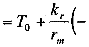
- Equation (3 1) If the angular velocity ⁇ d of the eccentric rotating body in the equation 31 is constant, the equation is (3), and the gain and phase difference of G (s) are G db and ⁇ and G, also the gain and phase difference of R (s) which it: db, as ⁇ B, the vibration component of the second term and third term of the right side of the equation 31, as the inverse Laplace transform of L _ 1, VL k rd 2 sm (e d (s) G db k rd sin (3 ⁇ 4 + ⁇ ⁇ + ⁇ 0
- FIG. 1 is a perspective view showing an overall structure of a first embodiment of a vibration adjusting device according to the present invention.
- FIG. 2 is a block diagram showing the overall configuration of the vibration adjustment device according to the first embodiment.
- FIG. 3 is a schematic diagram showing a configuration of an elevator system provided with the vibration adjustment device according to the first embodiment.
- FIG. 4 is a pattern diagram showing a relationship between an angular velocity command value and time in the first embodiment.
- FIG. 5 is a pattern diagram showing a relationship between acceleration and time according to the first embodiment.
- FIG. 6 is a pattern diagram showing a relationship between acceleration and time according to the first embodiment.
- FIG. 7 is a pattern diagram showing a relationship between acceleration and time according to the first embodiment.
- FIG. 8 is a perspective view showing the overall structure of a modification of the first embodiment.
- FIG. 9 is a perspective view showing the overall structure of another modification of the first embodiment.
- FIG. 10 is a schematic diagram showing a configuration of an elevator system provided with a vibration adjusting device according to a second embodiment of the present invention.
- FIG. 11 is a block diagram illustrating an overall configuration of a vibration adjustment device according to a second embodiment.
- FIG. 12 is a schematic diagram showing a configuration of a uniaxial positioning tape device provided with a vibration adjusting device according to a third embodiment of the present invention.
- FIG. 13 is a block diagram showing the overall configuration of the vibration adjustment device according to the third embodiment.
- FIG. 14 is a block diagram showing an overall configuration of a vibration adjusting device according to a fourth embodiment of the present invention.
- FIGS. 1 to 3 show the vibration adjusting device according to the first embodiment as a whole, and include a rotary electric motor 11 as a driving force generating means and a moving body 14 as a driving target.
- the Elebe overnight system is shown generally at 5.
- the vibration adjusting device 1 includes a rotation detecting means C1 and rotation calculating means C2, C2 '.
- the rotation detecting means C 1 in the present embodiment is attached to a rotary electric motor 11 to be detected, and a resolver 15 and a resolver 15 that output a voltage proportional to the rotation angle of the rotor rotation shaft 13 of the rotary electric motor 11.
- Rotation transmission that connects the input rotary shaft 17 directly connected to the rotor 15 (not shown) and the rotor rotary shaft 13 and transmits the rotation of the rotor rotary shaft 13 to the input rotary shaft 17 of the resolver 15 Means consist of 19.
- the rotation transmitting means 19 is provided with, for example, a universal joint and a cutter.
- the resolver 15 is composed of a rotor (not shown) provided with a winding and a stator 21 also provided with a winding, and the rotation angle of the input rotary shaft 17 from a predetermined origin is 0 to 2 ⁇ ( Each rad) is provided with a signal processing unit 23 that outputs a voltage corresponding to the rotation angle, for example, a voltage of 0 to 5 (V).
- the stator 21 of the resolver 15 is fixed on a base plate 25 by a support member 27 by a predetermined method.
- Rotary motor 11 which is a driving force generating means will be described.
- Rotary motor 11 is mounted on a base 29 and fixed by a stop 31 to be integrated with the base 29.
- the rotating motor 11 can rotate the rotor rotating shaft 13 at the center of the cylindrical bottom surface of the stator housing 33 and the stator housing 33 that incorporate the stator of the rotating motor 11 in addition to the rotor rotating shaft 13.
- Bearing 35 which is attached to the other end of the rotor rotating shaft 13 and transmits the torque of the rotating electric motor 11 to the moving body 14 to be driven via the rope 36 as a rotating body.
- a speed control device 39 for calculating a torque command value for controlling the rotation speed of the rotor rotating shaft 13 based on the output of the vibration adjustment device 1, receiving power from the three-phase AC power supply 41 and controlling the speed
- a drive device 43 is provided for generating a torque equal to the torque command value on the rotor rotating shaft 13 based on the output of the device 39.
- the output of the rotation detecting means C1 is introduced to the rotation calculating means C2, C2 '.
- the rotation calculation means C2 includes a rotation angle conversion unit 45 that converts the output of the signal processing unit 23 into a rotation angle of the rotor rotation shaft 13, and an angular velocity that converts the output to the angular speed of the rotor rotation shaft 13.
- ( ⁇ + ⁇ ) is input and a sine operation unit 55 that calculates a sine value (sin ( ⁇ + ⁇ )) of the input value, a gain adjustment unit that multiplies the output of the sine operation unit 55 by an adjustable gain 57, a multiplier 59 for squaring the output ( ⁇ ) of the angular velocity calculator 47, and the output (G in ( ⁇ + 2 )) of the gain adjuster 57 and the output of the multiplier 59
- a multiplier 61 is provided as an angular velocity multiplier for multiplying ( ⁇ 2 ).
- the phase adjustment unit 49, the adder 53, and the sine operation unit 55 constitute a trigonometric function operation unit C3 as a whole.
- the rotation calculating means C2 ′ adjusts a phase angle with respect to the output of the rotation angle conversion unit 45, s as a rotation angle conversion unit 45 ′ s as an integrator for integrating the angular velocity output from the angular velocity conversion unit 47. And an output of the adder 53, which adds the output of the phase adjuster 49 ′ (i and the output (0) of the rotation angle converter 45 s). Sine operation to calculate the sine value of the input value And a gain adjusting unit 57 'for multiplying the output (sin i ⁇ + ⁇ i)) of the sine calculating unit 55' by an adjustable gain G.
- the trigonometric function operation unit C 3 ′ includes the phase adjustment unit 49 ′, the adder 53 ′, and the sine operation unit 55 ′.
- the speed controller 39 includes an angular velocity target pattern generator 65 that outputs an angular velocity target pattern to be followed by the angular velocity of the rotor rotation shaft 13, an output of the angular velocity target pattern generator 65, and an angular velocity converter 4 7. And a torque command calculating section 67 for calculating a torque command value for causing the rotation speed of the rotor rotating shaft 13 to follow a target pattern based on the output.
- the output of the torque command calculator 67 is added together with the respective outputs of the multiplier 61 and the gain adjuster 57 'and output from the adder 68 as a composite vibration adjustment adder.
- the driving device 43 includes a converter 69 for converting the power from the three-phase AC power supply 41 into DC power, an output of the adder 68 and an output of the rotation angle converter 45's.
- An inverter 71 for supplying three-phase AC power from the DC power of the converter 69 so that the rotary motor 11 generates a torque equal to the output value of the adder 68.
- the inverter 71 is an output of the adder 68 and a sheave output by the rotation angle converter 45 3 s so that the rotary motor 11 is excited by a three-phase alternating current that generates a predetermined torque.
- the vibration adjustment device 1 In the vibration adjustment device 1, the speed control device 39, and the drive device 43, the power required for the operation of these devices is supplied from a single-phase AC power supply 77.
- arrow lines indicate signal paths
- bar lines indicate electric power paths around the rotary motor 11 and the vibration adjustment device 1.
- the elevator system 5 includes a guide rail 79 laid vertically in a predetermined manner, a moving body 14 moving vertically along the guide rail 79, and a moving body 1 moving from above.
- a sheave support means 89 for applying a damping force to the up and down movement of the sheave 87 caused by a change in the tension of the rope 85 and guiding the sheave 87 to the left and right.
- the moving body 14 has a sufficient rigidity against the tension of the ropes 36 and 85.
- the car frame 91 and the moving body 14 are arranged at the four corners of the car frame 91 and move the moving body 14 along the guide rails 79.
- a suspension 97 is provided for shutting off and supporting the car 95 with respect to the car frame 91.
- an acceleration detector 99 for detecting the vertical acceleration of the car 95 is attached to the car 95 to be driven by a predetermined method as acceleration detection means.
- the detection result of the acceleration detector 99 is introduced by a cable (not shown) into the acceleration display means 101 arranged near the rotation calculation means C2, C2, and the acceleration detection result is, for example, a time chart. Is displayed.
- the rotary electric motor 11 is attached to the machine bed 103 together with the secondary sheave 81 via the pace 29 in a predetermined manner, and constitutes the electric motor unit 104 as a whole.
- the machine bed 103 is mounted on an upper floor 107 of a building (not shown) via an anti-vibration rubber 105. It goes without saying that the secondary seeb 81 can rotate freely under the tension of the rope 36.
- the sheave support means 89 includes a bearing 109 for rotatably supporting the sheave 87, and a sheave 87 for guiding the sheave 87, which is disposed so as to sandwich the bearing 109 from both sides and moves up and down. It is composed of Bug Guide 1 1 1.
- the sheave guy The lower end of the door 1 1 1 is fixed to the lower floor 1 1 3 of a building (not shown).
- the device is in a standby state, that is, the three-phase AC power supply 41 and the single-phase AC power supply 77 are turned on, and the vibration adjustment device 1, the speed control device 39 and the driving device 43 are in operation but the angular velocity target pattern generator 6
- the rotor rotation shaft 13 maintains the state of zero angular velocity.
- zero is set in the gain adjustment units 57 and 57.
- the angular velocity target pattern generator 65 generates a trapezoidal pattern as shown in FIG.
- the current rotation output from the angular velocity converter 47 in the torque command calculator 67 A torque command value to be generated by the rotary motor 11 is calculated based on the angular velocity of the slave rotating shaft 13 and the angular velocity target value of the target pattern generator 65, and the calculation result is output to the drive unit 4 via the adder 68. Output to 3.
- the firing angle control section 75 controls the firing angle of the thyristor section 73 so that the rotary electric motor 11 generates the torque according to the command value.
- the rotating motor 11 generates the torque according to the command value.
- the sheave 37 starts rotating together with the rotor rotating shaft 13 by the torque of the rotating electric motor 11.
- the rotation of the rotor rotation shaft 13 is input to the resolver 15 via the rotation transmission means 19 and the rotation input shaft 17, and the signal processor 23 responds to the increase in the rotation angle of the rotor rotation shaft 13. And the output voltage rises.
- the output voltage of the signal processing unit 23 is converted by the rotation angle conversion unit 45 into the rotation angle of the rotor rotating shaft 13, while it is converted into the angular velocity by the angular velocity conversion unit 47 by, for example, a pseudo differentiator.
- This angular velocity is fed back to the torque command calculating section 67 again, and the rotational speed (angular velocity) of the sheave 37 follows the target value as shown in FIG.
- the tension is transmitted to the moving body 14 via the rope 36 hung on the sheave 37, and the moving body 14 also rises following the predetermined target speed pattern. In this case, the moving body 14 moves at an acceleration as shown in FIG.
- vibration occurs around the center of gravity of the motor unit 104 supported by the vibration isolating rubber 105, and a vibration component of the vibration in the driving direction of the moving body 14, that is, the vertical direction, is transmitted to the moving body 14 via the rope 36.
- the vertical vibration component of this vibration propagates to the weight part 83.
- the vibration also propagates to the ship 87 via the rope 85, and eventually, the entire elevator system 5 vertically moves.
- the output of the rotation calculating means C 2 is added to the output of the torque command calculating section 67, and the vibrating force of the above-described equation 6 for vibrating the moving body 14 is obtained.
- the output of the rotation detecting means C 1 is introduced into the rotation angle conversion unit 45, and the rotation angle (0) output from the rotation angle conversion unit 45 is added by the adder 53 to the predetermined phase angle ( is introduced to the sine arithmetic unit 55 is, the sine value (sin (theta + phi 2)).
- Equation 14 ⁇ ⁇ ⁇ ⁇ , gain k m and excitation force acting on the movable body 14 equal to the phase difference is defined by i ⁇ 6 Roh are offset vertically
- the moving body 14 rises smoothly without generating vibration.
- the velocity target pattern shown in FIG. 4 may be multiplied by ⁇ 1 and output from the angular velocity target pattern generator 65. In this case, the relations of the above equations 13 and 16 may be satisfied. Equation 14
- the output of the rotation calculating means C 2 is added to the output of the torque command calculating section 67, and the vibrating force expressed by the above equation 18 vibrates the moving body 14.
- the output ( ⁇ ) of the angular velocity conversion unit 47 is introduced into the rotation angle conversion unit 45's, and the rotation angle (0) output from the rotation angle conversion unit 45's is added to the phase adjustment unit 49 'in the adder 53'.
- the sine calculation unit 55 is added to the predetermined phase angles ⁇ , and are introduced into the sine calculation unit 55, where the sine value (sin ( ⁇ + ⁇ )) of the output value of the adder 53 is calculated.
- the output of the sine operation unit 55 is multiplied by a predetermined gain (G) in the gain adjustment unit 57, and the output of the rotation operation unit C2 'is obtained.
- the acceleration display means displays a vertical vibration of the moving body 14 larger than that in FIG. 6, for example, as shown in FIG.
- phase difference t While moving up and down the moving body 14 while increasing (decreasing) the phase difference, the phase difference t is fixed when the vertical vibration amplitude of the moving body 14 becomes minimum.
- the moving object 14 is repeatedly moved up and down while increasing (decreasing) the gain, and the gain is fixed when the vertical vibration amplitude of the moving object 14 becomes minimum.
- the gain and the phase difference i become equal to the gain k d and the phase difference ⁇ d, respectively, and the vertical vibration of the moving body 14 due to the eccentricity is canceled.
- the vibration waveform of FIG. 6 is displayed on the acceleration display means. appear.
- phase difference 2 (reduction) is allowed while repeatedly lifting of the moving body 1 4, upper and lower vibration amplitude of the moving body 1 4 fixes the phase difference 2 upon reaching the minimum.
- the vertical vibration generated in the moving body 14 due to the mechanical accuracy such as the dynamic imbalance and the eccentricity of the ship 37 is eliminated by the torque control.
- the performance required for the equipment such as the ride comfort standard defined by the acceleration of the car 95, and excellent ride comfort without relying on the rigidity and machining accuracy of the entire equipment.
- two rotation calculation means are provided in order to cope with complex vertical vibration of the moving body 14 due to dynamic imbalance and eccentricity.
- the number of means to be used is not limited at all, and a necessary number may be provided according to the number of rotating bodies having dynamic imbalance or eccentricity.
- the sheave as a rotating body has dynamic imbalance and eccentricity, but this does not limit the kind of rotating body having dynamic imbalance or eccentricity at all. It may be.
- the rotation detecting means includes a resolver
- this does not limit the configuration of the rotation detecting means at all, and various modifications are possible.
- a generator that can obtain an output voltage proportional to an increase in the angular velocity of the input shaft can be used.
- the rotation of the rotary electric motor 11 is transmitted by the rotation transmission means 19 and the rotation input shaft 17, which restricts the form of the rotation transmission means 19 and the use of the rotation input shaft 17.
- equidistant stripes 115 are provided around the end of the rotor rotation shaft 13, and the optical elements 1 17 attached to the signal processing unit 23 ′ are used.
- An optical encoder 119 serving as a rotation detecting means C for reading this, or a rotation of a rotor rotating shaft 13 via a roller 122 serving as a rotation transmitting means as shown in FIG.
- the rotation detection means C which transmits the signal to the evening encoder 123, may be used.
- the vibration adjuster 1, the speed controller 39 and the drive 43 are separately arranged.
- this does not limit the arrangement and installation location of each device, and the vibration control device is installed as a whole or divided in the speed control device or the drive device, or in the drive device. There is no problem even if a vibration adjuster and a speed controller are installed in the system.
- the rotating body is a sheave 37 having dynamic imbalance and eccentricity, and two corresponding rotation calculating means C 2 and C 2 ′ are arranged in parallel. Examples were given.
- the vibration in the system provided with the shaft 37 and the chip 87 as rotating bodies, both of which have a problem of dynamic imbalance (the eccentricity can be neglected). The adjustment will be described.
- the vibration adjusting device includes a rotation detecting means C1 for detecting the rotation of the sheave 37, a rotation detecting means C for detecting the rotation of the sheave 87, a rotation calculating means C2, and the same configuration.
- the rotation calculation means C 2 provided is provided.
- the rotation detecting means C 1 ′ is attached to the upper end of the bearing 109 by a predetermined method at regular intervals around the rotation axis provided on the cylindrical bottom of the sheave 87 as a rotating body. And an optical encoder 1 19 provided with an optical element 1 17 attached to the signal processor 2 3 ′. Therefore, the rotation information of the chip 87 is input to the rotation calculating means C 2 "through the rotation converting section 45.
- Torque command calculating section 6 7 the output of which its Re of the rotation calculating means C 2 and rotation calculating means C 2 "are added by the adder 6 8 5 as dynamic balance adjustment adder, the output of the adder 6 8 '
- the torque command value is introduced to the drive unit 43 as a torque command value for suppressing the vertical vibration of the moving body 14 due to the dynamic imbalance of the sheaves 37 and 87.
- the driving force generating means is the rotary electric motor
- the driving target is the moving body 14 of the elevator system.
- the driving force generating means and the driving target in the present invention are not limited at all, and various modifications may be made.
- a description will be given of the vibration adjustment when the driving target is a table of the one-axis positioning table device and the driving force generating means is a linear motor.
- the driven object is the positioning table 127 of the one-axis positioning table device 125.
- the single-axis positioning table device 125 has a linear induction motor 125 as a driving force generating means composed of a linear stator 126 and a table 127 serving also as a mover. 4 3 ⁇ table as a driving force generating means for applying a thrust corresponding to the table 1 2 7 to the table
- Roller as a rotating body to support 1 2 7 at both ends of linear induction motor 1 2 9
- low-speed encoder 1 2 3a (1 2 3b) output is rotated
- a rotation detecting means C ⁇ 'a (C 1 "b) composed of a signal processing unit 23 55 a (23" b) for converting into a voltage corresponding to the angle, and a rotation detecting means C 1 "a (C 1"
- the output of the rotation detecting means C 1 ′′ a (C 1 ′ b) is output by the rotation angle converting section 45 to the rollers 133 a (133 b). Needless to say, it is converted into a rotation angle.
- the gap length between the linear stator 126 and the table 127 fluctuates as the roller 133a (133b) rotates, and the thrust of the linear induction motor 129 becomes It fluctuates in synchronization with rotation. Therefore, the tape 127 follows the speed pattern while vibrating in the driving direction. According to the present embodiment, however, the thrust fluctuation of the linear induction motor 129 due to the eccentricity of the mouthpiece 133a (133b) is compensated by the vibration adjusting device ′, and the vibration in the driving direction is applied to the table 127. Will not occur.
- the processing accuracy and the mounting accuracy of the rollers 133a and 133b can be reduced, and the cost of the apparatus can be reduced.
- two position information outputs of the optical linear sensor 141 are connected in series.
- the acceleration is converted into the acceleration of the table 141 via the pseudo differentiator, the above adjustment procedure can be followed, and the adjustment work of the parameter can be easily performed.
- the optical linear sensor 141 and the two pseudo differentiators 143 and 149 constitute the acceleration detecting means 151.
- FIG. 1 a fourth embodiment of the present invention will be described with reference to FIGS. 1, 3, and 14.
- FIG. 1 the values of the gain adjustment unit and the phase adjustment unit are fixed, but this does not limit the values of the gain adjustment unit and the phase adjustment unit.
- an appropriate predetermined value is set according to the state. That is, in the present embodiment, in the elevator system 5 of the first embodiment, the up-and-down stroke of the elevator system 5 is long, and the maximum acceleration during operation of the moving object 14 as a driving target and The maximum speed is set large. Further, since the vibration of the rotary motor 11 at the time of the maximum speed operation is not transmitted to the floor, the vibration isolating rubber 105 is given more elasticity.
- the speed control device 39 outputs a set speed signal V and a rotation direction signal D of the rotary electric motor 11 when the elevator is moved up and down based on the maximum set speed during the operation of the elevator system.
- the vibration adjusting device ⁇ is a rotation detecting means C 1 and rotation calculating means C 2, C 2” ⁇ a gain switching means 153 for outputting a predetermined value based on the set speed signal V, an in-phase switching means 155, a set speed signal A phase setter 157 that outputs a predetermined value based on V and the rotation direction signal D, a phase switching unit 155, and an adder 159 that adds the outputs of the phase setter 157 are provided.
- the gain adjuster 57 and the phase adjuster 49 are adjusted to predetermined values based on the outputs of the gain switching means 153 and the adder 159, respectively.
- the rotation calculating means C 2 ′ ′′ includes an angular acceleration conversion section 161 that converts the output of the angular velocity conversion section 47 into an angular acceleration ( ⁇ ) of the rotor rotation axis 13, and an angle of the rotor rotation axis 13 ( ⁇ ).
- integrator 45 outputs a 0)'s
- the rotation angle conversion portion 45 5 s (integrator) an output (position phase adjusting unit 49 for setting on the basis of the phase angle at the output of the adder 159 for 0) ' ⁇
- the adder 53 ′′ adds the output ( 3 ) of the phase adjustment unit 49 ′′ and the output (0) of the rotation angle conversion unit 45 ′s, and the output ( ⁇ + 3 ⁇ 4 ⁇ 3 ) of the adder 53 ′′ is input.
- the signal is input to the adder 68 "together with the output of the clock command operation unit 67, and is output from the adders 68, which function as a multiple vibration adjustment adder.
- the sheave 37 is the shaft. If the eccentricity is present, the eccentric exciting force due to the shaft eccentricity of the shaft 37 becomes excessive at the maximum speed and at the time of acceleration / deceleration in the vicinity of the maximum speed, and the mobile body 14 generates longitudinal vibration. Further, if the elasticity of the vibration isolating rubber 105 is low, the entire motor unit 104 vibrates up and down on the vibration isolating rubber 105 due to the excessive eccentric excitation force, and the vibration of the motor unit 104 is eccentrically excited. The moving body 14 is vibrated in addition to the force.
- the vibration sum of the vertical vibration of the motor unit 104 and the eccentric vibration force changes in the amplitude and the phase difference with the rotation angle of the rotating shaft 13 at the maximum set speed and the set acceleration during the operation.
- the phase difference changes depending on the rotation direction of the rotary motor 11.
- the gain adjusters 57 and 57 '' and the phase adjusters 49 and 49 '' are adjusted so that the up-and-down vibration of the moving body 14 can be accommodated when the moving body 14 moves up at a specific maximum set speed.
- the moving body 14 descends, a situation occurs in which the longitudinal vibration of the moving body 14 does not stop.
- the moving body 14 will generate longitudinal vibration both when ascending and descending.
- the vibration adjusting device ⁇ ′′ is configured as shown in FIG. 14, and the maximum setting speed is set by the gain switching unit 153, the phase switching unit 155, and the phase setting unit 157.
- the gain (G 3 ) of the gain adjusters 57, 57 ′′ and the phase difference ( 3 ) of the phase adjusters 49, 49 ′′ are appropriately set according to the rotation direction of the rotary motor 11.
- the resultant force can be considered as an eccentric excitation force whose amplitude and phase difference change according to the maximum set speed and the rotation direction of the rotary motor 11.
- equation 28 m d r d (-) d for each operating state 2 sm (d d + ip d ) + a cos (3 ⁇ 4 + i d)) jR (s)... ( equation 29 eccentric exciting force of the formula 28) described above
- the rotation operation means is described as an analog operation, but this does not limit the analog or digital operation method at all, and a digital operation method may be applied.
- the vibration of the driven object due to the dynamic imbalance and eccentricity of the rotating body can be significantly reduced without increasing the mechanical accuracy and rigidity. Cost can be reduced.
- the driven object since the driven object does not generate unnecessary vibration and is hardly damaged, the reliability of the device can be improved.
Landscapes
- Engineering & Computer Science (AREA)
- Physics & Mathematics (AREA)
- General Physics & Mathematics (AREA)
- Automation & Control Theory (AREA)
- General Engineering & Computer Science (AREA)
- Acoustics & Sound (AREA)
- Aviation & Aerospace Engineering (AREA)
- Mechanical Engineering (AREA)
- Control Of Electric Motors In General (AREA)
- Vibration Prevention Devices (AREA)
- Elevator Control (AREA)
- Cage And Drive Apparatuses For Elevators (AREA)
Description


Claims
Priority Applications (3)
| Application Number | Priority Date | Filing Date | Title |
|---|---|---|---|
| EP03710325A EP1484529A4 (en) | 2002-03-12 | 2003-03-12 | VIBRATION REGULATOR AND VIBRATION REGULATION METHOD |
| US10/506,239 US7164251B2 (en) | 2002-03-12 | 2003-03-12 | Oscillation adjuster and oscillation adjusting method |
| KR1020047013914A KR100636260B1 (ko) | 2002-03-12 | 2003-03-12 | 진동 조정 장치 및 진동 조정 방법 |
Applications Claiming Priority (2)
| Application Number | Priority Date | Filing Date | Title |
|---|---|---|---|
| JP2002-066997 | 2002-03-12 | ||
| JP2002066997A JP4146141B2 (ja) | 2002-03-12 | 2002-03-12 | 振動調整装置および振動調整方法 |
Publications (1)
| Publication Number | Publication Date |
|---|---|
| WO2003076823A1 true WO2003076823A1 (en) | 2003-09-18 |
Family
ID=27800265
Family Applications (1)
| Application Number | Title | Priority Date | Filing Date |
|---|---|---|---|
| PCT/JP2003/002931 Ceased WO2003076823A1 (en) | 2002-03-12 | 2003-03-12 | Oscillation adjuster and oscillation adjusting method |
Country Status (7)
| Country | Link |
|---|---|
| US (1) | US7164251B2 (ja) |
| EP (1) | EP1484529A4 (ja) |
| JP (1) | JP4146141B2 (ja) |
| KR (1) | KR100636260B1 (ja) |
| CN (1) | CN100383429C (ja) |
| TW (1) | TW587134B (ja) |
| WO (1) | WO2003076823A1 (ja) |
Cited By (1)
| Publication number | Priority date | Publication date | Assignee | Title |
|---|---|---|---|---|
| CN103868648A (zh) * | 2014-04-01 | 2014-06-18 | 哈尔滨工业大学 | 三轴气浮仿真实验平台的质心测量方法 |
Families Citing this family (25)
| Publication number | Priority date | Publication date | Assignee | Title |
|---|---|---|---|---|
| DE602004003117T2 (de) * | 2003-12-22 | 2007-05-10 | Inventio Ag, Hergiswil | Steuerungseinheit für die aktive Schwingungsdämpfung der Vibrationen einer Aufzugskabine |
| US8141685B2 (en) * | 2006-12-13 | 2012-03-27 | Mitsubishi Electric Corporation | Elevator apparatus having vibration damping control |
| CN101230887B (zh) * | 2007-01-24 | 2012-07-04 | 上海乐金广电电子有限公司 | 云台电机的震动补偿方法 |
| US7863850B2 (en) * | 2007-05-11 | 2011-01-04 | GM Global Technology Operations LLC | Apparatus, system, and method for simulating outputs of a resolver to test motor-resolver systems |
| JP5484949B2 (ja) * | 2010-02-23 | 2014-05-07 | 山洋電気株式会社 | モータの制御方法及び装置 |
| CN102294443A (zh) * | 2010-06-25 | 2011-12-28 | 鞍钢股份有限公司 | 四偏心结晶器振动机构四表相位调整法 |
| CN103079978B (zh) * | 2010-09-06 | 2015-01-07 | 三菱电机株式会社 | 电梯控制装置 |
| CN103221326B (zh) | 2010-11-30 | 2015-06-17 | 奥的斯电梯公司 | 用于系统的主动噪声或振动控制的方法和系统 |
| TWI409207B (zh) * | 2010-12-01 | 2013-09-21 | Metal Ind Res & Dev Ct | 定張力捲繞裝置及其調控模組 |
| CN102259781A (zh) * | 2011-07-19 | 2011-11-30 | 上海贝思特电气有限公司 | 电梯无称重装置力矩补偿方法 |
| US9421657B2 (en) * | 2011-09-14 | 2016-08-23 | Jtekt Corporation | Machining control apparatus and machining control method thereof |
| US9475674B2 (en) * | 2013-07-02 | 2016-10-25 | Mitsubishi Electric Research Laboratories, Inc. | Controlling sway of elevator rope using movement of elevator car |
| US9809341B2 (en) | 2013-10-24 | 2017-11-07 | Sealed Air Corporation (Us) | Counterbalanced servo end seal carriages |
| TWI511439B (zh) * | 2014-02-21 | 2015-12-01 | Ind Tech Res Inst | 一種發電機裝置及自體振動抑制方法 |
| CN106687792B (zh) * | 2014-09-10 | 2020-10-30 | 三菱电机株式会社 | 振动模式测定装置 |
| JP6203334B1 (ja) * | 2016-06-06 | 2017-09-27 | 東芝エレベータ株式会社 | エレベータのアクティブ制振装置 |
| JP6305603B1 (ja) * | 2017-05-08 | 2018-04-04 | 三菱電機株式会社 | 回転電機の制御装置 |
| KR102284718B1 (ko) | 2017-05-31 | 2021-07-30 | 엘지디스플레이 주식회사 | 디스플레이 장치 |
| CN108181944A (zh) * | 2018-01-18 | 2018-06-19 | 广东电网有限责任公司电力科学研究院 | 一种发电机绕组端部振动控制方法及系统 |
| JP6683749B2 (ja) * | 2018-03-14 | 2020-04-22 | ファナック株式会社 | 補正量取得装置、送り機構制御装置、補正量取得方法および送り機構の制御方法 |
| CN108398969B (zh) * | 2018-05-02 | 2023-05-12 | 吉林大学 | 电机驱动磁流变液转子力感反馈装置及其使用方法 |
| CN109654157B (zh) * | 2018-12-19 | 2023-11-10 | 上海齐耀动力技术有限公司 | 一种外置式动平衡装置及系统 |
| KR20220051253A (ko) * | 2019-09-30 | 2022-04-26 | 미쓰비시덴키 가부시키가이샤 | 빌딩 설비의 진동 측정 장치 및 관리 시스템 |
| US12466017B2 (en) * | 2021-01-21 | 2025-11-11 | Fanuc Corporation | Control device and computing device |
| CN114261860B (zh) * | 2021-12-30 | 2025-05-20 | 日立电梯(中国)有限公司 | 一种电梯轿厢振动主动抑制方法 |
Citations (2)
| Publication number | Priority date | Publication date | Assignee | Title |
|---|---|---|---|---|
| JPS60107069U (ja) * | 1983-12-26 | 1985-07-20 | 株式会社日立製作所 | エレベ−タ用巻上機 |
| JP2001139266A (ja) * | 1999-11-15 | 2001-05-22 | Toshiba Corp | ロープ式エレベータの制御装置 |
Family Cites Families (15)
| Publication number | Priority date | Publication date | Assignee | Title |
|---|---|---|---|---|
| US3876918A (en) * | 1972-08-14 | 1975-04-08 | Hitachi Ltd | Electric motor controlling system |
| JPS54113148A (en) * | 1978-02-24 | 1979-09-04 | Mitsubishi Electric Corp | Elevator speed controlling system |
| JPS54162356A (en) * | 1978-06-14 | 1979-12-22 | Mitsubishi Electric Corp | Controller for elevator |
| JPS58193872A (ja) * | 1982-04-30 | 1983-11-11 | 三菱電機株式会社 | 交流エレベ−タの制御装置 |
| JPS60183989A (ja) * | 1984-02-29 | 1985-09-19 | Mitsubishi Electric Corp | エレベ−タ制御装置 |
| JP2533683B2 (ja) * | 1990-10-16 | 1996-09-11 | 三菱電機株式会社 | 油圧エレベ―タの制御装置 |
| KR950006389B1 (ko) | 1992-05-13 | 1995-06-14 | Lg산전주식회사 | 엘리베이터의 진동제어방법 |
| JP2951801B2 (ja) * | 1992-07-27 | 1999-09-20 | シャープ株式会社 | モータ回転速度制御回路 |
| JPH07129251A (ja) | 1993-10-29 | 1995-05-19 | Yaskawa Electric Corp | 防振制御方法 |
| KR0186121B1 (ko) * | 1995-11-23 | 1999-04-15 | 이종수 | 엘리베이터의 진동보상을 위한 속도 제어장치 |
| JPH1053378A (ja) * | 1996-06-07 | 1998-02-24 | Otis Elevator Co | エレベータの速度制御回路 |
| US5929400A (en) * | 1997-12-22 | 1999-07-27 | Otis Elevator Company | Self commissioning controller for field-oriented elevator motor/drive system |
| US5880415A (en) * | 1997-12-22 | 1999-03-09 | Otis Elevator Company | Automatic calibration of current regulator control compensation for an elevator motor drive with locked rotor |
| JP4013174B2 (ja) | 1998-03-13 | 2007-11-28 | 株式会社安川電機 | モータトルクリップル測定装置 |
| JPH11299277A (ja) | 1998-04-14 | 1999-10-29 | Yaskawa Electric Corp | モータトルク補正装置と該装置を備えたモータ駆動装置 |
-
2002
- 2002-03-12 JP JP2002066997A patent/JP4146141B2/ja not_active Expired - Lifetime
-
2003
- 2003-03-12 KR KR1020047013914A patent/KR100636260B1/ko not_active Expired - Fee Related
- 2003-03-12 WO PCT/JP2003/002931 patent/WO2003076823A1/ja not_active Ceased
- 2003-03-12 CN CNB03805762XA patent/CN100383429C/zh not_active Expired - Fee Related
- 2003-03-12 TW TW092105529A patent/TW587134B/zh not_active IP Right Cessation
- 2003-03-12 US US10/506,239 patent/US7164251B2/en not_active Expired - Fee Related
- 2003-03-12 EP EP03710325A patent/EP1484529A4/en not_active Withdrawn
Patent Citations (2)
| Publication number | Priority date | Publication date | Assignee | Title |
|---|---|---|---|---|
| JPS60107069U (ja) * | 1983-12-26 | 1985-07-20 | 株式会社日立製作所 | エレベ−タ用巻上機 |
| JP2001139266A (ja) * | 1999-11-15 | 2001-05-22 | Toshiba Corp | ロープ式エレベータの制御装置 |
Non-Patent Citations (1)
| Title |
|---|
| See also references of EP1484529A4 * |
Cited By (1)
| Publication number | Priority date | Publication date | Assignee | Title |
|---|---|---|---|---|
| CN103868648A (zh) * | 2014-04-01 | 2014-06-18 | 哈尔滨工业大学 | 三轴气浮仿真实验平台的质心测量方法 |
Also Published As
| Publication number | Publication date |
|---|---|
| US20050082993A1 (en) | 2005-04-21 |
| EP1484529A4 (en) | 2005-05-18 |
| JP4146141B2 (ja) | 2008-09-03 |
| TW200402514A (en) | 2004-02-16 |
| TW587134B (en) | 2004-05-11 |
| US7164251B2 (en) | 2007-01-16 |
| JP2003269528A (ja) | 2003-09-25 |
| EP1484529A1 (en) | 2004-12-08 |
| KR20040091107A (ko) | 2004-10-27 |
| KR100636260B1 (ko) | 2006-10-19 |
| CN100383429C (zh) | 2008-04-23 |
| CN1643268A (zh) | 2005-07-20 |
Similar Documents
| Publication | Publication Date | Title |
|---|---|---|
| JP4146141B2 (ja) | 振動調整装置および振動調整方法 | |
| US7357041B2 (en) | Rotation detection device | |
| KR100628613B1 (ko) | 엘리베이터 제어 장치 | |
| JP3540300B2 (ja) | 回転検出装置 | |
| FI94301B (fi) | Moottorin ohjauslaite | |
| KR101254941B1 (ko) | 전동기 회전축 속도 맥동 보상을 통한 엘리베이터의 종진동 저감 방법 | |
| JP2005051865A (ja) | エレベータのモータ駆動制御装置 | |
| JP3154597B2 (ja) | アンバランス加振機を用いた能動制振装置 | |
| JP4047747B2 (ja) | モータ駆動装置およびモータ駆動方法 | |
| JP3112050B2 (ja) | エレベーターの振動抑制装置 | |
| JPH11292411A (ja) | エレベーターの速度制御装置 | |
| JP2002186270A (ja) | サーボ制御装置 | |
| CN1073651A (zh) | 电梯控制装置 | |
| JP3175848B2 (ja) | モータ制御装置 | |
| JP6325924B2 (ja) | エレベーター制御装置 | |
| JP2026028524A (ja) | ドライブ装置及びモータ制御システム | |
| JP2000053335A (ja) | エレベータの駆動制御装置 | |
| JPH09227037A (ja) | 交流エレベータの制御装置 | |
| HK1139910B (en) | Damping device for elevator and elevator employing the same | |
| HK1139910A1 (en) | Damping device for elevator and elevator employing the same |
Legal Events
| Date | Code | Title | Description |
|---|---|---|---|
| AK | Designated states |
Kind code of ref document: A1 Designated state(s): CN KR SG US |
|
| AL | Designated countries for regional patents |
Kind code of ref document: A1 Designated state(s): AT BE BG CH CY CZ DE DK EE ES FI FR GB GR HU IE IT LU MC NL PT RO SE SI SK TR |
|
| 121 | Ep: the epo has been informed by wipo that ep was designated in this application | ||
| WWE | Wipo information: entry into national phase |
Ref document number: 2003710325 Country of ref document: EP Ref document number: 1020047013914 Country of ref document: KR |
|
| WWE | Wipo information: entry into national phase |
Ref document number: 10506239 Country of ref document: US |
|
| WWE | Wipo information: entry into national phase |
Ref document number: 2003805762X Country of ref document: CN |
|
| WWP | Wipo information: published in national office |
Ref document number: 1020047013914 Country of ref document: KR |
|
| WWP | Wipo information: published in national office |
Ref document number: 2003710325 Country of ref document: EP |