WO2004041484A1 - ロボット装置、ロボット装置の運動制御装置及び運動制御方法 - Google Patents
ロボット装置、ロボット装置の運動制御装置及び運動制御方法 Download PDFInfo
- Publication number
- WO2004041484A1 WO2004041484A1 PCT/JP2003/013870 JP0313870W WO2004041484A1 WO 2004041484 A1 WO2004041484 A1 WO 2004041484A1 JP 0313870 W JP0313870 W JP 0313870W WO 2004041484 A1 WO2004041484 A1 WO 2004041484A1
- Authority
- WO
- WIPO (PCT)
- Prior art keywords
- gravity
- center
- motion
- robot device
- trajectory
- Prior art date
- Legal status (The legal status is an assumption and is not a legal conclusion. Google has not performed a legal analysis and makes no representation as to the accuracy of the status listed.)
- Ceased
Links
Classifications
-
- B—PERFORMING OPERATIONS; TRANSPORTING
- B62—LAND VEHICLES FOR TRAVELLING OTHERWISE THAN ON RAILS
- B62D—MOTOR VEHICLES; TRAILERS
- B62D57/00—Vehicles characterised by having other propulsion or other ground- engaging means than wheels or endless track, alone or in addition to wheels or endless track
- B62D57/02—Vehicles characterised by having other propulsion or other ground- engaging means than wheels or endless track, alone or in addition to wheels or endless track with ground-engaging propulsion means, e.g. walking members
- B62D57/032—Vehicles characterised by having other propulsion or other ground- engaging means than wheels or endless track, alone or in addition to wheels or endless track with ground-engaging propulsion means, e.g. walking members with alternately or sequentially lifted supporting base and legs; with alternately or sequentially lifted feet or skid
Definitions
- the present invention relates to a mouth pot device provided with at least a plurality of legible moving legs, a motion control device of a robot device, and a motion control method.
- the present invention relates to a robot apparatus, a motion control apparatus for a robot apparatus, and a motion control method in which a ground period such as running or jumping and a non-ground period are mixed in addition to a motion consisting of only a ground period such as walking.
- the present invention corresponds to the transition between the walking / stopping state and the running / jumping while maintaining the dynamic balance appropriately even for the transition between the irregular grounding motion and the non-grounding motion.
- BACKGROUND OF THE INVENTION 1 Field of the Invention
- the present invention relates to a robot device that seamlessly changes a motion state, a motion control device of the robot device, and a motion control method, and in particular, a mouth bot device that generates a stable motion pattern that transitions between a ground motion and a non-ground motion in real time
- the present invention relates to a motion control device and a motion control method for a bot device.
- robot A mechanical device that performs a motion similar to a human motion by using an electric or magnetic action is referred to as a “robot”.
- the term robot is said to come from the Slavic word "ROBOTA”. Mouth pots began to spread in Japan in the late 1960s, but most of them were industrial robots such as manipulators and transfer robots for the purpose of automating and unmanned production work in factories. (Industrialrobot)
- Leg-based movement by two feet standing upright is unstable compared to the crawler type, four-legged or six-legged type, making posture control and walking control difficult, but walking with irregularities on the work route such as uneven terrain and obstacles It is excellent in that it can flexibly move, for example, it can handle discontinuous walking surfaces such as surfaces and stairs and ladders.
- Stable “walking” here can be defined as “moving using the legs without falling over”.
- Robot posture stabilization control is very important in avoiding robot overturn. This is because a fall means that the mouth pot interrupts the work being performed, and considerable work and time is required to get up from the fall and resume work. In addition, there is a risk that the fall may cause fatal damage to the mouth bot itself or the object on the other side that collides with the falling robot.
- ZMP Zero Moment P o int
- the stability discrimination criterion based on the ZMP is based on the principle that the gait and the I-prize force are applied from the walking system to the road surface, and that these moments balance the floor reaction force and the floor reaction moment as a reaction from the road surface to the walking system. Principle ".
- the ZMP norm states that ⁇ at any moment of walking, the ZMP is inside the supporting polygon formed by the foot and the road surface, and the force in the direction that the mouth pot pushes the road surface acts. In this way, the robot can walk stably without overturning (the airframe rotates).
- a situation in which a leg-type moving port pot cannot cope with its walking function alone may include a non-contact state in which a reaction force from the ground cannot be obtained.
- the legged mobile robot operates in the gravitational environment where the ground exists, there is no situation where the contactless state continues for a long time, but it is considered that there are many situations where short-term and intermittent contactless states occur. .
- the robot jumps over a gap, jumps down a step, runs to increase the speed of movement, jumps to maintain balance, and changes the standing position.
- a method of calculating a motion pattern based on the ZMP standard is an effective basic control method of today's legged mobile robot (described above).
- the biggest advantage of adopting ZMP as a mouth bot's body stability discrimination standard is its high practicality, such as easy provision of geometric constraints on the toes and its application to a wide range of machine models. It is in.
- a technology for generating a real-time walking pattern that enables a user to walk while generating a stable motion pattern on-board during operation, and there is a report on the configuration of a flexible control system. (See Japanese Patent Application No. 2002-288745, which has already been assigned to US Pat.
- the mass of the leg is generally increased to a level that cannot be ignored in the dynamic model. It would be difficult to apply the conventional method to a legged mobile robot having such a leg mass.
- the second problem is that there are few running 'jumping control algorithms that can respond to the transition from the walking to the stopped state.
- the legged mobile robot rarely runs and jumps at all times.In many situations, the legged mobile robot is stopped or walking, and after running and jumping as necessary, It is considered that the robot returns to the "walking" stop state again. In some cases, the robot jumps immediately after touching the ground, while in other cases, it gradually accelerates the walking to run, and then smoothly decelerates to the second stop.
- the third problem is that most of the driving / view control methods cannot add geometric constraints.
- the trajectory of the toe can be explicitly specified. For example, it is desirable that parameters such as the stride 'cycle during running and the sole height during jumping can be specified by the user's program. It is not advisable to operate the toe trajectory to maintain balance when demands arise, such as running up stairs or jumping through multiple continuous gaps.
- the gait control method based on the gait pattern generation based on the ZMP norm has a great practical advantage in that such kinematic constraints can be imposed. This is a requirement that does not change when the motion is extended to a motion in which a non-contact period exists.
- the fourth problem is that there is a strong demand for a method that can change the movement pattern in real time so as to satisfy asynchronous external requests.
- An object of the present invention is to provide an excellent robot device, a motion control device for a robot device, and a motion, in which a grounding period such as running or jumping and a non-grounding period coexist in addition to a motion including only a grounding period such as walking. It is to provide a control method.
- a further object of the present invention is to support the transition between the walking / stopping state and the running / jumping, and to seamlessly maintain the dynamic balance appropriately even for the transition between irregular grounding motion and non-grounding motion.
- An object of the present invention is to provide an excellent robot device, a motion control device of a mouth pot device, and a motion control method capable of changing a motion state.
- a further object of the present invention is to provide an excellent robot apparatus capable of generating, in real time, a stable motion pattern that transitions between a ground motion and a non-ground motion. It is to provide a motion control device and a motion control method.
- the present invention has been made in consideration of the above problems, and is a robot apparatus having a moving unit,
- Centroid horizontal position trajectory determining means for calculating the solution of the equation
- the robotic device in the current control cycle has The center-of-gravity vertical position for calculating the solution of the equation of motion with boundary conditions for the center-of-gravity vertical position trajectory so that the center-of-gravity vertical position and speed state in the next control cycle are continuously connected to the center-of-gravity vertical position and speed state.
- Orbit determination means
- the moment around the center of gravity of the robot device has a size near or near the opening, and the center of gravity horizontal position trajectory determining means and the center of gravity vertical position trajectory And a motion state determining means for determining a motion state of the robot device in the next control cycle so as to satisfy the position of the center of gravity determined by the determining means.
- the center-of-gravity horizontal position trajectory determining means for example, when the moving means and the floor contact the ground, the moment about the horizontal axis acting on the robot device, and at least the temporal continuity of the center-of-gravity position and speed state of the robot device.
- the center of gravity horizontal position trajectory of the robot apparatus is calculated based on
- the center-of-gravity vertical position trajectory determining means may include, for example, when the moving means and the floor surface are ungrounded, a vertical translation force acting on the robot apparatus other than gravity, and at least a center-of-gravity vertical of the robot apparatus.
- the center of gravity vertical position trajectory of the robot device is calculated based on the temporal continuity of the position and the speed state.
- the exercise state determination means may include, for example, when the movement means and the floor surface are not in contact with the ground, The motion state of the robot device is determined so as to satisfy the moment around the center of gravity of the pot device and the center of gravity determined by the center-of-gravity horizontal position trajectory determining means and the center-of-gravity vertical position trajectory determining means.
- the center-of-gravity horizontal position trajectory determining means, and the center-of-gravity vertical position trajectory determining means respectively control the solution of the equation of motion with boundary conditions for the center-of-gravity horizontal position trajectory and the center-of-gravity vertical position trajectory.
- the motion state determining means determines the motion state of the robot device for each control cycle while adjusting the moment around the center of gravity of the mouth bot device, so that the operation of the robot device is controlled in real time. can do.
- the motion state determining means adjusts the moment generated in the robot apparatus by using the Jacobian calculated from the motion state of the robot apparatus in the current control cycle, while controlling the robot apparatus in the next control cycle.
- the exercise state may be determined.
- center-of-gravity horizontal position trajectory determining means when the moving means and the floor contact the ground, instead of the moment about the horizontal axis around a point in the support polygon being zero or a magnitude near zero, In order to calculate the solution of the equation of motion with boundary conditions for the center-of-gravity horizontal position trajectory of the robot, so that ZMP where the moment about the roll axis and the pitch axis of the robot is zero is present in the support polygon. You may do it.
- center of gravity horizontal position trajectory determining means is configured such that when the moving means and the floor surface are not in contact with each other, the horizontal translational force is zero or near zero, but the horizontal momentum is substantially constant.
- the solution of the equation of motion with boundary conditions for the center of gravity horizontal position trajectory of the robot apparatus may be calculated as follows.
- the robot apparatus may further include a center-of-gravity position / velocity state measuring means for measuring a center-of-gravity position and a velocity state of the robot apparatus.
- the center-of-gravity horizontal position trajectory determining means and the center-of-gravity vertical position trajectory determining means determine the center-of-gravity position and the speed state of the robot device in the current control cycle measured by the center-of-gravity position / speed state measuring means. It can be set as the initial boundary condition of the equation of motion with the boundary condition in the next control cycle.
- the motion state determination means may determine the motion state of the mouth pot device by using a posture angle of the base of the robot device as an operation amount.
- the motion state determination means may determine the motion state of the robot device using the hip joint angle of the robot device as an operation amount.
- FIG. 1 is a diagram schematically showing a degree of freedom configuration of a legged mobile robot provided for carrying out the present invention.
- FIG. 3 is a diagram schematically showing a functional configuration of a control system for a legged mobile robot according to one embodiment of the present invention.
- FIG. 4 is a flowchart showing a processing procedure executed in the control system shown in FIG.
- FIG. 5 is a diagram showing an example of the position / posture trajectory of the sole.
- Fig. 6 is a diagram showing a situation where short-term sections are connected only for N sections.
- Fig. 7 is a diagram showing a model in which short-term sections belonging to the ground-contact period and short-term sections belonging to the non-contact period are mixed in a model in which the short-term section is configured as a series of N sections.
- Figure 8 is a diagram showing the relationship between the center-of-gravity position basic trajectory and the center-of-gravity position reference trajectory in a model in which short-term sections and short-term sections belonging to the non-contact period are mixed.
- FIG. 9 is a flowchart showing a flow of processing executed in the center-of-gravity position trajectory generating section 32.
- FIG. 10 is a diagram showing the relationship between the base posture basic trajectory and the base posture reference trajectory in a model in which short-term sections and short-term sections belonging to the non-contact period are mixed.
- FIG. 11 is a flowchart showing a processing procedure executed in the base body posture trajectory generating unit 33.
- BEST MODE FOR CARRYING OUT THE INVENTION The present invention makes it possible to generate a dynamically stable motion pattern in real time for a motion in which a grounding period and a non-grounding period coexist in a legged mobile robot. It provides a control method. With the control method according to the present invention, the legged mobile robot can perform dynamics while satisfying external demands such as a stride / period in a situation where not only walking but also jumping and running and these movements are sequentially expressed. It is possible to calculate and operate a stable motion pattern immediately.
- FIG. 1 schematically shows a degree of freedom configuration of a legged mobile robot provided for implementing the present invention.
- the limbs are attached to the base, and the shoulder joint pitch axis, shoulder joint roll axis, upper arm joint axis, elbow joint pitch axis, forearm joint axis, wrist roll axis, and wrist pitch axis have seven degrees of freedom.
- the pelvis B1 which connects the left and right hip joints, corresponds to the base link, and the upper body is connected to the base link B1 via the lumbar joint with three degrees of freedom (roll, pitch, gyro), and the limb is connected to the base link B1.
- the 6 degrees of freedom legs and upper body are connected.
- Each of these joint degrees of freedom is actually realized by an actuator motor.
- a small AC servo actuator of a type directly connected to a gear and of a type in which a servo control system is integrated into a single motor chip and mounted in a motor unit is mounted.
- This type of AC servo actuator is disclosed, for example, in Japanese Patent Application Laid-Open No. 2000-299970 (Japanese Patent Application No. 11-33386) which has already been assigned to the present applicant.
- An acceleration sensor A1 and a gyro G1 are mounted on the pelvis of the fuselage.
- a uniaxial load cell F1 to F8 that detects the floor reaction force in the vertical direction of the sole and infrared distance sensors (D1 to D8) that measure the distance to the floor surface
- acceleration sensors A2, A3) and gyros (G2, G3) are attached to the center of the left and right soles, respectively.
- the mass of the mouth pot is m
- the force and moment received by the mouth pot from the outside are F and ⁇ , respectively.
- such a constraint condition relating to a dynamic equilibrium condition is referred to as a “dynamic constraint condition”.
- conditions that explicitly constrain position and time, such as a toe trajectory are called “geometric constraints”.
- the dynamic constraint condition represented by the above equation can be converted into a notation using a force f and a moment n that does not generate a motion pattern, as described later.
- the whole body movement pattern is such that the above equation (1) holds for the grounding period and the above equations (2) and (3) hold for the non-grounding period.
- FIG. 3 schematically shows a functional configuration of a control system for a legged mobile robot according to the present embodiment.
- the control system includes a motion request input unit 3A, a real-time whole-body motion generation unit 3B, and a whole-body joint drive unit 3C.
- the real-time whole-body motion generator 3 B further includes a sole position / posture trajectory generator 31, a center of gravity position trajectory generator 32, a body posture trajectory generator 33, and each trajectory interpolator (more specifically, Specifically, the upper body joint angle reference trajectory interpolator 34, the body posture reference trajectory interpolator 35, the center of gravity position reference trajectory interpolator 36, the sole position / posture reference trajectory interpolator 3 7), and the mass distribution It comprises an adjustment unit 38 and a joint angle calculation unit 39.
- the motion request input section 3A is provided with a motion request (upper body joint angle reference trajectory) to the upper body (arm joint / lumbar joint) which is determined every moment by the user's program (or other means not shown).
- Motion demands related to the posture angle of the base (pelvis) basic trajectory
- motion demands related to the center of gravity vertical position trajectory basic center vertical position trajectory
- the real-time whole-body motion generator 3B can smoothly transition from the current motion state while maintaining the dynamic balance equilibrium based on the dynamic constraints, and can request the upper body and lower limb motion change from the user program. Then, the motion state of the robot at the next time that can satisfy both is determined and output as the joint angle reference value of the whole body.
- the whole-body joint drive unit 3C refers to the joint angle output from the real-time whole-body motion generation unit 3B.
- the actuator 'motor' which configures the degree of freedom of the whole body, is driven by a servo 'controller (not shown).
- the sole position and posture trajectory generation unit 31 in the real-time whole-body movement generation unit 3B is based on the parameters related to the lower limb movement input from the exercise request input unit 3A, The positions and posture trajectories of the right and left soles up to a few steps ahead are calculated.
- the center-of-gravity position trajectory generation unit 32 reflects the center-of-gravity vertical position basic trajectory input from the motion request input unit 3A to the maximum extent, and smoothly connects to the current center-of-gravity position trajectory.
- the above equation (1) as the dynamic constraint condition Force
- the center-of-gravity position trajectory that satisfies the above equation (2) as the dynamic constraint condition during the non-contact period is calculated.
- the body posture trajectory generation unit 33 connects smoothly to the current body posture trajectory while maximally reflecting the body posture basic trajectory input from the motion request input unit 3A,
- the above equation (3) holds as the dynamic constraint condition for the non-contact period.
- the base posture angle trajectory is calculated as follows.
- Each trajectory interpolation unit (upper body joint angle reference trajectory interpolation unit 34, body posture reference trajectory interpolation unit 35, center of gravity position reference trajectory interpolation unit 36, and sole position / posture reference trajectory interpolation unit 37) Interpolation processing of the upper body joint angle reference trajectory, body posture reference trajectory, center of gravity position reference trajectory, and sole position / posture reference trajectory calculated as described above is performed, and the next time the upper body joint angle, body posture
- the mass distribution adjustment unit 38 which calculates the angle, the position of the center of gravity, the position of the sole, and the posture, calculates the body joint angle, the body posture angle, the position of the center of gravity, the sole position and the posture of the whole body at the same time. Adjust the mass distribution.
- the joint angle calculation unit 39 realizes the base position at the next time obtained by the mass point distribution adjustment unit 38 and the sole position and posture at the next time obtained from the sole position / posture trajectory generation unit 31. Determine the joint angle of the leg. This can be performed, for example, by calculating the relative position and orientation of the two and then using, for example, a well-known inverse kinematics calculation.
- FIG. 4 shows, in a flowchart, a processing procedure executed in the control system shown in FIG.
- control system After the processing is started, the control system outputs the upper body joint angle, the body posture, Input the vertical position of the center of gravity and the exercise request for lower limb exercise (step S1).
- the sole position / posture trajectory generation unit 31, the center-of-gravity position trajectory generation unit 32, and the base posture trajectory generation unit 33 generate the sole position ′ posture trajectory, the center of gravity position trajectory, and the base posture trajectory, respectively. (Steps S2, S3, S4).
- each of the above trajectory interpolation units (upper body joint angle reference trajectory interpolation unit 34, base posture reference trajectory interpolation unit 35, center of gravity position reference trajectory interpolation unit 36, sole position / posture reference trajectory interpolation unit 3 7)
- the upper body joint angle, body posture angle, center of gravity position, and sole position-posture at the next time are calculated (step S5).
- step S6 the whole body joint angle is calculated by the mass point distribution adjusting unit 38 (step S6), and finally, each joint is driven by the controller in the whole body joint driving unit 3C (step S7).
- the above processing is processing related to one cycle of the control system shown in FIG. After the above process is completed, a process of returning to the execution of step S1 is executed again at a predetermined control cycle ⁇ t (for example, 10 milliseconds).
- the sole position in the real-time whole-body motion generator 3B ⁇
- the posture trajectory generator 31 sends the step length ⁇ motion cycle (walking cycle, running cycle, jump cycle, etc.) input from the exercise request input section 3A- Plan the positions and posture trajectories of the right and left soles from the current sole position 'posture to several steps ahead according to the parameters related to lower limb movements such as turning angle, height of foot rise, and flight time.
- Fig. 5 shows an example of the position / posture trajectory of the sole. As shown in the figure, the position of the sole.
- the posture trajectory is the coordinate position ( x , y, z) for the position and the Euler angle (a, ⁇ , ⁇ ) for the posture. It is constructed by generating a time series using polynomial capture for each parameter for the left and right soles so as to conform to the lower limb movement parameters described above.
- a left bottom position and orientation (XL, y L, z L , o L, ⁇ have), the current left bottom position and orientation have (x L y L1. Z L1 , a L1 ) ⁇ ⁇ 7li ), the next landing position / posture (x L2 , y L2) z L2 , a l2 , ⁇ 12 , y L2 ) is determined by the lower limb movement parameters such as the stride length 'movement cycle-the turning angle,
- a L a L (t; a L1 , a L2 ) (4)
- a fifth-order polynomial can be used as the interpolation formula.
- the sole position / posture for the second and subsequent steps is also configured by an interpolation formula, assuming that the same lower limb movement request as for the first step continues. The same configuration is applied to the right sole position / posture trajectory.
- the center-of-gravity position trajectory generation unit 32 determines that the dynamic constraint condition expressed by the above equation (1) during the touchdown period and the dynamic constraint condition expressed by the above equation (2) during the non-contact period, Calculate the horizontal trajectory of the center of gravity such that each holds.
- equation (9) is a simple equation, it is a differential equation for the coefficient of variation with respect to X and y, and it is not easy to obtain an analytical solution. Therefore, in the present embodiment, a relatively short time interval T is considered, and it is assumed that the following approximation is established within this short time interval.
- ⁇ is an eigenvalue and is expressed by the following equation.
- the general motion of the legged mobile robot is described as a model in which a plurality of short-term sections satisfying the above assumptions (Assumption 1), (Assumption 2), and (Assumption 3) are formed in series.
- Fig. 6 shows a situation in which short-term sections are connected only for N sections.
- short-term section was modeled as a series of ⁇ sections in the contact period (described above), such a continuous section is divided into a short-term section belonging to the contact period and a short-term section as shown in FIG. Short-term sections belonging to the non-contact period may be mixed.
- the boundary condition is different from that of the contact period, but is derived as follows based on the above equation (19).
- the undetermined coefficients must be determined so that these boundary conditions are connected continuously with respect to position and velocity.
- the continuous conditions of the position and velocity at the boundary between section i11 and section i are classified into the following cases according to the type of the adjacent short section.
- section i-1 is a non-contact period and section i is a non-contact period
- the boundary condition is imposed so as to realize the given center of gravity position and the velocity. Different boundary conditions are imposed as follows depending on whether the ground is in a non-contact period or a contact period.
- boundary conditions are imposed as the end conditions of the entire exercise period so as to realize the given position of the center of gravity and the speed thereof. Different boundary conditions are imposed depending on which is as follows.
- the current position and velocity of the center of gravity are substituted into the position and velocity of the center of gravity of the starting end condition in order to obtain a path of the position of the center of gravity that smoothly connects to the current motion state.
- the center of gravity of both soles is set as the center of gravity of the termination condition based on the soles of the soles at the end of exercise.
- For the velocity of the center of gravity of the termination condition the condition that the center of gravity is stationary at the position of the center of gravity is assumed, and settings such as substituting zero are made.
- a constraint is imposed on the solution of the equation of motion such that the center of gravity reaches just above the centers of both soles after a certain time.
- the boundary of the short-term section may be set, for example, at the boundary between the two-leg support period and the single-leg support period, or at the boundary between the contact period and the non-contact period.
- the ZMP positions other than the specified two nodes p xj , xk (j, ke [o, N]) at the boundary of the grounding section are fixed at the ground polygon center of gravity, and only p xj and p xk are set as variables.
- the above equations (21) to (36) may be configured to be solved as a 2N + 2 simultaneous linear equation. Once the unknown variables are determined, the horizontal position of the center of gravity at any time during the planned exercise period is calculated using the above equation (13) for the contact area and the above equation (18) for the non-contact section. be able to.
- the center of gravity horizontal position trajectory is obtained.
- mechanical constraints are imposed on the center-of-gravity vertical position trajectory, and the trajectory must be generated to satisfy this condition.
- the vertical motion of the center of gravity there is no particular mechanical constraint during the contact phase as long as f z > 0 is satisfied.
- the robot's vertical position trajectory of the center of gravity of the robot can be obtained as a free fall curve as shown in the following equation.
- the center of gravity vertical position zeta 2 at the center of gravity vertical position zeta chi and landing during ambulation is extracted is input from the motion request input unit 3 Alpha, your Keru value in start and end of the non-grounded phase in the centroid vertical position basic trajectory Used.
- the center-of-gravity vertical position trajectory input from the user's program is referred to as a “basic trajectory” because the trajectory is modified to satisfy the above-mentioned dynamic constraint conditions. This is because the center of gravity vertical position reference trajectory is different.
- the basic trajectory can be regarded as a rough trajectory set in advance by the user.
- the term "basic trajectory” is used to mean "a trajectory that can be modified to the maximum extent that satisfies the dynamic constraints.”
- the center-of-gravity vertical position trajectory during the non-contact period may be set according to the above equation (40) for each non-contact period.
- the touchdown period is adjacent to the no-contact period, it is smoothly connected to Equation (40) at the boundary with the no-contact period.
- the section i-11 shown in the figure is a case particularly sandwiched between ungrounded sections, and the above equation (4 2) applies not only to the boundary (end) with section i but also to the boundary (start) of section i_2.
- a curved trajectory that satisfies the boundary condition given by must be set.
- a curved trajectory that satisfies such start and end conditions can be set using, for example, polynomial interpolation.
- Interpolation may be performed using a special curve that does not include an inflection point, or may be configured using a response curve of a panel-damper system.
- Section i + 1 in Fig. 8 corresponds to such a case.
- the section i + 1 shown in the drawing is different from the section i-11 in that the other end is connected to the ground section i + 2.
- the boundary (end) with the section i satisfies the boundary condition given by the above equation (43)
- the boundary (end) with the section i + 2 is the position of the basic trajectory perpendicular to the center of gravity.
- the vertical position trajectory of the center of gravity of section i may be set so that the velocity and the speed are continuous.
- a curved trajectory that satisfies such start and end conditions can be set using, for example, a polynomial trap.
- the minimum value or set curve to not sink than the basic trajectory delta Z above, not prepared interpolation may be performed using a special curve that does not include the inflection point, or may be configured using a response curve of a panel-damper system.
- the center-of-gravity vertical position basic trajectory may be set as a reference trajectory.
- the trajectory of the whole grounding period as described above is not necessarily corrected from the basic trajectory, but a part immediately before or immediately after leaving or landing. It may be configured to partially correct the trajectory such as the time of the trajectory.
- FIG. 9 shows, in the form of a flowchart, the flow of processing executed in the center-of-gravity position trajectory generator 32.
- This basic ZMP position is corrected in the subsequent calculation of the center-of-gravity horizontal position trajectory (Step S14), but is reflected to achieve the maximum.
- the subsequent center-of-gravity horizontal position trajectory calculation processing step S14
- the ZMP would be out of the contact polygon and the mechanical constraints would not be satisfied when the modifications were made in. In many cases, such cases do not occur, but if a more robust system is desired, if a ZMP trajectory that deviates from the grounding polygon is obtained, the basic ZMP position can be corrected autonomously or lower limb movement can be achieved. Processes such as executing autonomous parameter changes may be added.
- the inequality constraint is set in the matrix.
- the constraint equation for continuous conditions differs depending on whether the adjacent section is a contact area or a non-contact section.
- the center of gravity horizontal position trajectory boundary conditions at the start and end of the motion section under consideration are set in a matrix (step S13).
- the starting boundary conditions are given by the above equations (29) to (32), and the ending boundary conditions are given by the above equations (33) to (36).
- the constraint condition expression differs depending on whether the section is a section or an ungrounded section.
- step S15 the center of gravity vertical position trajectory during the non-contact period is calculated (step S15). That is, based on the center-of-gravity vertical position basic trajectory given by the user program, the coefficient determination processing of the quadratic equation expressed by the above equation (40) is performed. No grounding At this time, the vertical position and velocity of the center of gravity can be calculated at any time during the period (including the boundary).
- the vertical position and the velocity of the center of gravity at the boundary of the short-term section are calculated (step S16).
- the vertical position and velocity of the center of gravity at the boundary during the non-contact period are calculated using the above equations (4 2) and (4 3).
- the value of the center of gravity vertical position basic trajectory given by the user-program can be used as it is.
- the center-of-gravity vertical position trajectory is constructed using an appropriate curve using a polynomial or the like so as to satisfy the boundary condition calculated in step S16.
- the center-of-gravity vertical position basic trajectory given by the user's program is used as it is as the center-of-gravity vertical position trajectory.
- step S15 the center-of-gravity vertical position trajectory during the non-contact period is obtained by step S15, and the center-of-gravity vertical position trajectory during the contact period is obtained by step S17. It is obtained.
- the motion during the non-contact period is the sole position / posture position / posture output by the posture trajectory generator 31.
- the orbit and the center of gravity position trajectory generator 32 must be designed to satisfy the constraint on the center of gravity position trajectory and the constraint on the angular momentum shown in the above equation (45). In the following, we explain in detail how to plan the motion that satisfies the constraints on angular momentum.
- each of the above Jacobians J is a matrix of 3 XN q , and can be generally analytically obtained as a function of the current port bot state q.
- the constraints on the center-of-gravity position trajectory, sole position 'posture trajectory, and angular momentum are the constraints on the generalized speed of the robot state.
- the index of the left sole link be i L and the index of the right sole link be.
- the translation speed of the sole link must be equal to the translation speed of each of the right and left feet calculated from the sole trajectory generated by the sole position / posture trajectory generation unit 31.
- the velocity of the center of gravity must be equal to the velocity of the center of gravity calculated from the center of gravity position trajectory generated by the center of gravity position trajectory generation unit 32.
- Each constraint gives a constraint of three degrees of freedom, so that a total of 18 degrees of freedom are imposed by the above equation (51) and equation (56).
- the leg joint angular speed (total of 12 variables) and the translation speed of the base (3 variables) and Euler angular velocity (3 variables) are unknown variables, and the upper body joint angle trajectory is known. Therefore, the number of unknown variables is 18, which is the same as the number of constraint equations.
- the body postures a b and k + 1 in the control cycle can be obtained by integrating the Euler angular velocities obtained as the solutions of the above simultaneous equations and using the following equation.
- the base posture trajectory satisfying the equation (3) as the dynamic constraint condition for the rotational motion during the non-contact period That's what we got.
- the angular momentum is not set to an appropriate value, a movement with a large rotational movement in the air may be generated.
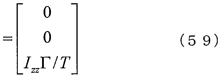
- Various methods of setting the angular momentum are conceivable.However, if it is not assumed that the motion causes the entire body to rotate largely in the air, the angular momentum during the non-contact period is set to 0 as shown in the following equation. Is the easiest.
- the body posture trajectory during the non-contact period is obtained according to the processing procedure described above, while the substrate posture trajectory during the contact period is set so that it is smoothly connected to the substrate posture trajectory during the non-contact period.
- the basic trajectory of the base attitude must be corrected.
- the body posture angular velocity becomes the value of the body posture angular velocity obtained by solving the simultaneous equations consisting of the equations (51) to (56) in this posture.
- the body attitude trajectory of the adjacent landing period immediately before the non-landing period must be corrected.
- the body posture angle matches the value of the body posture angle at the end of the non-contact period obtained by the numerical integration of the above equation (57).
- the angular velocity of the body posture becomes the value of the angular velocity of the body posture obtained by solving the simultaneous equations of equations (51) to (56) in this posture.
- the substrate attitude trajectory must be corrected.
- FIG. 10 exemplifies the relationship between the base posture basic trajectory and the base posture reference trajectory in a model in which short-term sections and short-term sections belonging to the non-contact period are mixed.
- the section i-1 in the figure corresponds to such a case. However, only the roll angle orbit is shown for simplification of the drawing.
- Section i-11 is a case where both the start and end are in contact with the non-grounded section. Not only the boundary (end) with section i but also the boundary (start) of section i-11 is as described above. Boundary conditions are imposed. For example, using a polynomial interpolation such as a spline interpolation, a base posture trajectory during a contact period can be set as a curved trajectory that satisfies the start and end conditions.
- the section i + 1 in the figure is different from the case of section i-1 1 in that the start end is adjacent to section i where there is no grounding period, but the other end is the grounding period where it is connected to grounding section i + 2 .
- the boundary (end) between section i + 2 and the boundary (end) with section i + 2 should be the position of the basic body attitude basic trajectory so that the boundary (start) with the section i satisfies the boundary condition based on the body attitude angle trajectory during the non-contact period.
- the body attitude angle trajectory in section i must be set so that the velocity is continuous.
- a curved trajectory that satisfies such a start-end condition can be set using, for example, polynomial interpolation.
- the base body posture basic trajectory may be set as it is as the reference trajectory.
- the trajectory of the body attitude angle during the grounding period adjacent to the non-contact period is not necessarily corrected from the basic trajectory as described above. Such as the time of The trajectory may be partially modified.
- the difference between the method of correcting the body attitude angle trajectory during the contact period and the method of correcting the center-of-gravity position trajectory is that the time must be sequentially processed.
- the trajectory in the non-contact section can be obtained only by numerical integration based on the above equation (57), and the boundary condition at the end of the non-contact period is determined by this number-linear integration. It is. In practice, only this numerical integration should be performed during the non-contact period, and the trajectory correction of the adjacent contact period should be performed at the boundary from the non-contact period to the contact period.
- the base body posture trajectory generating unit 33 adds to the equation (1) as the mechanical constraint in the contact period and the equation (2) as the mechanical constraint in the contactless period, It is possible to generate a base posture trajectory that satisfies the equation (3) as a target constraint.
- FIG. 11 shows, in the form of a flowchart, a processing procedure executed in the base body posture trajectory generating unit 33.
- step S21 it is determined whether or not the current time belongs to the non-contact period.
- the process proceeds to step S22, and using the sole position / posture trajectory output from the sole position / posture trajectory generation unit 31, the Jacobian constraint equation (5 1) Find (5-4).
- the angular momentum Jacobian constraint equation (56) is obtained using the angular momentum calculated before leaving the bed (step S24).
- a body posture angular trajectory in a non-contact period can be sequentially generated (step S26).
- step S21 processing is performed only when the current time corresponds to the beginning of the ground contact period (step S20).
- step S27 it is determined whether the contact period is a section adjacent to the non-contact period. If it is the contact period adjacent to the non-contact period, it is further determined whether or not the immediately adjacent short-term section is the non-contact period (step S28).
- the target angular momentum in the non-contact period is calculated based on a criterion such as the above equation (58) or (59) (step S29).
- the sole position / posture trajectory generated by the sole position / posture trajectory generation unit 31 and the center of gravity trajectory generation unit 32 generate The value at the time of leaving the calculated center of gravity position trajectory is used.
- the simultaneous linear equation consisting of the Jacobian constraint equations (51) to (56) is solved to calculate the base body posture angular velocity at the time of leaving the bed (step S33). At this point, the boundary conditions at the end of the touchdown period have been determined.
- step S34 it is determined whether or not the immediately adjacent short-term section is in the non-contact period.
- step S35 If the immediately preceding short-term section is in the non-contact period, the body posture angular velocity at the end of the non-contact period obtained as a result of step S26 is extracted as the boundary condition at the start of the contact period, so that The setting of the boundary conditions is completed (step S35).
- step S34 if it is determined in step S34 that the immediately preceding short-term section is in the touchdown period, the value of the base posture basic trajectory given by the user program is set as the boundary condition of the start point of the touchdown period. Complete the setting of the boundary conditions for (Step S38).
- step S28 if it is determined that the short-term section immediately after the touchdown period is also the touchdown period, the process proceeds to step S37, and the body posture given from the motion request input unit 3A as the boundary condition of the touchdown period end.
- the boundary conditions at the beginning of the touchdown period are set in the same way as in the case where the short-term section immediately after the touchdown period is determined to be the no-contact period in step S28. You.
- step S39 the grounding period is set so that the boundary condition is satisfied.
- a process of configuring the base body posture trajectory using a curve such as polynomial interpolation is performed. Further, if it is determined in step S27 that the contact period is not adjacent to the non-contact period, the basic posture trajectory given from the motion request input unit 3A is used as the base posture trajectory during the contact period. Therefore, in step S36, the basic body posture trajectory is set as the body posture trajectory during the touchdown period, and the process is completed.
- the description of the functional configuration of the mouth bot control system according to the present embodiment will be continued.
- the upper body joint angle reference trajectory, body posture reference trajectory, center of gravity position reference trajectory, and sole position and posture reference trajectory given by the user program can be obtained.
- interpolation units provided for each trajectory in each control cycle (upper joint angle reference trajectory interpolation unit 34, body posture reference trajectory interpolation unit 35, center of gravity position reference trajectory interpolation unit 36, plantar
- the body joint angle, the body posture angle, the center of gravity position, and the sole position / posture at each time can be calculated.
- the trajectory of the body posture angle trajectory in the non-contact period is given in the form of a numerical integration, the interpolation process in the body posture reference trajectory interpolation unit 35 is not particularly necessary.
- the mass point distribution adjusting unit 38 adjusts the mass point distribution state of the whole body so as to satisfy the base posture and the center of gravity position at the next time obtained as described above. That is, the substrate orientation, while fixing the sole position and orientation, and the upper body joint angles to the requested value, the position of the substrate (the pelvis) (x B, y B, z B) operates the center of gravity of the whole body is in the The whole body mass distribution is adjusted so that the obtained center of gravity is obtained. Under such geometric constraints, the speed between the substrate and the center of gravity is between Jacobian and T. Then, the following relationship is established.
- the manipulated variable dx B can be approximately obtained by the following equation.
- the substrate position X Bk + 1 after mass point distribution adjustment to obtain the substrate posture and the center of gravity position at the next time obtained above can be obtained by the following equation. It can. However, if the deviation between the center of gravity obtained as a result of the above equation (62) and the reference center of gravity is still large, convergence calculation is performed by repeatedly using the equation (62) until the deviation becomes sufficiently small. You may.
- the joint angle calculation unit 39 realizes the base position at the next time obtained by the mass point distribution adjustment unit 38 and the sole position and posture at the next time obtained from the sole position / posture trajectory generation unit 31. Determine the joint angles of the legs. This can be performed, for example, by calculating the relative position and orientation of the two and then using, for example, a well-known inverse kinematics calculation.
- the obtained joint angle of the leg joint and the reference joint angle of the upper body given by the user program are output as the reference value of the whole body joint angle at the next time.
- the legged moving bot can be used not only for walking, but also for jumping and running, as well as for stride and cycle in situations where these movements appear sequentially. While satisfying external demands such as the above, it is possible to operate while calculating a dynamically stable motion pattern in a responsive (or real-time) manner.
- the position of the center of gravity and the attitude angle of the base are used as the state quantities of the robot.
- this may be configured to use other state quantities.
- the effect of the present invention can be similarly obtained by using the position of a part (for example, the waist) close to the center of gravity instead of the center of gravity, or using the waist joint angle instead of the body posture angle.
- a so-called whole body cooperative control system may be configured by using an arbitrary joint angle as a state quantity.
- the whole-body motion generation processing is configured to be executed at each control cycle, but the trajectory generation is performed only when the contact state changes (both legs supported, one leg supported, ungrounded boundary).
- Steps S1 to S4 in Fig. 4 are executed, and only the processes after the trajectory interpolation processing (Steps S5 to S7 in Fig. 4) are executed for each control cycle.
- the trajectory generation processing may be configured to be executed in a longer cycle. However, in this case, the responsiveness of the exercise demand reflection decreases.
- the motion state at the current time obtained as a result of the previous whole-body motion generation processing is set as the initial condition of the next-period whole-body motion generation processing, so that the current motion state is smoothly changed.
- the exercise state to be connected has been determined, but the gist of the present invention is not limited to this.
- a pelvis acceleration sensor A 1 and a gyro mouth G 1 a sole force sensor (F 1 to F 8), a distance measurement sensor (D 1 to D 8), an acceleration sensor (A 2, A 3), and a gyro (G
- the motion state of the actual robot is measured using sensors such as (2, G3), and this is set as the initial condition. It can be configured to execute a whole body motion generation process reflecting the state.
- the gist of the present invention is not necessarily limited to products called “robots”. In other words, if a mechanical device performs a motion that resembles human motion using an electric or magnetic action, the same applies to a product belonging to another industrial field such as a toy.
- the present invention can be applied to
- an excellent motion control apparatus and a motion control method for a legged mobile robot which can generate a stable motion pattern transitioning between a ground motion and a non-ground motion in real time. can do.
- the present invention is based on the point that there are few restrictions on the mechanical model, such as the massless leg assumption (for example, Kiyotoshi Matsuoka, “Repetitive jump model. Biomechanism 5” (The University of Tokyo Press, 1998) , P. 4501—4509), and Mark. H. Rabert (Marc H. Raibert) et al. Two experiments on balance using a “three-dimensional single-leg hopping” machine (Experiments In Balancewitha 3D) one—L egged Hopping Machine) ”(International Journal of Robotics Research, The International Journal of Hot Research, 1984, Vol. 3, No. 2, p.
- the present invention it is possible to control the motion of a legged mobile robot in which grounding and non-grounding are mixed.
- Most of the conventional legged mobile robot control systems are related to walking, and few control systems have a wider range of motion control systems including non-contact periods such as running and jumping.
- the present invention extends the method based on the ZMP stability criterion (see, for example, Non-Patent Document 1) to more general movements including the non-contact period,
- the present invention is based on the ability to generate a dynamically stable movement pattern in real time, and requests for changes in lower limb movements such as stride length, step period, turning angle, and foot-height that are input asynchronously. It is possible to satisfy the demands for changes in upper body movement while maintaining the mechanical balance, and it is possible to realize flexible and diverse mixed movements without and with ground. It is extremely difficult to maintain mechanical stability while satisfying such external requirements with a method that creates motion patterns in advance offline or a conventional control system that only maintains balance.
Landscapes
- Engineering & Computer Science (AREA)
- Chemical & Material Sciences (AREA)
- Combustion & Propulsion (AREA)
- Transportation (AREA)
- Mechanical Engineering (AREA)
- Manipulator (AREA)
- Toys (AREA)
Abstract
Description



Claims
Priority Applications (3)
| Application Number | Priority Date | Filing Date | Title |
|---|---|---|---|
| EP03769977.4A EP1559519B1 (en) | 2002-11-06 | 2003-10-29 | Robot device, motion control device for robot device and motion control method |
| US10/500,372 US7400939B2 (en) | 2002-11-06 | 2003-10-29 | Robot device, motion control device for robot device and motion control method |
| AU2003280608A AU2003280608A1 (en) | 2002-11-06 | 2003-10-29 | Robot device, motion control device for robot device and motion control method |
Applications Claiming Priority (4)
| Application Number | Priority Date | Filing Date | Title |
|---|---|---|---|
| JP2002-322582 | 2002-11-06 | ||
| JP2002322582 | 2002-11-06 | ||
| JP2003-365549 | 2003-10-27 | ||
| JP2003365549A JP3599244B2 (ja) | 2002-11-06 | 2003-10-27 | ロボット装置、ロボット装置の運動制御装置並びに運動制御方法 |
Publications (1)
| Publication Number | Publication Date |
|---|---|
| WO2004041484A1 true WO2004041484A1 (ja) | 2004-05-21 |
Family
ID=32314058
Family Applications (1)
| Application Number | Title | Priority Date | Filing Date |
|---|---|---|---|
| PCT/JP2003/013870 Ceased WO2004041484A1 (ja) | 2002-11-06 | 2003-10-29 | ロボット装置、ロボット装置の運動制御装置及び運動制御方法 |
Country Status (5)
| Country | Link |
|---|---|
| US (1) | US7400939B2 (ja) |
| EP (1) | EP1559519B1 (ja) |
| JP (1) | JP3599244B2 (ja) |
| AU (1) | AU2003280608A1 (ja) |
| WO (1) | WO2004041484A1 (ja) |
Cited By (3)
| Publication number | Priority date | Publication date | Assignee | Title |
|---|---|---|---|---|
| WO2006083028A1 (en) * | 2005-02-03 | 2006-08-10 | Toyota Jidosha Kabushiki Kaisha | Legged robot and control method thereof |
| US7751935B2 (en) * | 2004-02-11 | 2010-07-06 | Samsung Electronic Co., Ltd. | Method and apparatus for controlling vibration using accelerometer |
| CN111766885A (zh) * | 2020-07-08 | 2020-10-13 | 清华大学深圳国际研究生院 | 一种四足机器人的静步态规划方法 |
Families Citing this family (48)
| Publication number | Priority date | Publication date | Assignee | Title |
|---|---|---|---|---|
| JP3833567B2 (ja) * | 2002-05-01 | 2006-10-11 | 本田技研工業株式会社 | 移動ロボットの姿勢制御装置 |
| US7698020B2 (en) * | 2003-07-11 | 2010-04-13 | Honda Motor Co., Ltd. | Method of estimating joint moment of two-legged walking mobile body |
| JP4735927B2 (ja) * | 2004-06-28 | 2011-07-27 | 独立行政法人産業技術総合研究所 | 人間型ロボットの制御装置 |
| JP4492395B2 (ja) * | 2005-03-09 | 2010-06-30 | トヨタ自動車株式会社 | 脚式ロボットとその動作制御方法 |
| US7835822B2 (en) * | 2005-03-30 | 2010-11-16 | Honda Motor Co., Ltd. | Systems and methods for controlling a legged robot using a two-phase disturbance response strategy |
| JP4595727B2 (ja) | 2005-07-22 | 2010-12-08 | ソニー株式会社 | 外力推定システム及び外力推定方法、並びにコンピュータ・プログラム |
| JP4682791B2 (ja) | 2005-10-12 | 2011-05-11 | ソニー株式会社 | 操作空間物理量算出装置及び操作空間物理量算出方法、並びにコンピュータ・プログラム |
| JP4456561B2 (ja) * | 2005-12-12 | 2010-04-28 | 本田技研工業株式会社 | 自律移動ロボット |
| JP5034235B2 (ja) | 2006-01-16 | 2012-09-26 | ソニー株式会社 | 制御システム及び制御方法、並びにコンピュータ・プログラム |
| US7788068B2 (en) * | 2006-01-31 | 2010-08-31 | Autodesk, Inc. | Transferring load information and result information between analysis and design software |
| JP4591419B2 (ja) | 2006-07-18 | 2010-12-01 | トヨタ自動車株式会社 | ロボットとその制御方法 |
| JP5319056B2 (ja) * | 2006-08-01 | 2013-10-16 | トヨタ自動車株式会社 | 燃料電池システム |
| JP4692443B2 (ja) * | 2006-09-06 | 2011-06-01 | トヨタ自動車株式会社 | 脚式ロボット |
| JP2008087141A (ja) * | 2006-10-05 | 2008-04-17 | Toyota Motor Corp | 脚式移動ロボットの動作データ作成装置及び作成方法 |
| JP4392037B2 (ja) | 2007-09-12 | 2009-12-24 | トヨタ自動車株式会社 | 脚式ロボット、及びその制御方法 |
| JP4440956B2 (ja) | 2007-09-12 | 2010-03-24 | トヨタ自動車株式会社 | 脚式ロボット、及びその制御方法 |
| KR101182620B1 (ko) * | 2007-10-23 | 2012-09-14 | 혼다 기켄 고교 가부시키가이샤 | 2 족 보행 로봇 |
| JP5035005B2 (ja) * | 2008-02-19 | 2012-09-26 | トヨタ自動車株式会社 | 脚式ロボット、その制御方法、その制御システム |
| JP2009214255A (ja) * | 2008-03-12 | 2009-09-24 | Toyota Motor Corp | 脚式ロボット、及びその制御方法 |
| TWI375140B (en) * | 2008-10-13 | 2012-10-21 | Ind Tech Res Inst | Accumulative method for estimating a processing velocity limitation and method for controlling acceleration and deceleration before interpolation |
| JP5440152B2 (ja) * | 2009-12-22 | 2014-03-12 | トヨタ自動車株式会社 | 脚式ロボットとそのための歩容データ生成方法 |
| JP5506618B2 (ja) * | 2009-12-28 | 2014-05-28 | 本田技研工業株式会社 | ロボットの制御装置 |
| KR101687628B1 (ko) * | 2010-01-12 | 2016-12-21 | 삼성전자주식회사 | 로봇의 보행 제어 장치 및 그 제어 방법 |
| JP5463991B2 (ja) * | 2010-03-18 | 2014-04-09 | トヨタ自動車株式会社 | 2脚歩行ロボット |
| KR101200191B1 (ko) * | 2010-07-14 | 2012-11-13 | 서울대학교산학협력단 | 데이터 기반 바이페드 제어 장치 및 방법 |
| WO2012011182A1 (ja) | 2010-07-22 | 2012-01-26 | トヨタ自動車株式会社 | 二足歩行ロボット及び二足歩行ロボットの着地タイミング決定方法 |
| US9024772B2 (en) | 2010-09-28 | 2015-05-05 | Xianghui Wang | Multi sensor position and orientation measurement system |
| KR20120060578A (ko) * | 2010-12-02 | 2012-06-12 | 삼성전자주식회사 | 보행 로봇 및 그 자세 제어 방법 |
| KR101778027B1 (ko) * | 2010-12-21 | 2017-09-13 | 삼성전자주식회사 | 보행 로봇 및 그 자세 제어 방법 |
| US9412010B2 (en) * | 2011-07-15 | 2016-08-09 | Panasonic Corporation | Posture estimation device, posture estimation method, and posture estimation program |
| JP5623375B2 (ja) * | 2011-12-02 | 2014-11-12 | 本田技研工業株式会社 | 脚式移動ロボットの歩容生成装置 |
| KR101428328B1 (ko) * | 2012-12-27 | 2014-08-08 | 현대자동차주식회사 | 로봇의 보행제어방법 및 시스템 |
| US8915116B2 (en) * | 2013-01-23 | 2014-12-23 | Freescale Semiconductor, Inc. | Systems and method for gyroscope calibration |
| CN103217903B (zh) * | 2013-04-07 | 2016-01-20 | 南京邮电大学 | 基于双平衡控制机制的仿人足球机器人全向踢球方法 |
| JP6330287B2 (ja) * | 2013-10-29 | 2018-05-30 | セイコーエプソン株式会社 | ロボット、ロボット用当接部材 |
| US9259838B1 (en) * | 2014-07-24 | 2016-02-16 | Google Inc. | Systems and methods for ground plane estimation |
| US9517561B2 (en) * | 2014-08-25 | 2016-12-13 | Google Inc. | Natural pitch and roll |
| US10081098B1 (en) * | 2014-08-25 | 2018-09-25 | Boston Dynamics, Inc. | Generalized coordinate surrogates for integrated estimation and control |
| CN105511465B (zh) * | 2015-12-02 | 2017-08-04 | 歌尔股份有限公司 | 一种双足机器人的步态控制方法和装置 |
| US9868210B1 (en) * | 2015-12-30 | 2018-01-16 | Google Inc. | Methods and systems for planning a body position of a robotic device |
| CN106514653B (zh) * | 2016-11-07 | 2019-01-22 | 南京邮电大学 | 一种基于贝塞尔曲线插值的仿人足球机器人踢球方法 |
| US10351189B2 (en) * | 2016-12-13 | 2019-07-16 | Boston Dynamics, Inc. | Whole body manipulation on a legged robot using dynamic balance |
| CN109634100B (zh) * | 2018-12-30 | 2021-11-02 | 深圳市优必选科技有限公司 | 仿人机器人行走加速度补偿方法、装置及仿人机器人 |
| JP7415989B2 (ja) * | 2021-03-16 | 2024-01-17 | カシオ計算機株式会社 | ロボット、ロボットの制御方法及びプログラム |
| US12509171B2 (en) | 2021-09-08 | 2025-12-30 | Ptt Exploration And Production Public Company Limited | Method and system for controlling motion of a multi-segmented walking robot |
| CN114454981B (zh) * | 2021-12-14 | 2022-11-29 | 深圳市优必选科技股份有限公司 | 双足机器人的弹跳运动控制方法、装置及双足机器人 |
| CN118131800A (zh) * | 2022-11-23 | 2024-06-04 | 北京小米机器人技术有限公司 | 运动控制方法、装置、机器人及可读储存介质 |
| CN117163182A (zh) * | 2023-08-25 | 2023-12-05 | 成都爱特生信息技术有限公司 | 一种机器人运动平衡系统及机器人 |
Citations (1)
| Publication number | Priority date | Publication date | Assignee | Title |
|---|---|---|---|---|
| WO2003057426A1 (en) | 2001-12-28 | 2003-07-17 | Honda Giken Kogyo Kabushiki Kaisha | Gait producing device for leg type movable robot |
Family Cites Families (11)
| Publication number | Priority date | Publication date | Assignee | Title |
|---|---|---|---|---|
| JP3662996B2 (ja) * | 1996-01-25 | 2005-06-22 | 本田技研工業株式会社 | 脚式移動ロボットの歩行制御装置 |
| US5872893A (en) * | 1996-07-25 | 1999-02-16 | Honda Giken Kogyo Kabushiki Kaisha | Gait generation system of legged mobile robot |
| US6243623B1 (en) * | 1997-01-31 | 2001-06-05 | Honda Giken Kogyo Kabushiki Kaisha | Leg type mobile robot control apparatus |
| US6064168A (en) * | 1998-03-13 | 2000-05-16 | Fanuc Robotics North America, Inc. | Method of controlling robot movement |
| US6289265B1 (en) * | 1998-04-20 | 2001-09-11 | Honda Giken Kogyo Kabushiki Kaisha | Controller for legged mobile robot |
| JP3555107B2 (ja) * | 1999-11-24 | 2004-08-18 | ソニー株式会社 | 脚式移動ロボット及び脚式移動ロボットの動作制御方法 |
| JP3615702B2 (ja) * | 1999-11-25 | 2005-02-02 | ソニー株式会社 | 脚式移動ロボットの動作制御装置及び動作制御方法、並びに、脚式移動ロボット |
| JP2001260063A (ja) * | 2000-03-21 | 2001-09-25 | Sony Corp | 多関節型ロボット及びその動作制御方法 |
| JP2001322079A (ja) * | 2000-05-15 | 2001-11-20 | Sony Corp | 脚式移動ロボット及びその動作教示方法 |
| JP4404639B2 (ja) * | 2002-02-15 | 2010-01-27 | ソニー株式会社 | 脚式移動ロボットの脚装置並びに脚式移動ロボットの制御方法 |
| JP4513320B2 (ja) * | 2003-12-17 | 2010-07-28 | ソニー株式会社 | ロボット装置、並びにロボット装置の運動制御方法 |
-
2003
- 2003-10-27 JP JP2003365549A patent/JP3599244B2/ja not_active Expired - Fee Related
- 2003-10-29 AU AU2003280608A patent/AU2003280608A1/en not_active Abandoned
- 2003-10-29 WO PCT/JP2003/013870 patent/WO2004041484A1/ja not_active Ceased
- 2003-10-29 US US10/500,372 patent/US7400939B2/en not_active Expired - Lifetime
- 2003-10-29 EP EP03769977.4A patent/EP1559519B1/en not_active Expired - Lifetime
Patent Citations (1)
| Publication number | Priority date | Publication date | Assignee | Title |
|---|---|---|---|---|
| WO2003057426A1 (en) | 2001-12-28 | 2003-07-17 | Honda Giken Kogyo Kabushiki Kaisha | Gait producing device for leg type movable robot |
Non-Patent Citations (1)
| Title |
|---|
| See also references of EP1559519A4 |
Cited By (5)
| Publication number | Priority date | Publication date | Assignee | Title |
|---|---|---|---|---|
| US7751935B2 (en) * | 2004-02-11 | 2010-07-06 | Samsung Electronic Co., Ltd. | Method and apparatus for controlling vibration using accelerometer |
| WO2006083028A1 (en) * | 2005-02-03 | 2006-08-10 | Toyota Jidosha Kabushiki Kaisha | Legged robot and control method thereof |
| DE112006000313B4 (de) | 2005-02-03 | 2018-05-09 | Toyota Jidosha Kabushiki Kaisha | Bebeinter Roboter und Steuerungsverfahren für denselben |
| CN111766885A (zh) * | 2020-07-08 | 2020-10-13 | 清华大学深圳国际研究生院 | 一种四足机器人的静步态规划方法 |
| CN111766885B (zh) * | 2020-07-08 | 2023-08-11 | 清华大学深圳国际研究生院 | 一种四足机器人的静步态规划方法 |
Also Published As
| Publication number | Publication date |
|---|---|
| EP1559519A1 (en) | 2005-08-03 |
| AU2003280608A1 (en) | 2004-06-07 |
| JP2004167676A (ja) | 2004-06-17 |
| EP1559519A4 (en) | 2012-01-04 |
| EP1559519B1 (en) | 2014-10-01 |
| JP3599244B2 (ja) | 2004-12-08 |
| US7400939B2 (en) | 2008-07-15 |
| US20050038560A1 (en) | 2005-02-17 |
Similar Documents
| Publication | Publication Date | Title |
|---|---|---|
| JP3599244B2 (ja) | ロボット装置、ロボット装置の運動制御装置並びに運動制御方法 | |
| US7805218B2 (en) | Robot device and control method of robot device | |
| JP5483997B2 (ja) | 脚式移動ロボットの制御装置 | |
| JP5284923B2 (ja) | 脚式移動ロボットの制御装置 | |
| Kajita et al. | Real-time 3D walking pattern generation for a biped robot with telescopic legs | |
| EP1378325B1 (en) | Legged mobile robot and control method thereof, leg structure of legged mobile robot, and mobile leg unit for legged mobile robot | |
| US7603234B2 (en) | Controller of legged mobile robot | |
| JP3640255B2 (ja) | 脚式移動ロボットの歩容生成装置 | |
| JP4641252B2 (ja) | 脚式移動ロボットの歩容生成装置 | |
| JP4513320B2 (ja) | ロボット装置、並びにロボット装置の運動制御方法 | |
| KR100718479B1 (ko) | 로봇의 보행 제어 장치 및 보행 제어 방법 | |
| WO2004033160A1 (ja) | ロボット装置の動作制御装置及び動作制御方法 | |
| WO2003061917A1 (fr) | Dispositif de commande pour robot bipede | |
| JP2004167666A (ja) | ロボット装置及びその動作制御方法 | |
| KR101760883B1 (ko) | 로봇 및 그 제어방법 | |
| JP4483254B2 (ja) | ロボット装置及びロボット装置の制御方法 | |
| US7765030B2 (en) | Gait generator for mobile robot | |
| WO2006064598A1 (ja) | 脚式移動ロボットおよびその制御プログラム | |
| JP2003117858A (ja) | ロボットの歩行制御装置及び歩行制御方法 | |
| US20090099689A1 (en) | Legged mobile robot and control program for the robot | |
| JP2002210681A (ja) | 脚式移動ロボットのための動作制御装置及び動作制御方法、並びにロボット装置 | |
| JP5232120B2 (ja) | 移動体の制御装置 | |
| JP3674787B2 (ja) | ロボット装置の動作制御装置及び動作制御方法、並びにコンピュータ・プログラム | |
| Sari et al. | Implementation and integration of fuzzy algorithms for descending stair of KMEI humanoid robot | |
| JP2003159676A (ja) | 脚式移動ロボットの制御方法 |
Legal Events
| Date | Code | Title | Description |
|---|---|---|---|
| AK | Designated states |
Kind code of ref document: A1 Designated state(s): AE AG AL AM AT AU AZ BA BB BG BR BY BZ CA CH CN CO CR CU CZ DE DK DM DZ EC EE ES FI GB GD GE GH GM HR HU ID IL IN IS KE KG KP KR KZ LC LK LR LS LT LU LV MA MD MG MK MN MW MX MZ NI NO NZ OM PH PL PT RO RU SC SD SE SG SK SL TJ TM TN TR TT TZ UA UG US UZ VC VN YU ZA ZM ZW |
|
| AL | Designated countries for regional patents |
Kind code of ref document: A1 Designated state(s): GH GM KE LS MW MZ SD SL SZ TZ UG ZM ZW AM AZ BY KG KZ MD RU TJ TM AT BE BG CH CY CZ DE DK EE ES FI FR GB GR HU IE IT LU MC NL PT RO SE SI SK TR BF BJ CF CG CI CM GA GN GQ GW ML MR NE SN TD TG |
|
| WWE | Wipo information: entry into national phase |
Ref document number: 2003769977 Country of ref document: EP |
|
| 121 | Ep: the epo has been informed by wipo that ep was designated in this application | ||
| WWE | Wipo information: entry into national phase |
Ref document number: 10500372 Country of ref document: US |
|
| WWP | Wipo information: published in national office |
Ref document number: 2003769977 Country of ref document: EP |