WO2004100731A1 - 防曇鏡 - Google Patents
防曇鏡 Download PDFInfo
- Publication number
- WO2004100731A1 WO2004100731A1 PCT/JP2004/005925 JP2004005925W WO2004100731A1 WO 2004100731 A1 WO2004100731 A1 WO 2004100731A1 JP 2004005925 W JP2004005925 W JP 2004005925W WO 2004100731 A1 WO2004100731 A1 WO 2004100731A1
- Authority
- WO
- WIPO (PCT)
- Prior art keywords
- value
- functional layer
- thickness
- fog mirror
- film
- Prior art date
- Legal status (The legal status is an assumption and is not a legal conclusion. Google has not performed a legal analysis and makes no representation as to the accuracy of the status listed.)
- Ceased
Links
Classifications
-
- G—PHYSICS
- G02—OPTICS
- G02B—OPTICAL ELEMENTS, SYSTEMS OR APPARATUS
- G02B1/00—Optical elements characterised by the material of which they are made; Optical coatings for optical elements
- G02B1/10—Optical coatings produced by application to, or surface treatment of, optical elements
- G02B1/18—Coatings for keeping optical surfaces clean, e.g. hydrophobic or photo-catalytic films
-
- A—HUMAN NECESSITIES
- A47—FURNITURE; DOMESTIC ARTICLES OR APPLIANCES; COFFEE MILLS; SPICE MILLS; SUCTION CLEANERS IN GENERAL
- A47G—HOUSEHOLD OR TABLE EQUIPMENT
- A47G1/00—Mirrors; Picture frames or the like, e.g. provided with heating, lighting or ventilating means
- A47G1/02—Mirrors used as equipment
-
- C—CHEMISTRY; METALLURGY
- C03—GLASS; MINERAL OR SLAG WOOL
- C03C—CHEMICAL COMPOSITION OF GLASSES, GLAZES OR VITREOUS ENAMELS; SURFACE TREATMENT OF GLASS; SURFACE TREATMENT OF FIBRES OR FILAMENTS MADE FROM GLASS, MINERALS OR SLAGS; JOINING GLASS TO GLASS OR OTHER MATERIALS
- C03C17/00—Surface treatment of glass, not in the form of fibres or filaments, by coating
- C03C17/34—Surface treatment of glass, not in the form of fibres or filaments, by coating with at least two coatings having different compositions
- C03C17/36—Surface treatment of glass, not in the form of fibres or filaments, by coating with at least two coatings having different compositions at least one coating being a metal
- C03C17/3602—Surface treatment of glass, not in the form of fibres or filaments, by coating with at least two coatings having different compositions at least one coating being a metal the metal being present as a layer
- C03C17/3657—Surface treatment of glass, not in the form of fibres or filaments, by coating with at least two coatings having different compositions at least one coating being a metal the metal being present as a layer the multilayer coating having optical properties
- C03C17/3663—Surface treatment of glass, not in the form of fibres or filaments, by coating with at least two coatings having different compositions at least one coating being a metal the metal being present as a layer the multilayer coating having optical properties specially adapted for use as mirrors
-
- G—PHYSICS
- G02—OPTICS
- G02B—OPTICAL ELEMENTS, SYSTEMS OR APPARATUS
- G02B27/00—Optical systems or apparatus not provided for by any of the groups G02B1/00 - G02B26/00, G02B30/00
- G02B27/0006—Optical systems or apparatus not provided for by any of the groups G02B1/00 - G02B26/00, G02B30/00 with means to keep optical surfaces clean, e.g. by preventing or removing dirt, stains, contamination, condensation
-
- G—PHYSICS
- G02—OPTICS
- G02B—OPTICAL ELEMENTS, SYSTEMS OR APPARATUS
- G02B5/00—Optical elements other than lenses
- G02B5/08—Mirrors
- G02B5/0816—Multilayer mirrors, i.e. having two or more reflecting layers
- G02B5/085—Multilayer mirrors, i.e. having two or more reflecting layers at least one of the reflecting layers comprising metal
- G02B5/0858—Multilayer mirrors, i.e. having two or more reflecting layers at least one of the reflecting layers comprising metal the reflecting layers comprising a single metallic layer with one or more dielectric layers
-
- C—CHEMISTRY; METALLURGY
- C03—GLASS; MINERAL OR SLAG WOOL
- C03C—CHEMICAL COMPOSITION OF GLASSES, GLAZES OR VITREOUS ENAMELS; SURFACE TREATMENT OF GLASS; SURFACE TREATMENT OF FIBRES OR FILAMENTS MADE FROM GLASS, MINERALS OR SLAGS; JOINING GLASS TO GLASS OR OTHER MATERIALS
- C03C2217/00—Coatings on glass
- C03C2217/40—Coatings comprising at least one inhomogeneous layer
- C03C2217/425—Coatings comprising at least one inhomogeneous layer consisting of a porous layer
-
- C—CHEMISTRY; METALLURGY
- C03—GLASS; MINERAL OR SLAG WOOL
- C03C—CHEMICAL COMPOSITION OF GLASSES, GLAZES OR VITREOUS ENAMELS; SURFACE TREATMENT OF GLASS; SURFACE TREATMENT OF FIBRES OR FILAMENTS MADE FROM GLASS, MINERALS OR SLAGS; JOINING GLASS TO GLASS OR OTHER MATERIALS
- C03C2217/00—Coatings on glass
- C03C2217/70—Properties of coatings
- C03C2217/71—Photocatalytic coatings
-
- C—CHEMISTRY; METALLURGY
- C03—GLASS; MINERAL OR SLAG WOOL
- C03C—CHEMICAL COMPOSITION OF GLASSES, GLAZES OR VITREOUS ENAMELS; SURFACE TREATMENT OF GLASS; SURFACE TREATMENT OF FIBRES OR FILAMENTS MADE FROM GLASS, MINERALS OR SLAGS; JOINING GLASS TO GLASS OR OTHER MATERIALS
- C03C2217/00—Coatings on glass
- C03C2217/70—Properties of coatings
- C03C2217/75—Hydrophilic and oleophilic coatings
Definitions
- the present invention relates to an anti-fog mirror, and more particularly, to an anti-fog mirror having a neutral reflection color.
- the anti-fog mirror is a reflecting mirror having a property of removing water droplets adhering to the mirror surface.
- Conventional anti-fog mirrors use a water repellent treatment on the mirror surface to increase the water repellency of the water and remove the adhering water droplets in a ball shape. It is broadly divided into those that enhance wettability and remove adhering water droplets by spreading them in a thin film.
- the water adhering to the surface is turned into a bead (a hemispherical shape having a small curvature) as a water droplet, and the rear image reflected on the water droplet is inverted upside down due to a lens effect.
- an antifogging mirror proposed by the present applicant, comprising a transparent photocatalytic substance film exhibiting a photocatalytic reaction on the surface of a transparent substrate member and a transparent porous inorganic oxide film.
- a transparent photocatalytic substance film exhibiting a photocatalytic reaction on the surface of a transparent substrate member and a transparent porous inorganic oxide film.
- such a conventional anti-fog mirror has a T i O 2 film as a photocatalytic substance and a S i as a porous inorganic oxide film on the front surface of a transparent glass substrate from the substrate side.
- T i O 2 film as a photocatalytic substance
- S i as a porous inorganic oxide film
- ⁇ Two films are sequentially formed, and a metal reflection film of Cr, A1, etc. is formed on the rear surface of the transparent glass substrate.
- this anti-fog mirror surface wetting water adhering to the surface of the porous S i 0 2 film exhibits a capillary action in the porous S I_ ⁇ 2 film porous openings (not shown)
- the improved hydrophilicity enhances the hydrophilicity and provides an antifogging function. Therefore, if this anti-fog mirror is applied to an outer mirror for a vehicle, a mirror for a bathroom, a window for a vehicle, a window glass, or the like, water droplets are less likely to adhere in a ball shape, and visibility is improved.
- the reflection characteristic changes depending on the thickness of T i ⁇ 2. It has various reflection colors. 6 (1), (2), (3) color, respectively, to the spectral reflectance characteristics of the anti-fogging mirror film thickness T I_ ⁇ 2 are different have exhibits these (bluish, yellowish, reddish) It is a graph shown with the a * value and b * value of the L * a * b * color system chromaticity diagram. Among them, the anti-fog mirror having a bluish color tone as shown in FIG. 6 (1) also has an anti-glare effect and is suitable for an outer mirror for automobiles.
- the reflection color can be made closer to a neutral color tone (the reflection color is small and the reflection color can be suppressed), that is, L * a * b * color system chromaticity
- a neutral color tone for reflected color that is, the a * value of the L * a * b * color system chromaticity diagram
- the present invention makes it possible to make the reflection color closer to a neutral color tone (in the region where the reflection color is almost colorless based on the a * value and b * value of the L * a * b * color system chromaticity diagram).
- the purpose is to provide an anti-fog mirror, and the reflection color has a neutral color tone (the reflection color is colorless by the a * value and b * value in the L * a * b * color system chromaticity diagram).
- Of color In the area to provide an anti-fog mirror. Disclosure of the invention
- the present inventors have proposed an anti-fog mirror having the above-described configuration, in which the reflection color is required to exhibit a colorless color tone using the a * and b * values of the L * a * b * color system chromaticity diagram as indices.
- Various investigations were performed on the conditions.
- “reflection color is colorless” means that the reflection color of the anti-fog mirror is in an area where the reflection color of the L * a * b * color system (JISZ 8729) exhibits a colorless color tone with a * and b * values.
- the spectral reflectance (the relationship between the reflectance and the wavelength of the reflected light) of the reflected light from the anti-fog mirror has no particular peak in the visible light region, and the reflected light reproduces the color of the substance as it is. It means that.
- reflection color exhibits a color tone close to colorless means that the reflection color of the anti-fog mirror is close to colorless with the a * and b * values of the L * a * b * color system (JISZ 8729).
- the spectral reflectance (the relationship between the reflectance and the wavelength of the reflected light) of the reflected light of the anti-fog mirror has no special peak in the visible light region, and the reflected light is It means that colors are almost reproduced.
- the present inventors investigated parameters affecting the spectral reflectance of the reflected light of the anti-fog mirror, and the spectral reflectance was determined by the hydrophilic functional layer and the photocatalytic functional layer provided in the anti-fog mirror. It has been clarified that the thickness largely depends on the thickness of the photocatalyst functional layer. Furthermore, the relationship between this spectral reflectance and the film thickness of the hydrophilic functional layer and the photocatalytic functional layer was investigated, and based on this relationship, the reflection color of the anti-fog mirror was made colorless.
- L * a * b * color system chromaticity diagram The inventors have found that the object can be achieved by setting the thickness of the photocatalytic functional layer so as to obtain the a * value and the b * value (or c * value) of the present invention, and have completed the present invention.
- the anti-fog mirror according to the present invention is an anti-fog mirror comprising: a metal reflecting film from the side of the base; and a composite functional layer having a photocatalytic function and a hydrophilic function, on the surface of the base.
- the thickness of the functional layer is set so that the saturation c * value represented by the following equation (1) in the L * a * b * color system chromaticity diagram is 35 or less (Configuration 2). Saturation (C
- the photocatalytic reaction of the photocatalytic substance (layer) contained in the composite functional layer prevents a decrease in hydrophilicity, and can maintain the antifogging property for a long time.
- the a * and b * values of the L * a * b * color system chromaticity diagram (or c * value), an anti-fog mirror whose reflection color is close to a neutral color tone, and eventually an anti-fog mirror whose reflection color has a neutral color tone are realized.
- the film thickness of the composite functional layer In order to make the reflected color closer to a neutral color tone (suppress the reflected color), the film thickness of the composite functional layer must be such that the a * and b * values in the L * a * b * color system chromaticity diagram It is preferable to set them so that they are 20 to 20, 20, 15 to 15, and 10 to 10, respectively.
- the thickness of the composite functional layer is such that the chroma c * value represented by the above equation (1) in the L * a * b * color system chromaticity diagram is 30 or less, 25 or less, 20 or less. , 15 or less, and preferably 10 or less.
- the thickness of the composite functional layer is set such that the a * value and b * value (or c * value) of the L * a * b * color system chromaticity diagram are set as described above.
- the color tone of the mirror surface can be changed to “smooth color tone” in the “brightness and saturation color tone diagram” in the L * a * b * color system (color tone that is achromatic and can suppress reflected colors) From the aspect exhibiting the above, to the aspect that can be called substantially colorless and transparent (more preferred aspect).
- the photocatalytic reaction is such that, when a semiconductor such as Ti ⁇ ⁇ 2 is excited at a wavelength having energy equal to or greater than its band gap, an electron-hole pair is generated inside the semiconductor.
- Holes photoexcited T I_ ⁇ 2 has a very strong oxidizing power, organic substances adhering to the surface is Ru are removed are decomposed by the photocatalytic reaction.
- the composite functional layer of the anti-fog mirror can be configured by laminating a hydrophilic functional layer on a photocatalytic functional layer (Configuration 3).
- the photocatalytic functional layer is a layer containing a photocatalytic substance or a layer substantially consisting of a photocatalytic substance.
- the hydrophilic functional layer is a layer containing a hydrophilic substance or a layer consisting essentially of a hydrophilic substance.
- the present invention provides the anti-fog mirror, wherein a reflectance adjustment is performed between the metal reflective film and the composite functional layer (photocatalytic functional layer), comprising a substance having a lower refractive index than the composite functional layer (photocatalytic functional layer).
- Layers can be provided (Configuration 4).
- the reflectance can be compensated by appropriately adjusting the thickness of the reflectance adjusting layer, and thus the a * value and b in the L * a * b * color system chromaticity diagram are obtained.
- the * value (or c * value) approaches “0”, the reflected color becomes even more colorless, and the reflected color can be made more neutral.
- the hydrophilic functional layer is constructed by a main component S I_ ⁇ 2 (substantially constituted by S I_ ⁇ 2) is preferably (Configuration 5), photocatalyst It is preferable that the functional layer is composed mainly of T i 0 2 (substantially composed of T i ⁇ 2 ) (configuration 6).
- the photocatalyst can be used. (for T I_ ⁇ 2, mainly ultraviolet) light to cause reaction is transmitted through the transparency of the porous inorganic oxide film and electrons and holes generated in the photocatalytic functional layer is porous inorganic oxide film As organic substances and N adhering to the porous openings Ox can be decomposed and removed by a photocatalytic reaction.
- the present invention provides the anti-fog mirror, wherein the metal reflection film is selected from the group consisting of Cr, ⁇ 1 "-1 ⁇ 11 alloy, Al, Rh, Ti_Rh alloy, and Ag. (Composition 7), the composite function layer (photocatalytic function layer) provided between the metal reflective film and the composite function layer (photocatalytic function layer).
- a material having a lower refractive index, Ta 2 ⁇ 5, Z R_ ⁇ 2, Sn_ ⁇ 2, ln 2 0 3, S I_ ⁇ , ZnO, a l 2 ⁇ 3, I tO, Y 2 0 3, MgO, W0 3, can be constructed of Z R_ ⁇ 2, and T i 0 1 selected from among 2 made from a group or two or more (configuration 8).
- an anti-fog mirror which exhibits a required effect in the present invention is realized.
- the distance between the metal reflection film and the mirror surface can be set short as described later, it is possible to prevent the occurrence of a double image visually. it can.
- the anti-fog mirror configured as described above can be adapted to an outer mirror for automobiles (Configuration 9) or can be adapted to a dental mirror (Configuration 10).
- FIG. 1 is a cross-sectional view schematically illustrating a configuration of an anti-fog mirror according to a first embodiment of the present invention.
- FIG. 2 is a cross-sectional view schematically illustrating a configuration of an anti-fog mirror according to a second embodiment of the present invention.
- FIG. 3 is a cross-sectional view schematically illustrating a configuration of an anti-fog mirror according to a third embodiment of the present invention.
- FIG. 4 is a cross-sectional view schematically illustrating a configuration of an anti-fog mirror according to a fourth embodiment of the present invention.
- FIG. 5 is a partially enlarged sectional view schematically showing a configuration example of a conventional anti-fog element.
- Figure 6 illustrates a * value of the L * a * b * color system chromaticity diagram exhibiting a spectral reflectance characteristic of the film thickness of T i 0 2 different anti-fog mirror each antifogging mirrors, with b * value Fig. 6 (a), (b), and (c) correspond to the a * and b * values of blue, yellow, and red tones, respectively.
- FIG. 1 is a cross-sectional view schematically illustrating a configuration of an anti-fog mirror according to a first embodiment of the present invention.
- FIG. 2 is a cross-sectional view schematically illustrating a configuration of an anti-fog mirror according to a second embodiment of the present invention.
- FIG. 3 is a cross-sectional view schematically illustrating a configuration of an anti-fog mirror according to a third embodiment of the present invention.
- FIG. 4 is a schematic view illustrating a configuration of an anti-fog mirror according to a fourth embodiment of the present invention.
- FIG. In the following description members having the same conditions will be denoted by the same reference numerals and overlapping description will be omitted.
- the first embodiment according to the present invention corresponds to Configuration 1, and as shown in FIG. 1, a base material 5, a metal reflection film 6 provided on the surface of the base material 5, and a metal reflection film It is configured as an anti-fog mirror 1 having a composite functional layer 7 having a photocatalytic function and a hydrophilic function provided on 6.
- the thickness of the composite functional layer 7 is set so that the a * value and the b * value of the L * a * b * color system chromaticity diagram are 25 to 25 (preferably 20 to 120), respectively. Is set.
- the thickness of the composite functional layer 7 is such that the saturation c * value represented by the above equation (1) in the L * a * b * color system chromaticity diagram is 35 or less (preferably 30 or less). It is set to be.
- the anti-fog mirror 1 is designed so that the a * value and b * value of the L * a * b * color system chromaticity diagram are 25 forces and -25 (or the c * value is 35 or less), respectively.
- the spectral reflectance of the reflected light does not have a special peak in the visible light region. Is designed to have a color close to neutral. As a result, the reflection color of the anti-fog mirror 1 becomes almost colorless, and the color of the substance itself can be visually recognized almost exactly.
- the anti-fog mirror 1 has the a * value and b * value of the L * a * b * color system chromaticity diagram,
- the film thickness of the composite functional layer 7 is 20 to 20 (or the saturation c * value is 30 or less)
- the spectral reflectance of reflected light Has no special peak in the visible light region, and therefore, the mirror surface is configured to exhibit a neutral color.
- the reflection color of the anti-fog mirror 1 becomes substantially colorless, and the color of the substance itself can be visually recognized accurately.
- the composite functional layer 7 exhibits hydrophilicity due to the hydrophilic functional layer contained therein, the attached water droplets are spread in a thin film to exhibit an anti-fog effect.
- organic substances such as ox, terriers, or NOx or the like in the atmosphere (hereinafter referred to as “organic substances”) adhere to this surface, sunlight or other rays (ultraviolet rays, etc.) are applied to the composite functional layer. Is irradiated to the photocatalytic substance contained in the photocatalyst, and the photocatalytic substance is photoexcited.
- the photoexcitation generates electron and hole pairs in the composite functional layer 7 (photocatalytic functional layer), which reacts with organic substances attached to the surface, and the redox reaction proceeds to decompose and remove the organic substances. Let it. Therefore, a decrease in hydrophilicity is prevented, and the antifogging property can be maintained for a long period of time.
- the present invention in order to harmonize the effect and cost of such hydrophilic function and a photocatalytic function, it is good Mashiku constituting the hydrophilic material contained in the composite functional layer 7 by S i 0 2 addition, it is preferable to configure the photocatalytic substance T I_ ⁇ 2. And, since the composite functional layer 7 is formed in a porous shape, the hydrophilic function can be further enhanced. Furthermore, the present invention does not particularly limit the form of the composite functional layer 7.
- a single photocatalytic substance having a hydrophilic function a mixture of a photocatalytic substance and a hydrophilic functional substance [photocatalytic substance and hydrophilic A structure in which functional substances are randomly mixed, a single-layer structure in which a photocatalytic substance (for example, Ti 2 ) is dispersed in a hydrophilic substance (for example, Si 2 )], a photocatalytic substance and a hydrophilic functional substance And a multilayer film structure in which are alternately stacked.
- a conventionally known film forming method can be used for forming such a composite function layer 7.
- a single layer of the photocatalytic substance having the lyophilic function is formed using only the target of Ti 2 , or a target of S i 0 2 and T i 0 2 is used.
- a multi-function device having the effects of the present invention by forming the above-mentioned multilayer film structure by forming the above two layers sequentially or alternately or by vapor deposition.
- the active layer 7 can be formed.
- the anti-fog mirror 1 has an L * a * b * color system chromaticity diagram in which the a * value and b * value are from 25 to ⁇ 25 (or the saturation c * value is 35 or less).
- the thickness of the composite functional layer 7 is adjusted so that the a * value and the b * value are from 20 to ⁇ 20 (or the saturation c * value is 30 or less). It is configured such that the color tone is close to neutral and the reflection color is close to colorless, and preferably the color tone is neutral and the reflection color is achromatic.
- the composite functional layer 7 is composed of two layers, a photocatalytic functional layer and a hydrophilic functional layer, the film thickness of the composite functional layer 7 is adjusted by appropriately adjusting the thickness of either or one of the two. It can be carried out.
- the metal reflection film 6 included in the anti-fog mirror according to the present invention is mainly composed of Cr, Cr-Rh alloy, A-Rh, Ti-Rh alloy, and Ag in terms of cost. It is preferable to be composed of one or more selected from the group. The same applies to other embodiments.
- the anti-fog mirror 1 according to the present invention is not particularly limited with respect to the base material, and various types of conventionally known glass plates or various types of conventionally-known glass plates or various kinds of glass may be used so as to appropriately match required characteristics such as strength, smoothness, and cost. It can be selected from materials such as a metal plate.
- a conventionally known soda lime glass can be used as a base material. The same applies to other embodiments.
- the second embodiment according to the present invention corresponds to Configuration 3, and as shown in FIG. 2, a base material 5, a metal reflection film 6 provided on the surface of the base material 5, and a metal reflection film
- the anti-fog mirror 2 is provided with a composite functional layer 7 provided on 6 and having a photocatalytic functional layer 8 and a hydrophilic functional layer 9 formed sequentially.
- the film thickness of the composite functional layer 7 is such that the a * value and the b * value of the L * a * b * color system chromaticity diagram are from 25 to ⁇ 25 (or the saturation c * value is 3 5 or less).
- the a * and b * values Each is set so that it is between 20 and 20 (or the saturation c * value is 30 or less).
- the present inventors have investigated the parameters that affect the spectral reflectance of the reflected light from the anti-fog mirror, and found that the composite functional layer 7 has a photocatalytic functional layer and a hydrophilic functional layer. In the case of the two layers (see Fig. 2), it was clarified that it greatly depends on the thickness of the photocatalytic layer 8 in particular.
- the value required for the photocatalytic function layer 8 at which the value and the b * value (20 to 120) or the c * value (30 or less) can be obtained is relatively easy. Can be determined.
- the anti-fog mirror 2 is designed so that the a * value and b * value of the L * a * b * color system chromaticity diagram are from 25 to ⁇ 25 (or the saturation c * value is 35 or less).
- the film thickness of the photocatalytic functional layer 8 and the hydrophilic functional layer 9 is set so that the a * value and the b * value are from 20 to 120 (or the saturation c * value is 30 or less).
- the color tone becomes closer to neutral and the reflection color becomes closer to colorless (the mirror surface also becomes colorless).
- the color tone becomes neutral and the reflection color becomes colorless (mirror surface). Is also colorless).
- the reflection color of the anti-fog mirror 2 becomes almost colorless, and the color of the substance itself can be visually recognized almost exactly. More preferably, the reflection color of the anti-fog mirror 2 is colorless. Thus, the color of the substance itself can be visually recognized accurately.
- the anti-fog mirror 2 since the anti-fog mirror 2 exhibits hydrophilicity by the hydrophilic functional layer 9, it spreads the attached water droplets into a thin film to exhibit an anti-fog effect, and even if organic substances or the like are attached to the surface, the When the light (ultraviolet rays or the like) is irradiated on the photocatalytic function layer 8, the photocatalytic reaction proceeds as described above in the photocatalytic function layer 8 to decompose and remove organic substances and the like. Therefore, a decrease in hydrophilicity is prevented, and the antifogging property can be maintained for a long time. Wear.
- the hydrophilic functional layer 9 in order to harmonize with such effects and cost, it is preferred to constitute the hydrophilic functional layer 9 at S i 0 2, also, it is preferable that the photocatalytic functional layer 8 in T I_ ⁇ 2 . Further, since the hydrophilic functional layer 9 is formed in a porous shape, the hydrophilic function can be further enhanced.
- the hydrophilic functional layer is preferably a transparent porous inorganic oxide film, and more preferably, the porous opening of the porous inorganic oxide film is formed on the surface of the photocatalyst reactant film.
- the porous form must have a shape and size that does not affect the light interference effect. With this configuration, a higher hydrophilic function can be obtained due to the porous nature of the surface of the hydrophilic functional layer.
- the photocatalytic reaction can occur.
- T I_ ⁇ 2 mainly UV
- rays cause is transmitted through the transparent multi-porous shaped inorganic oxide film, electrons and holes generated in the photocatalytic functional layer is a multi-porous shaped inorganic oxide film Therefore, organic substances and NOx that have entered the porous openings and adhered can be decomposed and removed by a photocatalytic reaction.
- the third embodiment according to the present invention corresponds to Configuration 4, and as shown in FIG. 3, a base material 5, a metal reflection film 6 provided on the base material 5, and a metal reflection film 6, a reflectance adjusting layer 10 made of a substance having a lower refractive index than the composite function layer 7 (photocatalytic substance), and a photocatalytic function provided on the reflectance adjusting layer 10. and configured as anti-fog mirror 3 provided with the composite functional layer 7 (e.g. T i 0 2 composite functional layer 7 consisting solely) that combines both the effect of the hydrophilic functional layer.
- the composite functional layer 7 e.g. T i 0 2 composite functional layer 7 consisting solely
- the film thickness of the composite functional layer 7 is such that the a * value and the b * value of the L * a * b * color system chromaticity diagram are from 25 to ⁇ 25 (or the saturation c * value is 35 or less, respectively).
- the anti-fog mirror 3 is provided with the metal reflective film 6 of the anti-fog mirror 1 of the first embodiment and Since the reflection adjusting layer 10 made of a material having a lower refractive index than the composite function layer 7 (photocatalytic substance contained in the composite function layer 7) is added between the active layer 7 and the composite function layer 7, The description of the parts having the same numbers as those of the components of the first embodiment already described is omitted.
- the reflectance of the reflectance adjusting layer 10 is adjusted by appropriately setting the film thickness so that the a * value and b * value (or c * value) of the L * a * b * color system chromaticity diagram are “ As the value approaches "0", the reflection color becomes more and more colorless, and is added to make the reflection color more neutral.
- the adjustment of the reflectance is performed by appropriately setting the thickness of the reflectance adjusting layer 10. Table 1 shows the refractive indices of the various reflectance adjusting layers used in the present invention.
- the fourth embodiment according to the present invention corresponds to Configuration 4, and as shown in FIG. 4, a photocatalytic functional layer in which a base material 5 and a metal reflective film 6 are provided on the base material 5 8 (photocatalytic substance)
- a reflectance adjusting layer 10 made of a substance having a lower refractive index, and a photocatalytic functional layer 8 and a hydrophilic functional layer 9 provided on the reflectance adjusting layer 10 are sequentially formed.
- the anti-fog mirror 4 is provided with the composite function layer 7 formed.
- the film thickness of the composite functional layer 7 is such that the a * value and the b * value of the L * a * b * color system chromaticity diagram are from 25 to 1 25 (or the saturation c * value is 3 5
- the a * value and the b * value are each set to 20 to 120 (or the saturation c * value is 30 or less).
- the antifogging mirror 4 has a lower refractive index than the photocatalytic function layer 8 (photocatalytic substance) between the metal reflection film 6 and the photocatalytic function layer 8 of the antifogging mirror 2 of the second embodiment.
- a reflectance adjusting layer 10 made of a substance having the same is added, and has the effects described in the second and third embodiments.
- Examples 11 to 14 have a configuration corresponding to the first embodiment shown in FIG.
- a metal reflective film 6 made of Cr (film thickness lOO nm) is provided on a substrate 5 made of glass (see Fig. 1), and a composite functional layer made of Ti 2 alone is provided on the metal reflective film 6.
- 7 is an anti-fog mirror 1 formed by forming a film 7 in a range of 50 to 300 nm in increments of 10 nm.
- the thickness of the composite functional layer 7 consisting of T I_ ⁇ 2 in Table 2, L * a * b * color system chromaticity diagram a * and b * values (hereinafter, simply "a * value and b straight” ) And the saturation c * value (hereinafter, simply referred to as “c * value”).
- Example 1_1 according to the present invention, as shown in Table 2, both a * value and b * value are 25 to 25 No. 1104, 1105, 1106, 1119, 1 1 20, 1 124, 1 is 125 (T i 0 2 film each has a thickness of, 80, 90, 100, 230 , 240, 280, 290 nm).
- both a * value and b * value are 20 to -20.No. 1104, 1105, 1106, 1119, 1125 (The thickness of the TiO 2 film is 80, 90, 100, 230, 290 nm).
- T I_ ⁇ 2 film each has a thickness of, 70, 80, 90, 100, 110, 130, 140, 220, 230, 240, 250, 280, 290, 300 nm).
- T i 0 2 film each has a thickness of, 70, 80, 90, 100, 110, .140, and 230, 240, 250, 29 0 , 300 nm).
- No. 1 104, 1 105, 1 106, 1 1 1 9, 1 125 (T i 0 2 film each has a thickness of, 80, 90, 100, 230 , 290 nm) is.
- Example 1-2 a metal reflective film 6 (thickness lOO nm) made of Rh was provided on a substrate 1 (see FIG. 1) made of glass.
- ⁇ This is an anti-fog mirror 1 in which a composite functional layer 7 composed of 2 alone is formed in a film thickness range of 50 to 30 O nm in increments of 10 nm.
- Table 3 shows the T I_ ⁇ 2 alone having a thickness, a * and b * values, the relationship between c * value.
- Examples 1 and 2 according to the present invention show that both the a * value and the b * value are 2 as shown in Table 3.
- the thicknesses of the TiO 2 film are 60, 70, 80, 90, 100, 180, 240, 280, 290, and 300 nm, respectively).
- the thickness of the Ti ⁇ 2 film is 50, 60,
- the thickness of the TiO 2 film is 50, 60, 70, 80, 90, 100
- Example 1-3 a metal reflective film 6 (thickness lOO nm) made of A1 was provided on a glass substrate 5 (see FIG. 1).
- I_ ⁇ 2 alone or Ranaru composite functional layer 7 is antifog mirror 1 was deposited on 10 nm increments thickness in the range of 50-30 O nm.
- T I_ ⁇ 2 in Table 4 a * and b * values, the relationship between c * value to indicate.
- Example 13 As shown in Table 4, both the a * value and the b * value are 20 to 120, and the c * value is 30 or less. . are all 130 1 ⁇ 1326 (T i 0 2 film ranges film thickness of 50 to 300 nm) of.
- Example 1-4 a metal reflective film 6 (thickness lOO nm) made of Ag was provided on a substrate 1 (see FIG. 1) made of glass, and Ti was formed on the metal reflective film 6.
- a metal reflective film 6 thickness lOO nm
- Ti was formed on the metal reflective film 6.
- Example 14 according to the present invention, as shown in Table 5, both a * value and b * value are 20 ⁇ -20, c * value is 30 or less, No . are all 1401 ⁇ 1426 (T i 0 2 film ranges film thickness of 50 to 300 nm) of.
- Examples 2-1 to 2-4 correspond to the second embodiment as shown in FIG. Things.
- the metal reflective layer 6 provided on the substrate 5 T i 0 2 consists of the photocatalytic functional layer 8 and S I_ ⁇ 2 consisting of hydrophilic functional layer 9 on this metal reflection film 6 is constituted by sequentially laminating I have.
- Example 2-1 a metal reflective film 6 (thickness lOO nm) made of Cr was provided on a substrate 1 (see FIG. 2) made of glass.
- I_ ⁇ 2 photocatalytic functional layer 8 and S i 0 2 consists of hydrophilic functional layer 9 are sequentially laminated Ru Tona, T I_ ⁇ to 10 nm increments the 2 photocatalytic functional layer 8 consisting of thickness in the range of 50 to 300 nm
- the anti-fog mirror 2 was formed.
- Example 2_1 in Table 6, both the a * value and the b * value are 25 to 125 (preferably 20 to -20), and the c * value is 35 or less (good Mashiku 30 or less) and has a a each sample that have a thickness of T I_ ⁇ 2 film corresponding to sample No..
- Example 2-2 a metal reflective film 6 (thickness lOO nm) made of Rh was provided on a substrate 5 made of glass (see FIG. 2). ⁇ ⁇ 2 That a photocatalytic function layer 8 was deposited in 10 nm increments thickness in the range of 50-30 onm, are anti-fog mirror 2 formed by laminating a hydrophilic functional layer 9 consisting of S I_ ⁇ 2 (film thickness 20 nm) on this .
- Table 7 shows the film thickness of T i 0 2, a * and b * values, the relationship between c * value.
- Example 2-2 in Table 7, both the a * value and the b * value were 25 to -25 (preferably 20 to -20), and the c * value was 35 or less ( good Mashiku has become 30 or less), is the sample that have a thickness of T i 0 2 film corresponding to sample No.. (Example 2-3)
- Example 2-3 a metal reflection film 6 (thickness lOO nm) made of A1 was provided on a glass substrate 5 (see FIG. 2).
- the i O 2 Tona Ru photocatalytic functional layer 8 was deposited in 10 nm increments thickness in the range of 50-30 O nm, laminating a hydrophilic functional layer 9 consisting of S i 0 2 on the (film thickness 20 nm) This is the anti-fog mirror 2.
- Table 8 shows the thickness of the T I_ ⁇ 2, a * and b * values, the relationship between c * value.
- Example 2-3 in Table 8, both the a * value and the b * value were 25 to 125 (preferably 20 to -20), and the c * value was 35 or less ( good Mashiku has become 30 or less), it is all of No. 2301 ⁇ 2326 (T i 0 2 ranges film thickness of 50 to 300 nm of the film).
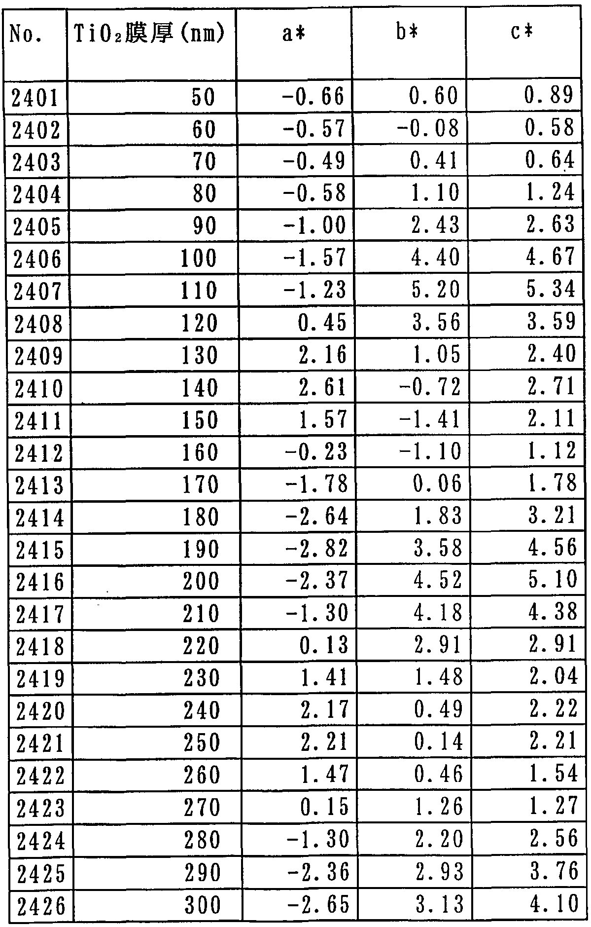
- Example 2-4 a gold substrate made of Ag was placed on a substrate 5 made of glass (see FIG. 2).
- a metal reflective film 6 (thickness lOO nm) is provided, and a photocatalytic functional layer 8 made of Ti 2 is formed on this metallic reflective film 6 in a range of 50 to 300 nm in increments of 10 nm.
- Ru anti-fog mirror 2 der as a laminate of hydrophilic functional layer 9 (thickness 20 nm) consisting of S I_ ⁇ 2 thereon.
- Table 9 shows the thickness of the T I_ ⁇ 2, a * and b * values, the relationship between c * value.
- Example 2-4 in Table 9, both the a * value and the b * value are 25 to 125 (preferably 20 to 120), and the c * value is 35 or less (good Mashiku has become 30 or less), all No. 2401 ⁇ 2426 (T I_ ⁇ 2 film Is in the range of 50 to 300 nm).
- Examples 3-1 to 3-1-11 correspond to the anti-fog mirror 4 of the fourth embodiment shown in FIG. 4, respectively.
- Example 3-1 a metal reflective film 6 (thickness l O Onm) made of Cr was provided on a base material 5 made of glass (see FIG. 4).
- a 2 ⁇ 5 the reflectance adjusting layer 10 (thickness 30 nm) provided Ru Tona, ranging photocatalytic functional layer 8 consisting of T i 0 2 on this reflectivity adjustment layer 10 having a thickness of 50 to 300 nm and film in 10 nm increments, a defogging mirror 4 as a laminate of hydrophilic functional layer 9 (thickness 20 nm) consisting of S I_ ⁇ 2 thereon.
- Table 10 shows the thickness of the T I_ ⁇ 2, a * and b * values, the relationship between c * value.
- Example 3-1 in Table 10, both the a * value and the b * value are 25 to -25 (preferably 20 to 120), and the c * value is 35 or less.
- a respective sample preferably 30 or less and has a to have a thickness of T I_ ⁇ 2 film corresponding to sample No..
- Example 3-2 a metal reflection film 6 (thickness lOO nm) made of C'r was provided on a base material 5 made of glass (see FIG. 4).
- T a 2 0 5 Tona Reflectivity adjustment layer 10 (film thickness 40 nm) provided that, T I_ ⁇ a photocatalytic function layer 8 made of 2 was deposited in 10 nm increments thickness in the range of 50 to 300 nm, S I_ ⁇ 2 on this
- the anti-fog mirror 4 is formed by laminating a hydrophilic functional layer 9 (film thickness: 20 nm) made of Table 1 1 shows the thickness of T i ⁇ 2, a * and b * values, the relationship between c * value.
- Table 1 1 substrate (force 'Las) / Cr; 100nm / Ta 2 0s: 40nm / Ti0 2; 50- 300nm / SiO 2: 20nm of a * value, b * value, c * value
- Example 3_2 in Table 11, both the a * value and the b * value are 25 to 25 (preferably 20 to 120), and the c * value is 35 or less.
- a respective sample preferably 30 or less and has a to have a thickness of T I_ ⁇ 2 film corresponding to sample No.. (Example 3 _ 3)
- Example 3-3 a metal reflective film 6 (thickness lOO nm) made of Cr was provided on a substrate 5 made of glass (see FIG. 4).
- T i ⁇ 2 in Table 12 a * and b * values, the relationship between c * value indicates.
- Example 3-3 in Table 12, both the a * value and the b * value are 25 to -25 (preferably 20 to 120), and the c * value is 35 or less.
- a respective sample preferably 30 or less and has a to have a thickness of T i 0 2 film corresponding to sample No..
- Example 3-4 a metal reflective film 6 (thickness lOO nm) made of Cr was provided on a base material 5 made of glass (see FIG. 4).
- r 0 2 Tona Ru reflectivity adjustment layer 10 (thickness 30 nm) formed, deposited on 10 nm increments a photocatalytic function layer 8 consisting of T i O 2 thickness in the range of 50 to 300 nm, on the is anti-fog mirror 4 as a laminate of hydrophilic functional layer 9 consisting of S I_ ⁇ 2 (film thickness 20 nm) on.
- T i 0 2 Table 13, a * and b * values, showing the relationship between the c * value.
- Example 3-5 a metal reflective film 6 (thickness lOO nm) made of Cr was provided on a base material 5 made of glass (see FIG. 4).
- Reflectivity adjustment layer 10 film thickness 40 nm
- T I_ ⁇ a photocatalytic function layer 8 made of 2 was deposited in 10 nm increments thickness in the range of 50 to 300 nm, S I_ ⁇ 2 on this
- the anti-fog mirror 4 is formed by laminating a hydrophilic functional layer 9 (film thickness: 20 nm) made of Table 14 shows the thickness of T i 0 2, a * and b * values, the relationship between c * value.
- Example 3-5 in Table 14, both the a * value and the b * value are 25 to 125 (preferably 20 to 120), and the c * value is 35 or less. (preferably 30 or less) has a, have a thickness of T i 0 2 film corresponding to sample No. These are the samples to be tested.
- a metal reflective film 6 (thickness lOO nm) made of Cr was provided on a base material 5 made of glass (see FIG. 4).
- R_ ⁇ 2 reflectivity adjustment layer 10 (thickness 50 nm) provided Ru Tona, forming a photocatalytic functional layer 8 consisting of T i O 2 to 10 nm increments thickness in the range of 50 to 300 nm, on the in a anti-fog mirror 4 as a laminate of hydrophilic functional layer 9 (thickness 20 nm) made of S i 0 2.
- Table 1 5 shows the film thickness of T i ⁇ 2, a * and b * values, the relationship between c * value.
- Example 3-6 in Table 15, both the a * value and the b * value are 25 to 125 (preferably 20 to 120), and the c * value is 35 or less.
- a respective sample preferably 30 or less and has a to have a thickness of T I_ ⁇ 2 film corresponding to sample No..
- Example 3-7 a metal reflective film 6 (thickness lOO nm) made of Cr was provided on a substrate 5 made of glass (see FIG. 4).
- tO Print ⁇ beam tin oxide
- a reflectivity adjustment layer 10 (thickness 40 nm) provided consisting, 1 O nm to T i 0 2 or Ranaru photocatalytic functional layer 8 thickness in the range of 50-30 O nm deposited at intervals, are anti-fog mirror 4 as a laminate of hydrophilic functional layer 9 (thickness 20 nm) made of S i 0 2 thereon.
- Table 16 shows the thickness of the T I_ ⁇ 2, a * and b * values, the relationship between c * value.
- Example 3-8 a metal reflective film 6 (thickness lOO nm) made of Cr was provided on a substrate 5 made of glass (see FIG. 4).
- 0 Inge A reflectance adjustment layer 10 (film thickness of 50 nm) made of Pd tin oxide) is provided, and a photocatalytic layer 8 of Ti 2 is formed in a film thickness of 50 to 300 nm in increments of 10 nm. and a anti-fog mirror 4 as a laminate of hydrophilic functional layer 9 (thickness 20 nm) made of S i 0 2 thereon.
- Table 17 shows the thickness of T i 0 2, a * and b * values, the relationship between c * value.
- Table 17 Substrate (force 'W) / Cr; 100iiffl / ITO; 50nni / Ti0 2; 50-300nni / Si0 2; 20mi ⁇ a lb lc fi
- Example 3-8 in Table 17, both the a * value and the b * value are 25 to 125 (preferably 20 to 120), and the c * value is 35 or less. (preferably 30 or less) has a, have a thickness of T i 0 2 film corresponding to sample No. These are the samples to be tested.
- Example 3-9 a metal reflective film 6 made of Cr (film thickness lOO nm) was provided on a base material 5 made of glass (see FIG. 4).
- tO (Print ⁇ beam tin oxide) reflectivity adjustment layer 10 (film thickness 200 nm) provided consisting, T i 0 becomes 10 nm increments the 2 photocatalytic functional layer 8 consisting of thickness in the range of 50 to 300 nm
- the anti-fog mirror 4 is formed by forming a film and laminating a hydrophilic functional layer 9 (film thickness: 20 nm) made of Si 2 on this.
- the thickness of T i 0 2 Table 18, a * and b * values, the table 18 showing the relationship between c * value
- Example 3-9 in Table 18, both the a * value and the b * value are 25 to 125 (preferably 20 to 120), and the c * value is 35 or less.
- a respective sample preferably 30 or less and has a to have a thickness of T i 0 2 film corresponding to sample No..
- Example 3-10 a metal reflective film 6 (thickness lOO nm) made of Cr was provided on a substrate 5 made of glass (see FIG. 4).
- 2 ⁇ 3 reflectivity adjustment layer 10 (thickness 30 nm) provided Ru Tona, deposited on 10 nm increments a photocatalytic function layer 8 consisting of T i 0 2 thickness in the range of 50 to 300 nm, on the From S i ⁇ 2
- the anti-fog mirror 4 is formed by laminating a hydrophilic functional layer 9 having a thickness of 20 nm. And the thickness of T i ⁇ 2 in Table 19, a straight and b straight, showing the relationship between the c directly.
- Example 3-10 in Table 19, both the a * value and the b * value are 25 to 125 (preferably 20 to 120), and the c * value is 35 or less.
- a respective sample (preferably 30 or less) has a has a thickness of T i 0 2 film corresponding to sample No..
- Example 3-11 a metal reflective film 6 (thickness lOO nm) made of Cr was provided on a substrate 5 made of glass (see FIG. 4). 2 0 3 Tona the reflectance adjusting layer 10 (thickness 40 nm) provided Ru, photocatalytic functional layer 8 consisting of T I_ ⁇ 2 was formed in 10 nm increments thickness in the range of 50 300 nm, an anti-fog mirror 4 as a laminate of hydrophilic functional layer 9 (thickness 20 nm) consisting of S I_ ⁇ 2 thereon.
- Table 20 shows the thickness of T i ⁇ 2, a * and b * values, the relationship between c * value.
- Example 3-11 in Table 20, both the a * value and the b * value are 25 to 25 (preferably 20 to 20), and the c * value is 35 or less.
- a respective sample (preferably 30 or less) has a has a thickness of T i 0 2 film corresponding to sample No..
- EXAMPLE 3 12 on a substrate 5 made of glass (see Fig. 4), provided with a metal reflective film 6 made of C r (thickness l OO nm), Y 2 on the metal reflective layer 6 ⁇ 3 Tona reflectivity adjustment layer 10 (film thickness 50 nm) provided Ru, formed to 10 nm increments a photocatalytic function layer 8 consisting of T I_ ⁇ 2 thickness in the range of 50 to 300 nm, on the This is an anti-fog mirror 3B in which a hydrophilic functional layer 9 (film thickness 20 nm) made of Si 2 is laminated. Table 21 shows the thickness of the T I_ ⁇ 2, a * and b * values, the relationship between c * value.
- Example 3-12 in Table 21, both the a * value and the b * value are 25 to -25 (preferably 20 to -20), and the c * value is 35 or less. (Preferably 3 0 or less) and going on, each sample having a thickness of T i 0 2 film corresponding to the sample N o..
- the anti-fog mirror according to the present invention has the composite function layer 7 formed on the metal reflection film 6, and the composite function layer 7 is composed of T i 0 2 having both a photocatalytic function and a hydrophilic function layer, Example 1 in which the film thickness is in the range of 50 to 300 nm (see FIG. 1), or the composite functional layer 7 is composed of the photocatalytic functional layer 8 and the hydrophilic functional layer 9, Example 2 (see FIG. 2) in which 20 ⁇ m is 50 to 300 nm, or a reflectance adjusting layer 10 is formed between the metal reflective film 6 and the composite function layer 7 in Example 2 above.
- Example 1 in which the film thickness is in the range of 50 to 300 nm (see FIG. 1), or the composite functional layer 7 is composed of the photocatalytic functional layer 8 and the hydrophilic functional layer 9, Example 2 (see FIG. 2) in which 20 ⁇ m is 50 to 300 nm, or a reflectance adjusting layer 10 is formed between the metal reflective film 6 and the composite function layer 7 in
- the reflection color exhibits a neutral color tone or a color tone close to a neutral (L * a * b * color system chromaticity diagram a * value and b * value in a colorless color region or a colorless color region).
- L * a * b * color system chromaticity diagram a * value and b * value in a colorless color region or a colorless color region.
- the anti-fog mirror according to the present invention provides a neutral color tone by appropriately setting the film thickness of the composite function layer 7, and the metal reflection film 6 and the mirror surface (the composite function layer 7) , That is, the sum of the film thickness of the composite functional layer 7 (the film thickness of the photocatalytic functional layer 8 and the film thickness of the hydrophilic functional layer 9) and the film thickness of the reflectance adjusting layer 10 is appropriately set short. By doing so, it is possible to prevent the occurrence of a double image visually.
- Photocatalytic performance after beat drops engine oil Example shown in Table 22 A, B, to each sample of C, and ultraviolet radiation at an intensity of 1. OmWZcm 2, followed by dropwise addition of water to these samples, The contact angle was measured and evaluated. Table 23 shows the results.
- the sample of each of the examples according to the present invention was immersed in tap water and boiled.
- a boiling test was performed for 2 hours. After this test, the appearance of each sample was evaluated to evaluate the adhesion between the film and the substrate (glass).
- the sample subjected to the boiling test was irradiated with ultraviolet light for 24 hours at an intensity of 1.0 mWZ cm 2 for 24 hours, and a water drop was dropped on the surface of the sample to measure the contact angle. evaluated. The results are shown in Table 24.
- Example A of the present invention B, either C, even after boiling test using the tap water, the film (S 1 0 2 Oyobihinoto 1_Rei 2) was not observed at all separation of the adhesion between the film and the substrate (glass) was good.
- the contact angle was 10 ° or less.
- Example 1 Example 2, and Example 3 having the configurations of the first, second, and fourth embodiments according to the present invention have been described above.
- the present invention is not limited to only these examples, and those having the configuration of the third embodiment according to the present invention can provide the same effects as these examples. According to the present invention configured as described above, the following effects can be obtained.
- an antifogging mirror having a composite functional layer having a metal reflective film and a photocatalytic function and a hydrophilic functional layer on the surface of the substrate from the substrate side Therefore, even if water adheres to the surface of the anti-fog mirror, the hydrophilic function included in the composite functional layer constituting the surface spreads the water, so that the water does not easily become a ball-shaped water droplet.
- the photocatalytic substance contained in the functional layer or the photocatalytic reaction of the photocatalytic functional layer prevents a decrease in hydrophilicity and can maintain the antifogging property for a long period of time.
- the hydrophilic functional layer is formed by being laminated on the photocatalytic functional layer, even if water adheres to the hydrophilic functional layer provided on the surface of the anti-fog mirror, Water droplets are hardly formed by the hydrophilic functional layer, and a photocatalytic reaction in the photocatalytic functional layer provided under the parenthesis prevents a decrease in hydrophilicity and provides an anti-fog mirror capable of maintaining anti-fog properties for a long period of time. Can be provided.
- a reflectance adjusting layer made of a substance having a lower refractive index than the composite functional layer (photocatalytic functional layer) is provided.
- the reflectance can be compensated by appropriately adjusting the thickness of the reflectance adjusting layer, and the a * value and b * value of the L * a * b * color system chromaticity diagram ( Or c * value) approaches “0” and the reflection color becomes more colorless, thereby providing an anti-fog mirror capable of making the reflection color more neutral.
- the hydrophilic functional layer is composed of S I_ ⁇ 2
- rays causing photocatalytic reaction is transmitted through the transparent S I_ ⁇ second film, also occur in the photocatalytic functional layer (photocatalytic material) and the electron or the hole is transmitted through the membrane of the S I_ ⁇ 2, the minute opening of the S I_ ⁇ second film
- the organics or NO x that has adhered can provide anti-fog mirror that can be removed by by connexion decomposed into photocatalytic reaction at silicon.
- the photocatalytic functional layer or the photocatalytic material is constituted by T i O 2, mainly ultraviolet causing photocatalytic reaction transparent S I_ ⁇ 2 layers
- T i O 2 mainly ultraviolet causing photocatalytic reaction transparent S I_ ⁇ 2 layers
- organic substances the electrons and holes passes through a layer of S I_ ⁇ 2, attached to a layer of S I_ ⁇ 2
- An anti-fog mirror capable of decomposing and removing NOx and NOx by a photocatalytic reaction can be provided.
- the metal reflective film is one or a member selected from the group consisting of Cr, 1 "-1111 alloy, A1, Rh, Ti—Rh alloy, and Ag. Since it is composed of two or more types, it is possible to provide an anti-fog mirror capable of exhibiting the expected effect of the present invention.
- the composite functional layer (photocatalytic functional layer) provided between the metal reflective film and the composite functional layer (photocatalytic functional layer) has a lower refractive index than that of the composite functional layer (photocatalytic functional layer).
- the distance between the metal reflection film and the mirror surface can be set short, so that the occurrence of a double image visually can be prevented.
Landscapes
- Physics & Mathematics (AREA)
- Chemical & Material Sciences (AREA)
- Chemical Kinetics & Catalysis (AREA)
- General Physics & Mathematics (AREA)
- Optics & Photonics (AREA)
- Engineering & Computer Science (AREA)
- Life Sciences & Earth Sciences (AREA)
- General Chemical & Material Sciences (AREA)
- Geochemistry & Mineralogy (AREA)
- Materials Engineering (AREA)
- Organic Chemistry (AREA)
- Optical Elements Other Than Lenses (AREA)
- Mirrors, Picture Frames, Photograph Stands, And Related Fastening Devices (AREA)
- Rear-View Mirror Devices That Are Mounted On The Exterior Of The Vehicle (AREA)
- Surface Treatment Of Glass (AREA)
Abstract
Description


Claims
Priority Applications (3)
| Application Number | Priority Date | Filing Date | Title |
|---|---|---|---|
| EP04729270A EP1623657A4 (en) | 2003-05-14 | 2004-04-23 | MIRROR WITH ANTI-FIT COATING |
| JP2005506161A JPWO2004100731A1 (ja) | 2003-05-14 | 2004-04-23 | 防曇鏡 |
| US10/547,308 US20060077549A1 (en) | 2003-05-14 | 2004-04-23 | Anti-fog mirror |
Applications Claiming Priority (2)
| Application Number | Priority Date | Filing Date | Title |
|---|---|---|---|
| JP2003135907 | 2003-05-14 | ||
| JP2003-135907 | 2003-05-14 |
Publications (1)
| Publication Number | Publication Date |
|---|---|
| WO2004100731A1 true WO2004100731A1 (ja) | 2004-11-25 |
Family
ID=33447202
Family Applications (1)
| Application Number | Title | Priority Date | Filing Date |
|---|---|---|---|
| PCT/JP2004/005925 Ceased WO2004100731A1 (ja) | 2003-05-14 | 2004-04-23 | 防曇鏡 |
Country Status (5)
| Country | Link |
|---|---|
| US (1) | US20060077549A1 (ja) |
| EP (1) | EP1623657A4 (ja) |
| JP (1) | JPWO2004100731A1 (ja) |
| CN (1) | CN1767777A (ja) |
| WO (1) | WO2004100731A1 (ja) |
Cited By (7)
| Publication number | Priority date | Publication date | Assignee | Title |
|---|---|---|---|---|
| JP2007286491A (ja) * | 2006-04-19 | 2007-11-01 | Murakami Corp | 有色防曇鏡 |
| JP2008268109A (ja) * | 2007-04-24 | 2008-11-06 | Shimizu Corp | 測量システム |
| JP2011033714A (ja) * | 2009-07-30 | 2011-02-17 | Nippon Electric Glass Co Ltd | 光反射基材 |
| JP2011107189A (ja) * | 2009-11-12 | 2011-06-02 | Tokai Rika Co Ltd | 反射鏡 |
| JP2012032643A (ja) * | 2010-07-30 | 2012-02-16 | Tokai Kogaku Kk | 鏡 |
| WO2014162909A1 (ja) * | 2013-03-31 | 2014-10-09 | 株式会社 村上開明堂 | 有色防曇鏡 |
| WO2018216122A1 (ja) * | 2017-05-23 | 2018-11-29 | 株式会社島津製作所 | 耐熱性反射鏡、ガス濃度モニタ及び耐熱性反射鏡の製造方法 |
Families Citing this family (12)
| Publication number | Priority date | Publication date | Assignee | Title |
|---|---|---|---|---|
| WO2007115796A2 (de) * | 2006-04-07 | 2007-10-18 | Interpane Entwicklungs- Und Beratungsgesellschaft Mbh & Co. Kg | Witterungsbeständiges schichtsystem |
| US7892662B2 (en) | 2006-04-27 | 2011-02-22 | Guardian Industries Corp. | Window with anti-bacterial and/or anti-fungal feature and method of making same |
| JP2008233878A (ja) * | 2007-02-20 | 2008-10-02 | Hoya Corp | 防塵性反射鏡及びそれを具備する光学系装置 |
| US20110051241A1 (en) * | 2009-09-01 | 2011-03-03 | Ilvento Gregory A | Anti-fog screen and methods |
| FR2964722B1 (fr) * | 2010-09-15 | 2015-11-06 | Saint Gobain | Panneau miroir et eclairant a diodes electroluminescentes |
| CN102525389A (zh) * | 2011-11-30 | 2012-07-04 | 复旦大学 | 一种防雾口腔镜 |
| US9409380B2 (en) | 2014-10-31 | 2016-08-09 | Mcs Industries, Inc. | Anti-fog mirror apparatus having a multi-layer film |
| US9770688B2 (en) * | 2015-10-22 | 2017-09-26 | King Fahd University Of Petroleum And Minerals | Si—Y nanocomposite membrane and methods of making and use thereof |
| CN120630360A (zh) * | 2017-04-12 | 2025-09-12 | 富士胶片株式会社 | 防反射膜及光学部件 |
| US10611679B2 (en) | 2017-10-26 | 2020-04-07 | Guardian Glass, LLC | Coated article including noble metal and polymeric hydrogenated diamond like carbon composite material having antibacterial and photocatalytic properties, and/or methods of making the same |
| CN109534692B (zh) * | 2019-01-24 | 2022-01-04 | 福建工程学院 | 一种抗划伤除污光催化玻璃及其制备方法 |
| CN110215031A (zh) * | 2019-07-01 | 2019-09-10 | 丹阳市精通眼镜技术创新服务中心有限公司 | 一种带防雾镜片的眼镜盒及其制作方法 |
Citations (5)
| Publication number | Priority date | Publication date | Assignee | Title |
|---|---|---|---|---|
| JPS62108207A (ja) * | 1985-11-06 | 1987-05-19 | Tokai Rika Co Ltd | 着色鏡 |
| JPH04285034A (ja) * | 1991-03-14 | 1992-10-09 | Tokai Rika Co Ltd | ブロンズ色ミラー |
| JPH1036144A (ja) * | 1996-07-26 | 1998-02-10 | Murakami Corp | 防曇素子 |
| JP2001141916A (ja) * | 1999-11-12 | 2001-05-25 | Murakami Corp | 有色防曇鏡 |
| JP2001245765A (ja) * | 2000-03-08 | 2001-09-11 | Toto Ltd | 鏡 |
Family Cites Families (11)
| Publication number | Priority date | Publication date | Assignee | Title |
|---|---|---|---|---|
| FR2704545B1 (fr) * | 1993-04-29 | 1995-06-09 | Saint Gobain Vitrage Int | Vitrage muni d'une couche fonctionnelle conductrice et/ou basse-émissive. |
| JP2000053449A (ja) * | 1998-08-06 | 2000-02-22 | Murakami Corp | 防曇鏡およびその製造方法 |
| JP2000155344A (ja) * | 1998-11-20 | 2000-06-06 | Murakami Corp | エレクトロクロミック素子 |
| US6480335B1 (en) * | 1999-01-19 | 2002-11-12 | Kabushiki Kaisha Tokai-Rika-Denki-Seisakusho | Reflecting mirror |
| JP2000347013A (ja) * | 1999-04-02 | 2000-12-15 | Nippon Sheet Glass Co Ltd | 親水性鏡及びその製造方法 |
| US6193378B1 (en) * | 1999-06-25 | 2001-02-27 | Gentex Corporation | Electrochromic device having a self-cleaning hydrophilic coating |
| JP3372527B2 (ja) * | 2000-05-17 | 2003-02-04 | 株式会社村上開明堂 | 複合材 |
| FR2814094B1 (fr) * | 2000-09-20 | 2003-08-15 | Saint Gobain | Substrat a revetement photocatalytique et son procede de fabrication |
| EP1405718A1 (en) * | 2001-06-11 | 2004-04-07 | Murakami Corporation | Antifogging element and method for forming the same |
| EP1398146A1 (en) * | 2001-06-11 | 2004-03-17 | Murakami Corporation | Antifogging element and method for forming the same |
| US6766817B2 (en) * | 2001-07-25 | 2004-07-27 | Tubarc Technologies, Llc | Fluid conduction utilizing a reversible unsaturated siphon with tubarc porosity action |
-
2004
- 2004-04-23 JP JP2005506161A patent/JPWO2004100731A1/ja not_active Withdrawn
- 2004-04-23 EP EP04729270A patent/EP1623657A4/en not_active Withdrawn
- 2004-04-23 US US10/547,308 patent/US20060077549A1/en not_active Abandoned
- 2004-04-23 WO PCT/JP2004/005925 patent/WO2004100731A1/ja not_active Ceased
- 2004-04-23 CN CN200480008985.7A patent/CN1767777A/zh active Pending
Patent Citations (5)
| Publication number | Priority date | Publication date | Assignee | Title |
|---|---|---|---|---|
| JPS62108207A (ja) * | 1985-11-06 | 1987-05-19 | Tokai Rika Co Ltd | 着色鏡 |
| JPH04285034A (ja) * | 1991-03-14 | 1992-10-09 | Tokai Rika Co Ltd | ブロンズ色ミラー |
| JPH1036144A (ja) * | 1996-07-26 | 1998-02-10 | Murakami Corp | 防曇素子 |
| JP2001141916A (ja) * | 1999-11-12 | 2001-05-25 | Murakami Corp | 有色防曇鏡 |
| JP2001245765A (ja) * | 2000-03-08 | 2001-09-11 | Toto Ltd | 鏡 |
Non-Patent Citations (1)
| Title |
|---|
| See also references of EP1623657A4 * |
Cited By (9)
| Publication number | Priority date | Publication date | Assignee | Title |
|---|---|---|---|---|
| JP2007286491A (ja) * | 2006-04-19 | 2007-11-01 | Murakami Corp | 有色防曇鏡 |
| JP2008268109A (ja) * | 2007-04-24 | 2008-11-06 | Shimizu Corp | 測量システム |
| JP2011033714A (ja) * | 2009-07-30 | 2011-02-17 | Nippon Electric Glass Co Ltd | 光反射基材 |
| JP2011107189A (ja) * | 2009-11-12 | 2011-06-02 | Tokai Rika Co Ltd | 反射鏡 |
| JP2012032643A (ja) * | 2010-07-30 | 2012-02-16 | Tokai Kogaku Kk | 鏡 |
| WO2014162909A1 (ja) * | 2013-03-31 | 2014-10-09 | 株式会社 村上開明堂 | 有色防曇鏡 |
| JP2014202759A (ja) * | 2013-03-31 | 2014-10-27 | 株式会社村上開明堂 | 有色防曇鏡 |
| WO2018216122A1 (ja) * | 2017-05-23 | 2018-11-29 | 株式会社島津製作所 | 耐熱性反射鏡、ガス濃度モニタ及び耐熱性反射鏡の製造方法 |
| JPWO2018216122A1 (ja) * | 2017-05-23 | 2020-01-16 | 株式会社島津製作所 | 耐熱性反射鏡、ガス濃度モニタ及び耐熱性反射鏡の製造方法 |
Also Published As
| Publication number | Publication date |
|---|---|
| EP1623657A4 (en) | 2006-08-23 |
| EP1623657A1 (en) | 2006-02-08 |
| CN1767777A (zh) | 2006-05-03 |
| US20060077549A1 (en) | 2006-04-13 |
| JPWO2004100731A1 (ja) | 2006-07-13 |
Similar Documents
| Publication | Publication Date | Title |
|---|---|---|
| WO2004100731A1 (ja) | 防曇鏡 | |
| JP3701826B2 (ja) | 有色防曇鏡 | |
| CN101059569B (zh) | 着色防雾镜 | |
| JP3593682B2 (ja) | 運転席側ミラーおよび自動車用アウターミラー | |
| KR100749429B1 (ko) | 반사 방지 코팅 및 코팅된 물품 | |
| BE1011444A3 (fr) | Substrat revetu de metal. | |
| JP4147743B2 (ja) | 光吸収性反射防止体とその製造方法 | |
| CN1125996C (zh) | 具有眩光控制的波长选择应用薄膜 | |
| US20130070340A1 (en) | Antireflective coating and substrates coated therewith | |
| EP1916547B1 (en) | Mirror and hydrophilic composite film having photo catalyst activity | |
| JP2003503264A (ja) | 自動クリーニング親水性コーティングを持つ電気光学装置 | |
| TW200304414A (en) | Composite material | |
| JP2008541168A (ja) | 制御された表面形態をもつ自己清掃の親水性コーティングを有するエレクトロクロミックデバイス | |
| JP4184830B2 (ja) | 複合材 | |
| CN100363173C (zh) | 复合材料 | |
| EP1022588A1 (en) | Hydrophilic mirror | |
| JPH08268732A (ja) | 熱線反射ガラス | |
| JPH1045435A (ja) | 低反射ガラス | |
| JP2877554B2 (ja) | 車両用の反射低減ガラス | |
| JPH06345490A (ja) | 紫外線遮蔽ガラス | |
| JPH06329443A (ja) | 紫外線熱線遮断ガラス | |
| JPH0748145A (ja) | 自動車用ウインドガラス及び自動車用ウインドガラスに対する被膜形成方法 | |
| JPH0710608A (ja) | 紫外線熱線遮断ガラス | |
| JPH06330288A (ja) | 熱線反射薄膜 |
Legal Events
| Date | Code | Title | Description |
|---|---|---|---|
| AK | Designated states |
Kind code of ref document: A1 Designated state(s): AE AG AL AM AT AU AZ BA BB BG BR BW BY BZ CA CH CN CO CR CU CZ DE DK DM DZ EC EE EG ES FI GB GD GE GH GM HR HU ID IL IN IS JP KE KG KP KR KZ LC LK LR LS LT LU LV MA MD MG MK MN MW MX MZ NA NI NO NZ OM PG PH PL PT RO RU SC SD SE SG SK SL SY TJ TM TN TR TT TZ UA UG US UZ VC VN YU ZA ZM ZW |
|
| AL | Designated countries for regional patents |
Kind code of ref document: A1 Designated state(s): BW GH GM KE LS MW MZ SD SL SZ TZ UG ZM ZW AM AZ BY KG KZ MD RU TJ TM AT BE BG CH CY CZ DE DK EE ES FI FR GB GR HU IE IT LU MC NL PL PT RO SE SI SK TR BF BJ CF CG CI CM GA GN GQ GW ML MR NE SN TD TG |
|
| 121 | Ep: the epo has been informed by wipo that ep was designated in this application | ||
| WWE | Wipo information: entry into national phase |
Ref document number: 2005506161 Country of ref document: JP |
|
| WWE | Wipo information: entry into national phase |
Ref document number: 2004729270 Country of ref document: EP |
|
| ENP | Entry into the national phase |
Ref document number: 2006077549 Country of ref document: US Kind code of ref document: A1 |
|
| WWE | Wipo information: entry into national phase |
Ref document number: 10547308 Country of ref document: US |
|
| WWE | Wipo information: entry into national phase |
Ref document number: 20048089857 Country of ref document: CN |
|
| WWP | Wipo information: published in national office |
Ref document number: 2004729270 Country of ref document: EP |
|
| WWP | Wipo information: published in national office |
Ref document number: 10547308 Country of ref document: US |
|
| WWW | Wipo information: withdrawn in national office |
Ref document number: 2004729270 Country of ref document: EP |