WO2005001633A2 - Interface for sending synchronized audio and video data - Google Patents
Interface for sending synchronized audio and video data Download PDFInfo
- Publication number
- WO2005001633A2 WO2005001633A2 PCT/US2004/018648 US2004018648W WO2005001633A2 WO 2005001633 A2 WO2005001633 A2 WO 2005001633A2 US 2004018648 W US2004018648 W US 2004018648W WO 2005001633 A2 WO2005001633 A2 WO 2005001633A2
- Authority
- WO
- WIPO (PCT)
- Prior art keywords
- frame
- audio
- data
- header
- computer
- Prior art date
- Legal status (The legal status is an assumption and is not a legal conclusion. Google has not performed a legal analysis and makes no representation as to the accuracy of the status listed.)
- Ceased
Links
Classifications
-
- H—ELECTRICITY
- H04—ELECTRIC COMMUNICATION TECHNIQUE
- H04N—PICTORIAL COMMUNICATION, e.g. TELEVISION
- H04N21/00—Selective content distribution, e.g. interactive television or video on demand [VOD]
- H04N21/20—Servers specifically adapted for the distribution of content, e.g. VOD servers; Operations thereof
- H04N21/23—Processing of content or additional data; Elementary server operations; Server middleware
- H04N21/236—Assembling of a multiplex stream, e.g. transport stream, by combining a video stream with other content or additional data, e.g. inserting a URL [Uniform Resource Locator] into a video stream, multiplexing software data into a video stream; Remultiplexing of multiplex streams; Insertion of stuffing bits into the multiplex stream, e.g. to obtain a constant bit-rate; Assembling of a packetised elementary stream
- H04N21/23602—Multiplexing isochronously with the video sync, e.g. according to bit-parallel or bit-serial interface formats, as SDI
-
- H—ELECTRICITY
- H04—ELECTRIC COMMUNICATION TECHNIQUE
- H04N—PICTORIAL COMMUNICATION, e.g. TELEVISION
- H04N21/00—Selective content distribution, e.g. interactive television or video on demand [VOD]
- H04N21/40—Client devices specifically adapted for the reception of or interaction with content, e.g. set-top-box [STB]; Operations thereof
- H04N21/41—Structure of client; Structure of client peripherals
- H04N21/4104—Peripherals receiving signals from specially adapted client devices
- H04N21/4126—The peripheral being portable, e.g. PDAs or mobile phones
-
- H—ELECTRICITY
- H04—ELECTRIC COMMUNICATION TECHNIQUE
- H04N—PICTORIAL COMMUNICATION, e.g. TELEVISION
- H04N21/00—Selective content distribution, e.g. interactive television or video on demand [VOD]
- H04N21/40—Client devices specifically adapted for the reception of or interaction with content, e.g. set-top-box [STB]; Operations thereof
- H04N21/41—Structure of client; Structure of client peripherals
- H04N21/414—Specialised client platforms, e.g. receiver in car or embedded in a mobile appliance
- H04N21/4143—Specialised client platforms, e.g. receiver in car or embedded in a mobile appliance embedded in a Personal Computer [PC]
-
- H—ELECTRICITY
- H04—ELECTRIC COMMUNICATION TECHNIQUE
- H04N—PICTORIAL COMMUNICATION, e.g. TELEVISION
- H04N21/00—Selective content distribution, e.g. interactive television or video on demand [VOD]
- H04N21/40—Client devices specifically adapted for the reception of or interaction with content, e.g. set-top-box [STB]; Operations thereof
- H04N21/43—Processing of content or additional data, e.g. demultiplexing additional data from a digital video stream; Elementary client operations, e.g. monitoring of home network or synchronising decoder's clock; Client middleware
- H04N21/434—Disassembling of a multiplex stream, e.g. demultiplexing audio and video streams, extraction of additional data from a video stream; Remultiplexing of multiplex streams; Extraction or processing of SI; Disassembling of packetised elementary stream
- H04N21/4342—Demultiplexing isochronously with video sync, e.g. according to bit-parallel or bit-serial interface formats, as SDI
-
- H—ELECTRICITY
- H04—ELECTRIC COMMUNICATION TECHNIQUE
- H04N—PICTORIAL COMMUNICATION, e.g. TELEVISION
- H04N21/00—Selective content distribution, e.g. interactive television or video on demand [VOD]
- H04N21/40—Client devices specifically adapted for the reception of or interaction with content, e.g. set-top-box [STB]; Operations thereof
- H04N21/43—Processing of content or additional data, e.g. demultiplexing additional data from a digital video stream; Elementary client operations, e.g. monitoring of home network or synchronising decoder's clock; Client middleware
- H04N21/436—Interfacing a local distribution network, e.g. communicating with another STB or one or more peripheral devices inside the home
- H04N21/4363—Adapting the video stream to a specific local network, e.g. a Bluetooth® network
- H04N21/43632—Adapting the video stream to a specific local network, e.g. a Bluetooth® network involving a wired protocol, e.g. IEEE 1394
-
- H—ELECTRICITY
- H04—ELECTRIC COMMUNICATION TECHNIQUE
- H04N—PICTORIAL COMMUNICATION, e.g. TELEVISION
- H04N7/00—Television systems
- H04N7/24—Systems for the transmission of television signals using pulse code modulation
- H04N7/52—Systems for transmission of a pulse code modulated video signal with one or more other pulse code modulated signals, e.g. an audio signal or a synchronizing signal
- H04N7/54—Systems for transmission of a pulse code modulated video signal with one or more other pulse code modulated signals, e.g. an audio signal or a synchronizing signal the signals being synchronous
Definitions
- the present invention relates broadly to devices in communication over a network. Specifically, the present invention relates to transmitting data in frames characterized by the presence of a header, followed by a block of video data, and a block of audio data that follows the block of video data.
- a "bus” is a collection of signals interconnecting two or more electrical devices that permits one device to transmit information to one or more other devices.
- busses used in computers and computer-related products. Examples include the Peripheral Component Interconnect (“PCI”) bus, the Industry Standard Architecture (“ISA”) bus and Universal Serial Bus (“USB”), to name a few.
- PCI Peripheral Component Interconnect
- ISA Industry Standard Architecture
- USB Universal Serial Bus
- the operation of a bus is usually defined by a standard which specifies various concerns such as the electrical characteristics of the bus, how data is to be transmitted over the bus, how requests for data are acknowledged, and the like.
- Standardizing a bus protocol helps to ensure effective communication between devices connected to the bus, even if such devices are made by different manufacturers. Any company wishing to make and sell a device to be used on a particular bus, provides that device with an interface unique to the bus to which the device will connect. Designing a device to particular bus standard ensures that device will be able to communicate properly with all other devices connected to the same bus, even if such other devices are made by different manufacturers.
- an internal fax/modem i.e., internal to a personal computer
- a PCI bus will be able to transmit and receive data to and from other devices on the PCI bus, even if each device on the PCI bus is made by a different manufacturer.
- a bus interface that permits such equipment to be connected to other equipment with a corresponding bus interface.
- digital cameras, digital video recorders, digital video disks ("DVDs"), printers are becoming available with an LEEE 1394 bus interface.
- the IEEE Institute of Electrical and Electronics Engineers 1394 bus
- digital televisions can be coupled to a computer or computer network via an IEEE 1394 bus.
- SUMMARY OF THE INVENTION The present invention solves the problems discussed above by providing a data stream format for transmission of data frames between a computer and a video client.
- the computer and video client are in communication with each other through an interface connected between the computer and the video client.
- the data stream comprises data frames transmitted sequentially, with each data frame having a frame header, video data following the frame header, and audio data following the video data.
- the data frame also includes an audio header presented between the video data and the audio data.
- a frame count synchronization bit may be included, which is synchronized with the vertical blanking portion.
- the audio header comprises an audio cycle count.
- the audio data is sampled with respect to the video data.
- the audio data comprises an audio sample count per frame, the audio sample count per frame.
- the audio sample count indicates a number of bytes per sample, and can vary in accordance with an ANSI/SMPTE 272M specification.
- the frame header may also include format flags that indicate a number of bits per sample of video data.
- the frame header comprises an SMPTE time code, and an incrementing frame counter, and an audio cycle count that indicates the position in the audio cadence specified by the ANSI/SMPTE 272M specification.
- the frame header comprises an audio channel count, and a block size byte count that indicates how many bytes of audio are contained in the audio data. Audio format flags and video format flags may also be included in the frame header.
- the present invention provides a method of data transmission, the method comprising attaching a header to an SDTI-compliant frame; and transmitting the header and SDTI-compliant frame between a video client and a computer over a IEEE 1394b-compliant interface.
- the SDTI-compliant frame is divided into first and second portions and sending the header and a portion over a first channel, and sending the header and second portion over a second channel.
- FIG.l illustrates in block diagram form major components used in connection with embodiments of the present invention
- FIG. 2 illustrates the format of a frame in accordance with embodiments of the present invention
- FIGS. 3 A and 3B illustrate the format of the first data packet and following data packet, respectively
- FIGS. 4 A and 4B illustrate the organization of video data within data packets in accordance with the embodiments of the present invention
- FIGS. 5 A and 5B illustrate the organization of audio data within data packets in accordance with the embodiments of the present invention
- FIGS. 6 and 7 illustrate elements of a header included in the frame in accordance with embodiments of the present invention
- FIG. 1 illustrates in block diagram form major components used in connection with embodiments of the present invention
- FIG. 2 illustrates the format of a frame in accordance with embodiments of the present invention
- FIGS. 3 A and 3B illustrate the format of the first data packet and following data packet, respectively
- FIGS. 4 A and 4B illustrate the organization of video data within data packets in accordance with the embodiment
- FIG. 8 illustrates a collection of packets that combine to form a frame in accordance with embodiments of the present invention
- FIGS. 9A-9D illustrates an alternative embodiment of the present invention in which variations of SDTI frames are used in accordance with embodiments of the present invention
- FIG. 9E illustrates an alternative embodiment in which the transmitter divides the SDTI stream across multiple channels
- FIG. 10 illustrates in flow chart form acts performed to provide external clocking between a computer and a hardware interface in accordance with embodiments of the present invention
- FIG. 11 illustrates the register memory map for the interface device in accordance with embodiments of the present invention
- FIG. 12 illustrates organization of A/V global registers contained within the interface of the present invention
- FIG. 13 illustrates organization of global status registers contained within the interface device of the present invention
- FIG. 14 illustrates the isochronous control register contained in the interface device of the present invention
- FIG. 15 illustrates the organization of the flow control register contained in the interface device of the present invention
- FIG. 16 illustrates the organization of the isochronous channel register contained in the interface device of the present invention.
- Computer 100 in the preferred embodiment is a computing device capable of processing and video and audio data and displaying it in a recognizable form to a user. Such devices include desktop, laptop, and palmtop computers.
- Client 102 as referred to herein is a video consumer or video producer, and includes such devices as digital cameras, and video storage devices, such as linear and random access devices.
- Bus 104 as referred to herein, includes a physical connection between computer 100 and interface 106, as well as the serial protocol adhered to by devices communicating over bus 104.
- bus 104 utilizes the IEEE 1394 serial bus protocol known as Firewire.
- Interface 106 accepts from client 102 both analog and digital inputs, and converts the input to scanned lines that can be used by an audio/video player executed on computer 100.
- interface 106 accepts from client 102 a digital compressed/uncompressed signal and transmits the entire signal or subsets of that signal.
- interface 106 divides the input into frames 108 them over bus 104 to computer 100.
- the format of frame 108 is illustrated in FIG. 2.
- Frame 108 includes a frame header 110, video block 112, audio block 114, and optionally an audio header 116. Audio data in audio block 114 is sampled with respect to the video data in video block 112.
- the audio sample count per frame varies in accordance with the number defined in the ANSI/SMPTE 272M specification, incorporated herein by reference in its entirety.
- the audio sample count cadence is necessary to divide the integer number of samples per second across the NTSC frame rate (29.97 fps ).
- the size of frame 108 can vary to accommodate various video formats such as PAL or NTSC, and 8 or 10 bit video data, and audio formats such as 48Khz and 96Khz 16 and 24 bit etc.
- the frame size of compressed data can vary to accommodate the compressed format.
- video block 112 and audio block or compressed block are of a predetermined size, to make parsing frame 108 simple and requiring little processing overhead by applications such as direct memory access programs.
- video block 112 or audio block 114 In the event that not all of video block 112 or audio block 114 is not completely full of data, the remaining portions of blocks 112, 114 can be filled with zeros.
- data contained in video block 112 and audio block 114 is not compressed, further reducing processing overhead on interface 106, as well as processing overhead required by decompression programs running on computer 100.
- Interface 106 upon converting the input received from client 102 and converting it to scan lines and organizing it into frames 108, sends a frame at each vertical blanking interval to provide synchronization with computer 100.
- Computer 100 can derive the vertical blanking interval from the frequency of frames received and synchronize itself with the audio and video data of the incoming frames 108 received from interface 106.
- FIGS. 3 A and 3B illustrate the format of the first data packet and following data packet, respectively.
- FIGS. 4 A and 4B illustrate the organization of video data within data packets.
- FIGS. 5A and 5B illustrate the organization of audio data within data packets.
- FIG. 6 illustrates the contents of frame header 110. Included are format flags 130, which indicate how many bits per sample, SMPTE time code 132, incrementing frame counter 134, audio cycle count 136, audio sample count 138, channel count 140, block size byte count 142, audio format flags 144, and video format flags 146.
- Audio sample count 138 indicates a number of samples, which is in accordance with a cadence.
- the value in audio cycle count 136 indicates location within the cadence.
- a cadence of frames form a cycling pattern.
- some of the contents of frame header 110 can be moved or copied to optional audio header 116.
- An alternative view of frame header 110 is shown in FIG. 7, showing byte count, data length, and a frame bit.
- frame 108 is constructed from a plurality of packets 150 of a predetermined size. Associated with each packet is a 1394 isochronous packet header. Data transmission in accordance with the present invention takes advantage of a synchronization bit to find the beginning of a frame. The first packet in frame 108 is marked with the synchronization bit.
- frames adhering to the serial digital interface (SDI) standard can be utilized as illustrated in FIGS, 9 A through 9E.
- bus 104 adheres to the LEEE 1394B serial bus protocol to accommodate data rate restrictions set forth by the SDI standard.
- interface 106 forms frames from received input by creating scanned lines, performing deinterlacing, packetizing, and creating fixed-size SDTI frames of audio and video data.
- Various modifications can be made to SDTI frames, depending on the processing resources available on computer 100, interface 106, client 102, or other device.
- SDTI frame 160 generally has two components: vertical blanking portion 162 and horizontal retrace 164.
- SDI frame header 166 a header having a synchronization bit and a frame count, is added to SDTI frame 160 for further synchronization and fault detection purposes, such as recovering from data lost in transmission or the occurrence of a bus reset.
- a frame count synchronization bit is included in SDTI frame header 166 and SDTI frame header 166 is synchronized with vertical blanking portion 162.
- SDTI frame 160 can be transmitted to computer 100, where processing on the SDTI stream is performed by software in a non-realtime manner.
- SDTI frame 160 can be constructed without horizontal retrace 164 to further reduce processing overhead.
- An SDTI frame constructed without a horizontal retrace but having header 166 can also be utilized in an embodiment, as shown in FIG. 9D.
- the SDTI frame can be split between multiple channels and also include SDTI frame header 166.
- the transmitter splits the SDTI stream in half, with half of the lines being transmitted across channel A, the other half being transmitted across channel B.
- An attached header for each partial frame can be used to assist in re-combining frame data.
- external clocking can be utilized to synchronize data transmission between computer 100, interface 106 and client 102.
- client 102 includes a high-quality reference clock 180 (FIG.l) that can be used to synchronize clock 182 on interface 106 and prevent overflow of buffer 184 on interface 106.
- the value of reference clock 180 on client 102 is derived on interface 106 from the frequency at which data is transmitted from computer 102 to interface 106. To perform flow control, cycles are skipped between transmission of frames.
- a skipped cycle increases the amount of time between transmissions of frames, to slow the data rate of the frame transmission.
- computer polls interface 106 to read the size of buffer 184. While for exemplary purposes the buffer is referred to in terms such as “bigger” and “smaller,” it is to be understood that in the case of a fixed-size buffer bigger and smaller refer to fullness of the buffer.
- computer 100 then sends a plurality of frames to interface 106.
- computer 100 again polls interface 106 to determine the size of buffer 184.
- control proceeds to reference numeral 208, where computer 100 increases the delay between frames it is sending to interface 106.
- the delay between frames sent is 125 milliseconds.
- a fractional delay is attained by modulating the delay over a number of frames. For instance if a delay between frames of 2.5 times 1.25microseconds is required, alternating frame delays of 2 and 3 cycles (of 125microseconds) are interspersed. Control then returns to reference numeral 202, where the frames are sent to interface 106 with the additional delay between frames.
- Interface 106 includes a serial unit 300 for enabling communication across bus 104.
- Serial unit 300 includes a unit directory 302 as shown in Table 1.
- the Unit_Spec_ID value specifies the organization responsible for the architectural definition of serial unit 300.
- the Unit_SW_Version value in combination with Unit_Spec_ID value, specifies the software interface of the unit.
- the Unit_Register_location value specifies the offset in the target device's initial address space of the serial unit registers.
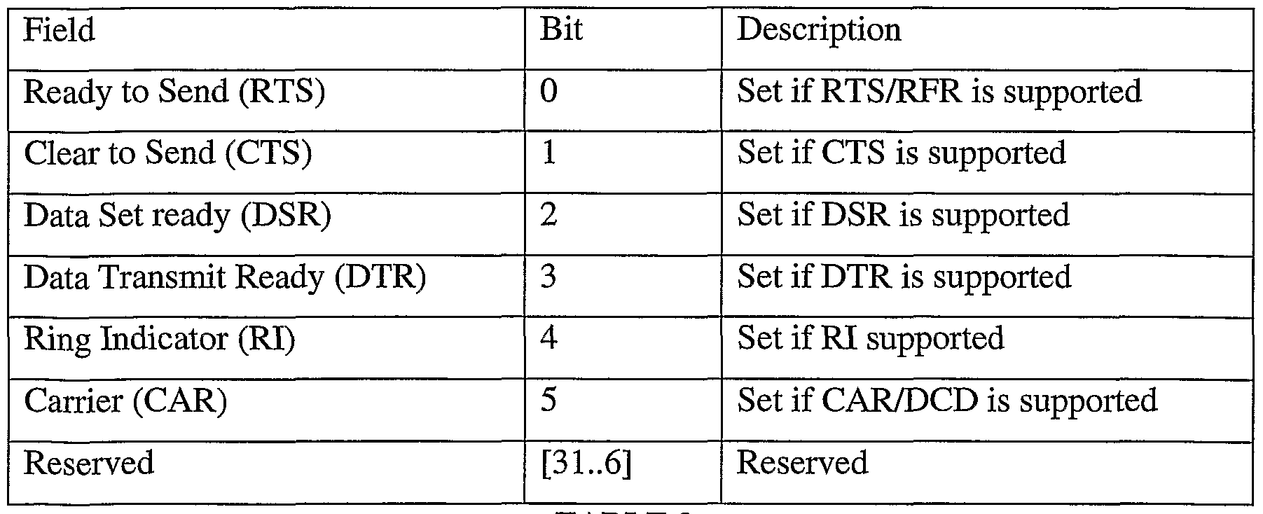
- the Unit_Signals_Supported value specifies which RS-232 signals are supported, as shown in the Table 2. If this entry is omitted from the serial unit directory 302, then none of these signals are supported.
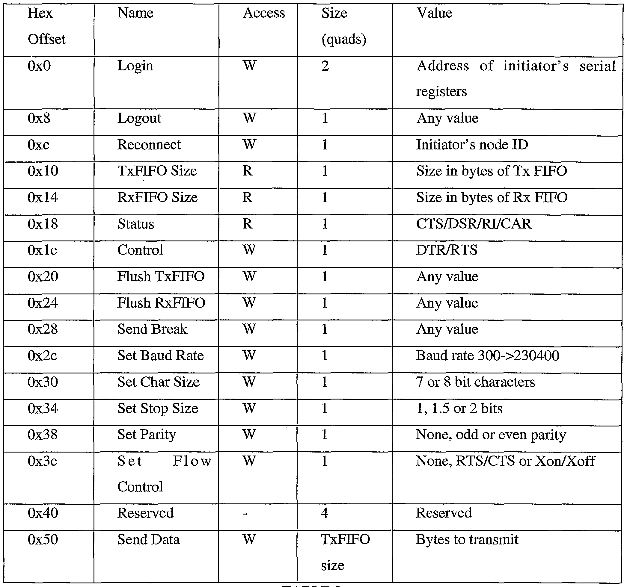
- serial unit 300 Also included in serial unit 300 is a serial unit register map 304 that references registers contained in serial unit 300.
- the organization of serial unit register map 304 is shown in Table 3.
- Serial unit register map 304 references a login register.
- a device attempting to communicate with serial unit 300 is referred to herein as an initiator.
- an initiator can be computer 100, or other nodes connected on a network via a high-speed serial bus and in communication with interface 106.
- the initiator writes the 64 bit address of the base of its serial register map to the login register to log into serial unit 300. If another initiator is already logged in, serial unit 300 returns a conflict error response message.
- the high 32 bits of the address are written to the Login address, the lower 32 bits to Login+4.
- the serial unit register map also references a logout register. The initiator writes any value to this register to log out of the serial unit.
- a read of the TxFIFOSize register returns the size in bytes of the serial unit's transmit FIFO.
- a read of the RxFLFOSize register returns the size in bytes of serial unit 300' s receive FLFO.
- a read of the status register returns the current state of CTS/DSR/RI/CAR (if supported): The status register is organized as shown in Table 4.
- a write to the control register sets the state of DTR and RTS (if supported).
- the organization of the control register is shown in Table 5.
- a write of any value to the FlushTxFIFO register causes serial unit 300 to flush its transmit FIFO, discarding any bytes currently in it.
- a write of any value to the FlushRxFIFO register causes the serial unit to flush its receive FLFO, discarding any bytes currently in it.
- a write of any value to the send break register causes serial unit 300 to set a break condition on its serial port, after transmitting the current contents of the TxFLFO.
- a write to the set baud rate register sets serial unit 300's serial port's baud rate. The set baud rate register is organized as shown in Table 6.
- the set char size register sets the bit size of the characters sent and received.
- the organization of the set char size register is shown in Table 7. 7 bit characters are padded to 8 bits by adding a pad bit as the most significant bit.
- the set stop size register designates the number of stop bits.
- the set stop size register is organized as shown in Table 8.
- the set parity register sets the serial port parity.
- the organization of the set parity register is shown in Table 9.
- the set flow control register sets the type of flow control used by the serial port.
- the organization of the set flow register is shown in Table 10.
- the send data register is used when the initiator sends block write requests to this register to write characters into the transmit FLFO. Block writes must not be larger than the transmit FIFO size specified by the TxFIFOSize register. If there isn't enough room in the Tx FLFO for the whole block write, then a conflict error response message is returned and no characters are copied into the FIFO. Also included in serial unit 300 is an initiator register map having a plurality of registers, organized as shown in Table 11.
- serial unit 300 When serial unit 300 detects a break condition on its serial port, it writes an arbitrary value to this register. When serial unit 300 detects a framing error on its serial port, it writes the received character to the framing register. When serial unit 300 detects a parity error on its serial port, it writes the received character to the parity error register. When serial unit 300' s receive FLFO overflows, serial unit 300 writes an arbitrary value to the RxFIFO overflow register. When serial unit 300 detects a change in state of any of CTS/DSR/RI CAR it writes to the status change register indicating the new serial port signal state. The organization of the status register is shown in table 12.
- FIG. 11 illustrates the register memory map for the interface device in accordance with embodiments of the present invention.
- FIG. 12 illustrates organization of A/V global registers contained within the interface of the present invention.
- FIG. 13 illustrates organization of global status registers contained within the interface device of the present invention.
- FIG. 14 illustrates the isochronous control register contained in the interface device of the present invention.
- FIG. 15 illustrates the organization of the flow control register contained in the interface device of the present invention.
- FIG. 16 illustrates the organization of the isochronous channel register contained in the interface device of the present invention.
- a synthesized vertical blanking signal is derived by polling a vertical blanking register on interface 106.
- the vertical blanking signal invokes code to programs running on computer 100.
- timing information may also be provided to programs running on computer 100, either in combination with the invoked code or instead of the invoked code.
- interface 106 contains a register that holds a counter indicating current progress in the frame, from which the next vertical retrace can be extrapolated or otherwise derived.
- an embodiment of the present invention derives frame boundaries for locating data that is coincident with the vertical blanking interval but includes no information about the vertical blanking.
- the present invention is used to obtain data that is valid for a period after the occurrence of a video blanking interval, such as a time code contained within the frame, can be read, and used in various processing applications.
- computer 100 can then schedule an interrupt to fire at this extrapolated time, thus sending out a frame.
Landscapes
- Engineering & Computer Science (AREA)
- Multimedia (AREA)
- Signal Processing (AREA)
- Computer Networks & Wireless Communication (AREA)
- General Engineering & Computer Science (AREA)
- Communication Control (AREA)
- Two-Way Televisions, Distribution Of Moving Picture Or The Like (AREA)
- Information Transfer Systems (AREA)
- Time-Division Multiplex Systems (AREA)
- Synchronisation In Digital Transmission Systems (AREA)
- Television Systems (AREA)
Abstract
Description


Claims
Priority Applications (7)
| Application Number | Priority Date | Filing Date | Title |
|---|---|---|---|
| CN200480016105.0A CN1802623B (en) | 2003-06-13 | 2004-06-10 | Apparatus and method for transmitting synchronized audio and video data |
| EP04776486A EP1629370A4 (en) | 2003-06-13 | 2004-06-10 | Interface for sending synchronized audio and video data |
| HK06112622.5A HK1091006B (en) | 2003-06-13 | 2004-06-10 | Apparatus and method for transmitting synchronized audio and video data |
| JP2006533738A JP5006044B2 (en) | 2003-06-13 | 2004-06-10 | Interface for transmitting synchronized audio and video data |
| CH00253/05A CH704037B1 (en) | 2003-06-13 | 2004-06-10 | Method, apparatus and computer program product for synchronized and sequential transferring audio and video data. |
| SE0500332A SE530393C2 (en) | 2003-06-13 | 2005-02-11 | Interface for transmitting synchronized audio and video data |
| SE0500332D SE0500332L (en) | 2003-06-13 | 2005-02-11 | Interface for transmitting synchronized audio and video data |
Applications Claiming Priority (4)
| Application Number | Priority Date | Filing Date | Title |
|---|---|---|---|
| US47833603P | 2003-06-13 | 2003-06-13 | |
| US60/478,336 | 2003-06-13 | ||
| US10/746,281 US20040255338A1 (en) | 2003-06-13 | 2003-12-23 | Interface for sending synchronized audio and video data |
| US10/746,281 | 2003-12-23 |
Publications (2)
| Publication Number | Publication Date |
|---|---|
| WO2005001633A2 true WO2005001633A2 (en) | 2005-01-06 |
| WO2005001633A3 WO2005001633A3 (en) | 2005-04-14 |
Family
ID=33514220
Family Applications (1)
| Application Number | Title | Priority Date | Filing Date |
|---|---|---|---|
| PCT/US2004/018648 Ceased WO2005001633A2 (en) | 2003-06-13 | 2004-06-10 | Interface for sending synchronized audio and video data |
Country Status (7)
| Country | Link |
|---|---|
| US (2) | US20040255338A1 (en) |
| EP (1) | EP1629370A4 (en) |
| JP (3) | JP5006044B2 (en) |
| CN (1) | CN101790088B (en) |
| CH (1) | CH704037B1 (en) |
| SE (2) | SE530393C2 (en) |
| WO (1) | WO2005001633A2 (en) |
Families Citing this family (17)
| Publication number | Priority date | Publication date | Assignee | Title |
|---|---|---|---|---|
| JP3575419B2 (en) * | 2000-10-24 | 2004-10-13 | 日本電気株式会社 | Apparatus state control circuit and apparatus state control method |
| BRPI0510494B8 (en) * | 2004-07-12 | 2022-06-28 | Kk Toshiba Toshiba Corporation | STORAGE DEVICE AND HOST DEVICE |
| US7669130B2 (en) * | 2005-04-15 | 2010-02-23 | Apple Inc. | Dynamic real-time playback |
| US20060233237A1 (en) * | 2005-04-15 | 2006-10-19 | Apple Computer, Inc. | Single pass constrained constant bit-rate encoding |
| US8437392B2 (en) * | 2005-04-15 | 2013-05-07 | Apple Inc. | Selective reencoding for GOP conformity |
| WO2008134673A1 (en) * | 2007-04-30 | 2008-11-06 | Thales Avionics, Inc. | Remote recovery of in-flight entertainment video seat back display audio |
| US8319861B2 (en) | 2010-06-04 | 2012-11-27 | Apple Inc. | Compensation for black level changes |
| US8228406B2 (en) | 2010-06-04 | 2012-07-24 | Apple Inc. | Adaptive lens shading correction |
| US8325248B2 (en) | 2010-06-04 | 2012-12-04 | Apple Inc. | Dual processing of raw image data |
| KR101932539B1 (en) * | 2013-02-18 | 2018-12-27 | 한화테크윈 주식회사 | Method for recording moving-image data, and photographing apparatus adopting the method |
| JP2015023575A (en) * | 2013-07-19 | 2015-02-02 | パナソニック インテレクチュアル プロパティ コーポレーション オブアメリカPanasonic Intellectual Property Corporation of America | Transmission method, reception method, transmission device and reception device |
| US20210195282A1 (en) * | 2017-11-09 | 2021-06-24 | Luxi Electronics Corp. | XDI Systems, Devices, Connectors and Methods |
| TWI679895B (en) * | 2017-12-15 | 2019-12-11 | 宏正自動科技股份有限公司 | Electronic device and image synchronization method |
| CN109688401B (en) * | 2019-01-11 | 2021-03-30 | 京东方科技集团股份有限公司 | Data transmission method, display system, display device and data storage device |
| CN109767732B (en) * | 2019-03-22 | 2021-09-10 | 明基智能科技(上海)有限公司 | Display method and display system for reducing image delay |
| CN110362518B (en) * | 2019-04-15 | 2020-12-15 | 珠海全志科技股份有限公司 | Method for drawing graph and smoothly transitioning to kernel during system boot |
| CN114079706B (en) * | 2020-08-18 | 2024-06-14 | 京东方科技集团股份有限公司 | Signal processing device, audio and video display device and processing method |
Citations (1)
| Publication number | Priority date | Publication date | Assignee | Title |
|---|---|---|---|---|
| US5915130A (en) | 1996-09-02 | 1999-06-22 | Samsung Electronics Co., Ltd. | Apparatus for transmitting and receiving digital data via serial bus by generating clock select and timing signals and by providing data synchronized with a clock signal |
Family Cites Families (117)
| Publication number | Priority date | Publication date | Assignee | Title |
|---|---|---|---|---|
| US3988528A (en) * | 1972-09-04 | 1976-10-26 | Nippon Hoso Kyokai | Signal transmission system for transmitting a plurality of information signals through a plurality of transmission channels |
| US4156798A (en) * | 1977-08-29 | 1979-05-29 | Doelz Melvin L | Small packet communication network |
| US4194113A (en) * | 1978-04-13 | 1980-03-18 | Ncr Corporation | Method and apparatus for isolating faults in a logic circuit |
| US4688168A (en) * | 1984-08-23 | 1987-08-18 | Picker International Inc. | High speed data transfer method and apparatus |
| US5014262A (en) * | 1990-01-02 | 1991-05-07 | At&T Bell Laboratories | Apparatus and method for detecting and eliminating call looping in a node-by-node routing network |
| ES2109256T3 (en) * | 1990-05-25 | 1998-01-16 | At & T Corp | ARRANGEMENT OF MEMORY ACCESS BUS. |
| DE69126685T2 (en) * | 1990-07-19 | 1997-10-23 | Sony Corp | Device for connecting electronic devices |
| US5539390A (en) * | 1990-07-19 | 1996-07-23 | Sony Corporation | Method for setting addresses for series-connectd apparatuses |
| US5583922A (en) * | 1990-09-27 | 1996-12-10 | Radish Communication Systems, Inc. | Telecommunication system for automatic switching between voice and visual data communications using forms |
| US5274631A (en) * | 1991-03-11 | 1993-12-28 | Kalpana, Inc. | Computer network switching system |
| US5321812A (en) * | 1991-04-29 | 1994-06-14 | International Business Machines Corp. | Loop detection and dissolution in a focal point network |
| US5343461A (en) * | 1991-08-27 | 1994-08-30 | Ameritech Services, Inc. | Full duplex digital transmission facility loop-back test, diagnostics and maintenance system |
| US7448063B2 (en) * | 1991-11-25 | 2008-11-04 | Actv, Inc. | Digital interactive system for providing full interactivity with live programming events |
| US20010013123A1 (en) * | 1991-11-25 | 2001-08-09 | Freeman Michael J. | Customized program creation by splicing server based video, audio, or graphical segments |
| US5490250A (en) * | 1991-12-31 | 1996-02-06 | Amdahl Corporation | Method and apparatus for transferring indication of control error into data path of data switcher |
| DE69319757T2 (en) * | 1992-01-10 | 1999-04-15 | Digital Equipment Corp | Method for connecting a line card to an address recognition unit |
| US5642515A (en) * | 1992-04-17 | 1997-06-24 | International Business Machines Corporation | Network server for local and remote resources |
| US5452330A (en) * | 1992-07-06 | 1995-09-19 | Digital Equipment Corporation | Bus-oriented switching system for asynchronous transfer mode |
| US5394556A (en) * | 1992-12-21 | 1995-02-28 | Apple Computer, Inc. | Method and apparatus for unique address assignment, node self-identification and topology mapping for a directed acyclic graph |
| US5630173A (en) * | 1992-12-21 | 1997-05-13 | Apple Computer, Inc. | Methods and apparatus for bus access arbitration of nodes organized into acyclic directed graph by cyclic token passing and alternatively propagating request to root node and grant signal to the child node |
| US5406643A (en) * | 1993-02-11 | 1995-04-11 | Motorola, Inc. | Method and apparatus for selecting between a plurality of communication paths |
| AU683056B2 (en) * | 1993-04-16 | 1997-10-30 | Media 100 Inc. | Adaptive video decompression |
| EP0739558B1 (en) * | 1993-06-09 | 2003-04-16 | BTG International Inc. | Method and apparatus for multiple media digital communication system |
| US5640595A (en) * | 1993-06-29 | 1997-06-17 | International Business Machines Corporation | Multimedia resource reservation system with graphical interface for manual input of resource reservation value |
| JP3228381B2 (en) * | 1993-10-29 | 2001-11-12 | ソニー株式会社 | AV selector |
| US5754765A (en) * | 1993-11-24 | 1998-05-19 | Intel Corporation | Automatic transport detection by attempting to establish communication session using list of possible transports and corresponding media dependent modules |
| FR2713422B1 (en) * | 1993-11-30 | 1996-01-12 | Bull Sa | Automatic conversion method for porting telecommunications applications from the TCP / IP network to the OSI-CO network and module used in said method. |
| EP1085701A3 (en) * | 1994-03-09 | 2001-07-04 | Matsushita Electric Industrial Co., Ltd. | Data transmission system and method |
| JPH07327277A (en) * | 1994-05-31 | 1995-12-12 | Sony Corp | Electronic device and connector |
| JP3329076B2 (en) * | 1994-06-27 | 2002-09-30 | ソニー株式会社 | Digital signal transmission method, digital signal transmission device, digital signal reception method, and digital signal reception device |
| GB2290890B (en) * | 1994-06-29 | 1999-03-24 | Mitsubishi Electric Corp | Information processing system |
| US6002455A (en) * | 1994-08-12 | 1999-12-14 | Sony Corporation | Digital data transfer apparatus using packets with start and end synchronization code portions and a payload portion |
| US5632016A (en) * | 1994-09-27 | 1997-05-20 | International Business Machines Corporation | System for reformatting a response packet with speed code from a source packet using DMA engine to retrieve count field and address from source packet |
| US5594660A (en) * | 1994-09-30 | 1997-01-14 | Cirrus Logic, Inc. | Programmable audio-video synchronization method and apparatus for multimedia systems |
| US5495481A (en) * | 1994-09-30 | 1996-02-27 | Apple Computer, Inc. | Method and apparatus for accelerating arbitration in a serial bus by detection of acknowledge packets |
| US5920842A (en) * | 1994-10-12 | 1999-07-06 | Pixel Instruments | Signal synchronization |
| US5701476A (en) * | 1994-11-29 | 1997-12-23 | Intel Corporation | Method and apparatus for dynamically loading a driver routine in a computer memory |
| US5623699A (en) * | 1994-12-06 | 1997-04-22 | Thunderwave, Inc. | Read only linear stream based cache system |
| US5875301A (en) * | 1994-12-19 | 1999-02-23 | Apple Computer, Inc. | Method and apparatus for the addition and removal of nodes from a common interconnect |
| US5568641A (en) * | 1995-01-18 | 1996-10-22 | Hewlett-Packard Company | Powerfail durable flash EEPROM upgrade |
| US5802365A (en) * | 1995-05-05 | 1998-09-01 | Apple Computer, Inc. | Dynamic device matching using driver candidate lists |
| US5832298A (en) * | 1995-05-30 | 1998-11-03 | Canon Kabushiki Kaisha | Adaptive graphical user interface for a network peripheral |
| US5684715A (en) * | 1995-06-07 | 1997-11-04 | Canon Information Systems, Inc. | Interactive video system with dynamic video object descriptors |
| US5706278A (en) * | 1995-07-20 | 1998-01-06 | Raytheon Company | Deterministic network protocol |
| US5654657A (en) * | 1995-08-01 | 1997-08-05 | Schlumberger Technologies Inc. | Accurate alignment of clocks in mixed-signal tester |
| US5826027A (en) * | 1995-10-11 | 1998-10-20 | Citrix Systems, Inc. | Method for supporting an extensible and dynamically bindable protocol stack in a distrubited process system |
| US5682484A (en) * | 1995-11-20 | 1997-10-28 | Advanced Micro Devices, Inc. | System and method for transferring data streams simultaneously on multiple buses in a computer system |
| US5802057A (en) * | 1995-12-01 | 1998-09-01 | Apple Computer, Inc. | Fly-by serial bus arbitration |
| US5784648A (en) * | 1995-12-01 | 1998-07-21 | Apple Computer, Inc. | Token style arbitration on a serial bus by passing an unrequested bus grand signal and returning the token by a token refusal signal |
| DE69608782T2 (en) * | 1996-02-23 | 2001-02-01 | Alcatel, Paris | Plant and method for processing, composition and transmission of data packets |
| US5701492A (en) * | 1996-03-29 | 1997-12-23 | Canon Kabushiki Kaisha | Fail-safe flashing of EPROM |
| US5764930A (en) * | 1996-04-01 | 1998-06-09 | Apple Computer, Inc. | Method and apparatus for providing reset transparency on a reconfigurable bus |
| US5809331A (en) * | 1996-04-01 | 1998-09-15 | Apple Computer, Inc. | System for retrieving configuration information from node configuration memory identified by key field used as search criterion during retrieval |
| US5940600A (en) * | 1996-04-01 | 1999-08-17 | Apple Computer, Inc. | Isochronous channel having a linked list of buffers |
| GB2311917B (en) * | 1996-04-02 | 2000-11-01 | Sony Uk Ltd | Audio signal processor |
| US5968152A (en) * | 1996-04-10 | 1999-10-19 | Apple Computer, Inc. | Method and apparatus for extending key space in a plug and play ROM |
| US5794032A (en) * | 1996-04-15 | 1998-08-11 | Micron Electronics, Inc. | System for the identification and configuration of computer hardware peripherals |
| US5719862A (en) * | 1996-05-14 | 1998-02-17 | Pericom Semiconductor Corp. | Packet-based dynamic de-skewing for network switch with local or central clock |
| US5819115A (en) * | 1996-06-28 | 1998-10-06 | Compaq Computer Corporation | Driver bundle including a compressed, self-extracting, executable driver for the host processor and an adapter driver for the processor of a network adapter card |
| US5991842A (en) * | 1996-08-27 | 1999-11-23 | Canon Kabushiki Kaisha | Communication system for providing digital data transfer, electronic equipment for transferring data using the communication system, and an interface control device |
| US5928330A (en) * | 1996-09-06 | 1999-07-27 | Motorola, Inc. | System, device, and method for streaming a multimedia file |
| US5930480A (en) * | 1996-10-10 | 1999-07-27 | Apple Computer, Inc. | Software architecture for controlling data streams based on linked command blocks |
| US5938764A (en) * | 1996-10-23 | 1999-08-17 | Micron Electronics, Inc. | Apparatus for improved storage of computer system configuration information |
| US6243395B1 (en) * | 1996-11-06 | 2001-06-05 | Sony Corporation | Method and apparatus for transferring ATM cells via 1394-serial data bus |
| JPH10145420A (en) * | 1996-11-12 | 1998-05-29 | Sony Corp | Method of controlling equipment connected to different systems and conversion equipment |
| US5954796A (en) * | 1997-02-11 | 1999-09-21 | Compaq Computer Corporation | System and method for automatically and dynamically changing an address associated with a device disposed in a fire channel environment |
| US5845152A (en) * | 1997-03-19 | 1998-12-01 | Apple Computer, Inc. | Method for transmission of isochronous data with two cycle look ahead |
| US5923663A (en) * | 1997-03-24 | 1999-07-13 | Compaq Computer Corporation | Method and apparatus for automatically detecting media connected to a network port |
| KR100265112B1 (en) * | 1997-03-31 | 2000-10-02 | 윤종용 | Device and method for playing DVD discs and DVD discs |
| US5872823A (en) * | 1997-04-02 | 1999-02-16 | Sutton; Todd R. | Reliable switching between data sources in a synchronous communication system |
| US6043837A (en) * | 1997-05-08 | 2000-03-28 | Be Here Corporation | Method and apparatus for electronically distributing images from a panoptic camera system |
| US6009480A (en) * | 1997-09-12 | 1999-12-28 | Telxon Corporation | Integrated device driver wherein the peripheral downloads the device driver via an I/O device after it is determined that the I/O device has the resources to support the peripheral device |
| US5970052A (en) * | 1997-09-19 | 1999-10-19 | International Business Machines Corporation | Method for dynamic bandwidth testing |
| US6032261A (en) * | 1997-12-30 | 2000-02-29 | Philips Electronics North America Corp. | Bus bridge with distribution of a common cycle clock to all bridge portals to provide synchronization of local buses, and method of operation thereof |
| US6032202A (en) * | 1998-01-06 | 2000-02-29 | Sony Corporation Of Japan | Home audio/video network with two level device control |
| US6038625A (en) * | 1998-01-06 | 2000-03-14 | Sony Corporation Of Japan | Method and system for providing a device identification mechanism within a consumer audio/video network |
| US6038234A (en) * | 1998-02-02 | 2000-03-14 | Intel Corporation | Early arbitration on a full duplex bus |
| US6418150B1 (en) * | 1998-02-20 | 2002-07-09 | Apple Computer, Inc. | Method and apparatus for calibrating an IEEE-1394 cycle master |
| US5987605A (en) * | 1998-02-28 | 1999-11-16 | Hewlett-Packard Co. | Methods and apparatus for dual-boot memory selection, update, and recovery in a programmable device |
| US6070187A (en) * | 1998-03-26 | 2000-05-30 | Hewlett-Packard Company | Method and apparatus for configuring a network node to be its own gateway |
| IL123906A0 (en) * | 1998-03-31 | 1998-10-30 | Optibase Ltd | Method for synchronizing audio and video streams |
| US6073206A (en) * | 1998-04-30 | 2000-06-06 | Compaq Computer Corporation | Method for flashing ESCD and variables into a ROM |
| US6278838B1 (en) * | 1998-06-26 | 2001-08-21 | Lsi Logic Corporation | Peak-ahead FIFO for DVD system stream parsing |
| CA2303326C (en) * | 1998-07-30 | 2002-08-20 | Matsushita Electric Industrial Co., Ltd. | Receiver and transmitter-receiver |
| KR100354741B1 (en) * | 1998-10-16 | 2002-11-18 | 삼성전자 주식회사 | Analog Translator for IEEE 1394 and Method |
| US6317462B1 (en) * | 1998-10-22 | 2001-11-13 | Lucent Technologies Inc. | Method and apparatus for transmitting MPEG video over the internet |
| DE69938118T2 (en) * | 1998-11-09 | 2009-02-05 | Sony Corp. | Data recording device and method |
| GB9902235D0 (en) * | 1999-02-01 | 1999-03-24 | Emuse Corp | Interactive system |
| US7130616B2 (en) * | 2000-04-25 | 2006-10-31 | Simple Devices | System and method for providing content, management, and interactivity for client devices |
| US6658056B1 (en) * | 1999-03-30 | 2003-12-02 | Sony Corporation | Digital video decoding, buffering and frame-rate converting method and apparatus |
| JP4436573B2 (en) * | 1999-04-16 | 2010-03-24 | ソニー株式会社 | Data transmission method and data transmission apparatus |
| JP2000307971A (en) * | 1999-04-16 | 2000-11-02 | Sony Corp | Data receiving method and data receiving apparatus |
| JP2003500946A (en) * | 1999-05-20 | 2003-01-07 | コーニンクレッカ フィリップス エレクトロニクス エヌ ヴィ | Method and apparatus for transmitting and receiving encoded images |
| JP3770831B2 (en) * | 1999-08-18 | 2006-04-26 | 富士通株式会社 | Network load balancing computer, monitoring apparatus, method thereof, and recording medium recording program therefor |
| GB2356100B (en) * | 1999-11-05 | 2004-02-25 | Sony Uk Ltd | Data format and data transfer |
| KR100739262B1 (en) * | 1999-12-03 | 2007-07-12 | 소니 가부시끼 가이샤 | Recording apparatus and recording method, reproducing apparatus and reproducing method |
| US6429902B1 (en) * | 1999-12-07 | 2002-08-06 | Lsi Logic Corporation | Method and apparatus for audio and video end-to-end synchronization |
| GB2358539A (en) * | 2000-01-21 | 2001-07-25 | Sony Uk Ltd | Data processing method which separates parameter data from coded data |
| JP3911380B2 (en) * | 2000-03-31 | 2007-05-09 | 松下電器産業株式会社 | Transfer rate control device |
| US6792433B2 (en) * | 2000-04-07 | 2004-09-14 | Avid Technology, Inc. | Indexing interleaved media data |
| JP3698406B2 (en) * | 2000-05-09 | 2005-09-21 | 株式会社日立国際電気 | Data multiplex transmission method |
| TW540248B (en) * | 2000-07-19 | 2003-07-01 | Koninkl Philips Electronics Nv | Method and device for generating a multiplexed MPEG signal |
| DE60142437D1 (en) * | 2000-07-26 | 2010-08-05 | Smiths Detection Inc | METHOD AND SYSTEMS FOR NETWORKED CAMERA CONTROL |
| US7142934B2 (en) * | 2000-09-01 | 2006-11-28 | Universal Electronics Inc. | Audio converter device and method for using the same |
| US6763175B1 (en) * | 2000-09-01 | 2004-07-13 | Matrox Electronic Systems, Ltd. | Flexible video editing architecture with software video effect filter components |
| GB2366926A (en) * | 2000-09-06 | 2002-03-20 | Sony Uk Ltd | Combining material and data |
| US7107605B2 (en) * | 2000-09-19 | 2006-09-12 | Simple Devices | Digital image frame and method for using the same |
| JP2002217989A (en) * | 2001-01-15 | 2002-08-02 | Mitsubishi Electric Corp | Multipoint communication service unit |
| JP3989688B2 (en) * | 2001-02-26 | 2007-10-10 | クラリオン株式会社 | Wireless communication network system |
| US7046670B2 (en) * | 2001-03-30 | 2006-05-16 | Sony Corporation | Method and system for synchronizing isochronous data on transmit over the IEEE 1394 bus from content unaware devices |
| US6907081B2 (en) * | 2001-03-30 | 2005-06-14 | Emc Corporation | MPEG encoder control protocol for on-line encoding and MPEG data storage |
| KR100431003B1 (en) * | 2001-10-31 | 2004-05-12 | 삼성전자주식회사 | Data transmitting/receiving system and method thereof |
| KR20050040849A (en) * | 2001-11-01 | 2005-05-03 | 톰슨 라이센싱 에스.에이. | Method for dynamic contrast improvement |
| JP2003299038A (en) * | 2002-04-05 | 2003-10-17 | Sony Corp | Frame conversion device and frame conversion method |
| US7676142B1 (en) * | 2002-06-07 | 2010-03-09 | Corel Inc. | Systems and methods for multimedia time stretching |
| US7949777B2 (en) * | 2002-11-01 | 2011-05-24 | Avid Technology, Inc. | Communication protocol for controlling transfer of temporal data over a bus between devices in synchronization with a periodic reference signal |
| US7630612B2 (en) * | 2003-02-10 | 2009-12-08 | At&T Intellectual Property, I, L.P. | Video stream adaptive frame rate scheme |
-
2003
- 2003-12-23 US US10/746,281 patent/US20040255338A1/en not_active Abandoned
-
2004
- 2004-06-10 JP JP2006533738A patent/JP5006044B2/en not_active Expired - Lifetime
- 2004-06-10 CH CH00253/05A patent/CH704037B1/en not_active IP Right Cessation
- 2004-06-10 CN CN201010140512XA patent/CN101790088B/en not_active Expired - Lifetime
- 2004-06-10 WO PCT/US2004/018648 patent/WO2005001633A2/en not_active Ceased
- 2004-06-10 EP EP04776486A patent/EP1629370A4/en not_active Ceased
-
2005
- 2005-02-11 SE SE0500332A patent/SE530393C2/en not_active Application Discontinuation
- 2005-02-11 SE SE0500332D patent/SE0500332L/en not_active Application Discontinuation
-
2012
- 2012-03-30 JP JP2012079425A patent/JP5537588B2/en not_active Expired - Fee Related
-
2013
- 2013-11-15 JP JP2013236605A patent/JP5753889B2/en not_active Expired - Fee Related
-
2016
- 2016-07-28 US US15/222,555 patent/US20160337674A1/en not_active Abandoned
Patent Citations (1)
| Publication number | Priority date | Publication date | Assignee | Title |
|---|---|---|---|---|
| US5915130A (en) | 1996-09-02 | 1999-06-22 | Samsung Electronics Co., Ltd. | Apparatus for transmitting and receiving digital data via serial bus by generating clock select and timing signals and by providing data synchronized with a clock signal |
Also Published As
| Publication number | Publication date |
|---|---|
| US20040255338A1 (en) | 2004-12-16 |
| SE0500332L (en) | 2005-04-13 |
| US20160337674A1 (en) | 2016-11-17 |
| JP2007517421A (en) | 2007-06-28 |
| CN101790088A (en) | 2010-07-28 |
| JP2012178835A (en) | 2012-09-13 |
| JP2014057353A (en) | 2014-03-27 |
| EP1629370A2 (en) | 2006-03-01 |
| JP5753889B2 (en) | 2015-07-22 |
| JP5006044B2 (en) | 2012-08-22 |
| CN101790088B (en) | 2013-01-02 |
| HK1091006A1 (en) | 2007-01-05 |
| EP1629370A4 (en) | 2006-06-14 |
| JP5537588B2 (en) | 2014-07-02 |
| CH704037B1 (en) | 2012-05-15 |
| WO2005001633A3 (en) | 2005-04-14 |
| SE530393C2 (en) | 2008-05-20 |
Similar Documents
| Publication | Publication Date | Title |
|---|---|---|
| US8838825B2 (en) | Synchronized transmission of audio and video data from a computer to a client via an interface | |
| US20160337674A1 (en) | Interface for sending synchronized audio and video data | |
| US7970966B1 (en) | Method and apparatus for providing a low-latency connection between a data processor and a remote graphical user interface over a network | |
| US7668099B2 (en) | Synthesis of vertical blanking signal | |
| US7047330B2 (en) | System for digital stream transmission and method thereof | |
| CN100379285C (en) | Synthesis device and method of vertical blanking signal | |
| HK1091006B (en) | Apparatus and method for transmitting synchronized audio and video data | |
| HK1091076B (en) | Synthesis device and method of vertical blanking signal | |
| HK1091007B (en) | Synchronized transmission of audio and video data from a computer to a client via an interface |
Legal Events
| Date | Code | Title | Description |
|---|---|---|---|
| AK | Designated states |
Kind code of ref document: A2 Designated state(s): AE AG AL AM AT AU AZ BA BB BG BR BW BY BZ CA CH CN CO CR CU CZ DE DK DM DZ EC EE EG ES FI GB GD GE GH GM HR HU ID IL IN IS JP KE KG KP KR KZ LC LK LR LS LT LU LV MA MD MG MK MN MW MX MZ NA NI NO NZ OM PG PH PL PT RO RU SC SD SE SG SK SL SY TJ TM TN TR TT TZ UA UG US UZ VC VN YU ZA ZM ZW |
|
| AL | Designated countries for regional patents |
Kind code of ref document: A2 Designated state(s): BW GH GM KE LS MW MZ NA SD SL SZ TZ UG ZM ZW AM AZ BY KG KZ MD RU TJ TM AT BE BG CH CY CZ DE DK EE ES FI FR GB GR HU IE IT LU MC NL PL PT RO SE SI SK TR BF BJ CF CG CI CM GA GN GQ GW ML MR NE SN TD TG |
|
| WWE | Wipo information: entry into national phase |
Ref document number: 05003322 Country of ref document: SE |
|
| 121 | Ep: the epo has been informed by wipo that ep was designated in this application | ||
| WWP | Wipo information: published in national office |
Ref document number: 05003322 Country of ref document: SE |
|
| WWE | Wipo information: entry into national phase |
Ref document number: 2006533738 Country of ref document: JP |
|
| WWE | Wipo information: entry into national phase |
Ref document number: 2004776486 Country of ref document: EP |
|
| WWE | Wipo information: entry into national phase |
Ref document number: 20048161050 Country of ref document: CN |
|
| WWP | Wipo information: published in national office |
Ref document number: 2004776486 Country of ref document: EP |