WO2005117320A1 - Space-time block coding in orthogonal frequency division communication systems - Google Patents
Space-time block coding in orthogonal frequency division communication systems Download PDFInfo
- Publication number
- WO2005117320A1 WO2005117320A1 PCT/US2005/014852 US2005014852W WO2005117320A1 WO 2005117320 A1 WO2005117320 A1 WO 2005117320A1 US 2005014852 W US2005014852 W US 2005014852W WO 2005117320 A1 WO2005117320 A1 WO 2005117320A1
- Authority
- WO
- WIPO (PCT)
- Prior art keywords
- block
- symbol
- time slot
- antenna
- symbols
- Prior art date
- Legal status (The legal status is an assumption and is not a legal conclusion. Google has not performed a legal analysis and makes no representation as to the accuracy of the status listed.)
- Ceased
Links
Classifications
-
- H—ELECTRICITY
- H04—ELECTRIC COMMUNICATION TECHNIQUE
- H04L—TRANSMISSION OF DIGITAL INFORMATION, e.g. TELEGRAPHIC COMMUNICATION
- H04L1/00—Arrangements for detecting or preventing errors in the information received
- H04L1/02—Arrangements for detecting or preventing errors in the information received by diversity reception
- H04L1/06—Arrangements for detecting or preventing errors in the information received by diversity reception using space diversity
- H04L1/0618—Space-time coding
-
- H—ELECTRICITY
- H04—ELECTRIC COMMUNICATION TECHNIQUE
- H04L—TRANSMISSION OF DIGITAL INFORMATION, e.g. TELEGRAPHIC COMMUNICATION
- H04L27/00—Modulated-carrier systems
- H04L27/26—Systems using multi-frequency codes
- H04L27/2601—Multicarrier modulation systems
- H04L27/2626—Arrangements specific to the transmitter only
- H04L27/2627—Modulators
- H04L27/2628—Inverse Fourier transform modulators, e.g. inverse fast Fourier transform [IFFT] or inverse discrete Fourier transform [IDFT] modulators
-
- H—ELECTRICITY
- H04—ELECTRIC COMMUNICATION TECHNIQUE
- H04L—TRANSMISSION OF DIGITAL INFORMATION, e.g. TELEGRAPHIC COMMUNICATION
- H04L27/00—Modulated-carrier systems
- H04L27/26—Systems using multi-frequency codes
- H04L27/2601—Multicarrier modulation systems
- H04L27/2647—Arrangements specific to the receiver only
-
- H—ELECTRICITY
- H04—ELECTRIC COMMUNICATION TECHNIQUE
- H04L—TRANSMISSION OF DIGITAL INFORMATION, e.g. TELEGRAPHIC COMMUNICATION
- H04L27/00—Modulated-carrier systems
- H04L27/26—Systems using multi-frequency codes
- H04L27/2601—Multicarrier modulation systems
- H04L27/2602—Signal structure
Definitions
- the present disclosure relates to wireless communication systems, and more particularly to transmission diversity in orthogonal frequency division multiplexing systems.
- OFDM Orthogonal Frequency Division Multiplexed
- OFDM is a multi-carrier modulation technique that partitions the overall system bandwidth into multiple (N) orthogonal frequency subcarriers. These subcarriers may also be called tones, bins, and frequency channels. Each subcarrier may be modulated with data. Up to N modulation symbols may be sent on the N total subcarriers in each OFDM symbol period. These modulation symbols are converted to the time-domain with an N-point inverse fast Fourier transform (IFFT) to generate a transformed symbol that contains N time-domain chips or samples.
- IFFT inverse fast Fourier transform
- the original symbol sequence x(n) is divided into blocks of two consecutive symbols x k (n) andx k+l (n) .
- every pair of symbols is subsequently mapped according to the following: where for simplicity, time-index n is not included in expression (1.1)
- Symbols x k andx ⁇ +/ are transmitted at time k respectively from the first and second transmit antennas.
- Symbols -x k+1 are transmitted at time k + l respectively from the first and second transmit antennas.
- the corresponding received signal r ⁇ , r M at times k and k + ⁇ are defined by the following expressions: where ⁇ , and h 2 respectively represent the channels associated with the first and second transmission paths, and are further assumed to be constant over two symbol periods.
- the received signals r k , r M may be written as follows:
- the channel matrix H is orthogonal and that an optimum receiver for this transmit diversity scheme multiplies r k by H * , which is the matched filter receiver, to get two decision statistics for x k and x M , i.e., to recover the transmitted symbols.
- H * the matched filter receiver
- a diversity order of two is achieved at a receiver with a single receive antenna.
- the method described above may be adapted for use in OFDM systems by replacing the time-domain computations with frequency-domain computations. Assume X n and X nH are two OFDM symbols to be transmitted on sub-carriers n and n + 1 in an
- the received signal vector corresponding to sub-carriers n and n + 1 may be written as:
- Fig. 1 is a block diagram of a portion of an OFDM transmitter 10 described above. Each OFDM symbol of size N is divided into N/2 groups of symbol pairs
- Symbol pairs [X n -A' ;)+1 ] are grouped into an N - symbol vector that is supplied to an inverse fast Fourier transform (IFFT) 18 block, which in response, generates an associated time- domain vector xi that is transmitted from antenna 14.
- IFFT inverse fast Fourier transform
- ⁇ X domestic * +l X ⁇ * are grouped into another N - symbol vector that is supplied to LFFT 20 block, which in response, generates an associated time-domain vector JC 2 that is transmitted from antenna 16.
- a transmitter comprises at least two antennas and a processor.
- the processor causes a reversed complex conjugate of a second block to be transmitted from a first antenna during a first time slot and a first block to be transmitted from the first antenna during a second time slot after the first time slot, and causes the reversed complex conjugate of the first block to be transmitted from a second antenna during the first time slot and the second block to be transmitted from the second antenna during the second time slot.
- a method comprises generating a first block comprises a first sequence, generating a second block comprising a second sequence, forming a reversed complex conjugate of the first block, forming a reversed complex conjugate of the second block, providing the reversed complex conjugate of the second block followed by the first block for transmission from a first antenna, and providing the reversed complex conjugate of the first block followed by the second block for transmission from a second antenna.
- a method of generating blocks for transmission comprises generating a first block, generating a second block, forming a complex conjugate of the second block, and providing the complex conjugate of the second block in an inverse of the first order followed by the first block for transmission from a first antenna.
- Fig. 1 is a simplified high-level block diagram of some blocks of an OFDM transmitter, as known in the prior art.
- Fig. 2 is a simplified high-level block diagram of a transmitter system and a receiver system in a MIMO system in accordance with one embodiment.
- FIG. 3 is a simplified high-level block diagram of a transmitter in accordance with one embodiment.
- Fig. 4 shows symbols with respective cyclic prefixes for transmission in accordance with one embodiment.
- Fig. 5 is a simplified high-level block diagram of some blocks of an OFDM receiver, in accordance with one embodiment.
- DETAILED DESCRIPTION OF THE DISCLOSURE [0021] Referring to Fig. 2, a block diagram of an embodiment of a transmitter system 110 and a receiver system 150 in a MIMO system 100 is illustrated.
- traffic data for a number of data streams is provided from a data source 112 to a transmit (TX) data processor 114.
- TX data processor 114 formats, codes, and interleaves the traffic data for each data stream based on a particular coding scheme selected for that data stream to provide coded data.
- the coded data for each data stream may be multiplexed with pilot data using, for example, time division multiplexing (TDM) or code division multiplexing (CDM).
- the pilot data is typically a known data pattern that is processed in a known manner (if at all), and may be used at the receiver system to estimate the channel response.
- the multiplexed pilot and coded data for each data stream is then modulated (i.e., symbol mapped) based on a particular modulation scheme (e.g., BPSK, QSPK, M-PSK, or M- QAM) selected for that data stream to provide modulation symbols.
- the data rate, coding, and modulation for each data stream may be determined by controls provided by a processor 130.
- TX MIMO processor 120 may further process the modulation symbols (e.g., for OFDM).
- TX MIMO processor 120 then provides N modulation symbol streams to N T transmitters (TMTR) 122a through 122t.
- TMTR T transmitters
- TX MIMO processor 120 may provide the modulation symbols so that transmission symbols are arragned to be transmitted in pairs, where each pair is transmitted from at least two antennas and with each symbol being a sequentially reversed complex conjugate version of a symbol that is transmitted from another antenna as part of a same pair.
- Each transmitter 122 receives and processes symbol pairs in the form of symbol streams and provides one or more analog signals, and further conditions (e.g., amplifies, filters, and upconverts) the analog signals to provide a modulated signal suitable for transmission over the MEVIO channel.
- N T modulated signals from transmitters 122a through 122t are then transmitted from N T antennas 124a through 124t, respectively.
- the transmitted modulated signals are received by N R antennas 152a through 152r, and the received signal from each antenna 152 is provided to a respective receiver (RCVR) 154.
- Each receiver 154 conditions (e.g., filters, amplifies, and downconverts) a respective received signal, digitizes the conditioned signal to provide samples, and further processes the samples to provide a corresponding "received" symbol stream.
- An RX MEVIO/data processor 160 then receives and processes the N ⁇ received symbol streams from N R receivers 154 based on a particular receiver processing technique to provide N T "detected" symbol streams.
- the processing by RX MIMO/data processor 160 is described in further detail below.
- Each detected symbol stream includes symbols that are estimates of the modulation symbols transmitted for the corresponding data stream.
- RX MTMO/data processor 160 then demodulates, deinterleaves, and decodes each detected symbol stream to recover the traffic data for the data stream.
- the processing by RX MEVIO/data processor 160 is complementary to that performed by TX MIMO processor 120 and TX data processor 114 at transmitter system 110.
- RX MEVIO processor 160 may derive an estimate of the channel response between the Nr transmit and N R receive antennas, e.g., based on the pilot multiplexed with the traffic data. The channel response estimate may be used to perform space or space/time processing at the receiver.
- RX MIMO processor 160 may further estimate the signal-to-noise-and-interference ratios (S ⁇ Rs) of the detected symbol streams, and possibly other channel characteristics, and provides these quantities to a processor 170.
- RX MMO/data processor 160 or processor 170 may further derive an estimate of the "operating" S ⁇ R for the system, which is indicative of the conditions of the communication link.
- CSI channel state information
- the CSI may comprise various types of information regarding the communication link and/or the received data stream.
- the CSI may comprise only the operating S ⁇ R.
- the CSI is then processed by a TX data processor 178, modulated by a modulator 180, conditioned by transmitters 154a through 154r, and transmitted back to transmitter system 110.
- the modulated signals from receiver system 150 are received by antennas 124, conditioned by receivers 122, demodulated by a demodulator 140, and processed by a RX data processor 142 to recover the CSI reported by the receiver system.
- the reported CSI is then provided to processor 130 and used to (1) determine the data rates and coding and modulation schemes to be used for the data streams and (2) generate various controls for TX data processor 114 and TX MEVIO processor 120.
- Processors 130 and 170 direct the operation at the transmitter and receiver systems that they are coupled with including the appropriate transmit and receive data processors.
- Memories 132 and 172 provide storage for program codes and data used by processors 130 and 170, respectively.
- a functional block diagram of a transmitter system including multiple transmit antennas is illustrated.
- a separate data rate and coding and modulation scheme may be used for each of the Nr data streams to be transmitted on the Nr transmit antennas (i.e., separate coding and modulation on a per-antenna basis).
- the specific data rate and coding and modulation schemes to be used for each transmit antenna may be determined based on controls provided by processor a 130 (Fig. 1), and the data rates may be determined as described above.
- Transmitter unit 100 includes, in one embodiment, a transmit data processor 202 that receives, codes, and modulates each data stream in accordance with a separate coding and modulation scheme to provide modulation symbols and transmit MLMO Transmit data processor 202 and transmit processor 204 are one embodiment of transmit data processor 114 and transmit processor 120, respectively, of FIG. 1.
- transmit data processor 202 includes demultiplexer 210, Nr encoders 212a through 212t, and Nr channel interleavers 214a through 214t (i.e., one set of demultiplexers, encoders, and channel interleavers for each transmit antenna).
- Demultiplexer 210 demultiplexes data (i.e., the information bits) into Nr data streams for the Nr transmit antennas to be used for data transmission.
- the Nr data streams may be associated with different data rates, as determined by rate control functionality, which in one embodiment may be provided by processor 130 or 170 (FIG. 1).
- Each data stream is provided to a respective encoder 212a through 212t.
- Each encoder 212a through 212t receives and codes a respective data stream based on the specific coding scheme selected for that data stream to provide coded bits. In one embodiment, the coding may be used to increase the reliability of data transmission.
- the coding scheme may include in one embodiment any combination of cyclic redundancy check (CRC) coding, convolutional coding, Turbo coding, block coding, or the like.
- CRC cyclic redundancy check
- the coded bits from each encoder 212a through 212t are then provided to a respective channel interleaver 214a through 214t, which interleaves the coded bits based on a particular interleaving scheme.
- the interleaving provides time diversity for the coded bits, permits the data to be transmitted based on an average SNR for the transmission channels used for the data stream, combats fading, and further removes correlation between coded bits used to form each modulation symbol.
- each channel interleaver 214a through 214t is provided to a respective symbol mapping block 222a through 222t, of transmit processor 204, which maps these bits to form modulation symbols.
- the particular modulation scheme to be implemented by each symbol mapping block 222a through 222t is determined by the modulation control provided by processor 130 (Fig. 1).
- Each symbol mapping block 222a through 222t groups sets of ⁇ coded and interleaved bits to form non-binary symbols, and further maps each non-binary symbol to a specific point in a signal constellation corresponding to the selected modulation scheme (e.g., QPSK, M-PSK, M-QAM, or some other modulation scheme).
- Each mapped signal point corresponds to an M,-ary modulation symbol, where M, corresponds to the specific modulation scheme selected for they ' -th transmit antenna and
- transmit processor 304 also includes a modulator 224 and inverse Fast Fourier transform (IFFT) block 226a through 226t, along with symbol mapping blocks 222a through 222t.
- Modulator 224 modulates the samples to form the modulation symbols for the Nr streams on the proper subbands and transmit antennas.
- modulator 224 provides each of the Nr symbol streams at a proscribed power level.
- modulator 224 may modulate symbols according to a FH sequence controlled by a processor, e.g. processor 130 or 170.
- the frequencies with which the Nr symbol streams are modulated may vary for each group or block of symbols, frame, or portion of a frame of a transmission cycle.
- Each IFFT block 226a through 226t receives a respective modulation symbol stream from modulator 224.
- Each IFFT block 226a through 226t groups sets of N F modulation symbols to form corresponding modulation symbol vectors, and converts each modulation symbol vector into its time-domain representation (which is referred to as an OFDM symbol) using the inverse fast Fourier transform.
- IFFT blocks 226a through 226t may be designed to perform the inverse transform on any number of frequency subchannels (e.g., 8, 16, 32, ... , N F , ).
- Each time-domain representation of the modulation symbol vector generated by IFFT blocks 226a through 226t is provided to encoder 228.
- modulated data includes symbols which may provided in a symbol stream, e.g. symbols X. , X. +1 , ... X n .
- sequence i . is a reversed complex conjugate sequence of sequence Xi
- sequence x i+1 is a reversed complex conjugate sequence associated with sequence x i+ ⁇
- Encoder 228 provides symbol pairs to transmitters 230a through 232t, so that any symbol pair that is transmitted from two or more antennas is transmitted in the form of -x,- + Xi from a first antenna, e.g. antenna 232a, in first and second time slots and is transmitted in the form of xicide x, + ; from a second antenna, e.g. antenna 232b, in the first and second time slots.
- sequence -x i+] is transmitted from transmit antenna 232a and sequence Jc. is transmitted from transmit antenna 232b.
- sequence x . is transmitted from transmit antenna 232a and sequence J , +7 is transmitted from transmit antenna 232a.
- sequences x t and x i+1 represent corresponding IFFT of consecutive OFDM symbols
- the output of encoder 228 is coupled to cyclic prefix generators 230a through
- the cyclic prefix generators 230a through 230t pre-pending a prefix of a fixed number of samples, which are generally a number of samples from the end of the OFDM symbol, to the Ns samples that constitute an OFDM symbol to form a corresponding transmission symbol.
- the prefix is designed to improve performance against deleterious path effects such as channel dispersion caused by frequency selective fading.
- the symbols output by cyclic prefix generators 230a through 230t are provided to an associated transmitter 232a through 232t which causes the symbols to be transmitted by antennas 234a through 234t.
- the matrix which is defined by the number of transmission symbols and the number of antennas, is a unitary matrix. This allows for different rates to be utilized for transmission, i.e. n transmit symbols per m transmit antennas where n > m.
- a three antenna system consisting of antennas ai, a 2 , and a 3 may transmit symbols xj, x 2 , X 3 , and X 4 may utilize the following transmission scheme which is defined by an x by a matrix M t where x , x 2 , x 3 , and 3 4 are time reversed complex conjugates of symbols x , x ⁇ , X 3 , and X 4 , respectively, -x 2 , -x 3 , and -x 4 are inverted symbols x , X3 , and x 4 , respectively, and -x 2 , -x 3 , and -3c 4 are inverted complex conjugates of symbols J 2 , J 3 , and *, respectively.
- the order of the symbols may be provided by encoder 228 in the order specified in M t or any other scheme based upon a unitary matrix.
- encoder 228 may comprise a memory, e.g. one or more buffers, that stores the time domain symbols, their complex conjugates, their inverses, and inverted complex conjugates, and then may output them based upon a scheme based upon a unitary matrix to a plurality of transmit antennas.
- a memory e.g. one or more buffers, that stores the time domain symbols, their complex conjugates, their inverses, and inverted complex conjugates, and then may output them based upon a scheme based upon a unitary matrix to a plurality of transmit antennas.
- time-domain sequence x M is appended with its cyclic prefix and transmitted from the fist transmit antenna
- time-domain sequence x is appended with its cyclic prefix and transmitted from the second transmit antenna.
- Receiver 400 is adapted to receive sequences y, and y. +1 via receive antenna 402 and to demodulate and decode the sequences. As seen from Fig. 5, receiver 400 is shown as including, in part, a discrete Fourier transform block 404, processing blocks 406 and 408, each of which provides a complex conjugate function of the function the block receives, decoder/equalizer block 410, and block 412 which performs time reverse operation.
- h m (k) may be defined as:
- sequences y. and y. +1 represent the received time-domain sequences corresponding to time slots i and i+1, respectively, that are transmitted sequences x. and x !+1 with their respective cyclic prefixes removed.
- the matrix H m is circulant and has the following eigenvalue decomposition: where Q is the N x N discrete Fourier transform matrix (DFT) as shown below:
- DFT discrete Fourier transform matrix
- ⁇ m is the diagonal eigenvalue matrix whose diagonal is the N point DFT of
- DFT block 402 receives symbol (signal vector) y . and, in response, generates signal vector 1 ⁇ .. FFT block 402 also receives signal vector y ;+1 and, in response, generates signal vector Y. +1 .
- Signal vector Y t is delivered to decoder/equalizer block 410.
- Signal Y ⁇ +1 is delivered to processing block 104, which in response, generates and delivers to decoder/equalizer block 410, complex conjugate vector signal Y l+1 .
- Expression (2.10) may be written as: H X , + Y
- decoder/equalizer block 410 which is adapted to perform a minimum mean-squared error (MMSE) as well as decoding/equalizing filter operation, is characterized by the following matrix filter W :
- Matrix D is an N x N diagonal matrix whose (n,n) element d m is shown below:
- Matrix JD is defined as:
- D D +— I P
- matrix W may be defined as shown below:
- the matrix filter W includes two parts.
- the first part, W d represents the decoding operation of the space-time block code.
- the second part, W e represents the MMSE frequency domain equalizer part.
- Vectors Z,. and Z. +1 are generated by decoder/equalizer block 410.
- Expression (2.14) may be rewritten as shown below:
- matrix D ] D is a diagonal matrix whose (n,n) element g m is shown below: It is also seen that the following expression applies: where R is an (n,n) diagonal matrix (n,n) , whose element ⁇ m is provided by the following expression:
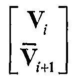
- V. and V. +1 are independent identically distributed (i.i.d.) Gaussian random vectors.
- receiver includes additional outputs from decoder/equalizer block 410 which each provide the appropriate inversion and complex conjugation functions based upon the number of transmit antennas at the transmitter.
- Fig. 5 The functionality described with respect to Fig. 5 may be implemented in receive processor 142 and processor 130 and receive processor 160 and processor 170. In such a case, the functionality described with respect to elements 404, 406, 408, 410, and 412 may provided in the processors.
- DSP digital signal processor
- ASIC application specific integrated circuit
- FPGA field programmable gate array
- a general purpose processor may be a microprocessor, but in the alternative, the processor may be any conventional processor, processor, microprocessor, or state machine.
- a processor may also be implemented as a combination of devices, e.g., a combination of a DSP and a microprocessor, a plurality of microprocessors, one or more microprocessors in conjunction with a DSP core, multiple logic elements, multiple circuits, or any other such configuration.
- a software module may reside in RAM memory, flash memory, ROM memory, EPROM memory, EEPROM memory, registers, hard disk, a removable disk, a CD-ROM, or any other form of storage medium known in the art.
- An exemplary storage medium is coupled to the processor such the processor can read information from, and write information to, the storage medium.
- the storage medium may be integral to the processor.
- the processor and the storage medium may reside in an ASIC.
- the ASIC may reside in a user terminal.
- the processor and the storage medium may reside as discrete components in a user terminal.
Landscapes
- Engineering & Computer Science (AREA)
- Computer Networks & Wireless Communication (AREA)
- Signal Processing (AREA)
- Physics & Mathematics (AREA)
- Discrete Mathematics (AREA)
- General Physics & Mathematics (AREA)
- Mathematical Physics (AREA)
- Radio Transmission System (AREA)
- Mobile Radio Communication Systems (AREA)
- Reduction Or Emphasis Of Bandwidth Of Signals (AREA)
- Compression, Expansion, Code Conversion, And Decoders (AREA)
Abstract
Description


Claims


Priority Applications (10)
| Application Number | Priority Date | Filing Date | Title |
|---|---|---|---|
| MXPA06014848A MXPA06014848A (en) | 2004-05-17 | 2005-04-29 | Space-time block coding in orthogonal frequency division communication systems. |
| DE602005019040T DE602005019040D1 (en) | 2004-05-17 | 2005-04-29 | SPACE-TIME BLOCK CODING IN ORTHOGONAL FREQUENCY MULTIPLEX COMMUNICATION SYSTEMS |
| CN2005800241577A CN101027866B (en) | 2004-05-17 | 2005-04-29 | Space-time block coding in orthogonal frequency division communication systems |
| EP05758402A EP1747632B1 (en) | 2004-05-17 | 2005-04-29 | Space-time block coding in orthogonal frequency division communication systems |
| CA002566700A CA2566700A1 (en) | 2004-05-17 | 2005-04-29 | Space-time block coding in orthogonal frequency division communication systems |
| BRPI0511145-5A BRPI0511145A (en) | 2004-05-17 | 2005-04-29 | spacetime block coding in orthogonal frequency division communication systems |
| AU2005330573A AU2005330573B8 (en) | 2004-05-17 | 2005-04-29 | Space-time block coding in orthogonal frequency division communication systems |
| JP2007527256A JP2007538464A (en) | 2004-05-17 | 2005-04-29 | Space-time block coding in orthogonal frequency division communication systems |
| AT05758402T ATE456207T1 (en) | 2004-05-17 | 2005-04-29 | SPACE-TIME BLOCK CODING IN ORTHOGONAL FREQUENCY MULTIPLEX COMMUNICATION SYSTEMS |
| IL179174A IL179174A0 (en) | 2004-05-17 | 2006-11-09 | Space-time block coding in orthogonal frequency division communication systems |
Applications Claiming Priority (4)
| Application Number | Priority Date | Filing Date | Title |
|---|---|---|---|
| US57216004P | 2004-05-17 | 2004-05-17 | |
| US60/572,160 | 2004-05-17 | ||
| US11/111,049 US7724835B2 (en) | 2004-05-17 | 2005-04-20 | Space-time block coding in orthogonal frequency division communication systems |
| US11/111,049 | 2005-04-20 |
Publications (1)
| Publication Number | Publication Date |
|---|---|
| WO2005117320A1 true WO2005117320A1 (en) | 2005-12-08 |
Family
ID=34972203
Family Applications (1)
| Application Number | Title | Priority Date | Filing Date |
|---|---|---|---|
| PCT/US2005/014852 Ceased WO2005117320A1 (en) | 2004-05-17 | 2005-04-29 | Space-time block coding in orthogonal frequency division communication systems |
Country Status (13)
| Country | Link |
|---|---|
| US (1) | US7724835B2 (en) |
| EP (1) | EP1747632B1 (en) |
| JP (1) | JP2007538464A (en) |
| KR (1) | KR100906285B1 (en) |
| CN (1) | CN101027866B (en) |
| AT (1) | ATE456207T1 (en) |
| BR (1) | BRPI0511145A (en) |
| CA (1) | CA2566700A1 (en) |
| DE (1) | DE602005019040D1 (en) |
| IL (1) | IL179174A0 (en) |
| MX (1) | MXPA06014848A (en) |
| RU (1) | RU2344555C2 (en) |
| WO (1) | WO2005117320A1 (en) |
Cited By (1)
| Publication number | Priority date | Publication date | Assignee | Title |
|---|---|---|---|---|
| JP2010511327A (en) * | 2006-11-28 | 2010-04-08 | 株式会社エヌ・ティ・ティ・ドコモ | Method and apparatus for broadband transmission from multiple non-colocated base stations over a wireless radio network |
Families Citing this family (30)
| Publication number | Priority date | Publication date | Assignee | Title |
|---|---|---|---|---|
| US7505529B2 (en) * | 2004-08-12 | 2009-03-17 | Interdigital Technology Corporation | Method and apparatus for implementing space frequency block coding in an orthogonal frequency division multiplexing wireless communication system |
| US8842693B2 (en) * | 2005-05-31 | 2014-09-23 | Qualcomm Incorporated | Rank step-down for MIMO SCW design employing HARQ |
| US8126066B2 (en) * | 2005-06-09 | 2012-02-28 | Telefonaktiebolaget Lm Ericsson (Publ) | Time and frequency channel estimation |
| AU2006203698A1 (en) * | 2005-08-26 | 2007-03-15 | Nec Australia Pty Ltd | Transmit diversity scheme |
| US8107543B2 (en) * | 2006-06-27 | 2012-01-31 | Amimon Ltd. | High diversity time-space coding and decoding for MIMO systems |
| WO2008066349A1 (en) * | 2006-12-01 | 2008-06-05 | Electronics And Telecommunications Research Institute | Method and apparatus for transmitting/receiving multiple codewords in sc-fdma system |
| KR100874264B1 (en) * | 2006-12-01 | 2008-12-16 | 한국전자통신연구원 | Method and apparatus for multiple code word transmission / reception in SC-FDMA system |
| CN101663873B (en) * | 2007-02-23 | 2013-07-24 | 日本放送协会 | Digital data transmitting device and digital data receiving device |
| US20080238621A1 (en) * | 2007-03-30 | 2008-10-02 | Broadcom Corporation | Multi-mode rfid reader architecture |
| US8498350B2 (en) * | 2009-04-17 | 2013-07-30 | Raytheon Company | Communication system incorporating physical layer waveform structure |
| WO2010121254A1 (en) * | 2009-04-17 | 2010-10-21 | Raytheon Company | Distributed maximal ratio combining receiver architecture |
| JP5702387B2 (en) * | 2009-09-21 | 2015-04-15 | アップル インコーポレイテッド | Signaling and channel estimation for uplink transmit diversity |
| US10050680B2 (en) * | 2010-06-07 | 2018-08-14 | Entropic Communications, Llc | Method and apparatus for real time multiplexing with transmitter and antenna array elements |
| US8837652B2 (en) | 2010-12-31 | 2014-09-16 | Raytheon Company | Receiver synchronization in radio communication systems employing transmit diversity |
| US8565336B2 (en) * | 2011-02-08 | 2013-10-22 | Electronics And Telecommunications Research Institute | Data transmission apparatus and method, and data reconstitution apparatus and method |
| KR101470592B1 (en) * | 2011-02-08 | 2014-12-10 | 한국전자통신연구원 | Data transmission apparatus and data transmission method for inserting of additional data at data modulation, and data reconstitution apparatus and data reconstitution method for separately processing data |
| FR2985134A1 (en) * | 2011-12-23 | 2013-06-28 | France Telecom | METHOD FOR TRANSMITTING AT LEAST ONE MULTI-CARRIER SIGNAL FORM OF OFDM-OQAM SYMBOLS |
| FR2985152A1 (en) | 2011-12-23 | 2013-06-28 | France Telecom | METHOD FOR GROUPING TRANSCEIVER-RECEIVER COUPLES TO COMMUNICATE ON A COMMUNICATIONS NETWORK |
| HK1210883A1 (en) * | 2012-06-25 | 2016-05-06 | 科希尔技术股份有限公司 | Modulation and equalization in an orthonormal time-frequency shifting communications system |
| EP2984801A1 (en) * | 2013-04-09 | 2016-02-17 | Interdigital Patent Holdings, Inc. | Joint precoding and multivariate backhaul compression for the downlink of cloud radio access networks |
| US10103792B2 (en) * | 2016-01-14 | 2018-10-16 | Intel Corporation | Apparatus, system and method of communicating a multiple-input-multiple-output (MIMO) transmission |
| EP3206353B1 (en) * | 2016-02-09 | 2020-02-05 | Technische Universität München | Filter banks and methods for operating filter banks |
| US9848342B1 (en) * | 2016-07-20 | 2017-12-19 | Ccip, Llc | Excursion compensation in multipath communication systems having performance requirements parameters |
| WO2018017302A1 (en) * | 2016-07-20 | 2018-01-25 | Intel IP Corporation | Apparatus, system and method of communicating a single carrier (sc) multiple-input-multiple-output (mimo) transmission |
| US10027442B2 (en) * | 2016-07-20 | 2018-07-17 | Intel IP Corporation | Apparatus, system and method of communicating a single carrier (SC) space time block code (STBC) transmission |
| US10924218B2 (en) | 2016-07-20 | 2021-02-16 | Intel IP Corporation | Apparatus, system and method of communicating a single carrier (SC) transmission |
| CN110011948B (en) | 2018-01-05 | 2023-09-22 | 中兴通讯股份有限公司 | Data transmission method and device, storage medium, electronic device |
| WO2019134689A1 (en) * | 2018-01-05 | 2019-07-11 | 中兴通讯股份有限公司 | Data transmission method and device, storage medium, and electronic device |
| CN113055067B (en) * | 2019-12-27 | 2024-04-26 | 中兴通讯股份有限公司 | Downlink signal processing method, device and base station |
| CN113159264B (en) * | 2020-11-12 | 2022-06-21 | 江西理工大学 | Intrusion detection method, system, device and readable storage medium |
Citations (1)
| Publication number | Priority date | Publication date | Assignee | Title |
|---|---|---|---|---|
| US20040022183A1 (en) * | 2002-08-01 | 2004-02-05 | Li Kuo Hui | System and method for transmitting data in a multiple-branch transmitter-diversity orthogonal frequency-division multiplexing (OFDM) system |
Family Cites Families (18)
| Publication number | Priority date | Publication date | Assignee | Title |
|---|---|---|---|---|
| JPH08321785A (en) * | 1995-05-24 | 1996-12-03 | Sony Corp | Transmitter, receiver, transmitting method, receiving method and transmitting method |
| JP3614436B2 (en) * | 1995-07-13 | 2005-01-26 | スタンフォード・テレコミュニケーションズ・インコーポレーテッド | Anti-multipath orthogonal code division multiple access system |
| US6134215A (en) * | 1996-04-02 | 2000-10-17 | Qualcomm Incorpoated | Using orthogonal waveforms to enable multiple transmitters to share a single CDM channel |
| US6006075A (en) * | 1996-06-18 | 1999-12-21 | Telefonaktiebolaget L M Ericsson (Publ) | Method and apparatus for transmitting communication signals using transmission space diversity and frequency diversity |
| US6256290B1 (en) * | 1996-09-13 | 2001-07-03 | Lucent Technologies, Inc. | Multi-carrier CDMA transmission system with frequency and transmit diversity |
| RU2145152C1 (en) * | 1998-10-08 | 2000-01-27 | Гармонов Александр Васильевич | Method for orthogonal distributed transmission- reception of signal in cellular communication network using code channel division |
| US6317411B1 (en) * | 1999-02-22 | 2001-11-13 | Motorola, Inc. | Method and system for transmitting and receiving signals transmitted from an antenna array with transmit diversity techniques |
| US6542556B1 (en) * | 2000-03-31 | 2003-04-01 | Nokia Mobile Phones Ltd. | Space-time code for multiple antenna transmission |
| US7272192B2 (en) * | 2000-04-14 | 2007-09-18 | Board Of Trustees Of The Leland Stanford Junior University | Time-reversal block transmit diversity system for channels with intersymbol interference and method |
| US7020072B1 (en) * | 2000-05-09 | 2006-03-28 | Lucent Technologies, Inc. | Orthogonal frequency division multiplexing transmit diversity system for frequency-selective fading channels |
| JP2002064461A (en) * | 2000-08-18 | 2002-02-28 | Mitsubishi Electric Corp | Communication device and communication method |
| US7061854B2 (en) * | 2001-10-15 | 2006-06-13 | Nortel Networks Limited | Efficient OFDM communications with interference immunity |
| WO2003043245A1 (en) * | 2001-11-10 | 2003-05-22 | Samsung Electronics Co., Ltd. | Stfbc coding/decoding apparatus and method in an ofdm mobile communication system |
| DE60332893D1 (en) * | 2002-04-25 | 2010-07-22 | Imec | CDMA Reception Transmission Techniques for Radio Systems with Multiple Inputs and Multiple Outputs (MIMO) |
| US7542446B2 (en) * | 2002-07-31 | 2009-06-02 | Mitsubishi Electric Research Laboratories, Inc. | Space time transmit diversity with subgroup rate control and subgroup antenna selection in multi-input multi-output communications systems |
| JP3677492B2 (en) * | 2002-07-31 | 2005-08-03 | 松下電器産業株式会社 | Multicarrier transmission apparatus and multicarrier transmission method |
| US7324605B2 (en) * | 2004-01-12 | 2008-01-29 | Intel Corporation | High-throughput multicarrier communication systems and methods for exchanging channel state information |
| US7746886B2 (en) * | 2004-02-19 | 2010-06-29 | Broadcom Corporation | Asymmetrical MIMO wireless communications |
-
2005
- 2005-04-20 US US11/111,049 patent/US7724835B2/en active Active
- 2005-04-29 KR KR1020067026691A patent/KR100906285B1/en not_active Expired - Fee Related
- 2005-04-29 MX MXPA06014848A patent/MXPA06014848A/en active IP Right Grant
- 2005-04-29 CA CA002566700A patent/CA2566700A1/en not_active Abandoned
- 2005-04-29 AT AT05758402T patent/ATE456207T1/en not_active IP Right Cessation
- 2005-04-29 JP JP2007527256A patent/JP2007538464A/en not_active Ceased
- 2005-04-29 EP EP05758402A patent/EP1747632B1/en not_active Expired - Lifetime
- 2005-04-29 BR BRPI0511145-5A patent/BRPI0511145A/en not_active IP Right Cessation
- 2005-04-29 DE DE602005019040T patent/DE602005019040D1/en not_active Expired - Lifetime
- 2005-04-29 CN CN2005800241577A patent/CN101027866B/en not_active Expired - Fee Related
- 2005-04-29 RU RU2006144834/09A patent/RU2344555C2/en not_active IP Right Cessation
- 2005-04-29 WO PCT/US2005/014852 patent/WO2005117320A1/en not_active Ceased
-
2006
- 2006-11-09 IL IL179174A patent/IL179174A0/en unknown
Patent Citations (1)
| Publication number | Priority date | Publication date | Assignee | Title |
|---|---|---|---|---|
| US20040022183A1 (en) * | 2002-08-01 | 2004-02-05 | Li Kuo Hui | System and method for transmitting data in a multiple-branch transmitter-diversity orthogonal frequency-division multiplexing (OFDM) system |
Non-Patent Citations (3)
| Title |
|---|
| AL-DHABIR N ET AL: "Three space-time block-coding schemes for frequency-selective fading cliannels with application to EDGE", VTC FALL 2001. IEEE 54TH. VEHICULAR TECHNOLOGY CONFERENCE. PROCEEDINGS. ATLANTIC CITY, NJ, OCT. 7 - 11, 2001, IEEE VEHICULAR TECHNOLGY CONFERENCE, NEW YORK, NY : IEEE, US, vol. VOL. 1 OF 4. CONF. 54, 7 October 2001 (2001-10-07), pages 1834 - 1838, XP010562281, ISBN: 0-7803-7005-8 * |
| STAMOULIS A ET AL: "SPACE-TIME BLOCK-CODED OFDMA WITH LINEAR PRECODING FOR MULTIRATE SERVICES", IEEE TRANSACTIONS ON SIGNAL PROCESSING, IEEE, INC. NEW YORK, US, vol. 50, no. 1, January 2002 (2002-01-01), pages 119 - 129, XP001200909, ISSN: 1053-587X * |
| UYSAL M ET AL: "A SPACE-TIME BLOCK-CODED OFDM SCHEME FOR UNKNOWN FREQUENCY-SELECTIVE FADING CHANNELS", IEEE COMMUNICATIONS LETTERS, IEEE SERVICE CENTER, PISCATAWAY,US, US, vol. 5, no. 10, October 2001 (2001-10-01), pages 393 - 395, XP001110782, ISSN: 1089-7798 * |
Cited By (1)
| Publication number | Priority date | Publication date | Assignee | Title |
|---|---|---|---|---|
| JP2010511327A (en) * | 2006-11-28 | 2010-04-08 | 株式会社エヌ・ティ・ティ・ドコモ | Method and apparatus for broadband transmission from multiple non-colocated base stations over a wireless radio network |
Also Published As
| Publication number | Publication date |
|---|---|
| CA2566700A1 (en) | 2005-12-08 |
| RU2344555C2 (en) | 2009-01-20 |
| ATE456207T1 (en) | 2010-02-15 |
| DE602005019040D1 (en) | 2010-03-11 |
| CN101027866A (en) | 2007-08-29 |
| EP1747632B1 (en) | 2010-01-20 |
| EP1747632A1 (en) | 2007-01-31 |
| KR20070014204A (en) | 2007-01-31 |
| JP2007538464A (en) | 2007-12-27 |
| CN101027866B (en) | 2013-03-20 |
| RU2006144834A (en) | 2008-06-27 |
| KR100906285B1 (en) | 2009-07-06 |
| BRPI0511145A (en) | 2007-11-27 |
| IL179174A0 (en) | 2007-03-08 |
| MXPA06014848A (en) | 2007-03-26 |
| US7724835B2 (en) | 2010-05-25 |
| US20050254596A1 (en) | 2005-11-17 |
Similar Documents
| Publication | Publication Date | Title |
|---|---|---|
| EP1747632B1 (en) | Space-time block coding in orthogonal frequency division communication systems | |
| US9100076B2 (en) | Time varying delay diversity of OFDM | |
| KR100870557B1 (en) | Apparatus and method for space-time coded transmission in wireless communication network | |
| Zhou et al. | Single-carrier space-time block-coded transmissions over frequency-selective fading channels | |
| US20060146692A1 (en) | Methods and apparatus for mitigating multi-antenna correlation effect in communication systems | |
| US20030112901A1 (en) | Method and apparatus for determining the log-likelihood ratio with precoding | |
| WO2006014143A1 (en) | Method for transmitting a digital data stream, transmitter, method for receiving a digital data stream and receiver | |
| EP1782553B1 (en) | Apparatus and method for obtaining delay diversity | |
| CN1989722B (en) | Time varying cyclic delay diversity of OFDM | |
| Lu et al. | A novel CDD-OFDM scheme with pilot-aided channel estimation | |
| EP1782565B1 (en) | Apparatus and method for obtaining cyclic delay diversity | |
| AU2005330573B8 (en) | Space-time block coding in orthogonal frequency division communication systems | |
| HK1106091A (en) | Space-time block coding in orthogonal frequency division communication systems | |
| HK1105728A (en) | Time varying cyclic delay diversity of ofdm |
Legal Events
| Date | Code | Title | Description |
|---|---|---|---|
| AK | Designated states |
Kind code of ref document: A1 Designated state(s): AE AG AL AM AT AU AZ BA BB BG BR BW BY BZ CA CH CN CO CR CU CZ DE DK DM DZ EC EE EG ES FI GB GD GE GH GM HR HU ID IL IN IS JP KE KG KM KP KR KZ LC LK LR LS LT LU LV MA MD MG MK MN MW MX MZ NA NI NO NZ OM PG PH PL PT RO RU SC SD SE SG SK SL SM SY TJ TM TN TR TT TZ UA UG US UZ VC VN YU ZA ZM ZW |
|
| AL | Designated countries for regional patents |
Kind code of ref document: A1 Designated state(s): GM KE LS MW MZ NA SD SL SZ TZ UG ZM ZW AM AZ BY KG KZ MD RU TJ TM AT BE BG CH CY CZ DE DK EE ES FI FR GB GR HU IE IS IT LT LU MC NL PL PT RO SE SI SK TR BF BJ CF CG CI CM GA GN GQ GW ML MR NE SN TD TG |
|
| 121 | Ep: the epo has been informed by wipo that ep was designated in this application | ||
| DPEN | Request for preliminary examination filed prior to expiration of 19th month from priority date (pct application filed from 20040101) | ||
| WWE | Wipo information: entry into national phase |
Ref document number: 179174 Country of ref document: IL |
|
| WWE | Wipo information: entry into national phase |
Ref document number: 2566700 Country of ref document: CA |
|
| WWE | Wipo information: entry into national phase |
Ref document number: 6703/DELNP/2006 Country of ref document: IN |
|
| WWE | Wipo information: entry into national phase |
Ref document number: 2005330573 Country of ref document: AU |
|
| WWE | Wipo information: entry into national phase |
Ref document number: 2007527256 Country of ref document: JP Ref document number: 12006502285 Country of ref document: PH |
|
| NENP | Non-entry into the national phase |
Ref country code: DE |
|
| WWW | Wipo information: withdrawn in national office |
Ref document number: DE |
|
| WWE | Wipo information: entry into national phase |
Ref document number: 2005758402 Country of ref document: EP |
|
| ENP | Entry into the national phase |
Ref document number: 2005330573 Country of ref document: AU Date of ref document: 20050429 Kind code of ref document: A |
|
| WWP | Wipo information: published in national office |
Ref document number: 2005330573 Country of ref document: AU |
|
| WWE | Wipo information: entry into national phase |
Ref document number: PA/a/2006/014848 Country of ref document: MX |
|
| WWE | Wipo information: entry into national phase |
Ref document number: 2006144834 Country of ref document: RU Ref document number: 1020067026691 Country of ref document: KR Ref document number: 1200602074 Country of ref document: VN |
|
| WWE | Wipo information: entry into national phase |
Ref document number: 200580024157.7 Country of ref document: CN |
|
| WWP | Wipo information: published in national office |
Ref document number: 2005758402 Country of ref document: EP Ref document number: 1020067026691 Country of ref document: KR |
|
| ENP | Entry into the national phase |
Ref document number: PI0511145 Country of ref document: BR |
|
| DPE2 | Request for preliminary examination filed before expiration of 19th month from priority date (pct application filed from 20040101) |