WO2006030795A1 - 圧延ロール用遠心鋳造外層及びその製造方法 - Google Patents
圧延ロール用遠心鋳造外層及びその製造方法 Download PDFInfo
- Publication number
- WO2006030795A1 WO2006030795A1 PCT/JP2005/016859 JP2005016859W WO2006030795A1 WO 2006030795 A1 WO2006030795 A1 WO 2006030795A1 JP 2005016859 W JP2005016859 W JP 2005016859W WO 2006030795 A1 WO2006030795 A1 WO 2006030795A1
- Authority
- WO
- WIPO (PCT)
- Prior art keywords
- outer layer
- carbide
- centrifugally
- rolling
- roll
- Prior art date
- Legal status (The legal status is an assumption and is not a legal conclusion. Google has not performed a legal analysis and makes no representation as to the accuracy of the status listed.)
- Ceased
Links
Classifications
-
- B—PERFORMING OPERATIONS; TRANSPORTING
- B22—CASTING; POWDER METALLURGY
- B22D—CASTING OF METALS; CASTING OF OTHER SUBSTANCES BY THE SAME PROCESSES OR DEVICES
- B22D13/00—Centrifugal casting; Casting by using centrifugal force
- B22D13/02—Centrifugal casting; Casting by using centrifugal force of elongated solid or hollow bodies, e.g. pipes, in moulds rotating around their longitudinal axis
- B22D13/023—Centrifugal casting; Casting by using centrifugal force of elongated solid or hollow bodies, e.g. pipes, in moulds rotating around their longitudinal axis the longitudinal axis being horizontal
-
- C—CHEMISTRY; METALLURGY
- C22—METALLURGY; FERROUS OR NON-FERROUS ALLOYS; TREATMENT OF ALLOYS OR NON-FERROUS METALS
- C22C—ALLOYS
- C22C37/00—Cast-iron alloys
-
- B—PERFORMING OPERATIONS; TRANSPORTING
- B21—MECHANICAL METAL-WORKING WITHOUT ESSENTIALLY REMOVING MATERIAL; PUNCHING METAL
- B21B—ROLLING OF METAL
- B21B27/00—Rolls, roll alloys or roll fabrication; Lubricating, cooling or heating rolls while in use
-
- B—PERFORMING OPERATIONS; TRANSPORTING
- B21—MECHANICAL METAL-WORKING WITHOUT ESSENTIALLY REMOVING MATERIAL; PUNCHING METAL
- B21B—ROLLING OF METAL
- B21B27/00—Rolls, roll alloys or roll fabrication; Lubricating, cooling or heating rolls while in use
- B21B27/02—Shape or construction of rolls
-
- B—PERFORMING OPERATIONS; TRANSPORTING
- B22—CASTING; POWDER METALLURGY
- B22D—CASTING OF METALS; CASTING OF OTHER SUBSTANCES BY THE SAME PROCESSES OR DEVICES
- B22D13/00—Centrifugal casting; Casting by using centrifugal force
- B22D13/02—Centrifugal casting; Casting by using centrifugal force of elongated solid or hollow bodies, e.g. pipes, in moulds rotating around their longitudinal axis
-
- B—PERFORMING OPERATIONS; TRANSPORTING
- B22—CASTING; POWDER METALLURGY
- B22D—CASTING OF METALS; CASTING OF OTHER SUBSTANCES BY THE SAME PROCESSES OR DEVICES
- B22D19/00—Casting in, on, or around objects which form part of the product
- B22D19/16—Casting in, on, or around objects which form part of the product for making compound objects cast of two or more different metals, e.g. for making rolls for rolling mills
-
- B—PERFORMING OPERATIONS; TRANSPORTING
- B32—LAYERED PRODUCTS
- B32B—LAYERED PRODUCTS, i.e. PRODUCTS BUILT-UP OF STRATA OF FLAT OR NON-FLAT, e.g. CELLULAR OR HONEYCOMB, FORM
- B32B15/00—Layered products comprising a layer of metal
- B32B15/01—Layered products comprising a layer of metal all layers being exclusively metallic
- B32B15/011—Layered products comprising a layer of metal all layers being exclusively metallic all layers being formed of iron alloys or steels
-
- C—CHEMISTRY; METALLURGY
- C21—METALLURGY OF IRON
- C21D—MODIFYING THE PHYSICAL STRUCTURE OF FERROUS METALS; GENERAL DEVICES FOR HEAT TREATMENT OF FERROUS OR NON-FERROUS METALS OR ALLOYS; MAKING METAL MALLEABLE, e.g. BY DECARBURISATION OR TEMPERING
- C21D9/00—Heat treatment, e.g. annealing, hardening, quenching or tempering, adapted for particular articles; Furnaces therefor
- C21D9/36—Heat treatment, e.g. annealing, hardening, quenching or tempering, adapted for particular articles; Furnaces therefor for balls; for rollers
-
- C—CHEMISTRY; METALLURGY
- C21—METALLURGY OF IRON
- C21D—MODIFYING THE PHYSICAL STRUCTURE OF FERROUS METALS; GENERAL DEVICES FOR HEAT TREATMENT OF FERROUS OR NON-FERROUS METALS OR ALLOYS; MAKING METAL MALLEABLE, e.g. BY DECARBURISATION OR TEMPERING
- C21D9/00—Heat treatment, e.g. annealing, hardening, quenching or tempering, adapted for particular articles; Furnaces therefor
- C21D9/38—Heat treatment, e.g. annealing, hardening, quenching or tempering, adapted for particular articles; Furnaces therefor for roll bodies
-
- C—CHEMISTRY; METALLURGY
- C22—METALLURGY; FERROUS OR NON-FERROUS ALLOYS; TREATMENT OF ALLOYS OR NON-FERROUS METALS
- C22C—ALLOYS
- C22C38/00—Ferrous alloys, e.g. steel alloys
- C22C38/02—Ferrous alloys, e.g. steel alloys containing silicon
-
- C—CHEMISTRY; METALLURGY
- C22—METALLURGY; FERROUS OR NON-FERROUS ALLOYS; TREATMENT OF ALLOYS OR NON-FERROUS METALS
- C22C—ALLOYS
- C22C38/00—Ferrous alloys, e.g. steel alloys
- C22C38/04—Ferrous alloys, e.g. steel alloys containing manganese
-
- C—CHEMISTRY; METALLURGY
- C22—METALLURGY; FERROUS OR NON-FERROUS ALLOYS; TREATMENT OF ALLOYS OR NON-FERROUS METALS
- C22C—ALLOYS
- C22C38/00—Ferrous alloys, e.g. steel alloys
- C22C38/18—Ferrous alloys, e.g. steel alloys containing chromium
- C22C38/22—Ferrous alloys, e.g. steel alloys containing chromium with molybdenum or tungsten
-
- C—CHEMISTRY; METALLURGY
- C22—METALLURGY; FERROUS OR NON-FERROUS ALLOYS; TREATMENT OF ALLOYS OR NON-FERROUS METALS
- C22C—ALLOYS
- C22C38/00—Ferrous alloys, e.g. steel alloys
- C22C38/18—Ferrous alloys, e.g. steel alloys containing chromium
- C22C38/24—Ferrous alloys, e.g. steel alloys containing chromium with vanadium
-
- C—CHEMISTRY; METALLURGY
- C22—METALLURGY; FERROUS OR NON-FERROUS ALLOYS; TREATMENT OF ALLOYS OR NON-FERROUS METALS
- C22C—ALLOYS
- C22C38/00—Ferrous alloys, e.g. steel alloys
- C22C38/18—Ferrous alloys, e.g. steel alloys containing chromium
- C22C38/26—Ferrous alloys, e.g. steel alloys containing chromium with niobium or tantalum
-
- C—CHEMISTRY; METALLURGY
- C22—METALLURGY; FERROUS OR NON-FERROUS ALLOYS; TREATMENT OF ALLOYS OR NON-FERROUS METALS
- C22C—ALLOYS
- C22C38/00—Ferrous alloys, e.g. steel alloys
- C22C38/18—Ferrous alloys, e.g. steel alloys containing chromium
- C22C38/30—Ferrous alloys, e.g. steel alloys containing chromium with cobalt
-
- C—CHEMISTRY; METALLURGY
- C22—METALLURGY; FERROUS OR NON-FERROUS ALLOYS; TREATMENT OF ALLOYS OR NON-FERROUS METALS
- C22C—ALLOYS
- C22C38/00—Ferrous alloys, e.g. steel alloys
- C22C38/18—Ferrous alloys, e.g. steel alloys containing chromium
- C22C38/36—Ferrous alloys, e.g. steel alloys containing chromium with more than 1.7% by weight of carbon
-
- C—CHEMISTRY; METALLURGY
- C22—METALLURGY; FERROUS OR NON-FERROUS ALLOYS; TREATMENT OF ALLOYS OR NON-FERROUS METALS
- C22C—ALLOYS
- C22C38/00—Ferrous alloys, e.g. steel alloys
- C22C38/18—Ferrous alloys, e.g. steel alloys containing chromium
- C22C38/40—Ferrous alloys, e.g. steel alloys containing chromium with nickel
- C22C38/44—Ferrous alloys, e.g. steel alloys containing chromium with nickel with molybdenum or tungsten
-
- C—CHEMISTRY; METALLURGY
- C22—METALLURGY; FERROUS OR NON-FERROUS ALLOYS; TREATMENT OF ALLOYS OR NON-FERROUS METALS
- C22C—ALLOYS
- C22C38/00—Ferrous alloys, e.g. steel alloys
- C22C38/18—Ferrous alloys, e.g. steel alloys containing chromium
- C22C38/40—Ferrous alloys, e.g. steel alloys containing chromium with nickel
- C22C38/46—Ferrous alloys, e.g. steel alloys containing chromium with nickel with vanadium
-
- C—CHEMISTRY; METALLURGY
- C22—METALLURGY; FERROUS OR NON-FERROUS ALLOYS; TREATMENT OF ALLOYS OR NON-FERROUS METALS
- C22C—ALLOYS
- C22C38/00—Ferrous alloys, e.g. steel alloys
- C22C38/18—Ferrous alloys, e.g. steel alloys containing chromium
- C22C38/40—Ferrous alloys, e.g. steel alloys containing chromium with nickel
- C22C38/48—Ferrous alloys, e.g. steel alloys containing chromium with nickel with niobium or tantalum
-
- C—CHEMISTRY; METALLURGY
- C22—METALLURGY; FERROUS OR NON-FERROUS ALLOYS; TREATMENT OF ALLOYS OR NON-FERROUS METALS
- C22C—ALLOYS
- C22C38/00—Ferrous alloys, e.g. steel alloys
- C22C38/18—Ferrous alloys, e.g. steel alloys containing chromium
- C22C38/40—Ferrous alloys, e.g. steel alloys containing chromium with nickel
- C22C38/52—Ferrous alloys, e.g. steel alloys containing chromium with nickel with cobalt
-
- C—CHEMISTRY; METALLURGY
- C22—METALLURGY; FERROUS OR NON-FERROUS ALLOYS; TREATMENT OF ALLOYS OR NON-FERROUS METALS
- C22C—ALLOYS
- C22C38/00—Ferrous alloys, e.g. steel alloys
- C22C38/18—Ferrous alloys, e.g. steel alloys containing chromium
- C22C38/40—Ferrous alloys, e.g. steel alloys containing chromium with nickel
- C22C38/56—Ferrous alloys, e.g. steel alloys containing chromium with nickel with more than 1.7% by weight of carbon
-
- F—MECHANICAL ENGINEERING; LIGHTING; HEATING; WEAPONS; BLASTING
- F16—ENGINEERING ELEMENTS AND UNITS; GENERAL MEASURES FOR PRODUCING AND MAINTAINING EFFECTIVE FUNCTIONING OF MACHINES OR INSTALLATIONS; THERMAL INSULATION IN GENERAL
- F16C—SHAFTS; FLEXIBLE SHAFTS; ELEMENTS OR CRANKSHAFT MECHANISMS; ROTARY BODIES OTHER THAN GEARING ELEMENTS; BEARINGS
- F16C13/00—Rolls, drums, discs, or the like; Bearings or mountings therefor
-
- Y—GENERAL TAGGING OF NEW TECHNOLOGICAL DEVELOPMENTS; GENERAL TAGGING OF CROSS-SECTIONAL TECHNOLOGIES SPANNING OVER SEVERAL SECTIONS OF THE IPC; TECHNICAL SUBJECTS COVERED BY FORMER USPC CROSS-REFERENCE ART COLLECTIONS [XRACs] AND DIGESTS
- Y10—TECHNICAL SUBJECTS COVERED BY FORMER USPC
- Y10T—TECHNICAL SUBJECTS COVERED BY FORMER US CLASSIFICATION
- Y10T29/00—Metal working
- Y10T29/49—Method of mechanical manufacture
- Y10T29/49544—Roller making
- Y10T29/4956—Fabricating and shaping roller work contacting surface element
- Y10T29/49563—Fabricating and shaping roller work contacting surface element with coating or casting about a core
-
- Y—GENERAL TAGGING OF NEW TECHNOLOGICAL DEVELOPMENTS; GENERAL TAGGING OF CROSS-SECTIONAL TECHNOLOGIES SPANNING OVER SEVERAL SECTIONS OF THE IPC; TECHNICAL SUBJECTS COVERED BY FORMER USPC CROSS-REFERENCE ART COLLECTIONS [XRACs] AND DIGESTS
- Y10—TECHNICAL SUBJECTS COVERED BY FORMER USPC
- Y10T—TECHNICAL SUBJECTS COVERED BY FORMER US CLASSIFICATION
- Y10T29/00—Metal working
- Y10T29/49—Method of mechanical manufacture
- Y10T29/4998—Combined manufacture including applying or shaping of fluent material
- Y10T29/49988—Metal casting
- Y10T29/49989—Followed by cutting or removing material
-
- Y—GENERAL TAGGING OF NEW TECHNOLOGICAL DEVELOPMENTS; GENERAL TAGGING OF CROSS-SECTIONAL TECHNOLOGIES SPANNING OVER SEVERAL SECTIONS OF THE IPC; TECHNICAL SUBJECTS COVERED BY FORMER USPC CROSS-REFERENCE ART COLLECTIONS [XRACs] AND DIGESTS
- Y10—TECHNICAL SUBJECTS COVERED BY FORMER USPC
- Y10T—TECHNICAL SUBJECTS COVERED BY FORMER US CLASSIFICATION
- Y10T428/00—Stock material or miscellaneous articles
- Y10T428/12—All metal or with adjacent metals
- Y10T428/12493—Composite; i.e., plural, adjacent, spatially distinct metal components [e.g., layers, joint, etc.]
- Y10T428/12771—Transition metal-base component
- Y10T428/12806—Refractory [Group IVB, VB, or VIB] metal-base component
- Y10T428/12812—Diverse refractory group metal-base components: alternative to or next to each other
Definitions
- the present invention relates to a centrifugally-rolled outer layer for a rolling roll that is excellent in wear resistance, rough skin resistance, seizure resistance, and the like, and particularly suitable for a work roll in a finishing row of a hot sheet rolling mill, and a method for producing the same. .
- Wear resistance and rough skin resistance of rolling rolls are important characteristics that determine the productivity of rolling. If the wear resistance is poor, the roll surface will be worn out early and the dimensional accuracy of the material to be rolled will be impaired. Also, if the surface of the rolling roll is worn unevenly due to contact with the material to be rolled or contact with the backup roll, and rough skin occurs, the rough surface is transferred to the rolled material, and the surface of the rolled material is removed. The appearance is damaged. In order to prevent these problems, the rolls must be replaced frequently, resulting in a decrease in rolling mill productivity due to the increased frequency of rolling operation interruptions, an increase in the cost required for roll surface grinding, and roll surface grinding. Problems such as a reduction in the basic unit of roll due to an increase in amount occur.
- the seizure resistance of the rolling roll is also important. Due to the poor seizure resistance and the heat generated in the roll byte during rolling, the material to be rolled is seized on the roll, and normal rolling cannot be performed. In particular, in the latter stage stand of the finishing row of a hot sheet rolling mill, an accident called so-called “drawing” occurs in which the end of the material to be rolled is rolled by two sheets for some reason. At that time, if the seizure resistance is poor, the material to be rolled is baked on the roll, and further, the material to be rolled gets stuck on the roll body and is forced to stop rolling. In addition, when the material to be rolled is rolled while being baked on the roll, a crack is generated due to the concentration of the rolling load on the baked portion, and the roll such as a spall may be damaged starting from the crack.
- High-speed roll materials contain high-hardness carbides (MC, M C, M C M C, etc.) made of alloy elements.
- alloying elements especially V
- Nb forms extremely hard MC carbide with a Vickers hardness of about Hv 2400-3200 and contributes significantly to the improvement of wear resistance.
- centrifugal forging of molten metal containing a lot of V and Nb Then, MC carbide segregates to the inner surface side by centrifugation.
- This phenomenon is likely to occur when the molten metal is primary and crystallizes granular carbides. Since the primary crystal carbide is lighter than the molten metal (specific gravity: about 7-8 g / cm 3 ) with a specific gravity of about 3 ⁇ 4 g / cm 3, it moves to the inner surface by centrifugal force.
- JP-A-9-256108 describes C: 3.5 to 5.5%, Si: 0.1 to 1.5%, Mn: 0.1 to 1.2% Cr: 4.0 to 12.0%, Mo: 2.0 to 8.0%, V: 12.0 to 18.0%, the balance Fe and unavoidable impurities are proposed and a hot rolling tool steel is proposed! Since VC has a small specific gravity, it is prayed by centrifugal forging, but Nb forms a composite carbide (V, Nb) C with a large specific gravity with V, thus preventing segregation of carbides by centrifugation.
- Japanese Patent Laid-Open No. 3-254304 has a structure containing 5-30% granular carbide and 5% or less non-particulate carbide in area ratio, and the hardness of the base is 550 or more in terms of Vickers hardness Hv
- a composite roll for hot rolling having an outer layer is disclosed.
- Basic composition of the outer layer of the hot-rolling composite roll is 1.0 to 3.5 mass 0/0 C, 3.0 mass 0/0 less Si, 1.5 mass 0/0 Mn, up from 2 to 10 mass% Cr, 9 mass% or less Mo, 20 mass% or less W, 2 to 15 mass% V, the balance Fe, and impurities.
- this composite roll is formed by a so-called continuous build-up forging method in which an outer layer is continuously formed using a high-frequency coil around a core material made of steel.
- a problem that it is difficult to cope with the increase in the size of rolls.
- JP-A-7-268569 describes, by weight ratio, C: 1.8-5%, Si: 2% or less, Mn: 2% or less, Cr: 4-6%, W: 2-8%, Mo: 2-10%, V: more than 11% 17% or less, Co7-13%, balance Fe and inevitable impurities, MC carbide with average particle size 1-30111 and area ratio 20-40%
- a wear-resistant sintered alloy is disclosed.
- this alloy is formed by the HIP method.
- the manufacturing cost is higher than the centrifugal forging method and it is difficult to cope with the enlargement of the roll.
- JP-A-2000-303135 is a hot-rolling composite roll in which an outer layer and an inner layer are welded via an intermediate layer, wherein the outer layer is 1.5 to 2.6% by weight, Si: Containing 0.1 to 2.0%, Mn: 0.1 to 2.0%, Cr: 7 to 15%, Mo: 2.5 to 10%, V: 3 to 10%, Nb: 0.5 to 5%, the balance being Fe and unavoidable impurities has a composition, and discloses a hot composite roll for rolling average thermal expansion coefficient is less than 11.5 X 10- 6 Z ° C at room temperature ⁇ 300 ° C. In this composite roll, thermal expansion is suppressed by controlling the thermal expansion coefficient of the outer layer, but MC carbide such as VC prays inward in the outer-layer forged outer layer, so the surface wear resistance is always Not improved enough.
- an object of the present invention is to solve the problem of MC carbide prayer in the outer layer of the centrifugally-rolled roll, and to provide a centrifugally-rolled outer layer for a roll having excellent wear resistance, rough skin resistance, and seizure resistance, and its It is to provide a manufacturing method.
- MC carbide has higher thermal conductivity than Fe base (especially the thermal conductivity of VC is about 4 W / mK compared to 30-50 W / m'K for Fe base) It is very low) and is effective in reducing the thermal conductivity of the outer roll layer.
- the first centrifugally-rolled outer layer for rolling rolls of the present invention comprises, in mass%, C: 4.5 to 9%, Si: 0.1 to It contains 3.5%, Mn: 0.1 to 3.5%, V: 18 to 40%, and has a composition comprising the balance Fe and inevitable impurity elements.
- the first centrifugally-rolled outer layer for rolling rolls is further mass%, Cr: 1 to 15%, Mo: 0.5 to 10
- % And W It is preferable to contain at least one selected group power consisting of 1 to 40%.
- At least part of V is represented by the following formula (1):
- the first centrifugally-rolled outer layer for a rolling roll has the following formula (2):
- the first centrifugally-rolled outer layer for rolling rolls is further mass%, and Ni and Z or 10% or less.
- the first centrifugally-rolled outer layer for rolling rolls further has a mass% of 0.5% or less of cocoons and Z or
- the second centrifugally-rolled outer layer for rolling rolls of the present invention has a structure in which MC carbide is dispersed in an area ratio of 20 to 60% at a base having a Vickers hardness of Hv 550 to 900, It is characterized in that the maximum inscribed circle diameter of the region does not exceed 150 ⁇ m without including MC carbide with an equivalent diameter of 15 ⁇ m or more.
- the third centrifugally-rolled outer layer for rolling rolls of the present invention has a structure in which MC carbide is dispersed in an area ratio of 20 to 60% at a base having a Vickers hardness of Hv 550 to 900, The average distance between MC carbides with an equivalent diameter of 15 ⁇ m or more is 10 to 40 ⁇ m.
- the average equivalent circle diameter of MC carbide is preferably 10 to 50 ⁇ m.
- the ratio (B / A) between the average distance B between MC carbides having an equivalent circle diameter of 15 ⁇ m or more and the average equivalent circle diameter A of MC carbides is preferably 2 or less.
- MC, MC, and MC carbides having an area ratio of an equivalent circle diameter of 1 ⁇ m or more may be dispersed in a total amount of 0 to 5%.
- the second and third centrifugal roll outer layers for rolling rolls are in mass%, C: 2.5 to 9%, Si: 0.1 to
- It preferably has a composition containing 3.5%, Mn: 0.1 to 3.5%, and V: 11 to 40%, and the balance consisting of Fe and inevitable impurity elements.
- the second and third centrifugally-rolled outer layers for rolling rolls are further mass%, Cr: 1 to 15%, Mo:
- Group power consisting of 0.5 to 20% and W: 1 to 40% It is preferable to contain at least one selected.
- the second and third centrifugally-rolled outer layers for rolling rolls are further in% by mass of 2% or less Ni and
- the second and third centrifugally-rolled outer layers for rolling rolls preferably further contain, by mass, 0.5% or less of cocoons and Z or 0.5% or less of A1.
- the second and third mill roll centrifuge ⁇ outer layer is preferably not more than the average thermal bulging expansion coefficient is 10 X 10- 6 Z ° C at room temperature ⁇ 300 ° C.
- the thermal conductivity at 300 ° C is 25
- the longitudinal elastic modulus is 240 GPa or more.
- MC carbides area ratio to produce an outer layer for rolling rolls having a 20% to 60% dispersed tissue mass 0/0, C: 2.2 ⁇ 6.0% , Si: 0.1 ⁇ 3.5% , Mn: 0.1 to 3.5%, and V: 8 to 22%, and the inner peripheral layer in which MC carbides are concentrated by centrifugally forging a molten metal having a composition of balance Fe and inevitable impurity element power, MC carbide-deficient outer layer and an intermediate layer in which the area ratio of MC carbide varies between the inner and outer layers (layers with a gradient in MC carbide concentration are simply “concentration gradient layers”) And the cylindrical body is cut to a depth where the area ratio of MC carbide is 20% or more.
- the base of the outer layer for the rolling roll obtained by the method of the present invention preferably has a Vickers hardness Hv of 550 to 900. Further, MC, MC, and MC carbide having an area ratio of 1 ⁇ m or more in terms of area ratio may be dispersed in the outer layer structure in a total amount of 0 to 5%.
- the centrifugally formed outer layer for rolling rolls of the present invention is a work roll for rolling, particularly a work roll used in a finishing row of a hot sheet rolling mill, and has excellent wear resistance, rough skin resistance and seizure resistance. Demonstrate and contribute to the improvement of rolling productivity and the basic unit of roll.
- the method of the present invention is excellent in that MC carbide can be dispersed in a large amount and uniformly using the same centrifugal forging apparatus as in the conventional case where the molten metal temperature needs to be remarkably increased in order to increase the V content in the molten metal.
- FIG. 1 is a schematic view showing a method for determining the equivalent circle diameter of MC carbide.
- FIG. 2 is a schematic diagram showing a method for obtaining an average distance between MC carbides.
- FIG. 3 is a schematic diagram showing a method for obtaining the maximum inscribed circle diameter of a region not containing MC carbide.
- FIG. 4 (a) is a schematic diagram showing how MC carbide moves to the inner surface side during centrifugal forging.
- FIG. 4 (b) is a radial cross-sectional view showing a centrifugally-spun outer layer for a rolling roll according to the present invention.
- FIG. 4 (c) is a graph showing the distribution of MC carbide in the AA cross section of FIG. 4 (b).
- FIG. 5 is a graph showing the radial distribution of elements in the centrifugally fabricated cylindrical body of Example 4.
- FIG. 6 is a graph showing the radial distribution of MC carbide in the centrifugally fabricated cylindrical body of Example 4.
- FIG. 7 is a graph showing the radial distribution of elements in the centrifugally fabricated cylindrical body of Example 6.
- FIG. 8 is a graph showing the radial distribution of MC carbide in the centrifugally fabricated cylindrical body of Example 6.
- FIG. 9 is a graph showing the radial distribution of elements in the centrifugally fabricated cylindrical body of Conventional Example 2.
- FIG. 10 is a graph showing the radial distribution of MC carbide in the centrifugally fabricated cylindrical body of Conventional Example 2.
- FIG. 11 is a schematic view showing a rolling wear tester.
- FIG. 12 is a schematic view showing a seizure tester.
- FIG. 13 is an optical micrograph showing the metal structure of the test piece of Example 4.
- FIG. 14 is an optical micrograph showing the metal structure of the test piece of Comparative Example 1.
- FIG. 15 is an optical micrograph showing the metal structure of the test piece of Conventional Example 2.
- FIG. 16 is a graph showing the relationship between the value of (V% + 0.55 ⁇ Nb%) and the area ratio of MC carbide.
- FIG. 17 is a graph showing the relationship between the coefficient of thermal expansion and the temperature in the test pieces of Example 4, Comparative Example 1 and Conventional Example 2.
- FIG. 18 is a graph showing the relationship between thermal conductivity and temperature in the test pieces of Example 4, Comparative Example 1 and Conventional Example 2.
- C is an essential element that improves wear resistance mainly by bonding with alloy elements such as V and Nb to form MC carbide.
- C which does not bind to alloy elements, mainly dissolves in the matrix or precipitates very finely, strengthening the matrix. If C is less than 2.5%, the amount of MC carbide is insufficient and sufficient wear resistance cannot be obtained. On the other hand, if C exceeds 9%, the amount of carbide becomes excessive, and the heat crack resistance of the outer layer of the roll deteriorates.
- the C content is preferably 3.5 to 9%, more preferably 4.5 to 9%.
- Si acts as a deoxidizer in the molten metal. If Si is less than 0.1%, the deoxidation effect is insufficient and forged defects are likely to occur. On the other hand, when Si exceeds 3.5%, the outer layer of the roll becomes brittle.
- the Si content is preferably 0.2 to 2.5%, more preferably 0.2 to 1.5%.
- Mn has the effect of fixing deoxidation of molten metal and impurity S as MnS. If Mn is less than 0.1%, these effects are insufficient. On the other hand, if Mn exceeds 3.5%, retained austenite is likely to be generated, the hardness cannot be stably maintained, and the wear resistance is likely to deteriorate. Become.
- the Mn content is preferably 0.2 to 2.5%, more preferably 0.2 to 1.5%.
- V is an element that mainly bonds with C to form MC carbide. In order to include a large amount of MC carbide in the outer layer of the roll, 11-40% V is required. If V is less than 11%, MC carbide is insufficient and sufficient wear resistance cannot be obtained. On the other hand, if V exceeds 40%, MC carbide becomes excessive and the toughness of the outer roll layer deteriorates.
- the V content is preferably 15 to 40% or less, more preferably 18 to 40%.
- Nb has the same effect as V in forming MC carbide. From the atomic weight ratio, 0.55 X in mass% Therefore, the following equation (3):
- V may be replaced with an amount of Nb that satisfies the requirements!
- Nb an amount of Nb that satisfies the requirements!
- a more preferable range of (V% + 0.55 ⁇ Nb%) is 15% to 40% by mass%, and the most preferable range is 18% to 40%.
- Nb is C and V, and the following formula (2):
- the outer layer may appropriately contain the following elements.
- Cr dissolves in the matrix and improves hardenability, and part of it combines with C to precipitate as ultrafine carbide, strengthening the matrix. If Cr is less than 1%, the effect of strengthening the base cannot be obtained sufficiently. On the other hand, if Cr exceeds 15%, carbides other than MC carbide, such as MC carbide, are
- Mo dissolves in the base to improve hardenability, and a part of it combines with C to precipitate as ultrafine carbide, strengthening the base. Part of Mo forms granular carbides. If Mo is less than 0.5%, the effect of strengthening the base cannot be obtained sufficiently. On the other hand, when Mo exceeds 20%, non-particulate carbides such as M C and M C crystallize in a network, and the heat crack resistance of the outer layer of the roll deteriorates.
- the Mo content is more preferably 2.5 to 20%, particularly 2.5 to 10%.
- W forms a solid solution in the base to improve hardenability, and partly combines with C to deposit as ultrafine carbides, strengthening the base. Part of W forms granular carbides. If W is less than 1%, the effect of strengthening the base cannot be obtained sufficiently. On the other hand, if W exceeds 40%, M C, M C, etc.
- Non-particulate carbides crystallize in a network and heat crack resistance of the outer roll layer deteriorates.
- the w content is more preferably 5 to 40%, particularly 5 to 20%.
- Ni dissolves in the base and is effective in improving the hardenability of the base. If Ni exceeds 2%, the base austenite becomes stable and the hardening effect of the base is insufficient.
- Co dissolves in the base and has the effect of strengthening the base. If Co is contained, the hardness of the base can be maintained even at high temperatures. When Co exceeds 10%, the toughness of the outer layer of the roll decreases. Since Co is expensive, it is desirable to determine its content in consideration of economy and usage conditions.
- Ti In addition to acting as a deoxidizer in the molten metal, Ti combines with N to form nitrides, which serve as the core of granular carbides and have the effect of making the granular carbides fine. Some of them combine with C to form granular carbides. The effect of adding Ti is 0.5% or less.
- Al 0.5% or less In addition to acting as a deoxidizer in the molten metal, Al has the effect of making the particulate carbide fine. If A 1 exceeds 0.5%, the hardenability of the outer layer is deteriorated and sufficient base hardness cannot be obtained.
- MC carbide is a granular carbide compared to other carbides (M C, M C, M C carbide, etc.)
- MC carbide has high hardness and contributes to improvement of wear resistance.
- MC carbide is stable at high temperatures and is difficult to metal bond with the material to be rolled, so it has an excellent effect on improving seizure resistance. If the MC carbide is less than 20% in area ratio, the wear resistance, seizure resistance and heat crack resistance are insufficient. On the other hand, when MC carbide exceeds 60% in area ratio, the seizure resistance improving effect is saturated and the toughness of the outer roll layer is significantly reduced. In addition, cracks with a narrow interval between adjacent granular carbides are likely to propagate, and heat cracking resistance deteriorates. Therefore, MC carbide is 20-60% in area ratio. A preferred area ratio is 30 to 50%.
- the average equivalent circle diameter of MC carbide is preferably 10 to 50 m.
- the roll comes into contact with the hot rolled steel sheet and the base softens to about 10 m from the surface. Therefore, if the average equivalent diameter of MC carbide is less than 10 ⁇ m, the base can fully support the MC carbide. Furthermore, the roll has low wear resistance and rough skin resistance. On the other hand, if the average equivalent circle diameter exceeds 50 m, the effect of improving seizure resistance is saturated and the toughness decreases.
- the average equivalent circle diameter of the MC carbide is more preferably 10 to 40 / ⁇ ⁇ , and most preferably 15 to 30 ⁇ m.
- the average equivalent circle diameter of C carbide is the average value of D.
- the average distance between MC carbides having an equivalent circle diameter of 15 ⁇ m or more is preferably 10 to 40 ⁇ m.
- the average distance between MC carbides is less than 10 ⁇ m, the MC carbides are unevenly distributed, and microscopic unevenness due to wear difference occurs between the parts with a lot of MC carbides and the parts with little MC carbides, resulting in low resistance to rough skin.
- the average MC carbide distance is 40 If it exceeds / zm, no significant improvement in seizure resistance can be seen so that the dispersion of MC carbide distribution cannot be ignored.
- the average distance between MC carbides having an equivalent circle diameter of 15 ⁇ m or more is more preferably 20 to 30 ⁇ m.
- Fig. 2 schematically showing the structure of the outer layer of the roll.
- This structure contains MC carbide (white) la with an equivalent circle diameter of 15 m or more and MC carbide (black) lb with an equivalent circle diameter of less than 15 ⁇ m.
- 2 is the base (M C, M C and M
- the average distance between MC carbides with an equivalent circle diameter of 15 m or more is [ ⁇ (L + L +
- the ratio (B / A) between the average distance B between MC carbides having an equivalent circle diameter of 15 ⁇ m or more and the average equivalent circle diameter A of MC carbides is 2 or less. It is preferable.
- MC carbide tends to aggregate.
- the B / A ratio indicates the degree of aggregation of MC carbides.
- the B / A force exceeds 3 ⁇ 4, MC carbides are agglomerated too much.
- a more preferable B / A ratio is 1.5 or less.
- the maximum inscribed circle diameter of the region not containing MC carbide having an equivalent circle diameter of 15 ⁇ m or more does not exceed 150 / zm.
- the maximum inscribed circle diameter is more preferably 120 ⁇ m or less, and more preferably 80 ⁇ m or less.
- the diameter of the circle 20 inscribed in, la and la is D. In the same way, inscribed other MC carbide groups.
- the base is mainly composed of Fe and alloy elements, and the hardness changes due to transformation by heat treatment and precipitation of ultrafine carbides.
- the hardness of the base is Vickers hardness and less than Hv 550, the wear resistance of the outer layer of the roll is insufficient. From the viewpoint of improving wear resistance, it is desirable that the base is hard, but if it exceeds Hv 900, the toughness of the base decreases.
- a more preferable hardness of the base is Hv 650 to 850, and more preferably Hv 650 to 750.
- Roll outer layer of the present invention is the average thermal expansion coefficient of 10 X 10- 6 Z ° C hereinafter in room temperature ⁇ 300 ° C.
- MC carbide has a smaller coefficient of thermal expansion than other carbides, so it is effective in reducing the coefficient of thermal expansion of the outer layer.
- an average thermal expansion coefficient at room temperature ⁇ 300 ° C of VC is about 7 X 10- 6 Z ° C
- the Cr C is Cr carbide 10 X 10-
- a small average thermal expansion coefficient can suppress the growth of the thermal crown. However, if the thermal expansion coefficient of the outer layer is too small, the residual stress of the roll becomes excessive, and the risk of breakage and outer layer peeling increases.
- Average thermal expansion coefficient at room temperature ⁇ 300 ° C is more preferable properly not more than 9.5 X 10- 6 Z ° C, and most preferably 8 ⁇ 9.5 X 10- 6 Z ° C.
- the outer roll layer of the present invention preferably has a thermal conductivity at 300 ° C. of 25 W / m ′ K or less.
- the thermal conductivity of MC carbide is significantly lower than that of the Fe base.
- the thermal conductivity of VC is about 4 W / m 'K, much lower than about 30-50 W / m' K of the Fe base. Therefore, by dispersing MC carbide of 20-60% in area ratio in the metal structure, the temperature rise near the center in the axial direction of the roll and the inside thereof is reduced, and the growth of the thermal crown is suppressed. Can be improved.
- the thermal conductivity at 300 ° C is more preferably 23 W / m-K or less, and most preferably 21 W / m'K or less.
- Non-particulate carbide has a higher modulus of longitudinal elasticity than Fe, inclusion of a large amount of MC carbide increases the longitudinal modulus of elasticity of the outer layer of the roll.
- the longitudinal elastic modulus of VC is about 270 GPa
- NbC is about 340 GPa
- the base is about 200-220 GPa.
- the outer layer of the roll of the present invention has a non-particulate carbide (M C, M C,
- the total area ratio exceeds 5%, the non-granular carbide coarsens and the cracks propagate along the non-granular carbide crystallized in a mesh shape just by damaging the rough skin resistance and toughness of the roll. Sex is reduced. The smaller the total area ratio of non-granular carbides, the better.
- the total area ratio of M C, M C, and M C carbide with an equivalent circle diameter of 1 ⁇ m or more is
- a molten metal adjusted to a chemical composition for crystallizing primary MC carbide is poured into a cylindrical saddle and centrifugally formed.
- the molten metal composition is different from the composition of the outer roll layer.
- the melt composition by mass 0/0, C: 2.2-6.0% , Si: 0.1 ⁇ 3.5%, Mn: 0.1 ⁇ 3.5%, and V:. 8 to Containing 22%, the balance is Fe and inevitable impurity elements. Since Nb replaces at least a part of V and is centrifuged as MC carbide by centrifugal fabrication, the following formula (4):
- a sufficient amount of Nb can be added.
- the melt composition by mass 0/0, C: 2.5 ⁇ 6.0% , Si: 0.2 ⁇ 1.5%, Mn: 0.2 ⁇ 1.5%, and V: containing 10 to 22% of Nb 10% ⁇ V% + 0.55 X Nb % ⁇ 22% ( wt 0/0) it may contain only fully plus amounts.
- the content in the molten metal may be the same as the content in the outer layer of the roll. Since some of W and soot are dissolved in primary MC carbide, they are slightly centrifuged.
- all of the outer peripheral layer 40b and at least a part of the concentration gradient layer 40c are removed from the cylindrical body 40 by cutting or the like, and the portion where MC carbide is concentrated (mainly the inner peripheral layer 40a) is used as the outer layer for the rolling roll.
- the thicknesses of the outer peripheral layer 40b and the concentration gradient layer 40c are determined by the composition of the molten metal and the centrifugal forging conditions, and thus can be predicted. Since it is not necessary to remove all of the concentration gradient layer 40c, the force to remove to which depth of the concentration gradient layer 40c is set in advance. Of course, part of the inner circumferential layer 40a may be removed to ensure high wear resistance. For example, as shown in FIG. 4 (c), the thickness Dout of the outer peripheral layer 40b to be completely removed, the removal depth Dim of the concentration gradient layer 40c to be removed at least partially, and further partially as necessary.
- the depth at which the MC carbide area ratio is 20% or more is predicted from the MC carbide distribution predicted by the molten metal composition and the centrifugal forging conditions, and the amount corresponding to the depth. It is preferable that the cylindrical body is made to have an outer diameter larger than the target outer diameter of the outer layer.
- the inner layer is preferably formed of an alloy having a melting point lower than that of the outer layer in order to obtain sound welding with the outer layer.
- the inner layer alloy is preferably pig iron such as spheroidal graphite pig iron or flake graphite pig iron, or graphite steel.
- an intermediate layer may be provided between the outer layer and the inner layer.
- the intermediate layer can be formed of an adamite material or the like.
- the rolling roll is solid as long as it has the outer layer of the present invention. However, it may be hollow. Moreover, you may fit the sleeve which consists of an outer layer of this invention to a shaft material.
- the material of the inner layer is not particularly limited.
- the entire roll can have high rigidity due to a synergistic effect with the outer layer having a high longitudinal elastic modulus.
- the inner layer is made of ductile pig iron having a longitudinal elastic modulus of about 180 GPa, it is possible to easily control the plate shape by roll bending or the like even when combined with an outer layer having a high longitudinal elastic modulus.
- the material of the inner layer may be appropriately selected according to the application and purpose.
- the molten metal adjusted to the chemical composition (mass%) shown in Table 1 was centrifugally cast in a centrifugal mold to produce a cylindrical body.
- the comparative example 1 used the stationary forging method.
- Example 1 C Si Mn V Nb Cr Mo Example 1 4.5 0.7 0.5 19.0 One 8.8 ⁇ Example 2 3.1 0.2 0.9 11.5 2.2 One 2.2 Example 3 2.4 0.4 0.7 ⁇ 14.7 11.4 2.0 Example 4 4.4 0.9 0.7 17.3 4.6 5.3
- Example 5 4.7 0.3 0.3 18.0 2.5 8.5
- Example 6 2.8 0.2 0.9 7.7 1.7 ⁇ 2.3
- Example 7 3.2 0.4 0.7 ⁇ 14.5 11.6 2.0
- Example 8 2.6 0.7 0.5 11.6 ⁇ 8.8 ⁇
- Comparative Example 1 4.3 1.0 0.5 19.3 ⁇ 4.1 0.3 Comparative example 2 2.0 1.5 0.2 21.7 ⁇ ⁇ 2.4 Comparative example 3 5.1 0.4 0.6 9.4 ⁇ 15.9 2.4 Conventional example 1 3.0 2.0 0.5 5.0 ⁇ 2.0 1.0 Conventional example 2 2.0 0.8 0.4 5.3 ⁇ 6.7 2.7 [0073]
- V was as low as about 5% by mass in the outer peripheral layer, but as much as 25% by mass or more in the inner peripheral layer, and W was also higher in the outer peripheral layer. It was almost 10-15% by mass, but it was 20-25% by mass in the inner layer. C also had a small force of about 2.5% by mass in the outer layer, but was more than 5% by mass in the inner layer. For other elements (Cr, Mo), there was almost no concentration distribution in the outer to inner layers. As shown in Fig. 6, the area ratio distribution of MC carbide showed the same tendency as the concentration distribution of V.
- MC carbide The area ratio was about 4 to 8% by area in the outer layer, and it was a strong force in the inner layer, almost 35% or more. Therefore, for example, the cylindrical body is cut to a depth (indicated by line A in the figure) including the entire outer peripheral layer and most of the concentration gradient layer, and a portion containing 35% or more area of MC carbide is used for a rolling roll. The outer layer was used.
- V was as small as 6 mass% or less in the outer circumferential layer, but as much as 15 mass% or more in the inner circumferential layer, and Nb and W
- the outer layer was slightly less than 5% by mass, but the inner layer was slightly more than 8% by mass.
- Mo the concentration distribution was almost strong in the outer to inner layers.
- the area ratio of MC carbide was less than 4 area% in the outer layer, and the force was strong, and the area ratio was more than 25 area% in the inner layer.
- the cylindrical body is cut to a depth including the entire outer peripheral layer and most of the concentration gradient layer (indicated by a line segment A ′ in the figure), and a portion containing 25% or more area carbide is used for a rolling roll.
- the outer layer was used.
- Table 2 shows the composition of the obtained outer roll layer.
- Each roll outer layer was subjected to heat treatment comprising quenching at 1000 to 1200 ° C and three tempering at 500 to 600 ° C.
- the roll outer layer of Conventional Example 1 was subjected to residual austenite decomposition and strain relief heat treatment at 400 to 500 ° C.
- composition of outer roll layer (mass. / 0 )
- Example 1 C Si Mn V b Cr Mo Example 1 6.8 0.6 0.5 31.5 ⁇ 8.8 ⁇ Example 2 4.7 0.2 0.8 19.6 5.5 ⁇ 2.3 Example 3 4.9 0.4 0.6 ⁇ 37.5 12.9 2.2 Example 4 5.8 0.8 0.6 25.3 ⁇ 4.6 5.4 Example 5 8.1 0.3 0.3 34.8 ⁇ 2.5 8.7 Example 6 4.5 0.2 0.8 20.3 3.5 ⁇ 2.6 Example 7 4.9 0.4 0.6 ⁇ 27.4 12.9 2.2
- Example 8 3.4 0.6 0.5 15.7 ⁇ 8.8 Comparative Example 1 4.3 1.0 0.5 19.3 ⁇ 4.1 0.3 Comparative Example 2 2.0 1.5 0.2 21.7 ⁇ ⁇ 2.4 Comparative example 3 5.1 0.4 0.6 9.4 ⁇ 15.9 2.4 Conventional example 1 3.0 2.0 0.5 5.0 One 2.0 1.0 Conventional example 2 2.0 0.8 0.4 5.3 ⁇ 6.7 2.7
- Equation (1) is (V% +0.55 X Nb%) indicates the value of (mass 0/0), equation (2) is [C% - 0.2 X (V % + 0.55 Nb%)] ( wt% ) Value.
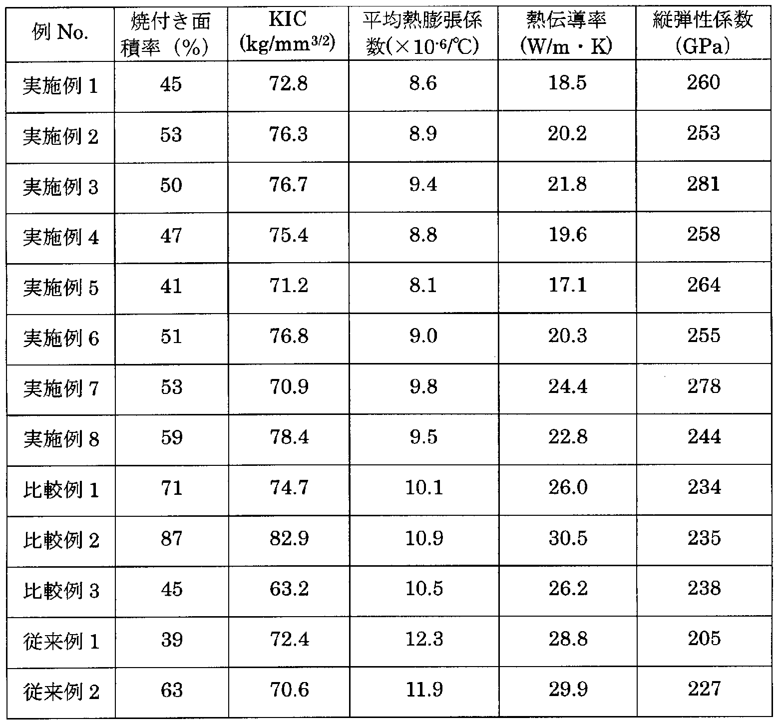
- Diameter m Average distance between MC carbides with an equivalent circle diameter of 15 m or more, the maximum value of the inscribed circle diameter of the area m) without MC carbide with an equivalent circle diameter of 15 m or more, Vickers hardness (Hv), wear depth (m), surface roughness Rz (m), seizure area ratio (%), fracture toughness value KIC (kg / mm 3/2 ), average thermal expansion coefficient (X 10- 6 / ° C), thermal conductivity (W / nrK), and a longitudinal elastic coefficient (GPa) was measured by the following method. Table 3 shows the measurement results.
- Each specimen is mirror-polished and electrolytically corroded with potassium dichromate aqueous solution. After corroding the compound in black, using an image analyzer (SPICCA-II, manufactured by NIPPON APIOTAS CO., LTD.) With 20 fields of view corresponding to the 0.23mm x 0.25mm part of the test piece. The area ratio (%) of MC carbide was measured and the measured values were averaged.
- SPICCA-II manufactured by NIPPON APIOTAS CO., LTD.
- M C, M C and M C carbides with a circle equivalent diameter of 1 ⁇ m or more were measured.
- Each specimen is mirror-polished, and the MC carbide is corroded to black by electrolytic corrosion with an aqueous potassium dichromate solution. Then, using the above image analyzer, 0.23mm x 0.25 for each specimen.
- the average carbide equivalent diameter m) of MC carbide was measured from 20 arbitrary fields of view corresponding to the mm portion, and the measured values were averaged.
- the average distance ( ⁇ m) between MC carbides with equivalent circle diameters of 15 m or more was measured, and the measured values were averaged.
- Each test piece is mirror-polished and lightly corroded with a picric acid ethanol solution. Then, using a Vickers hardness tester, the picker can be picked up at a load of 50 to 200 g at any five locations on the test piece. The hardness (Hv) was measured and the measured values were averaged.
- the depth of wear ( ⁇ m) and the 10-point average surface roughness Rz were measured on the rolled roll. was measured as follows.
- the surface roughness Rz was measured with a stylus type surface roughness meter.
- the rolling wear tester is a test roll 52 consisting of a small sleeve roll having an outer diameter of 60 mm, an inner diameter of 40 mm and a width of 40 mm manufactured according to Examples 1 to 8, Comparative Examples 1 to 3, and Conventional Examples 1 and 2, respectively. , 53, a heating furnace 54, a cooling water tank 55, a scraper 56, and a tension controller 57.
- the rolling wear test conditions were as follows.
- the seizure tester schematically shown in FIG. 12 includes a table 63 on which a test piece 61 is placed, a rack 68 whose lower end is in contact with the upper surface of the test piece 61, and a pion 60 that engages with the rack 68.
- the weight 69 falls on the rack 68, and the pinion 60 is swung into the test piece 61! /, And the rubbing member 62 (made of mild steel) is provided.
- the pion 60 is rotated, and the pinching member 62 is strongly pressed against the test piece 61, and an indentation is made on the test piece 61.
- the burn-in area ratio of the test piece 61 is calculated from the burn-in area Z indentation area (%). This seizure test was performed twice on each specimen, and the average value of the seizure area ratio was determined.
- the average thermal expansion coefficient from room temperature to 300 ° C. of each test piece processed to 8 mm ⁇ 8 mm ⁇ 17 mm was measured with a thermal stress strain measuring device (SSC / 5200 manufactured by Seiko Denshi Kogyo Co., Ltd.).
- the thermal conductivity at 300 ° C of each specimen processed to a diameter of 10 mm and a thickness of 1 mm was measured by the laser single flash method.
- the longitudinal elastic modulus of each test piece processed to a width of 10 mm, a length of 60 mm, and a thickness of 1.5 mm was measured by the free resonance natural vibration method.
- Example 1 40.9 0.6 18 20.0
- Example 2 32.5 0.1 28 48.3
- Example 3 33.5 0.3 42 59.4
- Example 4 38.3 0.8 20 26.0
- Example 5 54.6 1.7 13 14.3
- Example 6 32.9 0.0 31 49.6
- Example 7 22.3 2.9 47 65.8
- Example 8 23.2 0.4 17 32.3 Comparative Example 1 26.8 0.2 22 61.6
- Comparative Example 2 8.9 0.0 4 17.2
- Comparative Example 3 15.4 24.9 11 84.7 Conventional Example 1 5.7 0.0 6 32.4
- Conventional example 2 7.4 8.5 8 52.0
- Table 3 (continued)
- FIGS. 13 and 14 show the metal structures of the test pieces of Example 4 and Comparative Example 1, respectively.
- the white part is MC carbide and the black part is the base.
- MC carbide is distributed at a high concentration, but in the test piece of Comparative Example 1, the MC carbide is partially unevenly distributed.
- FIG. 15 shows the metal structure of the high-speed roll material of Conventional Example 2.
- White fine granular parts are MC carbide
- white mesh parts are MC, MC and MC carbide
- Examples 1 to 8 are approximately half or less than that of Conventional Example 1, indicating that the wear resistance is extremely good. It can also be seen that Examples 1 to 8 are superior to conventional examples in terms of deviations in rough skin resistance, seizure resistance and toughness.
- Fig. 16 shows the relationship between the area ratio of MC carbide and the value of (V% + 0.55 X Nb%) in equation (1). The relationship between the two is almost linear. When (V% + 0.55 X Nb%) is about 15% by mass or more, the area ratio of MC carbide is about 20% or more.
- FIG. 17 shows the thermal expansion coefficients of Example 4, Comparative Example 1 and Conventional Example 2 at 100 ° C. to 600 ° C.
- the horizontal axis indicates the temperature (° C)
- the vertical axis indicates the average thermal expansion coefficient (X 10 1 6 /. C) from room temperature to each temperature.
- Examples 4 to 8 are all 10 X 10- 6 Z ° C hereinafter, it is possible to greatly suppress the thermal crown I understand that.
- FIG. 18 shows the thermal conductivity of Example 4, Comparative Example 1 and Conventional Example 2 from room temperature to 600 ° C.
- the horizontal axis represents temperature (° C)
- the vertical axis represents thermal conductivity (W / m'K).
- the thermal conductivity at 300 ° C was less than 20 W / m'K in Example 4 and was over 25 W / m'K in Comparative Example 1 and 30 W / m'K in Conventional Example 2 Met.
- the thermal conductivity of Examples 4 to 8 at 300 ° C is all 25 W / m'K or less, indicating that the thermal crown can be significantly suppressed. This is considered to be because MC carbide is dispersed by 20% or more in area ratio. In particular, if the area ratio of MC carbide exceeds 30%, the thermal conductivity at 300 ° C will be 21 W / m'K or less, and the thermal crown suppression effect will increase.
- the longitudinal elastic moduli of Examples 4 to 8 were all 240 GPa or more, and especially those having a large area percentage of MC carbide showed a significantly higher longitudinal elastic modulus than the conventional material.
- Comparative Example 2 includes C content, formula (2), MC carbide area ratio, base hardness, and MC carbide
- the average equivalent circle diameter was outside the scope of the present invention and exceeded the B / A force. Therefore, it was inferior in wear resistance and seizure resistance.
- the room average thermal expansion coefficient at ⁇ 300 ° C is greater than 10 X 10- 6 Z ° C, and because the thermal conductivity at 300 ° C is 25 W / m'K than the growth of mono- circle crown Can not be suppressed enough.
- Comparative Example 3 includes V content, formulas (1) and (2), MC carbide area ratio, and M C
- the total area ratio of MC and MC carbide was outside the scope of the present invention, and B / A was more than 2.
- the average thermal bulging expansion coefficient at room temperature ⁇ 300 ° C is the 10 X 10- 6 Z ° C greater, and because the thermal conductivity at 300 ° C is 25 W / m'K greater, the growth of thermal crown I can't suppress it enough!
Landscapes
- Chemical & Material Sciences (AREA)
- Engineering & Computer Science (AREA)
- Mechanical Engineering (AREA)
- Materials Engineering (AREA)
- Metallurgy (AREA)
- Organic Chemistry (AREA)
- Physics & Mathematics (AREA)
- General Engineering & Computer Science (AREA)
- Thermal Sciences (AREA)
- Crystallography & Structural Chemistry (AREA)
- Geometry (AREA)
- Reduction Rolling/Reduction Stand/Operation Of Reduction Machine (AREA)
- Rolls And Other Rotary Bodies (AREA)
Abstract
Description


Claims
Priority Applications (5)
| Application Number | Priority Date | Filing Date | Title |
|---|---|---|---|
| JP2006535156A JP4831346B2 (ja) | 2004-09-13 | 2005-09-13 | 圧延ロール用遠心鋳造外層及びその製造方法 |
| US11/575,127 US8156651B2 (en) | 2004-09-13 | 2005-09-13 | Centrifugally cast external layer for rolling roll and method for manufacture thereof |
| CN2005800305916A CN101018880B (zh) | 2004-09-13 | 2005-09-13 | 轧辊用离心铸造外层及其制造方法 |
| EP05783460.8A EP1832665B1 (en) | 2004-09-13 | 2005-09-13 | Centrifugally cast external layer for rolling roll and method for manufacture thereof |
| KR1020077007421A KR101312597B1 (ko) | 2004-09-13 | 2005-09-13 | 압연 롤용 원심 주조 외층 및 그 제조 방법 |
Applications Claiming Priority (4)
| Application Number | Priority Date | Filing Date | Title |
|---|---|---|---|
| JP2004265628 | 2004-09-13 | ||
| JP2004-265628 | 2004-09-13 | ||
| JP2005117008 | 2005-04-14 | ||
| JP2005-117008 | 2005-04-14 |
Publications (1)
| Publication Number | Publication Date |
|---|---|
| WO2006030795A1 true WO2006030795A1 (ja) | 2006-03-23 |
Family
ID=36060046
Family Applications (1)
| Application Number | Title | Priority Date | Filing Date |
|---|---|---|---|
| PCT/JP2005/016859 Ceased WO2006030795A1 (ja) | 2004-09-13 | 2005-09-13 | 圧延ロール用遠心鋳造外層及びその製造方法 |
Country Status (6)
| Country | Link |
|---|---|
| US (1) | US8156651B2 (ja) |
| EP (1) | EP1832665B1 (ja) |
| JP (1) | JP4831346B2 (ja) |
| KR (1) | KR101312597B1 (ja) |
| CN (1) | CN101018880B (ja) |
| WO (1) | WO2006030795A1 (ja) |
Cited By (2)
| Publication number | Priority date | Publication date | Assignee | Title |
|---|---|---|---|---|
| JP2007144442A (ja) * | 2005-11-25 | 2007-06-14 | Hitachi Metals Ltd | 圧延用複合ロール |
| WO2018043534A1 (ja) | 2016-09-02 | 2018-03-08 | Jfeスチール株式会社 | 圧延用ロール外層材および圧延用複合ロール |
Families Citing this family (24)
| Publication number | Priority date | Publication date | Assignee | Title |
|---|---|---|---|---|
| EP1832665B1 (en) * | 2004-09-13 | 2013-04-10 | Hitachi Metals, Ltd. | Centrifugally cast external layer for rolling roll and method for manufacture thereof |
| CN101351569B (zh) | 2005-12-28 | 2011-05-11 | 日立金属株式会社 | 离心铸造复合轧辊 |
| SE0600841L (sv) * | 2006-04-13 | 2007-10-14 | Uddeholm Tooling Ab | Kallarbetsstål |
| WO2008101550A1 (de) * | 2007-02-20 | 2008-08-28 | Siemens Aktiengesellschaft | Walze und/oder rolle sowie ein verfahren zur herstellung einer walze und/oder rolle |
| PH12012501570A1 (en) * | 2010-02-05 | 2012-10-22 | Weir Minerals Australia Ltd | Hard metal materials |
| CN102189113B (zh) * | 2011-03-10 | 2013-02-13 | 江阴润源机械有限公司 | 一种轧机的合金钢支撑辊及其制造工艺 |
| CN102146547B (zh) * | 2011-03-10 | 2012-10-03 | 江阴润源机械有限公司 | 一种合金钢轧辊及其制造工艺 |
| BR112014006751B1 (pt) * | 2011-09-21 | 2021-12-28 | Hitachi Metals, Ltd | Rolo compósito fundido centrifugamente para laminação a quente e método de produção do mesmo |
| WO2013150950A1 (ja) * | 2012-04-02 | 2013-10-10 | 日立金属株式会社 | 遠心鋳造製複合ロール及びその製造方法 |
| EP2660344A1 (en) * | 2012-05-04 | 2013-11-06 | Akers AB | Centrifugally cast roll for last finishing stands in hot strip mills |
| CN102851597B (zh) * | 2012-09-14 | 2014-04-16 | 江苏久联冶金机械制造有限公司 | 一种抗磨蚀沉没辊轴套及其制造方法 |
| JP5949596B2 (ja) * | 2013-03-01 | 2016-07-06 | Jfeスチール株式会社 | 熱間圧延用ロール外層材、および熱間圧延用複合ロール |
| AT514133B1 (de) * | 2013-04-12 | 2017-06-15 | Feistritzer Bernhard | Ringförmiges Werkzeug |
| TWI469835B (zh) * | 2013-07-18 | 2015-01-21 | Hitachi Metals Ltd | Centrifugal casting legal compound roll and its manufacturing method |
| CN105579156B (zh) | 2013-09-25 | 2018-02-27 | 日立金属株式会社 | 离心铸造制热轧用复合辊 |
| KR102219332B1 (ko) * | 2013-09-25 | 2021-02-22 | 히타치 긴조쿠 가부시키가이샤 | 원심 주조제 복합 롤 및 그 제조 방법 |
| CN105131788B (zh) * | 2015-09-21 | 2017-05-31 | 盐城市昶桦户外用品股份有限公司 | 一种户外帐篷用支撑杆及生产工艺 |
| CN105671421A (zh) * | 2016-04-22 | 2016-06-15 | 柳州凯通新材料科技有限公司 | 铬锰钨系白口铸铁及其加工工艺 |
| WO2018042929A1 (ja) * | 2016-09-02 | 2018-03-08 | Jfeスチール株式会社 | 圧延用ロール外層材および圧延用複合ロール |
| BR112019014439B1 (pt) * | 2017-02-08 | 2023-10-03 | Proterial, Ltd | Rolo compósito para laminação e seu método de produção |
| CN107511398B (zh) * | 2017-08-09 | 2019-07-02 | 三鑫重工机械有限公司 | 一种抗磨型带钢用强展轧辊 |
| WO2019191400A1 (en) | 2018-03-29 | 2019-10-03 | Oerlikon Metco (Us) Inc. | Reduced carbides ferrous alloys |
| CN109317520B (zh) * | 2018-11-23 | 2019-12-20 | 枣庄瑞兴机械制造有限公司 | 用于钢管轧机的复合辊套及其制造方法 |
| CN115070004B (zh) * | 2022-05-20 | 2023-05-05 | 中钢集团邢台机械轧辊有限公司 | 一种金属型离心辊环的铸造方法 |
Citations (2)
| Publication number | Priority date | Publication date | Assignee | Title |
|---|---|---|---|---|
| JPH08302444A (ja) * | 1995-03-07 | 1996-11-19 | Kawasaki Steel Corp | 遠心鋳造ロール用外層材 |
| JP2000288708A (ja) * | 1999-04-01 | 2000-10-17 | Nippon Steel Corp | 圧延用スリーブロール |
Family Cites Families (27)
| Publication number | Priority date | Publication date | Assignee | Title |
|---|---|---|---|---|
| US3670800A (en) * | 1968-06-12 | 1972-06-20 | United States Pipe Foundry | Casting process for rolls |
| JPS56151149A (en) * | 1980-04-23 | 1981-11-24 | Kubota Ltd | Assembling type roll for continuous casting of slab |
| US4721153A (en) * | 1986-09-12 | 1988-01-26 | Hitachi Metals, Inc. | High-chromium compound roll |
| US4726417A (en) * | 1986-09-12 | 1988-02-23 | Hitachi Metals, Ltd. | Adamite compound roll |
| WO1988007594A1 (fr) * | 1987-03-24 | 1988-10-06 | Hitachi Metals, Ltd. | Rouleau composite resistant a l'abrasion et procede de production |
| US5167068A (en) * | 1988-04-28 | 1992-12-01 | Valmet Paper Machinery Inc. | Method for manufacturing a roll directly contacting a web |
| US5265911A (en) * | 1989-01-12 | 1993-11-30 | Goode David P | Composite ski pole and method of making same |
| JP2960458B2 (ja) | 1990-02-28 | 1999-10-06 | 日立金属株式会社 | 耐摩耗複合ロール |
| US5225007A (en) * | 1990-02-28 | 1993-07-06 | Hitachi Metals Ltd. | Method for wear-resistant compound roll manufacture |
| KR950006649B1 (ko) * | 1990-06-13 | 1995-06-21 | 신닛뽄 세이데쓰 가부시끼가이샤 | 압연용 복합로울 및 그것의 제조방법 |
| JPH04158910A (ja) * | 1990-10-19 | 1992-06-02 | Hitachi Ltd | 圧延用複合ロール及びその製造法 |
| DE69213608T2 (de) * | 1991-07-09 | 1997-02-06 | Hitachi Metals Ltd | Verbundwalze und Verfahren zur Herstellung derselben |
| EP0562114B1 (en) * | 1991-09-12 | 1998-11-04 | Kawasaki Steel Corporation | Material of outer layer of roll for rolling and compound roll manufactured by centrifugal casting |
| JP3205745B2 (ja) | 1993-03-31 | 2001-09-04 | 日立金属株式会社 | 耐摩耗耐焼付性熱間圧延用ロール |
| JPH07188841A (ja) * | 1993-12-27 | 1995-07-25 | Kanto Special Steel Works Ltd | 冷間圧延用ワークロール |
| JPH07268569A (ja) | 1994-03-31 | 1995-10-17 | Hitachi Metals Ltd | 耐摩耗焼結合金及びそれを用いた圧延ロール |
| JP2841276B2 (ja) * | 1994-06-29 | 1998-12-24 | 川崎製鉄株式会社 | 熱間圧延用ロール外層材及び熱間圧延用ロールの製造方法 |
| JPH0860289A (ja) | 1994-08-24 | 1996-03-05 | Nippon Steel Corp | 遠心鋳造複合ロール |
| TW341602B (en) * | 1996-03-15 | 1998-10-01 | Kawasaki Steel Co | Outer layer material for centrifugally cast roll |
| DE69718760T2 (de) * | 1996-06-18 | 2003-06-12 | Kawasaki Steel Corp., Kobe | Walze zum warmwalzen mit sehr hoher verschleissfestigkeit und reduzierter karbidentmischung |
| EP0911421B1 (en) * | 1997-04-08 | 2003-03-19 | Nippon Steel Corporation | Composite work roll for cold rolling |
| JP3582400B2 (ja) | 1999-04-20 | 2004-10-27 | Jfeスチール株式会社 | 耐事故性に優れた遠心鋳造製熱間圧延仕上後段スタンド用複合ロール |
| AT408666B (de) * | 1999-04-22 | 2002-02-25 | Weinberger Eisenwerk | Gusswerkstoff und verfahren zu dessen herstellung |
| JP3755396B2 (ja) | 2000-10-30 | 2006-03-15 | Jfeスチール株式会社 | 熱間圧延用ロール外層材および耐クラック性に優れた遠心鋳造製熱間圧延用複合ロール |
| JP2004114048A (ja) | 2002-09-24 | 2004-04-15 | Hitachi Metals Ltd | 耐摩耗性冷間圧延用ロール |
| EP1832665B1 (en) * | 2004-09-13 | 2013-04-10 | Hitachi Metals, Ltd. | Centrifugally cast external layer for rolling roll and method for manufacture thereof |
| CN101351569B (zh) * | 2005-12-28 | 2011-05-11 | 日立金属株式会社 | 离心铸造复合轧辊 |
-
2005
- 2005-09-13 EP EP05783460.8A patent/EP1832665B1/en not_active Revoked
- 2005-09-13 CN CN2005800305916A patent/CN101018880B/zh not_active Expired - Fee Related
- 2005-09-13 JP JP2006535156A patent/JP4831346B2/ja not_active Expired - Fee Related
- 2005-09-13 US US11/575,127 patent/US8156651B2/en not_active Expired - Fee Related
- 2005-09-13 WO PCT/JP2005/016859 patent/WO2006030795A1/ja not_active Ceased
- 2005-09-13 KR KR1020077007421A patent/KR101312597B1/ko not_active Expired - Fee Related
Patent Citations (2)
| Publication number | Priority date | Publication date | Assignee | Title |
|---|---|---|---|---|
| JPH08302444A (ja) * | 1995-03-07 | 1996-11-19 | Kawasaki Steel Corp | 遠心鋳造ロール用外層材 |
| JP2000288708A (ja) * | 1999-04-01 | 2000-10-17 | Nippon Steel Corp | 圧延用スリーブロール |
Cited By (3)
| Publication number | Priority date | Publication date | Assignee | Title |
|---|---|---|---|---|
| JP2007144442A (ja) * | 2005-11-25 | 2007-06-14 | Hitachi Metals Ltd | 圧延用複合ロール |
| WO2018043534A1 (ja) | 2016-09-02 | 2018-03-08 | Jfeスチール株式会社 | 圧延用ロール外層材および圧延用複合ロール |
| KR20190035834A (ko) | 2016-09-02 | 2019-04-03 | 제이에프이 스틸 가부시키가이샤 | 압연용 롤 외층재 및 압연용 복합 롤 |
Also Published As
| Publication number | Publication date |
|---|---|
| CN101018880A (zh) | 2007-08-15 |
| JP4831346B2 (ja) | 2011-12-07 |
| CN101018880B (zh) | 2011-06-01 |
| EP1832665A1 (en) | 2007-09-12 |
| KR101312597B1 (ko) | 2013-09-30 |
| US8156651B2 (en) | 2012-04-17 |
| EP1832665B1 (en) | 2013-04-10 |
| EP1832665A4 (en) | 2009-08-26 |
| KR20070051356A (ko) | 2007-05-17 |
| JPWO2006030795A1 (ja) | 2008-05-15 |
| US20080226936A1 (en) | 2008-09-18 |
Similar Documents
| Publication | Publication Date | Title |
|---|---|---|
| JP4831346B2 (ja) | 圧延ロール用遠心鋳造外層及びその製造方法 | |
| JP5950048B2 (ja) | 遠心鋳造製熱間圧延用複合ロール | |
| JP5024051B2 (ja) | 遠心鋳造複合ロール | |
| JP6908021B2 (ja) | 圧延ロール用外層及び圧延用複合ロール | |
| WO2015045985A1 (ja) | 遠心鋳造製熱間圧延用複合ロール | |
| CN112760561B (zh) | 一种手工工具用盘条及其制备方法 | |
| JP4922971B2 (ja) | 熱間圧延用複合ロール及びその製造方法 | |
| JP3925308B2 (ja) | 熱間圧延用ロール外層材および熱間圧延用複合ロール | |
| WO2019045068A1 (ja) | 圧延用複合ロール及びその製造方法 | |
| JP2007175736A (ja) | 圧延用複合ロールおよびその製造方法 | |
| JP2004162104A (ja) | 熱間圧延用ロール外層材および熱間圧延用複合ロール | |
| JP2007196257A (ja) | 圧延用ロール | |
| JP4650733B2 (ja) | 圧延ロール用外層材および圧延ロール | |
| JP4596312B2 (ja) | 耐摩耗性および耐熱亀裂性に優れる圧延ロール用外層材およびそれを用いた圧延ロール | |
| JP3030077B2 (ja) | 耐クラック性に優れた耐摩耗複合ロール及びその製造方法 | |
| JP4650731B2 (ja) | 圧延用複合ロール | |
| JP4650738B2 (ja) | 圧延用複合ロール | |
| JP4650728B2 (ja) | 圧延用複合ロール | |
| JP4650736B2 (ja) | 圧延用複合ロール | |
| JP2007185681A (ja) | 圧延用ロール | |
| JP2007160391A (ja) | 圧延ロール | |
| JP2007146276A (ja) | 圧延用複合ロール | |
| JPH09170042A (ja) | 遠心鋳造製ロールとその製造方法 |
Legal Events
| Date | Code | Title | Description |
|---|---|---|---|
| AK | Designated states |
Kind code of ref document: A1 Designated state(s): AE AG AL AM AT AU AZ BA BB BG BR BW BY BZ CA CH CN CO CR CU CZ DE DK DM DZ EC EE EG ES FI GB GD GE GH GM HR HU ID IL IN IS JP KE KG KM KP KR KZ LC LK LR LS LT LU LV MA MD MG MK MN MW MX MZ NA NG NI NO NZ OM PG PH PL PT RO RU SC SD SE SG SK SL SM SY TJ TM TN TR TT TZ UA UG US UZ VC VN YU ZA ZM ZW |
|
| AL | Designated countries for regional patents |
Kind code of ref document: A1 Designated state(s): BW GH GM KE LS MW MZ NA SD SL SZ TZ UG ZM ZW AM AZ BY KG KZ MD RU TJ TM AT BE BG CH CY CZ DE DK EE ES FI FR GB GR HU IE IS IT LT LU LV MC NL PL PT RO SE SI SK TR BF BJ CF CG CI CM GA GN GQ GW ML MR NE SN TD TG |
|
| 121 | Ep: the epo has been informed by wipo that ep was designated in this application | ||
| WWE | Wipo information: entry into national phase |
Ref document number: 2006535156 Country of ref document: JP |
|
| WWE | Wipo information: entry into national phase |
Ref document number: 200580030591.6 Country of ref document: CN |
|
| NENP | Non-entry into the national phase |
Ref country code: DE |
|
| WWE | Wipo information: entry into national phase |
Ref document number: 1020077007421 Country of ref document: KR |
|
| WWE | Wipo information: entry into national phase |
Ref document number: 2005783460 Country of ref document: EP |
|
| WWP | Wipo information: published in national office |
Ref document number: 2005783460 Country of ref document: EP |
|
| WWE | Wipo information: entry into national phase |
Ref document number: 11575127 Country of ref document: US |