SYSTEM AND METHOD OF ELIMINATING OR MINIMIZING LO-RELATED
INTERFERENCE FROM TUNERS
CROSS-REFERENCE TO RELATED APPLICATIONS
[0001] The present invention is related to co-pending and commonly assigned United States Patent Applications serial number 10/319,118 entitled "System and Method for Discovering Frequency Related Spurs in a Multi-Conversion Tuner," filed March 13, 2002, serial number 08/904,693 entitled "Dual Mode Tuner for Co- Existing Digital and Analog Television Signals," filed August 1, 1997, and serial number 09/572,393 entitled "Broadband Integrated Tuner," filed May 16, 2000, the disclosures of which are hereby incorporated herein by reference in their entirety.
25571991.1
SYSTEM AND METHOD OF ELIMINATING OR MINIMIZING LO-RELATED
INTERFERENCE FROM TUNERS
TECHNICAL FIELD
[0002] The invention generally relates to tuner circuits and more particularly to the elimination or reduction of spurious signals in two or more single or multiple conversion tuners by dynamic selection of the frequency of a first IF signal.
25571991.1
BACKGROUND OF THE INVENTION
[0003] Devices requiring two or more tuners or frequency converters are well known. Plug-and-Play™, TiVo™, set-top boxes and televisions with picture-in- picture are examples of such devices. In the current state of the art, tuners are often separately packaged and engage separate portions of the device in order to minimize tuner interference. By maintaining some physical separation between tuners of such devices cross-talk and interference generated by the tuners can be minimized. However, the ability to maintain useful separation between tuners has been limited as the size of such devices continues to diminish. Development is also being made to integrate two or more tuners on a single circuit board. One challenge of miniaturization of such devices is the elimination or minimization of multi-tuner interference. RF shielding and/or extensive RF filtering and circuitry is often needed to suppress tuner generated interference.
[0004] To improve sensitivity and selectivity in modern tuners, there is a need to minimize noise and spurious frequency elements (spurs) that can occur in the tuner output. Spurs can be generated from multiple sources, such as internal switching, quantization noise, or other device components. As described in more detail below, tuners can also be sources of spurs. The identification of intra-tuner spurs in multi- conversion tuners is the subject of U.S. Serial No. 10/319,118, entitled "System and Method for Discovering Frequency Related Spurs in a Multi-Conversion Tuner," hereby incorporated by reference herein. In a multiple tuner device, spurs may include intra- tuner spurs and inter-tuner spurs generated by local oscillators of the tuners. Other spur types and sources also exist.
[0005] Single conversion and multiple conversion tuners are well known. Such tuners often utilize one or more local oscillators in the mixing process. Examples of double conversion tuners are shown as tuners 106 and 108 in FIGURE 1. In a double conversion tuner, an incoming signal at frequency /J
N is mixed with a signal at frequency /
LOI from a local oscillator (LO) to produce a signal at an intermediate frequency /J
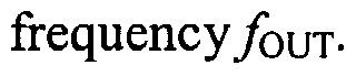
F. This signal is then mixed with a signal at frequency /
LO2 from a second local oscillator to produce the desired output
The frequencies of the first and second LO
25571991.1
signals are usually selected so that the first IF signal and output signal occur either at a specific frequency or within a specified frequency range.
[0006] Devices having multiple tuners are also well known. A dual tuner system is shown as tuner system 100 in FIGURE 1. Specifically, tuner system 100 includes a pair of double conversion tuners 106 and 108, although a multiple tuner system may comprise other tuner configurations (e.g., single conversion tuners or a combination of single and multiple conversion tuners), hi a dual tuner system, multiple LO' s may be utilized to produce two desired output frequencies, foυτ,ι and/ouτ,2- hi the example of FIGURE 1, each tuner 106 and 108 includes a pair of mixers, shown here as mixers 110 and 112 and mixers 114 and 116, respectively, wherein the/LOij signals are mixed to produceybuτ,i andyόuτ,2-
[0007] To improve sensitivity and selectivity in modern tuners, there is a need to minimize noise and spurious frequency elements (spurs) that can occur in the tuner output(s). Spurs can be generated from multiple sources, such as internal switching, quantization noise, or other device components. As described in more detail below, tuners can also be sources of spurs. Generally any or all spurious signals are undesirable and, if possible, should be reduced or eliminated to enhance tuner operation.
[0008] Single tuner systems can have intra-tuner spurs related to the frequency harmonics of one or more associated local oscillators. In single-conversion tuners, spurs may be related to the harmonics of its associated local oscillator, hi double conversion tuners, spurs may be related to combinations of the harmonics of the first and second local oscillators frequencies (/Lo i and /Lθ2)- The identification of intra-tuner spurs in multi-conversion tuners is the subject of the above referenced patent application entitled "System and Method for Discovering Frequency Related Spurs in a Multi- Conversion Tuner."
[0009] Multiple tuner systems can be affected by both intra-tuner spurs and inter-tuner spurs. As in a single tuner system, each tuner of a multiple tuner system may be affected by intra-tuner spurs related to the harmonics of its own local oscillator(s). Additionally, each tuner in a multiple tuner system may be affected by inter-tuner spurs
25571991.1
which are spurs related to frequency harmonics of local oscillators of both the subject tuner and any neighboring tuner(s).
[0010] An efficient method of eliminating or minimizing the effects of spurs in multiple tuner systems would be desirable.
25571991.1
BRIEF SUMMARY OF THE INVENTION
[0011] The present invention is directed to systems and methods of eliminating or reducing interference resulting from harmonics of local oscillator frequencies of the mixers. In one embodiment, a determination is made as to a zone or zones in which harmonics result in undesired spur generation. In preferred embodiments of the invention, one or more exclusion zones of local oscillator frequency combinations are identified within which spurs are generated. In some situations spurs in the tuner output are unavoidable. For example, the opportunity to adjust local oscillators may be limited to a range of frequencies within which one or more spurs always exist. As some spurs are more significant (e.g., cause greater interference) than other spurs, preferred embodiments of the invention may also determine a score for identified spurs which may be used to optimally select from within a set of spur-generating local oscillator frequencies.
[0012] In one embodiment, a method of the present invention identifies inter-tuner spurs and intra-tuner spurs and utilizes frequency information of the identified spurs to define a plurality of exclusion zones. LO frequencies may subsequently be efficiently selected in view of the exclusion zone information. In a preferred embodiment, the selection of local oscillator frequencies hinges on the selection of a preferred intermediate frequency, IF, of the tuner. As described herein, a preferred IF may be identified with knowledge of the boundaries of the exclusion zone.
[0013] The foregoing has outlined rather broadly the features and technical advantages of the present invention in order that the detailed description of the invention that follows may be better understood. Additional features and advantages of the invention will be described hereinafter which form the subject of the claims of the invention. It should be appreciated by those skilled in the art that the conception and specific embodiment disclosed may be readily utilized as a basis for modifying or designing other structures for carrying out the same purposes of the present invention. It should also be realized by those skilled in the art that such equivalent constructions do not depart from the spirit and scope of the invention as set forth in the appended claims. The novel features which are believed to be characteristic of the invention, both as to its organization and method of operation, together with further objects and advantages will
25571991.1
be better understood from the following description when considered in connection with the accompanying figures. It is to be expressly understood, however, that each of the figures is provided for the purpose of illustration and description only and is not intended as a definition of the limits of the present invention.
25571991.1
BRIEF DESCRIPTION OF THE DRAWINGS
[0014] For a more complete understanding of the present invention, reference is now made to the following descriptions taken in conjunction with the accompanying drawing, in which:
[0015] FIGURE 1 is a simplified diagram of a multiple tuner system of the prior art, wherein each tuner has a pair of mixing stages;
[0016] FIGURE 2 shows one embodiment of a system using the concepts of the present invention;
[0017] FIGURE 3 illustrates a double conversion tuner having a spurious signal in an output band of a tuner;
[0018] FIGURE 4 illustrates the double conversion tuner of FIGURE 3 wherein the spurious signal has been shifted out of the output band of the tuner and into an adjacent channel;
[0019] FIGURE 5 shows the shift in intermediate frequency IF which resulted in the spurious signal shift of FIGURE 4;
[0020] FIGURE 6 shows the shift in intermediate frequency IF which results in a spurious signal shift to another adjacent channel;
[0021] FIGURE 7 shows a range or intermediate frequencies within which the spurious signal will remain in the output band of the tuner;
[0022] FIGURE 8 shows an example of a method of practicing concepts of the present invention; and
[0023] FIGURE 9 shows one embodiment of a method of practicing concepts of the present invention.
2557199K1
DETAILED DESCRIPTION OF THE INVENTION
[0024] One of the known approaches to spur elimination is to change the LO frequencies of the tuner in order to shift the spur outside of an output bandwidth or an output band of interest. For a given spur (such as a spur associated with two times the first LO and three times the second LO) that falls within the output pass band, the LO frequencies can be changed (up or down) a certain amount, which will, in effect, still allow the circuit to tune to the desired output frequency, but the spur will be shifted up or down and outside of the output bandwidth of the tuner. The invention disclosed herein is directed, in one aspect, toward efficient selection of LO frequencies in order to eliminate a spur. The concepts of the present invention may be applied to eliminate or minimize LO-related interference in single tuner systems (e.g., intra-tuner spurs in multi- conversion tuners) as well as to eliminate or minimize LO-related interference in multiple tuner systems (e.g., intra-tuner spurs in multi-conversion tuners and inter-tuner spurs between multiple tuners).
[0025] Efficient identification of spurs is desirable. One method for identifying spurs falling within a particular band, such as the tuner output band or other band of interest, is to look at all the harmonics of the first LO, mixed with all the harmonics of the second LO and, one by one, check off each one. Thus, if a circuit designer is looking up to the 15th harmonic of the first LO and the 15th harmonic of the second LO, the designer checks one times/Leu (first harmonic) and one times/Lo2 (first harmonic) to see if there is a spur of concern. If there is no spur of concern, then the designer continues with one times/Loi (first harmonic) and two times /Lo2 (second harmonic) to see if there is a spur of concern. If not, then the process continues with one times /LOI (first harmonic) and three times/Lew (third harmonic) to see if there is a spur of concern. Once all harmonics of fun have been considered, the harmonic of the first LO frequency may be incremented and each harmonic of the second LO frequency again considered. That is, the designer continues with two times /LOI (second harmonic) and one times /LO2 (first harmonic) to see if there is a spur of concern, and so on. This results in n2 combinations being looked at. This is a time consuming method. Even assuming that the mathematics of how spurs are generated allows for the elimination of quite a few of the coefficients for the first and second LO, the operation remains essentially an n2 operation.
25571991.1
[0026] Another method for identifying spurs is disclosed in the above referenced patent application entitled "System and Method for Discovering Frequency Related Spurs in a Multi-Conversion Tuner." In a disclosed embodiment, a determination is made as to a band or bands in which harmonics could possibly result in interference and determining which combination of LO frequencies result in harmonics not falling within the determined band or bands. Preferred embodiments leverage the fact that harmonics of a particular frequency are evenly spaced to avoid examining all of the possible harmonics. For example, rather than calculate every harmonic and check that each calculated harmonic does not fall within the determined band or bands, embodiments of that invention determine the smallest harmonics that are greater than each edge of the determined band or bands. An interfering spur, a difference of the LO harmonics falling within the band or bands, may be determined to exist where the smallest harmonic difference for a particular LO harmonic that is greater than a first edge of a determined band is not equal to the smallest harmonic difference for the particular LO harmonic that is greater than a second edge of the determined band.
[0027] Once spurs have been identified, they can be eliminated by selecting different LO frequencies. Such LO frequency selection can be via a random process, e.g., a new set of LO frequencies can be randomly selected and the spur calculations again performed to determine whether a spur exists within the band of interest. However, a more efficient method for selecting alternative LO frequencies would be desirable.
[0028] FIGURE 2 shows a simplified block diagram of multiple tuner system 200 having a pair of double conversion tuners, shown here as tuners 210 and 220. Examples of devices comprising such a system include a set-top cable box, cable modem, Plug-and-Play™ device, TiVo™ device, and a television with picture-in-picture capability. RF signals are input to multiple tuner system 200. Although the illustrated embodiment shows RF signals being provided by cable system 230 and antenna 231, RF signals may be received from any number of sources, such as a satellite system, or other signal source.
[0029] In the illustrated embodiment of multiple tuner system 200, tuners 210 and 220 are double conversion tuners. However, embodiments of the present
25571991.1
invention may be utilized with respect to multiple tuner systems in which one or more tuners provide frequency conversion in a number of stages different than that illustrated, e.g., single conversion tuners, triple conversion tuners, quadruple conversion tuners, etcetera. Moreover, embodiments of the present invention may be utilized with respect to tuner systems having a number of tuners different than that illustrated, e.g., single tuner systems, triple tuner systems, quadruple tuner systems, etcetera. The exemplary embodiment, however, is shown and described with respect to multiple tuners, each having multiple frequency conversion stages, in order to concisely present concepts of the present invention.
[0030] A first mixer of tuner 210, mixer 211, is connected to the RF input signal, fiN, and the output, fu)i,i, of LO 212. Mixer 211 receives both the RF input signal, f^, and the first LO signal produced by LO 212, fLoi.i, and generates an output signal, which may be called the first IF, shown as fIFι. The frequency of the signal produced by LO 212 is controlled by a tuning a phase locked loop circuit, shown as circuit 213, which is, in turn, controlled by system controller 250 through a control interface.
[0031] The first IF signal, generated by mixer 211 , is connected through IF filter 214, which attenuates undesired signals. The output of IF filter 214 is connected to a second mixer of tuner 210, mixer 215. Once the first IF signal generated by mixer 211 has been filtered, it is mixed with a second local oscillator signal, fLoi,2, generated by local oscillator 216, whose output is connected to mixer 215. Mixer 215 operates to generate an output signal, fouτi- The frequency of the signal produced by LO 216 is controlled by tuning a phase locked loop circuit, shown as circuit 217, which is, in turn, controlled by system controller 250 through a control interface.
[0032] In a similar manner, tuner 220 has mixers 221 and 225, LOs 222 and 226, circuits 223 and 227, and EF filter 224. Tuner 220 of embodiments operates as described above with respect to tuner 210, although LOs 222 and 227 may be controlled independently of LOs 212 and 217 to provide a different signal (e.g., channel) as an output signal, foim, of tuner 220.
25571991.1
[0033] The output signals of tuners 210 and 220 of the illustrated embodiment are provided to using device 240, such as may comprise a set-top cable box, cable modem, Plug-and-Play™ device, TiVo™ device, a television with picture-in- picture capability, or the like. Using device 240 may comprise various circuits, such as demodulator 241, processor 242, and memory 243, utilized in further processing the signals output from tuners 210 and 222.
[0034] As a set of new (different) carrier frequencies are selected (e.g., one or more new channels are selected), one or more LO frequencies of tuners 210 and/or 220 are adjusted by operation of controller 250. LO frequencies should be carefully chosen to avoid spurious signals appearing in the output band of interest associated with tuners 210 and 220. Although a number of LO frequencies may provide conversion of a signal from a particular RF carrier frequency to a particular output frequency, many such LO frequency combinations will have spurs associated therewith which also fall within the IF frequency bandwidths and/or output frequency bandwidths of either or both of tuners 210 and 220. Accordingly, before implementation of a particular LO frequency combination for tuning to a desired signal by tuners 210 and 220, the LO-related spurs are analyzed according to embodiments of the invention for undesired spurs, hi device 200 of the illustrated embodiment, selection of LO frequencies and the associated spur analysis is done dynamically, such as at the time of channel selection. Accordingly, concepts of the present invention can be employed to minimize delay in tuning to selected channels.
[0035] One advantage of systems and methods of the present invention is time savings for alignment, when a tuner is used over a wide range of frequencies. In such a situation it is important to find the LO spurs quickly with as few calculations as possible as these calculations are made every time a channel is changed. Controller 250 of embodiments, which may be implemented in software, hardware or both, enables the first IF generated by the first mixer to be varied dynamically in order to solve the problem of spurious signal generation at certain channel values. Efficient selection of LO frequencies to avoid or minimize spurs is one object of an embodiment of the present invention.
25571991.1
[0036] A discussion of two types of spurs follows. Referring still to FIGURE 2, two double conversion tuners with a single RF input are provided. Each of the tuners has a separate output which may be a different (or the same) channel. Each tuner may have certain spurs, referred herein as "intra-tuner" spurs, which are related to the local oscillators of the associated tuner. The frequency of each of the intra-tuner LO- related spurs can be calculated as:
fSPUR = n X fl - m X f2 (!)
where n and m are integer numbers representing, respectively the harmonics of the high and low local oscillator frequencies, and/i and/^ are the local oscillator frequencies (e.g., /LOI and/Lo2, respectively where /Lo i >/LO2)- If any spur generated by a given combination of/Loi and/u)2 falls within the output bandwidth (fβψ) of the tuner, that spur can degrade the quality of the output signal.
[0037] Each tuner may also have "inter-tuner" spurs related to local oscillators of one or more neighboring tuners. Generation of these output spurs is dependent on the particular local oscillator frequencies of the neighbor tuner.
[0038] Inter-tuner spurs can be calculated as:
fsPURΛ = n X Λθl.1 + m X Λθl.2 - f IJOlA (2)
J SPUR,! = n X J £01,1 + m X J £01,2 ~~ J LOl, ,1 (^)
where n and m are integers and n\ < max harmonics and m < max_harmonics, and where max_harmonics = maximum number of harmonics of one tuner's LO which are present in another tuner's output, and where fLOX i = tuner i's first LO frequency and fwi i = tuner i's second LO frequency.
[0039] For the tuners 210 and 220 of FIGURE 2, equation (2) defines spurs falling within the output band of tuner 210, while equation (3) defines spurs falling within the output band of a tuner 220.
25571991.1
[0040] Therefore, intra-tuner and inter-tuner spur equations for multiple tuner systems are as follows:
f spuRa = n x fiou ~ m x fwu (4)
for z = 2 → «, fSPURΛ = n x fL0O + m x fwl l - fLO2 ] (5) and for i = 2 → n, fSPUR l = n x fwl l + m x fLOU - fLO2 l (6)
where equation (4) is an equation for intra-tuner spurs, equation (5) is an equation for inter-tuner spurs in a first tuner of a multiple tuner system, and equation (6) is an equation for inter-tuner spurs in tuners 2 through n in a multiple tuner system.
[0041] Equations (1) through (6) permit identification of two types of spurs in the tuner output band of interest. Other spurs may exist and could also be determined. As described herein, if a spur does exist within the desired output bandwidth, the LO frequencies may be adjusted to different values to avoid the spur falling within the output band.
[0042] The characteristic movement of spurs in response to different LO frequencies can be used to determine a particular range or continuum of first IF values yielding a spur in the output bandwidth. According to embodiments of the invention, this particular range of first IF values defines an exclusion zone of first IF values associated with a particular spur. First IF values within the exclusion zone yield a spur in the tuner output bandwidth. First BF values outside of the exclusion zone yield a tuner output which is free of the particular spur. In this manner, by selecting a particular EF value a known spur may be rejected at the output. At other times, a spur- free tuner output may not be possible and a choice between known spurs may be required in order to minimize the detrimental effect on tuner performance. As described herein in further detail, a scoring system can be utilized to rank particular spurs and to facilitate selection of local oscillator frequencies yielding a spur with minimal detrimental effect on tuner performance.
25571991 1
[0043] The frequency of a spur within the output bandwidth is a function of associated local oscillator frequencies. In multiple tuner devices a spur frequency of one tuner can be a function of the frequencies of local oscillators of another tuner (inter-tuner spurs). By varying the frequencies of associated local oscillators, a tuner spur may be shifted out of the tuner output bandwidth. FIGURES 3 through 5 provide an illustrative example of spur shifting as LO frequencies are adjusted in a dual conversion tuner.
[0044] FIGURE 3 illustrates a tuner having an input signal, fm , and a local oscillator signal, fLOl , connected to a first mixer. The first mixer generates an output signal within a first IF bandwidth. The output signal generated by the first mixer, is connected to a second mixer, where it is mixed with a second local oscillator signal, fW2 . The second mixer generates an output signal, fouτ . An intra-tuner spur exists at
/SPUR m me output bandwidth of the tuner. The frequency of the spur can be determined by the equation: fSPUR = n χ fLOι - m χ fW2 .
[0045] FIGURE 3 also shows the location of a predetermined first intermediate frequency (IF), (fIF] = fouτ + fLO2 ). The first IF is different than the center frequency of the IF filter. In other embodiments, the first IF can be equal to the center frequency of the IF filter. In this particular example, the spur is an intra-tuner spur defined by equation (1) above.
[0046] FIGURE 4 graphically illustrates the movement of the output spur from the location in FIGURE 3 to a new location at fSPUR, which is outside of the tuner's output bandwidth. The position of the spur at fSPUR. shifted as a result of a change in//F1 by an amount equal to Af1n . As intermediate frequency, fIFI , is equal to fL02 + fouτ , and since it is preferred that fouτ remain fixed, the change in ftn results from a change in the frequency of LO2. For comparison, the location of the spur from FIGURE 3 is shown in phantom lines.
[0047] The IF bandwidth of the system of FIGURES 3 and 4 is provided in FIGURE 5. FIGURE 5 illustrates the movement of fm (by Δf,Fl ) which results in the movement of the output spur at fSPUR to a location in an adjacent channel at fSPUR. (as
25571991.1
shown in FIGURE 4). FIGURES 3 through 5 together show that there is a definable range of IF frequencies within which a spur will remain in the output channel, and that this range is bounded by a limit, Af1n , at which point the spur transitions out of the output channel and into an adjacent channel. Equations of interest include:
/SPUR = H X f LOl - m X fL02 (7) fspυR' = n x (Λoi + AfiFi ) - m x (fun + ¥IF\ ) (8)
Δ//n = (fspυR- ~ /SPUR ) /(" - m) (9)
[0048] FIGURE 6 illustrates another range of IF frequencies within which the spur will remain in the output channel, and that this range is bounded by the limit, AfIF , , at which point the spur transitions out of the output channel and into the adjacent channel (opposite the channel of FIGURE 5).
[0049] FIGURE 7 combines the information of FIGURES 5 and 6 to define an exclusion zone (EZ) of IF frequencies. For IF frequencies selected within this exclusion zone, this particular spur will remain in the tuner output channel. However, with a selection of an EF frequency outside of the exclusion zone, the particular spur will be shifted into an adjacent channel. A map of EF frequency exclusion zones for each spur (intra-tuner, inter-tuner, or other) may be similarly created.
[0050] FIGURE 8 represents an example of exclusion zone mapping for a dual tuner system. A system having two television tuners providing an output signal at 43.75 MHz was evaluated. The first line of FIGURE 8 represents the exclusion zone 801 of a first identified spur, a n=5, m=-6, intra-tuner spur at 43.75 MHz. Exclusion zone 801 of this spur is 6.75 MHz wide. In order to avoid this particular spur, an EF frequency outside of exclusion zone 801 is selected. Any selected EF frequency which is outside of exclusion zone 801 would cause this particular spur to transition out of the tuner output band. IF frequencies at the boundaries of the exclusion zone define two acceptable IF choices, hi this example, the EF frequency at the boundary of exclusion zone 801 which is nearest to the first EF frequency (1217.0 MHz) is selected. At this new EF frequency (i.e., EF = 1214.75 MHz), another spur analysis is conducted. Another spur was detected, an inter-tuner spur at -43.75 MHz comprising the 7th harmonic of LOl, the -6th harmonic
25571991.1
of LOl of the other tuner, and the -1 harmonic of the other tuner. The second line of FIGURE 8 illustrates the exclusion zone 802 of this spur. In similar fashion, the IF frequency at the boundary of exclusion zone 802 (IF=1213.8 MHz) is selected. At this new IF frequency, spur analysis reveals yet another spur (7, -6, -1) in the output. While the spur coefficients are the same, this spur is associated with a different tuner than the spur of the 2nd line of FIGURE 8. The third line of FIGURE 8 illustrates another exclusion zone 803 around the selected IF frequency of 1213.8 MHz. To avoid this spur, another IF frequency (at 1213.1 MHz) is selected. The fourth line of FIGURE 8 illustrates the exclusion zone 804 associated with a spur (6, -5, -1) that forms near 0 MHz instead of the output frequency. This is an example of another class of spurs whose equations can be used to determine exclusion zones. Again, to avoid this spur another IF frequency at the exclusion zone boundary (TF=1212.6 MHz) is selected. Yet another spur (5, -4, -1) exists with IF = 1212.6 MHz and having an exclusion zone 805. Exclusion zone 805 defines a range of IF values within which this particular spur will exist within the tuner output bandwidth. Similar to the exercise of previous exclusion zones 801, 802, and 803, another IF value can be selected to avoid this particular spur. The IF boundary value 811 of exclusion zone 805 would yield a spur-free tuner output. IF value 811 may be outside of the range of acceptable IF values and therefore not usable. For example, IF value 811 may fall outside of the bandwidth of an IF filter or an IF value closer to the original IF value may be more desirable. Assuming that IF boundary value 811 is not acceptable, the IF boundary value 812 of exclusion zone 801 may be selected as the IF value closest to the original IF value. At this new IF frequency, yet another spur exists. The exclusion zone 806 of this spur is illustrated in line 6 of FIGURE 8 having boundary IF values at 813 and 814. In this example, IF boundary values 814 yields a spur free output.
[0051] A comprehensive exclusion zone 807 in line 7 can be defined as a merging of all exclusion zones 801, 802, 803, 804, 804, 805, and 806. Since all of the exclusion zones have overlapping frequency ranges, a single continuous exclusion zone 807 can be defined. In order to avoid all of the spurs of lines 1 through 6 of FIGURE 8, an IF value outside of exclusion zone 807 would be selected. An IF value within exclusion zone 807 will result in a spur in the output bandwidth of the associated tuner. There is no requirement that the exclusion zones be continuous and in other systems
25571991.1
several discrete exclusion zones may be defined. In one preferred embodiment of the present invention, the exclusion zone data would be merged into a table and stored for subsequent accessing and/or processing.
[0052] Had it been necessary to select an IF value within exclusion zone 807 of FIGURE 8, a scoring system could be utilized to facilitate selection of a least detrimental IF value. It would be desirable to score the spurs associated with each IF frequency and then select a particular IF frequency having minimal effect on tuner output. A variety of different scoring methods or algorithms may be used. In one scoring method, spurs are scored according to harmonic values, with those spurs generated by lower local oscillator harmonics being more detrimental than those spurs generated by higher local oscillator harmonics.
[0053] Summarizing the above discussion, FIGURE 9 provides one method for eliminating or minimizing the effect of spurs in an output of a multi-tuner system. Step 900 selects the first IF frequency for a tuner, which may be the center frequency of the IF filter or some other frequency. Pn step 904, the existence a tuner output spur in the tuner output bandwidth is determined. The spur may be an inter-tuner spur, an intra- tuner spur, or another spur. If no spur exists inside the output band of interest, no further analysis is required as indicated by step 906. For a spur existing within the output band of interest, a spur score is optionally generated and stored in step 908. Next, an exclusion zone of the particular spur is defined in step 910 and stored in step 912. Exclusion zones of different spurs may be merged into a table or other format during storage. In step 914, a new IF frequency is selected based on exclusion zone information of step 912. For example, the new EF frequency may be at a boundary of one of the exclusion zones. A boundary closest to the original IF frequency may be selected. If the new IF frequency is within the first IF bandwidth, the steps of determining spur existence, spur scoring, and exclusion zone creation is repeated as indicated by step 916. If the IF frequency is outside the 1st EF bandwidth, or if all possible EF values have been evaluated, one of the IF frequencies associated with a preferred score (low or high) may be selected with reference to the stored spur score from step 908 as indicated in step 918. Finally, once an EF frequency is selected, the LO frequencies of the tuner may be selected as indicated in step 920. Keep in mind that a tuner output spur will exist with these LO frequencies, however the spur's effect may be minimal in comparison to other
25571991.1
LO frequencies. The routine of FIGURE 9 would be repeated during channel selection or change to address one or more tuner output spurs.
[0054] The algorithm of FIGURE 9 can be implemented by a general purpose digital computer within a multiple tuner system. Alternatively, the process may be executed by a dedicated, special purpose processor, hi one embodiment of the present invention, the processor may be on the same board as the multiple tuners, associated memory, and other discrete electronics. In another embodiment, the processor and multiple tuners may be on a single integrated circuit, hi another embodiment, the processor may be remotely disposed and in communication with the tuners. For a multiple tuner system such as disclosed in FIGURE 2, a controller 250 communicates via a control interface in order to tune the different phase locked loops associated with the local oscillators of the tuners.
[0055] The inventions disclosed herein promote efficient selection of IF values without resorting to the large tables of local oscillator frequencies used to avoid spurs in the prior art. Tuner flexibility and efficiency is improved since large LO frequency tables need not be calculated. Tuner proximity in multiple tuner devices can be minimized by utilizing the spur avoidance techniques of the present invention. The present invention finds particular utility to multiple tuners on a single circuit board or within a single integrated circuit wherein the distance between tuners can be minimized.
[0056] Note that while the embodiments discuss local oscillator frequencies, the inventive concepts would be applicable to any frequency interference sensitive circuit or system where the harmonics of frequencies could add spurs (or extraneous frequencies) into a circuit at specific frequencies.
[0057] Also, note that the inventions disclosed herein can be applied to tuners having more than one intermediate frequency, such as triple or quadruple conversions tuners. Additionally, the inventions disclosed herein could be applied to combinations of single and multiple conversion tuners and to systems having any number of tuners. Likewise, concepts of the present invention are applicable to single tuner systems. For example, the above mentioned exclusion zones may be utilized with respect to intra-tuner spurs of a multiple conversion single tuner system.
25571991.1
[0058] Although the present invention and its advantages have been described in detail, it should be understood that various changes, substitutions and alterations can be made herein without departing from the spirit and scope of the invention as defined by the appended claims. Moreover, the scope of the present application is not intended to be limited to the particular embodiments of the process, machine, manufacture, composition of matter, means, methods and steps described in the specification. As one of ordinary skill in the art will readily appreciate from the disclosure of the present invention, processes, machines, manufacture, compositions of matter, means, methods, or steps, presently existing or later to be developed that perform substantially the same function or achieve substantially the same result as the corresponding embodiments described herein may be utilized according to the present invention. Accordingly, the appended claims are intended to include within their scope such processes, machines, manufacture, compositions of matter, means, methods, or steps.
25571991.1