WO2006097112A2 - Use of a steel composition for the production of an armouring layer of a flexible pipe and the flexible pipe - Google Patents
Use of a steel composition for the production of an armouring layer of a flexible pipe and the flexible pipe Download PDFInfo
- Publication number
- WO2006097112A2 WO2006097112A2 PCT/DK2006/050007 DK2006050007W WO2006097112A2 WO 2006097112 A2 WO2006097112 A2 WO 2006097112A2 DK 2006050007 W DK2006050007 W DK 2006050007W WO 2006097112 A2 WO2006097112 A2 WO 2006097112A2
- Authority
- WO
- WIPO (PCT)
- Prior art keywords
- weight
- flexible pipe
- duplex steel
- armouring
- layer
- Prior art date
- Legal status (The legal status is an assumption and is not a legal conclusion. Google has not performed a legal analysis and makes no representation as to the accuracy of the status listed.)
- Ceased
Links
Classifications
-
- C—CHEMISTRY; METALLURGY
- C22—METALLURGY; FERROUS OR NON-FERROUS ALLOYS; TREATMENT OF ALLOYS OR NON-FERROUS METALS
- C22C—ALLOYS
- C22C38/00—Ferrous alloys, e.g. steel alloys
- C22C38/001—Ferrous alloys, e.g. steel alloys containing N
-
- B—PERFORMING OPERATIONS; TRANSPORTING
- B32—LAYERED PRODUCTS
- B32B—LAYERED PRODUCTS, i.e. PRODUCTS BUILT-UP OF STRATA OF FLAT OR NON-FLAT, e.g. CELLULAR OR HONEYCOMB, FORM
- B32B1/00—Layered products having a non-planar shape
- B32B1/08—Tubular products
-
- B—PERFORMING OPERATIONS; TRANSPORTING
- B32—LAYERED PRODUCTS
- B32B—LAYERED PRODUCTS, i.e. PRODUCTS BUILT-UP OF STRATA OF FLAT OR NON-FLAT, e.g. CELLULAR OR HONEYCOMB, FORM
- B32B15/00—Layered products comprising a layer of metal
- B32B15/04—Layered products comprising a layer of metal comprising metal as the main or only constituent of a layer, which is next to another layer of the same or of a different material
- B32B15/043—Layered products comprising a layer of metal comprising metal as the main or only constituent of a layer, which is next to another layer of the same or of a different material of metal
-
- B—PERFORMING OPERATIONS; TRANSPORTING
- B32—LAYERED PRODUCTS
- B32B—LAYERED PRODUCTS, i.e. PRODUCTS BUILT-UP OF STRATA OF FLAT OR NON-FLAT, e.g. CELLULAR OR HONEYCOMB, FORM
- B32B15/00—Layered products comprising a layer of metal
- B32B15/04—Layered products comprising a layer of metal comprising metal as the main or only constituent of a layer, which is next to another layer of the same or of a different material
- B32B15/08—Layered products comprising a layer of metal comprising metal as the main or only constituent of a layer, which is next to another layer of the same or of a different material of synthetic resin
-
- B—PERFORMING OPERATIONS; TRANSPORTING
- B32—LAYERED PRODUCTS
- B32B—LAYERED PRODUCTS, i.e. PRODUCTS BUILT-UP OF STRATA OF FLAT OR NON-FLAT, e.g. CELLULAR OR HONEYCOMB, FORM
- B32B15/00—Layered products comprising a layer of metal
- B32B15/18—Layered products comprising a layer of metal comprising iron or steel
-
- C—CHEMISTRY; METALLURGY
- C22—METALLURGY; FERROUS OR NON-FERROUS ALLOYS; TREATMENT OF ALLOYS OR NON-FERROUS METALS
- C22C—ALLOYS
- C22C38/00—Ferrous alloys, e.g. steel alloys
- C22C38/18—Ferrous alloys, e.g. steel alloys containing chromium
- C22C38/40—Ferrous alloys, e.g. steel alloys containing chromium with nickel
- C22C38/44—Ferrous alloys, e.g. steel alloys containing chromium with nickel with molybdenum or tungsten
-
- C—CHEMISTRY; METALLURGY
- C22—METALLURGY; FERROUS OR NON-FERROUS ALLOYS; TREATMENT OF ALLOYS OR NON-FERROUS METALS
- C22C—ALLOYS
- C22C38/00—Ferrous alloys, e.g. steel alloys
- C22C38/18—Ferrous alloys, e.g. steel alloys containing chromium
- C22C38/40—Ferrous alloys, e.g. steel alloys containing chromium with nickel
- C22C38/58—Ferrous alloys, e.g. steel alloys containing chromium with nickel with more than 1.5% by weight of manganese
-
- F—MECHANICAL ENGINEERING; LIGHTING; HEATING; WEAPONS; BLASTING
- F16—ENGINEERING ELEMENTS AND UNITS; GENERAL MEASURES FOR PRODUCING AND MAINTAINING EFFECTIVE FUNCTIONING OF MACHINES OR INSTALLATIONS; THERMAL INSULATION IN GENERAL
- F16L—PIPES; JOINTS OR FITTINGS FOR PIPES; SUPPORTS FOR PIPES, CABLES OR PROTECTIVE TUBING; MEANS FOR THERMAL INSULATION IN GENERAL
- F16L11/00—Hoses, i.e. flexible pipes
- F16L11/04—Hoses, i.e. flexible pipes made of rubber or flexible plastics
- F16L11/08—Hoses, i.e. flexible pipes made of rubber or flexible plastics with reinforcements embedded in the wall
- F16L11/081—Hoses, i.e. flexible pipes made of rubber or flexible plastics with reinforcements embedded in the wall comprising one or more layers of a helically wound cord or wire
- F16L11/082—Hoses, i.e. flexible pipes made of rubber or flexible plastics with reinforcements embedded in the wall comprising one or more layers of a helically wound cord or wire two layers
-
- F—MECHANICAL ENGINEERING; LIGHTING; HEATING; WEAPONS; BLASTING
- F16—ENGINEERING ELEMENTS AND UNITS; GENERAL MEASURES FOR PRODUCING AND MAINTAINING EFFECTIVE FUNCTIONING OF MACHINES OR INSTALLATIONS; THERMAL INSULATION IN GENERAL
- F16L—PIPES; JOINTS OR FITTINGS FOR PIPES; SUPPORTS FOR PIPES, CABLES OR PROTECTIVE TUBING; MEANS FOR THERMAL INSULATION IN GENERAL
- F16L11/00—Hoses, i.e. flexible pipes
- F16L11/04—Hoses, i.e. flexible pipes made of rubber or flexible plastics
- F16L11/08—Hoses, i.e. flexible pipes made of rubber or flexible plastics with reinforcements embedded in the wall
- F16L11/081—Hoses, i.e. flexible pipes made of rubber or flexible plastics with reinforcements embedded in the wall comprising one or more layers of a helically wound cord or wire
- F16L11/083—Hoses, i.e. flexible pipes made of rubber or flexible plastics with reinforcements embedded in the wall comprising one or more layers of a helically wound cord or wire three or more layers
-
- B—PERFORMING OPERATIONS; TRANSPORTING
- B32—LAYERED PRODUCTS
- B32B—LAYERED PRODUCTS, i.e. PRODUCTS BUILT-UP OF STRATA OF FLAT OR NON-FLAT, e.g. CELLULAR OR HONEYCOMB, FORM
- B32B2307/00—Properties of the layers or laminate
- B32B2307/70—Other properties
- B32B2307/714—Inert, i.e. inert to chemical degradation, corrosion
-
- B—PERFORMING OPERATIONS; TRANSPORTING
- B32—LAYERED PRODUCTS
- B32B—LAYERED PRODUCTS, i.e. PRODUCTS BUILT-UP OF STRATA OF FLAT OR NON-FLAT, e.g. CELLULAR OR HONEYCOMB, FORM
- B32B2307/00—Properties of the layers or laminate
- B32B2307/70—Other properties
- B32B2307/752—Corrosion inhibitor
-
- B—PERFORMING OPERATIONS; TRANSPORTING
- B32—LAYERED PRODUCTS
- B32B—LAYERED PRODUCTS, i.e. PRODUCTS BUILT-UP OF STRATA OF FLAT OR NON-FLAT, e.g. CELLULAR OR HONEYCOMB, FORM
- B32B2597/00—Tubular articles, e.g. hoses, pipes
-
- Y—GENERAL TAGGING OF NEW TECHNOLOGICAL DEVELOPMENTS; GENERAL TAGGING OF CROSS-SECTIONAL TECHNOLOGIES SPANNING OVER SEVERAL SECTIONS OF THE IPC; TECHNICAL SUBJECTS COVERED BY FORMER USPC CROSS-REFERENCE ART COLLECTIONS [XRACs] AND DIGESTS
- Y10—TECHNICAL SUBJECTS COVERED BY FORMER USPC
- Y10T—TECHNICAL SUBJECTS COVERED BY FORMER US CLASSIFICATION
- Y10T137/00—Fluid handling
- Y10T137/9029—With coupling
- Y10T137/9138—Flexible
-
- Y—GENERAL TAGGING OF NEW TECHNOLOGICAL DEVELOPMENTS; GENERAL TAGGING OF CROSS-SECTIONAL TECHNOLOGIES SPANNING OVER SEVERAL SECTIONS OF THE IPC; TECHNICAL SUBJECTS COVERED BY FORMER USPC CROSS-REFERENCE ART COLLECTIONS [XRACs] AND DIGESTS
- Y10—TECHNICAL SUBJECTS COVERED BY FORMER USPC
- Y10T—TECHNICAL SUBJECTS COVERED BY FORMER US CLASSIFICATION
- Y10T428/00—Stock material or miscellaneous articles
- Y10T428/12—All metal or with adjacent metals
- Y10T428/12493—Composite; i.e., plural, adjacent, spatially distinct metal components [e.g., layers, joint, etc.]
- Y10T428/12535—Composite; i.e., plural, adjacent, spatially distinct metal components [e.g., layers, joint, etc.] with additional, spatially distinct nonmetal component
- Y10T428/12556—Organic component
- Y10T428/12569—Synthetic resin
-
- Y—GENERAL TAGGING OF NEW TECHNOLOGICAL DEVELOPMENTS; GENERAL TAGGING OF CROSS-SECTIONAL TECHNOLOGIES SPANNING OVER SEVERAL SECTIONS OF THE IPC; TECHNICAL SUBJECTS COVERED BY FORMER USPC CROSS-REFERENCE ART COLLECTIONS [XRACs] AND DIGESTS
- Y10—TECHNICAL SUBJECTS COVERED BY FORMER USPC
- Y10T—TECHNICAL SUBJECTS COVERED BY FORMER US CLASSIFICATION
- Y10T428/00—Stock material or miscellaneous articles
- Y10T428/12—All metal or with adjacent metals
- Y10T428/12493—Composite; i.e., plural, adjacent, spatially distinct metal components [e.g., layers, joint, etc.]
- Y10T428/12771—Transition metal-base component
- Y10T428/12861—Group VIII or IB metal-base component
- Y10T428/12951—Fe-base component
- Y10T428/12972—Containing 0.01-1.7% carbon [i.e., steel]
- Y10T428/12979—Containing more than 10% nonferrous elements [e.g., high alloy, stainless]
-
- Y—GENERAL TAGGING OF NEW TECHNOLOGICAL DEVELOPMENTS; GENERAL TAGGING OF CROSS-SECTIONAL TECHNOLOGIES SPANNING OVER SEVERAL SECTIONS OF THE IPC; TECHNICAL SUBJECTS COVERED BY FORMER USPC CROSS-REFERENCE ART COLLECTIONS [XRACs] AND DIGESTS
- Y10—TECHNICAL SUBJECTS COVERED BY FORMER USPC
- Y10T—TECHNICAL SUBJECTS COVERED BY FORMER US CLASSIFICATION
- Y10T428/00—Stock material or miscellaneous articles
- Y10T428/12—All metal or with adjacent metals
- Y10T428/12493—Composite; i.e., plural, adjacent, spatially distinct metal components [e.g., layers, joint, etc.]
- Y10T428/12986—Adjacent functionally defined components
-
- Y—GENERAL TAGGING OF NEW TECHNOLOGICAL DEVELOPMENTS; GENERAL TAGGING OF CROSS-SECTIONAL TECHNOLOGIES SPANNING OVER SEVERAL SECTIONS OF THE IPC; TECHNICAL SUBJECTS COVERED BY FORMER USPC CROSS-REFERENCE ART COLLECTIONS [XRACs] AND DIGESTS
- Y10—TECHNICAL SUBJECTS COVERED BY FORMER USPC
- Y10T—TECHNICAL SUBJECTS COVERED BY FORMER US CLASSIFICATION
- Y10T428/00—Stock material or miscellaneous articles
- Y10T428/13—Hollow or container type article [e.g., tube, vase, etc.]
Definitions
- the present invention relates to the use of a steel composition for the production of an armouring layer of an unbonded flexible pipe, a flexible unbonded pipe comprising an armouring layer of said steel composition, and a use of said flexible pipe.
- the invention relates to an unbonded flexible pipe for offshore transportation of aggressive fluids, such as hydrocarbon fluids, e.g. crude oil.
- Unbonded flexible pipes for offshore transportation are well known in the art.
- Such pipes comprise an inner liner which forms a barrier against the outflow of the fluid which is conveyed through the pipe, and one or more armouring layers on the outer side of the inner liner (Outer armouring layer(s)).
- the flexible pipe may comprise additional layers such as one or more inner armour layers to prevent the collapse of the inner liner.
- Such inner armouring layer or layers are normally referred to as a carcass.
- An outer sheath may be provided with the object of forming a barrier against the ingress of fluids from the pipe surroundings to the armour layers.
- Typical unbonded flexible pipes are e.g. disclosed in WO0161232A1 , US 61231 14 and US 6085799.
- unbonded means in this text that at least two of the layers including the armouring layers and polymer layers are not bonded to each other.
- the pipe will comprise at least two armouring layers, which are not bonded to each other directly or indirectly via other layers along the pipe. Thereby the pipe becomes bendable and sufficiently flexible to roll up for transportation.
- the above-mentioned type of flexible pipes is used, among other things, for off shore as well as some on-shore applications for the transport of fluids and gases.
- Flexible pipes can e.g.
- riser pipes which extend from the seabed up to an installation on or near the surface of the sea
- pipes for transportation of liquid and gases between installations pipes which are located at great depths on the seabed, or between installations near the surface of the sea.
- the one or more outer armouring layers are most often in the form of helically wound steel wires e.g. shaped as profiles, where the individual layers may be wound at different winding angle relative to the pipe axis.
- the carcass is typically made from wound stainless steel strips.
- a pipe of the above type needs to fulfil a number of requirements.
- First of all the pipe should have high mechanical strength to withstand the enormous forces it will be subjected to during transportation, laying down and in operation.
- the internal pressure (from inside of the pipe and outwards) and the external pressure (from outside of the pipe) are very high and may vary considerably.
- Simultaneously the flexible pipe should be very resistant to corrosive fluids.
- it is important that the weight is kept sufficiently low as a too high weight may rupture the pipe during laying out, and further the more weight the more expensive the transportation.
- WO 2004/079028 suggests the use of a stainless steel alloy for offshore use.
- the steel alloy is selected due to its high corrosion resistance and good mechanical properties.
- a commercial product Duplex 2205 marketed by Outokumpu is an embodiment of the disclosure of WO 2004/079028.
- the steel alloy of WO 2004/079028 is, however, very expensive due to the high amount of expensive alloy components, such a nickel.
- the steel alloy of WO 2004/079028 thus comprises at least 4.9 % by weight.
- WO 0227056 a steel alloy is suggested for inter alia offshore use, in particular for uses where corrosion conditions are milder.
- This steel alloy has a low amount of nickel, however, this low nickel content has been compensated by addition of other components.
- Mn is known to reduce the corrosive resistivity and should therefore not be present in too large amounts, i.e. it should not be present in an amount above 6 % by weight.
- the amount of carbon should also not be too large, that means not above 0.5 % by weight since a larger amount may result in precipitate of carbides which may result in intercrystalline corrosion.
- the amount of nitrogen should also be kept low, since nitrogen is known to generate porosity in the material, which may be fatal if the material is used in offshore applications, in particular in environments which comprise H 2 S. Normally it has been desired to avoid nitrogen in the steel material for offshore use e.g. as it is described in US 6408891 .
- the object of the present invention is to provide an unbonded flexible pipe for offshore transportation which is improved with respect to its balance of the properties corrosion resistance, mechanical strength and cost.
- a further object of the invention is to select a steel alloy for use as armour material in an unbonded flexible pipe, which material does not have the drawbacks as mentioned above.
- Yet another object of the invention is to provide an unbonded flexible pipe for offshore transportation at deep water, which unbonded flexible pipe is cheaper than prior art deep water unbonded flexible pipes.
- duplex steel having the composition:
- the above duplex steel composition which is used in the present invention is in the following called the "low Ni duplex steel".
- an unbonded flexible pipe may comprise one or more armouring layers.
- the low Ni duplex steel is used for the production of one or more of these armouring layers.
- the flexible pipe comprises 3 or more unbonded layers including an internal sealing layer, surrounded by two or more outer armouring layers.
- the low Ni duplex steel may preferably be used for the production of at least one of said outer armouring layers. In general it is often most simple to produce all outer armouring layers from the same material. Thus preferably the low Ni duplex steel is used for all outer armouring layers in this embodiment.
- the outer armouring layers may, as it is well known, comprise an outer sheath.
- the flexible pipe comprises an internal sealing layer and an inner armouring layer (carcass) inside the internal polymer sealing layer.
- the low Ni duplex steel may preferably be used for the production of this carcass.
- the low Ni duplex steel has the composition
- the low Ni duplex steel used according to the invention may preferably have between 40 and 70 % by weight of austenite and between 30 and 60 % by weight of ferrite.
- the austenite provides the low Ni duplex steel with its ductile character. Too much austenite may make the steel too ductile, whereas too much ferrite may make the steel too brittle.
- the low Ni duplex steel has 45-65 % by weight of austenite and 35-55 % by weight of ferrite, more preferably the low Ni duplex steel has 50-60 % by weight of austenite and 40-50 % by weight of ferrite.
- the low Ni duplex steel comprises up to 0.04 % by weight of carbon.
- the amount of carbon should preferably be kept low as an amount above 0.05 % by weight may result in precipitation of carbides.
- a small amount of carbon is, however, desired as carbon contributes to the strength and also is a valuable austenite former.
- the carbon will in general be located in the austenite phase of the material, since carbon has a very low solubility in the ferrite phase.
- the amount of carbon in the low Ni duplex steel is between 0.02 and 0.04 % by weight of carbon, such as around 0.03 % by weight of carbon.
- the low Ni duplex steel comprises between 0.15 and 0.25 % by weight of nitrogen.
- nitrogen increases the strength and furthers a slight increase in corrosion resistance, particularly resistance to pitting corrosion has also been observed.
- Nitrogen is an important alloying element as a strong austenitizer. Thus, a too low amount of nitrogen may provide a too little austenite phase.
- Prior art use of nitrogen containing steel has, however, shown that the nitrogen may result in the formation of pores in the material and formation of stress-corrosion cracking and hydrogen induced cracking when used in corrosive aggressive environments such as in contact with H 2 S. However, such formations have not been observed in the use of the above composition. It is envisaged that as long as the content is kept below 0.25 % by weight of nitrogen, formation of pores, stress-corrosion cracking and hydrogen induced cracking will be negligible.
- the low Ni duplex steel comprises at least 0.18 % by weight of nitrogen, preferably at least 0.20 % by weight of nitrogen, such as between 0.21 and 0.25 % by weight of nitrogen, such as around 0.22 % by weight of nitrogen.
- Alloys must contain more than 10% by weight of chromium to be classified as a stainless steel. Chromium plays a major role in the corrosion resistance of stainless steels. Generally, increasing chromium content increases corrosion resistance. Chromium also is the most important ferrite former of the steel and, in combination with other ferrite formers and with a balanced content of the austenite formers of the steel, gives a desired duplex character of the steel. If the chromium content is low, there is a risk that the steel will contain martensite, and if the chromium content is high, there is a risk of impaired stability against precipitation of intermetallic phases and so called 475'- embrittlement, and an unbalanced phase composition of the steel.
- the low Ni duplex steel comprises between 21.0 and 22.0 % by weight of chromium, such as around 21.5 % by weight of chromium.
- nickel is a very expensive alloying material. Due to cost the amount of nickel should therefore be kept relatively low while simultaneously ensuring that the mechanical strength and the corrosion resistance are sufficiently high when used according to the present invention.
- Nickel is a strong austenite former and has a favourable effect on the ductility of the steel. Nickel is a stabiliser for the duplex structure of the steel and thus nickel is also important for the high corrosive strength as well as mechanical strength.
- the low Ni duplex steel should preferably have a nickel content of less than 2.0 % by weight, such as around 2.1 % by weight or less.
- Molybdenum is an optional element in the low Ni duplex steel. Molybdenum may be added to increase resistance to corrosion, particularly in the area of pitting resistance. Molybdenum is, however, also an expensive alloy element. It is therefore desired that the molybdenum content is limited to typical 1.0 % by weight. Preferably the low Ni duplex steel comprises less than 0.6 % by weight of molybdenum, such as less than 0.3 % by weight.
- Manganese is an austenitizer in stainless steels with about half the strength of nickel. Manganese, on the other hand, reduces the corrosion resistance of the steel. The amount of manganese should therefore not exceed 6 % by weight.
- the low Ni duplex steel comprises between 4.0 and 5.5 % by weight of manganese, such as around 5.0 % by weight of manganese.
- Copper may be included in the low Ni duplex steel to improve the corrosion resistance to reducing acids such as sulphuric or to adjust work hardening rates of the austenitic alloys. Copper is an austenitizer in stainless steel with about one-half the strength of nickel. On the other hand, there is a risk of precipitation of copper in case of a too high content thereof, wherefore the copper content should not exceed 1.0 % by weight. Copper is also a relatively expensive alloy element, and consequently it is desired to keep the amount of copper low.
- the low Ni duplex steel comprises up to 0.6 % by weight of copper, such as up to 0.3 % by weight of copper.
- the duplex steel comprises copper only as an impurity, preferably less than 0.1 % by weight.
- the duplex steel comprises incidental purities in an amount of up to 1 % by weight in total, such as up to 0.5 % by weight in total.
- the impurity may in one embodiment include up to about 0.9 % by weight of Si, such as up to up to about 0.7 % by weight of Si.
- Other impurities include P which should preferably be present in amounts of less than 0.05 % by weight, such as about 0.02 % by weight or less and S which should preferably be present in less than about 0.01 % by weight, such as about 0.002 % by weight or less.
- the balance is iron, which means that the low Ni duplex steel preferably comprises between 66 and 76 % by weight of iron, such as between 69 and 73 % by weight of iron, such as between 70 and 73 % by weight of iron, such as around 71.5 % by weight of iron.
- the low Ni duplex steel may in practice be produced using any known methods such as in an electric arc furnace where carbon electrodes contact recycled stainless scrap and various alloys of chromium and nickel, molybdenum and other alloy components. A current is passed through the electrode and the temperature increases to a point where the scrap and alloys melt. Thereafter the molten material may be transferred to a decarbonization vessel, where the carbon levels are reduced. Further alloying additives may be added. Thereafter the molten material may be cast either into ingots or continually cast into a slab or billet form. Then the material may be shaped by hot rolling, cold rolling, drawing or deep drawing into its final form, e.g. as strips or wires.
- the material is subjected to a final annealing to obtain maximum softness and ductility by heat treatment which also produces a homogeneous structure:
- An annealing relieves stresses that may have built up in the material e.g. during cold working and ensures maximum corrosion resistance.
- Annealing can produce scale on the surface that must be removed by pickling (an acid wash that removes furnace scale from annealing).
- the steel may preferably be shaped as wires or strips.
- the shape of such wires and strips used for forming armours of flexible unbonded pipes are well known. Examples can be found in US 6691743, US 6668867, US 5813439, WO 0242674, US 5730188, US 6354333, US 4549581 , US 6192941 , US 6283161 , WO 0181809 and WO 0036324, which are hereby incorporated by reference.
- the invention also relates to a flexible unbonded pipe comprising at least one armouring layer and at least one sealing layer wherein at least one armouring layer of the flexible pipe is of the low Ni duplex steel as described above.
- the sealing layer may preferably be a polymer such as PEX (cross linked polyethylene), polyaminde-1 1 (PA) and polyvinylidene fluoride (PVDF).
- PEX cross linked polyethylene
- PA polyaminde-1 1
- PVDF polyvinylidene fluoride
- the flexible unbonded pipe of the invention may in principle have any size and length, as it is generally known in the art.
- Such flexible unbonded pipes are of a relatively large dimension, e.g. with inner diameters larger than 2.5 inches (6.5 cm), such as at least 4 inches (10.5 cm) or larger, such as at least 6 inches (15.7 cm) or larger, such as at least 8 inches (20.9 cm) or larger, such as between 10 inches (26.2 cm) and 20 inches( 52.3 cm)., such as between 1 1 inches (28.8 cm) and 18 inches ( 47.1 cm).
- the flexible unbonded pipe of the invention preferably comprises 3 or more unbonded layers including an internal sealing layer, surrounded by two or more outer armouring layers, preferably at least one of said outer armouring layers being of said duplex steel.
- the flexible unbonded pipe comprises an outer sheet surrounding one or more outer armouring layers.
- the outer sheath may be permeable to gasses and/or liquid.
- the outer sheath is liquid tight in order to prevent the ingress of sea water in use.
- the outer sheath may e.g. be of a thermoplastic or termoset material, such as polyethylene (PE) and polyamide (PA), (e.g. nylon 6, nylon 1 1 or other) and other e.g. as disclosed as materials for outer sheaths in US 4706713 and WO 03083344 incorporated by reference.
- PE polyethylene
- PA polyamide
- flexible unbonded pipes are divided into two main groups a) flow lines used for transporting fluids along the seabed at seabed level, and b) raisers used for transporting fluids from the seabed level to a higher level e.g. to an installation or a ship at sea surface level.
- the flexible unbonded pipe of the invention is a raiser.
- the flexible unbonded pipe of the invention is a flow line.
- the flexible unbonded pipe of the invention may preferably comprise an inner armouring layer (carcass) inside the internal polymer sealing layer.
- the use of such carcass is well known in the art.
- the carcass of a flexible unbonded pipe is in use subjected to the fluid which is transported in the pipe.
- the material of the carcass needs to be highly resistive to corrosion.
- the carcass is subjected to very high forces from the sea water pressing onto the pipe.
- the pressure inside the pipe is equal to the pressure outside the pipe, the resulting pressure is not to high, but generally there will always be a difference between the inner pressure (inside the pipe) and the outer pressure (outside the pipe), in particular during installation and start up of production.
- a flexible unbonded pipe for use at deep water, such as about 1000 meters or deeper, is therefore normally equipped with a carcass in order to prevent collapse of the pipe due to the outer pressure onto the pipe.
- the forces may be very high, which means that the carcass also needs to be of a very strong material.
- a flexible unbonded pipe with a carcass of low Ni duplex steel is capable of fulfilling the requirement for use in deep water such as 1000 meters or deeper.
- the flexible unbonded pipe of the invention therefore comprises a carcass of the low Ni duplex steel as disclosed above.
- the flexible unbonded pipe of the invention may in one embodiment comprise an inner carcass armouring layer and two or more outer armouring layers, wherein the two armouring layers are of wound wires, cross wound at angles of 40-60 degrees, such as 45-58 degrees, such as 53-56 degrees to the centre axis of the pipeline.
- the armouring layers including the carcass are of the low Ni duplex steel.
- the flexible unbonded pipe of the invention may in one embodiment comprise an inner carcass armouring layer and three or more outer armouring layers, wherein the inner most of the outer armouring layers is a vault of wound wires, wound at a steep angle to the centre axis of the pipe, e.g. above 80 degree, such as above 90 degree, and the other two armouring layers are of wound wires, cross wound at angles of 30-40, and 70-80 degrees, respectively.
- two or more such as all of the armouring layers including the carcass are of the low Ni duplex steel.
- the flexible unbonded pipe of the invention may comprise other layers such as it is well known in the art, e.g. insulation layers of polymers, composite, cork or other, intermediate polymer sheaths or films and etc.
- the flexible unbonded pipe of the invention may have a structure as described in any one of the prior art documents US 6691743, US 6668867, US 5813439, WO 0242674, US 5730188, US 6354333, US 4549581 , US 6192941 , US 6283161 , WO 0181809, WO 0036324, US 6454897, US 6408891 and US 61 10550, with the difference that at least one of the armouring layers is made from the low Ni duplex steel.
- These prior art documents are hereby incorporated by reference.
- the one or more armouring layers of the low Ni duplex steel have an average material thickness of between 0.4 and 20 mm, preferably between 0.6 and 15 mm, such as between 8 and 12 mm.
- the thickness depends largely on which type of armour layer is in question and how it should be formed. As mentioned above, it is generally known to provide the armour layers from wirers or strips which are wound to form the armour layer(s). Thus, in one embodiment at least one armouring layer of the low Ni duplex steel is made from wires or strips, which have preferably been wound.
- At least one armouring layer of low Ni duplex steel is made from interconnected wire(s), which preferably each have a profile so that the wires are mechanically interconnected.
- This armour layer may preferably be an outer armour layer.
- the carcass is made from interconnected wires wherein the wires have a K profile as disclosed in WO 0181809.
- the wires preferably have an average material thickness of between 1.5 and 15 mm, preferably between 2 and 10 mm.
- the width of the wires may e.g. be between 7 and 20 mm.
- At least one armouring layer of low Ni duplex steel is made from strips which have been folded and wound, preferably the folded strips are mechanically interconnected.
- the carcass is made from folded and mechanically interconnected strips.
- the strips may preferably be folded to have a cross section shaped as a lying S (an endless lying S shape) as it is well known.
- the strip preferably has an average material thickness of between 0.5 and 5 mm, such as between 0.6 and 3 mm.
- the material thickness is the thickness of the material in unfolded condition.
- the strips When unfolded the strips may preferably have a width of 35-180 mm.
- the width (corresponding to the height of the S) may preferably be between VA and Vz of the unfolded width.
- the invention also relates to the use of the above described flexible unbonded pipe of the invention for the transportation of hydrocarbon fluids at deep water, preferably deeper than 1000 meters, such as deeper than 1500 meters, wherein the flexible unbonded pipe may be a flow line and/or a raiser.
- FIG. 1 shows an unbonded pipe with a carcass.
- FIG. 2 shows an unbonded pipe without a carcass.
- Fig. 3 shows a schematic side view of a folded and wound strip.
- the flexible unbonded pipe shown in fig. 1 comprises an internal sealing layer 2 also called an inner liner, e.g. of cross linked PE. Inside the inner liner 2 the pipe comprises an inner armouring layer 1 , called a carcass. On the outer side of the inner liner 2, the flexible unbonded pipe comprises three outer armouring layers 3, 4, 5.
- the inner armouring layer 3 closest to the inner liner 2 is a pressure armouring layer 3, made from wires wound at a steep angle to the centre axis of the pipe, e.g. close to 90 degrees.
- the pipe comprises a pair of cross wound tensile armouring layers 4, 5, made from wound wires, wherein one of the tensile armouring layers 4 has an angle above 55 degree, typically between 60 and 75 degrees, and wherein the other one of the tensile armouring layers 5 has an angle below 55 degree, typically between 30 and 45 degrees.
- At least one of the armouring layers 2, 3, 4, 5 is made from low Ni duplex steel.
- Preferably at least the carcass 2 is made from low Ni duplex steel.
- Fig. 2 shows another pipe design.
- This flexible unbonded pipe comprises an inner liner 12 and a pair of outer armouring layers, 14, 15, in the form of wires wound around the inner liner 12.
- the two armour layers are cross wound at an angle to the centre axis of the pipe of close to 55 degree, typically one of the layers is wound at an angle slightly less than 55 degrees, e.g. between 52 and 55 degrees and the other of them is wound at an angle slightly more than 55 degrees e.g. between 55 and 57.
- At least one of the armouring layers 14, 15 is made from low Ni duplex steel. Preferably both of the armouring layers 14, 15 are made from low Ni duplex steel.
- Fig. 3 illustrates the folding and winding of a strip to become a carcass.
- the strip is folded to an endless lying S shape 21.
- the heads of the S are mechanically interlocked into each other as the folded strip is wound to form a pipe shape.
- the carcass may be formed from one folded strip or from two or more strips, which are wound and mechanically interlocked. Test examples
- the steel alloys are commercially available from Outokumpo Stainless Steel Oy, Finland.
- test pipes each with a length of 8 meters and an inner diameter of 6 inches.
- the test pipes had a design of the type shown in fig. 2 but were additionally equipped with a carcass made from steel.
- the sealing layers and the outer armouring layers were identical in all the test pipes.
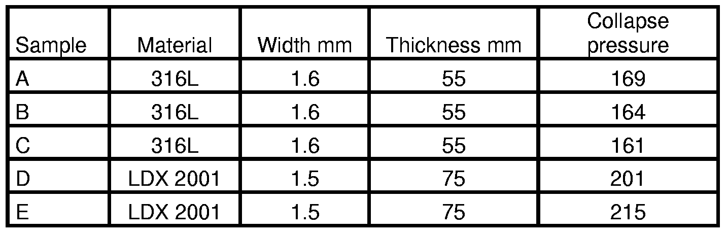
- the carcass was made from either 316L or LDX 2001 (Also called Lean Duplex).
- the carcass was made from folded and wound strips. Prior to folding the strips had the width and thickness as shown in table 2.
- Samples A, B and C were wound with a pitch of 19.1 mm.
- Samples D, E and F were wound with a pitch of 26.25 mm.
- the amount of steel material used for the carcass for samples D, E and F was about 7 % by weight less than the amount of steel material used for the samples A, B and C.
- the pipes were subjected to a collapse test, by inserting the samples into a pressure reactor so that the pipe ends were open to the atmosphere pressure.
- the pressure in the reactor was raised by about 15 bars/minute, until design pressure, which in this test was set to 100 bars.
- the pressure was held at 100 bars for 30 minutes. Thereafter the pressure was again continuously raised at a speed of 15 bars/minute until collapse of the pipe.
- the test temperature was 130 °C.
- the partial pressure of CO 2 was 15.5 bara, and the partial pressure of H 2 S was 0.1 bara. pH was calculated to 4.0 using NORSOK M-506.
- a glass lined autoclave with a total volume of 21.5 litres was used for the test.
- Specimens were cut in suitable lengths (5-12 cm) by use of a water-cooled cut-off wheel.
- the specimens were cleaned and degreased using the following procedure:
- test solution 15 litres was prepared in a 20 litre glass reaction vessel using:
- the glass reactor and the autoclave were connected.
- test solution was deaerated with industrial pure CO 2 from June 1 st 2004 to June 2 nd 2004.
- the autoclave and connection strings to the autoclave were evacuated four times in 30 minutes, and filled with CO 2 between evacuations. After the last evacuation the test solution was transferred to the autoclave by vacuum.
- test gas consisting of 0,64% by weight of H 2 S in CO 2 was used as test gas and bubbled through the test solution for 30 minutes at 13 barg.
- the autoclave was heated to a temperature of 130 °C, which was reached on June 4 th 2004 at 08:00.Test gas was bubbled through the test solution for 30 minutes at 17.3 barg, and the test time was started.
- the test temperature was 130 °C.
- the partial pressure of CO 2 was 3.1 bara, and the partial pressure of H 2 S was 0.02 bara. pH was calculated to 4.0 using NORSOK M-506.
- a glass lined autoclave with a total volume of 21.5 litres was used for the test.
- Specimens were cut in suitable lengths (5-12 cm) by use of a water-cooled cut-off wheel.
- the specimens were cleaned and degreased using the following procedure:
- test solution 15 litres was prepared in a 20 litre glass reaction vessel using:
- the glass reactor and the autoclave were connected.
- test solution was deaerated with industrial pure CO 2 from August 18 th 2004 to August 19 th 2004.
- the autoclave and connection strings to the autoclave were evacuated four times in 30 minutes, and filled with CO 2 between evacuations. After the last evacuation the test solution was transferred to the autoclave by vacuum.
- test gas consisting of 0.64% H 2 S in CO 2 was used as test gas and bubbled through the test solution for 30 minutes at 1.5 barg.
- the autoclave was heated to a temperature of 130 °C, which was reached on August 23 rd 2004 at 09:00.Test gas was bubbled through the test solution for 60 minutes at 4.8 barg, and the test time was started.
- the exposed specimens were inspected visually using a low-power binocular microscope. Any general or localised corrosion was reported. In addition specimens were weighted and the corrosion rate determined. The result is found in table 5.
- Appendix C contains pictures of typical discolouring observed.
Landscapes
- Engineering & Computer Science (AREA)
- Mechanical Engineering (AREA)
- Chemical & Material Sciences (AREA)
- General Engineering & Computer Science (AREA)
- Materials Engineering (AREA)
- Metallurgy (AREA)
- Organic Chemistry (AREA)
- Rigid Pipes And Flexible Pipes (AREA)
- Heat Treatment Of Steel (AREA)
- Compositions Of Macromolecular Compounds (AREA)
Abstract
Description


Claims
Priority Applications (4)
| Application Number | Priority Date | Filing Date | Title |
|---|---|---|---|
| EP06706140.8A EP1929058B1 (en) | 2005-03-18 | 2006-03-14 | Use of a steel composition for the production of an armouring layer of a flexible pipe and the flexible pipe |
| US11/886,647 US7923126B2 (en) | 2005-03-18 | 2006-03-14 | Use of a steel composition for the production of an armouring layer of a flexible pipe and the flexible pipe |
| NO20075307A NO345983B1 (en) | 2005-03-18 | 2006-03-14 | Use of a steel mixture for the production of a reinforcing layer for a flexible rudder and the flexible rudder |
| BRPI0608627A BRPI0608627B1 (en) | 2005-03-18 | 2006-03-14 | uses a duplex steel, and flexible tubing |
Applications Claiming Priority (2)
| Application Number | Priority Date | Filing Date | Title |
|---|---|---|---|
| DKPA200500397 | 2005-03-18 | ||
| DKPA200500397 | 2005-03-18 |
Publications (2)
| Publication Number | Publication Date |
|---|---|
| WO2006097112A2 true WO2006097112A2 (en) | 2006-09-21 |
| WO2006097112A3 WO2006097112A3 (en) | 2008-05-02 |
Family
ID=34978665
Family Applications (1)
| Application Number | Title | Priority Date | Filing Date |
|---|---|---|---|
| PCT/DK2006/050007 Ceased WO2006097112A2 (en) | 2005-03-18 | 2006-03-14 | Use of a steel composition for the production of an armouring layer of a flexible pipe and the flexible pipe |
Country Status (5)
| Country | Link |
|---|---|
| US (1) | US7923126B2 (en) |
| EP (1) | EP1929058B1 (en) |
| BR (1) | BRPI0608627B1 (en) |
| NO (1) | NO345983B1 (en) |
| WO (1) | WO2006097112A2 (en) |
Cited By (14)
| Publication number | Priority date | Publication date | Assignee | Title |
|---|---|---|---|---|
| WO2008116469A1 (en) * | 2007-03-23 | 2008-10-02 | Nkt Flexibles I/S | A method of welding duplex stainless steel strip for the production of an armouring layer of a flexible pipe |
| FR2934349A1 (en) * | 2008-07-28 | 2010-01-29 | Technip France | FLEXIBLE CONDUIT FOR TRANSPORTING HYDROCARBONS WITH HIGH CORROSION RESISTANCE AND METHOD OF MANUFACTURING THE SAME |
| EP2228578A1 (en) | 2009-03-13 | 2010-09-15 | NV Bekaert SA | High nitrogen stainless steel wire for flexible pipe |
| FR2945099A1 (en) * | 2009-05-04 | 2010-11-05 | Technip France | PROCESS FOR MANUFACTURING A FLEXIBLE TUBULAR PIPE OF LARGE LENGTH |
| WO2011027154A1 (en) * | 2009-09-02 | 2011-03-10 | Genesis Oil & Gas Consultants Limited | Method of testing an unbonded flexible pipeline |
| WO2012097817A1 (en) | 2011-01-20 | 2012-07-26 | National Ollwell Varco Denmark I/S | An unbonded flexible pipe |
| WO2012131315A1 (en) * | 2011-03-25 | 2012-10-04 | Wellstream International Limited | Flexible pipe body and method of producing same |
| EP2593701A4 (en) * | 2010-07-14 | 2014-02-26 | Nat Oilwell Varco Denmark Is | An unbonded flexible pipe |
| EP2513543A4 (en) * | 2009-12-15 | 2016-03-02 | Nat Oilwell Varco Denmark Is | FLEXIBLE PIPE, NOT FASTENED |
| WO2016043936A1 (en) * | 2014-09-17 | 2016-03-24 | Exxonmobil Upstream Research Company | Flexible pipe with corrosion resistant layer |
| US9395022B2 (en) | 2010-05-12 | 2016-07-19 | National Oilwell Varco Denmark I/S | Unbonded flexible pipe |
| US9458956B2 (en) | 2011-01-20 | 2016-10-04 | National Oilwell Varco Denmark I/S | Flexible armored pipe |
| US9562633B2 (en) | 2009-10-28 | 2017-02-07 | National Oilwell Varco Denmark I/S | Flexible pipe and a method of producing a flexible pipe |
| US10197198B2 (en) | 2014-03-21 | 2019-02-05 | National Oilwell Varco Denmark I/S | Flexible pipe |
Families Citing this family (5)
| Publication number | Priority date | Publication date | Assignee | Title |
|---|---|---|---|---|
| BR112013032388B1 (en) * | 2011-06-17 | 2020-09-29 | National Oilwell Varco Denmark I / S | FLEXIBLE TUBE NOT UNITED FOR APPLICATIONS OUTSIDE THE COAST AND USE OF MANGANESE STEEL |
| UA111115C2 (en) | 2012-04-02 | 2016-03-25 | Ейкей Стіл Пропертіс, Інк. | cost effective ferritic stainless steel |
| CN106090462A (en) * | 2016-08-17 | 2016-11-09 | 河北派润建筑工程有限公司 | Resinous coat steel strand wires strengthen steel pipe and pipeline |
| US10935168B2 (en) * | 2017-11-29 | 2021-03-02 | Polyflow Llc | Spoolable reinforced thermoplastic pipe for subsea and buried applications |
| AU2020393954A1 (en) * | 2019-11-25 | 2022-06-02 | National Oilwell Varco Denmark I/S | An unbonded flexible pipe |
Citations (5)
| Publication number | Priority date | Publication date | Assignee | Title |
|---|---|---|---|---|
| FR2764669A1 (en) | 1997-06-13 | 1998-12-18 | Coflexip | METHOD FOR MANUFACTURING A FLEXIBLE PIPE |
| WO2002027056A1 (en) | 2000-09-27 | 2002-04-04 | Avestapolarit Aktiebolag (Publ) | Ferritic-austenitic stainless steel |
| US6408891B1 (en) | 1998-02-18 | 2002-06-25 | Institut Francais Du Petrole | Flexible pipe for static use in a corrosive ambience |
| US20040050442A1 (en) | 2000-10-10 | 2004-03-18 | Kristian Glejbol | Armoured, flexible pipe |
| WO2004079028A1 (en) | 2003-03-02 | 2004-09-16 | Sandvik Intellectual Property Ab | Duplex stainless steel alloy and use thereof |
Family Cites Families (20)
| Publication number | Priority date | Publication date | Assignee | Title |
|---|---|---|---|---|
| DE3409734A1 (en) * | 1984-03-20 | 1985-09-26 | The Furukawa Electric Co., Ltd., Tokio/Tokyo | BENDING PIPELINE FOR THE TRANSPORT OF FLOWING MEDIA |
| US6065501A (en) | 1989-06-30 | 2000-05-23 | Institute Francais Du Petrole | Flexible tube having at least one elongated reinforcing element with a T-shaped profile |
| US5645109A (en) | 1990-06-29 | 1997-07-08 | Coflexip | Flexible tubular pipe comprising an interlocked armoring web and process for producing it |
| FR2727738A1 (en) | 1994-12-05 | 1996-06-07 | Coflexip | FLEXIBLE TUBULAR DRIVING COMPRISING A STAPLEED ARMOR PATCH |
| FR2743858B1 (en) * | 1996-01-22 | 1998-02-13 | Coflexip | USE OF A BONDED FLEXIBLE DUCT |
| FR2752904B1 (en) * | 1996-08-27 | 1998-10-16 | Coflexip | METHOD FOR MANUFACTURING A FLEXIBLE PIPE |
| US5730188A (en) | 1996-10-11 | 1998-03-24 | Wellstream, Inc. | Flexible conduit |
| FR2756358B1 (en) * | 1996-11-22 | 1999-01-29 | Inst Francais Du Petrole | SHEATH WITH LIMITED PERMEABILITY AND APPLICATION TO PRESSURE PIPES |
| FR2775052B1 (en) | 1998-02-18 | 2000-03-10 | Coflexip | FLEXIBLE PIPE FOR RISING COLUMN IN A SEA OIL EXPLOITATION |
| FR2780482B1 (en) | 1998-06-30 | 2000-07-21 | Coflexip | METHOD FOR MANUFACTURING A METAL CARCASS FOR FLEXIBLE OR OMBILICAL PIPING |
| FR2782141B1 (en) * | 1998-08-10 | 2000-09-08 | Coflexip | RESISTANT FLEXIBLE PIPE WITH LIMITING LEAKAGE OF THE SEALING SHEATH |
| ATE261563T1 (en) | 1998-12-16 | 2004-03-15 | Nkt Flexibles Is | REINFORCED FLEXIBLE PIPE AND ITS APPLICATION |
| FR2802607B1 (en) | 1999-12-15 | 2002-02-01 | Inst Francais Du Petrole | FLEXIBLE PIPE COMPRISING LOW CARBON STEEL WEAPONS |
| DK200000242A (en) | 2000-02-16 | 2001-01-18 | Nkt Flexibles Is | Flexible reinforced pipeline, as well as the use of the same |
| FR2808070B1 (en) * | 2000-04-21 | 2002-06-07 | Coflexip | FLEXIBLE METAL TUBE WITH BOX AND FLEXIBLE CONDUIT COMPRISING SUCH A METAL TUBE |
| DK200001707A (en) | 2000-04-25 | 2000-11-15 | Nkt Flexibles Is | Reinforced flexible pipe and use of the same |
| US6691743B2 (en) * | 2000-05-10 | 2004-02-17 | Coflexip | Flexible pipe with wire or strip winding for maintaining armours |
| FR2817318B1 (en) | 2000-11-24 | 2002-12-27 | Coflexip | FLEXIBLE TUBULAR CONDUCT |
| FR2837898B1 (en) | 2002-03-28 | 2004-07-16 | Coflexip | FLEXIBLE TUBULAR PIPE WITH POLYMERIC SHEATH IN ELASTOMERIC THERMOPLASTIC POLYMER |
| EP1579141B1 (en) | 2002-11-29 | 2011-08-17 | NKT Flexibles I/S | A flexible pipe connected to an end fitting |
-
2006
- 2006-03-14 US US11/886,647 patent/US7923126B2/en active Active
- 2006-03-14 EP EP06706140.8A patent/EP1929058B1/en not_active Revoked
- 2006-03-14 WO PCT/DK2006/050007 patent/WO2006097112A2/en not_active Ceased
- 2006-03-14 NO NO20075307A patent/NO345983B1/en unknown
- 2006-03-14 BR BRPI0608627A patent/BRPI0608627B1/en not_active IP Right Cessation
Patent Citations (5)
| Publication number | Priority date | Publication date | Assignee | Title |
|---|---|---|---|---|
| FR2764669A1 (en) | 1997-06-13 | 1998-12-18 | Coflexip | METHOD FOR MANUFACTURING A FLEXIBLE PIPE |
| US6408891B1 (en) | 1998-02-18 | 2002-06-25 | Institut Francais Du Petrole | Flexible pipe for static use in a corrosive ambience |
| WO2002027056A1 (en) | 2000-09-27 | 2002-04-04 | Avestapolarit Aktiebolag (Publ) | Ferritic-austenitic stainless steel |
| US20040050442A1 (en) | 2000-10-10 | 2004-03-18 | Kristian Glejbol | Armoured, flexible pipe |
| WO2004079028A1 (en) | 2003-03-02 | 2004-09-16 | Sandvik Intellectual Property Ab | Duplex stainless steel alloy and use thereof |
Cited By (25)
| Publication number | Priority date | Publication date | Assignee | Title |
|---|---|---|---|---|
| WO2008116469A1 (en) * | 2007-03-23 | 2008-10-02 | Nkt Flexibles I/S | A method of welding duplex stainless steel strip for the production of an armouring layer of a flexible pipe |
| US8350178B2 (en) | 2007-03-23 | 2013-01-08 | National Oilwell Varco Denmark I/S | Method of welding duplex stainless steel strip for the production of an armouring layer of a flexible pipe |
| FR2934349A1 (en) * | 2008-07-28 | 2010-01-29 | Technip France | FLEXIBLE CONDUIT FOR TRANSPORTING HYDROCARBONS WITH HIGH CORROSION RESISTANCE AND METHOD OF MANUFACTURING THE SAME |
| WO2010012896A1 (en) | 2008-07-28 | 2010-02-04 | Technip France | Flexible duct for conveying hydrocarbons having a high corrosion resistance, and method for making same |
| US9341288B2 (en) | 2008-07-28 | 2016-05-17 | Technip France | Flexible pipe for conveying hydrocarbons having a high corrosion resistance, and method for making same |
| AU2009275782B2 (en) * | 2008-07-28 | 2015-09-10 | Technip France | Flexible pipe for conveying hydrocarbons having a high corrosion resistance, and method for making same |
| EP2228578A1 (en) | 2009-03-13 | 2010-09-15 | NV Bekaert SA | High nitrogen stainless steel wire for flexible pipe |
| FR2945099A1 (en) * | 2009-05-04 | 2010-11-05 | Technip France | PROCESS FOR MANUFACTURING A FLEXIBLE TUBULAR PIPE OF LARGE LENGTH |
| WO2010128238A1 (en) | 2009-05-04 | 2010-11-11 | Technip France | Method for making a flexible tubular pipe having a long length |
| GB2481175A (en) * | 2009-05-04 | 2011-12-14 | Technip France | Method for making a flexible tubular pipe having a long length |
| DK179251B1 (en) * | 2009-05-04 | 2018-03-05 | Technip France | Method for making a flexible tubular pipe having a long length |
| GB2481175B (en) * | 2009-05-04 | 2014-02-19 | Technip France | Method for making a flexible tubular pipe having a long length |
| WO2011027154A1 (en) * | 2009-09-02 | 2011-03-10 | Genesis Oil & Gas Consultants Limited | Method of testing an unbonded flexible pipeline |
| US9562633B2 (en) | 2009-10-28 | 2017-02-07 | National Oilwell Varco Denmark I/S | Flexible pipe and a method of producing a flexible pipe |
| EP2513543A4 (en) * | 2009-12-15 | 2016-03-02 | Nat Oilwell Varco Denmark Is | FLEXIBLE PIPE, NOT FASTENED |
| US9395022B2 (en) | 2010-05-12 | 2016-07-19 | National Oilwell Varco Denmark I/S | Unbonded flexible pipe |
| EP2593701A4 (en) * | 2010-07-14 | 2014-02-26 | Nat Oilwell Varco Denmark Is | An unbonded flexible pipe |
| US9188254B2 (en) | 2011-01-20 | 2015-11-17 | National Oilwell Varco Denmark I/S | Unbonded flexible pipe |
| US9458956B2 (en) | 2011-01-20 | 2016-10-04 | National Oilwell Varco Denmark I/S | Flexible armored pipe |
| WO2012097817A1 (en) | 2011-01-20 | 2012-07-26 | National Ollwell Varco Denmark I/S | An unbonded flexible pipe |
| WO2012131315A1 (en) * | 2011-03-25 | 2012-10-04 | Wellstream International Limited | Flexible pipe body and method of producing same |
| US10030793B2 (en) | 2011-03-25 | 2018-07-24 | Ge Oil & Gas Uk Limited | Flexible pipe body and method of producing same |
| US10197198B2 (en) | 2014-03-21 | 2019-02-05 | National Oilwell Varco Denmark I/S | Flexible pipe |
| WO2016043936A1 (en) * | 2014-09-17 | 2016-03-24 | Exxonmobil Upstream Research Company | Flexible pipe with corrosion resistant layer |
| US10207455B2 (en) | 2014-09-17 | 2019-02-19 | Exxonmobil Upstream Research Company | Flexible pipe with corrosion resistant layer |
Also Published As
| Publication number | Publication date |
|---|---|
| US20090218093A1 (en) | 2009-09-03 |
| NO20075307L (en) | 2007-10-17 |
| US7923126B2 (en) | 2011-04-12 |
| EP1929058A2 (en) | 2008-06-11 |
| NO345983B1 (en) | 2021-12-06 |
| BRPI0608627B1 (en) | 2016-03-29 |
| EP1929058B1 (en) | 2017-09-27 |
| WO2006097112A3 (en) | 2008-05-02 |
| BRPI0608627A2 (en) | 2010-11-30 |
Similar Documents
| Publication | Publication Date | Title |
|---|---|---|
| US7923126B2 (en) | Use of a steel composition for the production of an armouring layer of a flexible pipe and the flexible pipe | |
| US10001228B2 (en) | Unbonded flexible pipe | |
| US9803267B2 (en) | Austenitic stainless steel | |
| RU2247171C2 (en) | Ferrite-austenite alloy and method of manufacturing pipes therefrom | |
| CN102869803B (en) | High-strength stainless steel for oil wells and high-strength stainless steel pipes for oil wells | |
| EP2562284B1 (en) | Cr-CONTAINING STEEL PIPE FOR LINE PIPE AND HAVING EXCELLENT INTERGRANULAR STRESS CORROSION CRACKING RESISTANCE AT WELDING-HEAT-AFFECTED PORTION | |
| WO2011065582A1 (en) | Welded steel pipe for linepipe with superior compressive strength and excellent sour resistance, and process for producing same | |
| CN111868278B (en) | Corrosion resistant duplex stainless steel | |
| WO2001010591A1 (en) | Martensite stainless steel welded steel pipe | |
| AU2012259511A1 (en) | Austenitic stainless steel | |
| WO2012111537A1 (en) | Duplex stainless steel | |
| AU2005301376A1 (en) | Duplex stainless steel | |
| WO2013035588A1 (en) | Two-phase stainless steel | |
| JP2001279392A (en) | Martensitic stainless steel and manufacturing method | |
| JP5786351B2 (en) | Steel pipe for line pipes with excellent anti-collapse performance | |
| EP2228578A1 (en) | High nitrogen stainless steel wire for flexible pipe | |
| JP5045178B2 (en) | Method for manufacturing bend pipe for line pipe and bend pipe for line pipe | |
| JP2001220653A (en) | Martensitic stainless steel with excellent fatigue resistance and tube making method from it | |
| WO2013161089A1 (en) | Cr-CONTAINING STEEL PIPE FOR LINEPIPE EXCELLENT IN INTERGRANULAR STRESS CORROSION CRACKING RESISTANCE OF WELDED HEAT AFFECTED ZONE | |
| JP2575250B2 (en) | Line pipe with excellent corrosion resistance and weldability |
Legal Events
| Date | Code | Title | Description |
|---|---|---|---|
| REEP | Request for entry into the european phase |
Ref document number: 2006706140 Country of ref document: EP |
|
| WWE | Wipo information: entry into national phase |
Ref document number: 2006706140 Country of ref document: EP |
|
| NENP | Non-entry into the national phase |
Ref country code: DE |
|
| NENP | Non-entry into the national phase |
Ref country code: RU |
|
| WWW | Wipo information: withdrawn in national office |
Ref document number: RU |
|
| WWE | Wipo information: entry into national phase |
Ref document number: 11886647 Country of ref document: US |
|
| WWP | Wipo information: published in national office |
Ref document number: 2006706140 Country of ref document: EP |
|
| ENP | Entry into the national phase |
Ref document number: PI0608627 Country of ref document: BR Kind code of ref document: A2 Effective date: 20070918 |
|
| WWW | Wipo information: withdrawn in national office |
Ref document number: 2006706140 Country of ref document: EP |