WO2006106975A1 - 経編地及びその製造方法 - Google Patents
経編地及びその製造方法 Download PDFInfo
- Publication number
- WO2006106975A1 WO2006106975A1 PCT/JP2006/306947 JP2006306947W WO2006106975A1 WO 2006106975 A1 WO2006106975 A1 WO 2006106975A1 JP 2006306947 W JP2006306947 W JP 2006306947W WO 2006106975 A1 WO2006106975 A1 WO 2006106975A1
- Authority
- WO
- WIPO (PCT)
- Prior art keywords
- knitted fabric
- knitted
- warp
- fabric portion
- knitting
- Prior art date
- Legal status (The legal status is an assumption and is not a legal conclusion. Google has not performed a legal analysis and makes no representation as to the accuracy of the status listed.)
- Ceased
Links
Classifications
-
- D—TEXTILES; PAPER
- D04—BRAIDING; LACE-MAKING; KNITTING; TRIMMINGS; NON-WOVEN FABRICS
- D04B—KNITTING
- D04B21/00—Warp knitting processes for the production of fabrics or articles not dependent on the use of particular machines; Fabrics or articles defined by such processes
- D04B21/20—Warp knitting processes for the production of fabrics or articles not dependent on the use of particular machines; Fabrics or articles defined by such processes specially adapted for knitting articles of particular configuration
- D04B21/207—Wearing apparel or garment blanks
-
- D—TEXTILES; PAPER
- D04—BRAIDING; LACE-MAKING; KNITTING; TRIMMINGS; NON-WOVEN FABRICS
- D04B—KNITTING
- D04B21/00—Warp knitting processes for the production of fabrics or articles not dependent on the use of particular machines; Fabrics or articles defined by such processes
-
- D—TEXTILES; PAPER
- D10—INDEXING SCHEME ASSOCIATED WITH SUBLASSES OF SECTION D, RELATING TO TEXTILES
- D10B—INDEXING SCHEME ASSOCIATED WITH SUBLASSES OF SECTION D, RELATING TO TEXTILES
- D10B2403/00—Details of fabric structure established in the fabric forming process
- D10B2403/03—Shape features
- D10B2403/033—Three dimensional fabric, e.g. forming or comprising cavities in or protrusions from the basic planar configuration, or deviations from the cylindrical shape as generally imposed by the fabric forming process
- D10B2403/0333—Three dimensional fabric, e.g. forming or comprising cavities in or protrusions from the basic planar configuration, or deviations from the cylindrical shape as generally imposed by the fabric forming process with tubular portions of variable diameter or distinct axial orientation
-
- D—TEXTILES; PAPER
- D10—INDEXING SCHEME ASSOCIATED WITH SUBLASSES OF SECTION D, RELATING TO TEXTILES
- D10B—INDEXING SCHEME ASSOCIATED WITH SUBLASSES OF SECTION D, RELATING TO TEXTILES
- D10B2501/00—Wearing apparel
- D10B2501/02—Underwear
- D10B2501/021—Hosiery; Panti-hose
Definitions
- the present invention relates to a warp knitted fabric and a method for producing the same, and more particularly to a warp knitted fabric capable of providing a product having excellent dimensional stability and shape stability by improving processing stability. It relates to the manufacturing method.
- Patent Document 1 a tubular knitted fabric is continuously knitted by warp knitting, and a part of a knitted fabric of a fixed length unit is finally formed from a product. A narrow knitted fabric part force that becomes a discarded part to be separated A warp knitted fabric formed separately from the knitted fabric on the left and right sides is disclosed.
- warp knitted fabrics especially those using heat-shrinkable synthetic fibers such as polyester and nylon for knitting yarns, the shape and dimensional stability can be improved by heat setting and other processes when manufacturing products. It is necessary to improve.
- Patent Document 1 Japanese Patent No. 3480917
- a warp knitted fabric having a part (separation part) connected to other parts, such as the one described above, has a left and right knitting of the unconnected parts. Since the end of the ground portion becomes a free end, when heated for heat setting or the like, the knitted fabric portion shrinks and deforms, and there is a possibility that a desired size and shape cannot be obtained.
- the present invention aims to provide a warp knitted fabric and a method for manufacturing the warp knitted fabric that can solve such problems and obtain a warp knitted product having excellent shape and dimensional stability.
- the present invention provides:
- a knitted fabric portion that becomes a product in a predetermined pattern is knitted together with a peripheral knitted fabric portion that is finally separated from the knitted fabric portion, and a knitted fabric end of the knitted fabric portion and a peripheral knitted fabric adjacent thereto.
- it is a warp knitted fabric characterized by being knitted at intervals of 2 to 50 courses.
- a knitted fabric portion that becomes a product in a predetermined pattern is knitted together with a peripheral knitted fabric portion that is finally separated from the knitted fabric portion, and a knitted fabric end of the knitted fabric portion
- the knitted warp knitted fabric is knitted by connecting the knitted warp knitted fabric with the peripheral knitted knitted fabric adjacent to each other by the hand knitted knitted fabric knitted with a predetermined interval in the warp direction.
- the warp knitted fabric is produced by knitting with a length of 2 to 20 courses at intervals of 2 to 50 courses in the warp direction.
- the knitted fabric portion knitted only a part of the knitting yarn knitting the knitted fabric portion, the knitted fabric end of the knitted fabric portion and the peripheral knitted fabric portion.
- the method for producing a warp knitted fabric according to (6) characterized in that the knitting is performed over the ground edge.
- FIG. 12 shows a conventional example in which a knitted fabric portion by warp knitting is continuously knitted in a pants shape, and finally is separated from a product into a part of a knitted fabric of a certain length unit.
- the partial force that becomes the discarded portion 13 is formed separately from the leg tubular knitted fabric portion 14 that is a part of the knitted fabric portion 11 on the left and right sides thereof.
- 19 shows the separation part.
- the upper end of the abandoned portion 13 is continuously knitted by the knitted fabric portion 11 and the front / back knot portion 15 connecting the front and back knitted fabrics, and the lower end is a repeat cut line 16 with the knitted fabric portion of the pattern of another product 1 unit. It is continuously organized in the part.
- FIG. 1 shows an example in which a knitted fabric portion is continuously knitted in a pant-like pattern as an example of a warp knitted fabric according to the present invention.
- a cylindrical knitted fabric portion 1 that becomes a product with a predetermined pant-like pattern is knitted by warp knitting, and at the same time, a part of the knitted fabric with a length of 1 product is finally formed.
- the discarded portion 3 that is a peripheral knitted fabric portion separated from the knitted fabric portion 1 that becomes a product is formed, and is adjacent to the left and right of the discarded portion 3 and corresponds to the pants crotch portion of the knitted fabric portion 1
- Main partial force Continuous leg knitted fabric parts 4, 4 are formed on both sides.
- the knitted fabric portion 2 knitted at a predetermined interval in the warp direction (well direction), that is, the knitted fabric end 3a of the discard portion 3 and the leg tubular knitted fabric portion 4 Wrapping with yarn across both ends of knitted fabric 4a It is connected by the knitted fabric part 2.
- the upper end of the discard part 3 is continuously knitted with the knitted fabric part 1 at the front and back knot parts 5, and the lower end of the discard part 3 is knitted with the knitted fabric part 1 in a pattern of another product. It is continuously knitted on the part of the repeat cut line 6 between.
- the discard section 3 may be knitted separately for the front and back tissues, or may be knitted into a single fabric.
- the front and back knot parts 5 at the upper end of the discard part 3 are knotted on the front and back knitted fabrics, and need not be sewn in a state where the discard part 3 is separated and removed!
- this warp knitted fabric does not have a free end between the foot tubular knitted fabric portion 4 and the discarding portion 3, a synthetic fiber having a heat-shrinkable property such as polyester or nylon as a knitting yarn.
- a synthetic fiber having a heat-shrinkable property such as polyester or nylon as a knitting yarn.
- it is set in a predetermined pattern shape and will not be deformed into irregular shapes.
- heat setting the product can be prevented from being extremely shrunk or deformed by washing or ironing after it has become the final product, so that it can maintain a predetermined size and shape. Occurrence of sag and slack is also suppressed, and the texture when worn can be maintained.
- FIG. 2 shows the warp knitted fabric of Fig. 1 cut into patterns for one unit of product.
- FIG. 3 shows a product obtained by separating and removing the waste part 3 from FIG.
- the knitted fabric portion 1 that becomes a product in a predetermined pattern is knitted by warp knitting, and the knitted fabric ends along the wel direction of the knitted fabric portion 1, for example, both sides
- the knitted fabric end 3a is connected to the knitted fabric portion 2 with a predetermined interval in the warp direction.
- the knitted fabric portion 1 is connected to the peripheral knitted fabric portion such as the discarding portion 3 or the like. Uniformity is achieved throughout the ground, and deformation and wrinkles due to partial shrinkage of the knitted fabric portion 1 are suppressed, and the size is easily stabilized. Therefore, products with excellent tactile sensation can be obtained with good yield.
- the front and back knitted fabrics of the tubular knitted fabric portion 1 are knitted, for example, with respect to the passing knitted fabric portion 2 in the warp knitted fabric of the present invention.
- the foot tubular knitted fabric portion 4 forming a part of the knitted fabric portion 1 at a required portion with respect to a part of the knitting yarn to be processed 4
- the knitted fabric ends 4a and 3a are knitted to both the knitted fabric end 4a of the knitted fabric end 4a and the knitted fabric end 3a of the discarded portion 3 adjacent to the knitted fabric.
- the knitting yarn other than the yarn for knitting the stretch knitted fabric portion is knitted so that there is basically no span between the knitted fabric ends 4a, 3a. It is something to keep.
- the stretch knitted fabric portion 2 is preferably 2 to 20 courses, more preferably 2 to 16 courses in the warp direction (well direction). That is, when the length of the warp knitted fabric portion 2 in the warp direction is less than 2 courses, the shape and dimensional stability of the tubular knitted fabric portion 1 may be deteriorated. There is a risk that the stretch knitted fabric portion 2 will not be easily cut.
- the knitted fabric portion 2 is preferably knitted at intervals of 2 to 50 courses, more preferably 2 to 16 courses in the warp direction. In other words, if the distance is less than 2 courses, there is a risk that the distance between the connecting portions by passing will be shorter after cutting. In addition, if the interval is larger than 50 courses, the shape and dimensional stability of the product are deteriorated, and the product may not be finished in a predetermined shape.
- Fig. 10 (A) the length in the warp direction by one stretch knitted fabric portion 2, that is, the length in the warp direction of the connected portion is 3 courses, and the number of yarn stretches is Fig. 10 (B) shows the case where the length in the warp direction by one knitted fabric portion 2 is 4 courses, and the number of yarns delivered is 3, The case where the interval is 6 courses is shown.
- FIG. 4 shows an example in which the knitted fabric portion 1 is continuously knitted in a shirt-like pattern as another example of the warp knitted fabric according to the present invention.
- a cylindrical knitted fabric portion 1 that becomes a product with a predetermined shirt-like pattern is knitted, and the knitted fabric portion 1 is formed on a part of the knitted fabric having a length of one product.
- the narrow throw-away parts 3 and 3 which are the peripheral knitted fabric parts that are finally separated from the knitted fabric part 1 that becomes the product, are formed so as to form a knitted fabric part that becomes the body part 7 and both sleeve parts 8 and 8. Is formed.
- the knitted fabric ends along the wel direction on both the left and right sides of the discarded portion 3 and the knitted fabric ends along the wel direction of the body portion 7 and the sleeve portion 8 adjacent to the left and right are predetermined in the warp direction. They are connected by the knitted fabric part 2 which is knitted at intervals.
- the hand knitted fabric portion 2 is knitted in the same manner as in the above-described embodiment.
- the knitted fabric portion 1 is connected to the peripheral knitted fabric portion such as the discarding portion 3 or the like. Therefore, the shrinkage of the knitted fabric part 1 is made uniform throughout the knitted fabric during heat-set processing after knitting, etc., and deformation and wrinkles due to partial shrinkage are suppressed, and the size is stable. I'm going to be.
- Fig. 5 shows a product in which the warp knitted fabric of Fig. 4 is cut for each unit pattern of the product
- Fig. 6 shows a product in which the discard part 3 is cut off from Fig. 5 and removed.
- the warp knitted fabric of the present invention described above can be knitted by a double raschel knitting machine, particularly, a double raschel knitting machine having a jack heel illustrated in FIG.
- N1 and N2 are front and rear knitting needles, and many of them are arranged in a direction perpendicular to the paper surface of FIG. L-2, L-3, L-4, and L-5 indicate the rivets that guide the knitting yarn.
- the heels L-3 and L-4 are controlled by the jacquard mechanism.
- This jacquard kite is provided so that each guide for guiding yarn L-3a; L-4a can be displaced in the direction of one needle apart from the motion of the kite.
- This guide L-3a; L- The displacement of 4a is controlled by jacquard.
- FIG. 8 shows an example of the structure of the knitted fabric portion 1 of the present invention
- FIG. 9 shows an example of the structure of the interwoven knitted fabric portion 2 of the present invention.
- F represents a knitting course with a front knitting needle
- B represents a knitting course with a rear knitting needle
- the course of F! It shows that the front side knitted fabric (front side) is knitted with the 3 knitting yarns, and the back side knitted fabric (rear side) is knitted with the knitting yarns of L-5 and L-4 on the course B.
- the tubular knitted fabric portion is knitted into a tubular shape by joining the front knitted fabric and the back knitted fabric by a method such as binding knitting at both side edge portions (not shown).
- the knitted fabric portion 2 in the present invention is a part of the ground organization of the front and back knitted fabrics as illustrated in the organization of FIG. While knitting the ground structure of the front and back knitted fabric with the yarn guided by 4 and the yarn guided by ⁇ L-2; L-5, among the yarns of ⁇ L-3; L-4
- the yarns arranged at the knitted fabric end (pattern end) of the knitted fabric portion 1 and the knell at the Z or the knitted fabric end of the peripheral knitted fabric portion are respectively arranged at predetermined intervals in the warp direction.
- the knitted fabric ends of the two knitted fabric portions are knitted with a jacquard action by extra displacement in the weft direction by one stitch and passing it to the knitted fabric end of the adjacent knitted fabric portion.
- the knitted fabric part That is, in the knitting of the course of F3, the yarn of the heel L 3 is knitted in the front side ground texture, and at the same time, the yarn at the end of the knitted fabric, that is, the end of the pattern is further displaced to the adjacent knitting needle. By doing so, the sinker loop portion thereby knitted the knitted fabric portion connecting the knitted fabric ends of the two knitted fabric portions to each other. Also, even if you go to the F7 course!
- the edge of the knitted fabric that is the end of the pattern of part 1 and the edge of the knitted fabric of the peripheral knitted fabric part the whole knitted fabric is connected.
- uniformly heat-treating it can be finished to a predetermined shape and size.
- the knitted fabric portion 2 is knitted so as to connect the tubular knitted fabric portion and its peripheral knitted fabric portion at a predetermined length and interval in the warp direction (well direction). It can be easily cut and removed after processing, and the quality of the pattern knitted fabric is hardly impaired.
- the pattern of the knitted fabric portion 1 is repeatedly knitted repeatedly at regular intervals corresponding to the length of one unit of product. By continuously knitting in the warp direction in this way, the fabric cutting loss can be reduced.
- the continuous knitted fabric 1A in which the pattern of the knitted fabric portion 1 is continuously knitted in the warp direction, is connected in parallel in the width direction and knitted by knitting. It is preferable because it can be efficiently knitted.
- each of the continuous knitted fabrics 1A in a plurality of rows becomes a peripheral knitted fabric portion where other adjacent continuous knitted fabrics 1A are separated after knitting. Therefore, the sequence of adjacent columns Even in the connection between the sequels 1A and 1A, the knitted fabric portion knitted by passing a part of the knitting yarn to the ends of the knitted fabric at a predetermined interval in the warp direction (well direction) 2 can be linked together.
- the knitting method described above is not limited to the illustrated pant shape or shirt shape, and other warp knitted fabrics for obtaining various warp knitted products such as those used for seat covers and bags, as well as other apparel applications. There is no particular limitation.
- the pattern refers to the final knitting of clothes such as shirts, knots, skirts, and pouches, knocks, and the like, for example, by a warp knitting machine having a jacquard mechanism, for example, a double raschel knitting machine. Say the form of the product.
- the end edge knitted fabric portion includes an end edge portion along the wel direction of the pattern of the knitted fabric portion to be a product, and an end edge portion along the wel direction of the peripheral knitted fabric portion adjacent thereto.
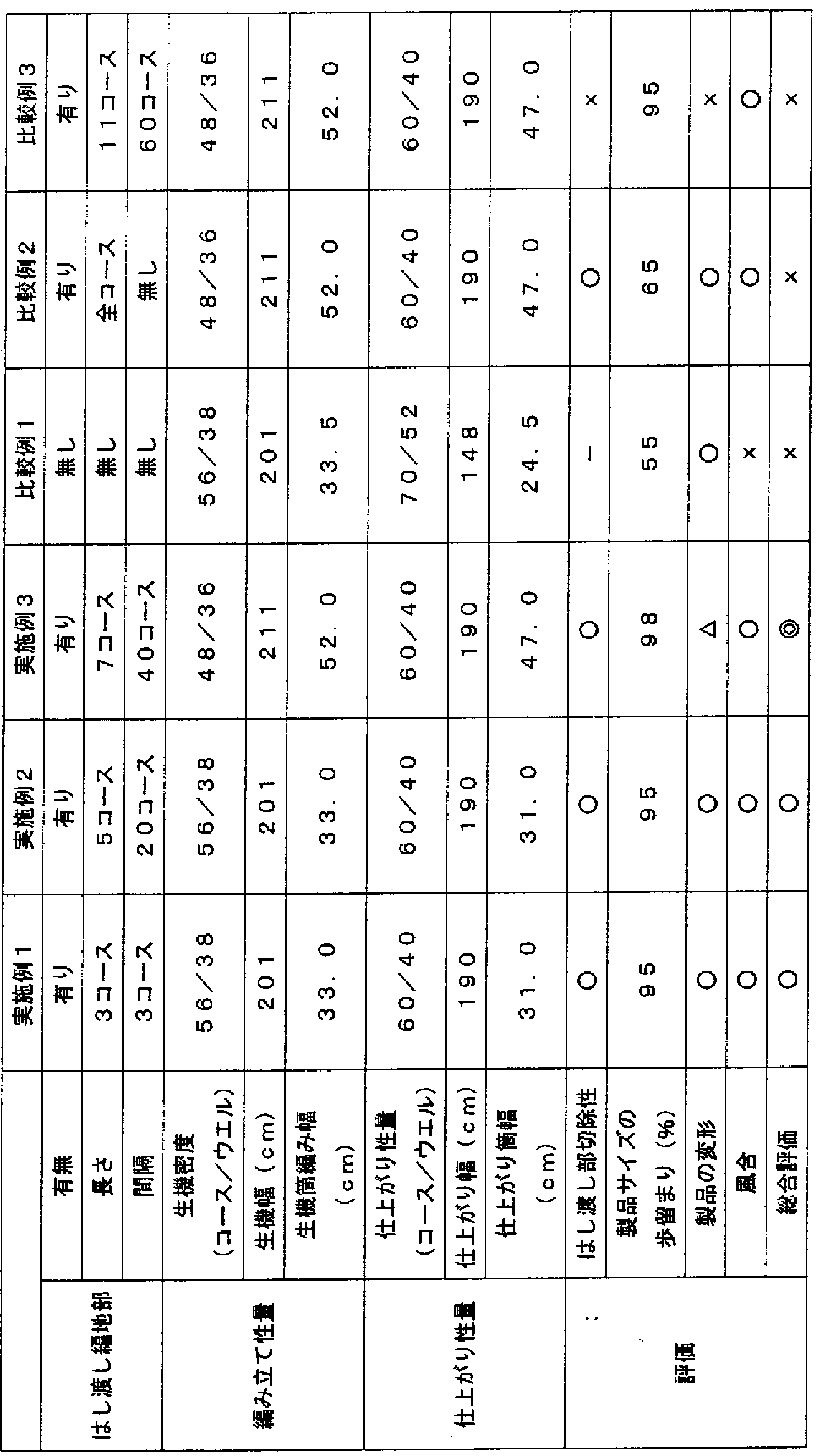
- the knitted fabric portion that connects the knitted fabric portion that becomes the product and the knitted fabric (peripheral knitted fabric portion) that becomes the discarding portion is made to pass the sinker loop at intervals of 3 courses in the warp direction (well direction).
- the knitted fabric was knitted with a length of 3 courses (2 sinker loops) in the warp knitted fabric section.
- the obtained knitted fabric was scoured at 60 ° C and then subjected to tentering heat setting (180 ° C) to obtain pants of 60 course Z ⁇ and 40 well Z ⁇ .
- Table 1 shows the properties and evaluation.
- the L-2 and L-5 have a 67dtex50f polyester.
- the density of the raw machine was 50 course Z34 uel.
- the knitted fabric portion that connects the knitted fabric portion that becomes the product and the knitted fabric (peripheral knitted fabric portion) that becomes the discarding portion is made to pass the sinker loop at intervals of 20 courses in the warp direction (well direction).
- the knitted fabric part was knitted with a length of 5 courses (4 sinker loops).
- the polyester yarn of 67dtex50f is used for L-2 and L-5. 4 to 5 using a covered yarn with a single force burred on a L-3 and L-4 jacquard with 78dtex36f polyester yarn and 44dtex polyurethane elastic yarn with a covering number of 500TZm.
- the warp knitted fabric of the shirt pattern was knitted. The density of the raw machine was 48 course Z36 uel.
- the knitted fabric part that connects the knitted fabric part that becomes the product and the knitted fabric (peripheral knitted fabric part) that becomes the throw-away part of the armpits so that the sinker loop is passed at intervals of 40 courses in the course direction.
- the knitted fabric was knitted with a length of 7 courses (6 sinker loops).
- the knitted fabric portions were knitted in a separated state without being connected to each other, and only the upper and lower ends were knitted so as to be continuous with the knitted fabric portion.
- polyester yarn of 67dtex50f is used for ⁇ L-2 and L-5.
- polyester yarn of 67dtex50f is used for ⁇ L-2 and L-5.
- a warp knitted fabric with a shirt pattern was knitted as shown in ⁇ 5.
- the density of the raw machine was 48 course Z36 uel.
- the sinker loop is passed across the entire course (each course) without any interval in the warp direction (well direction).
- the left and right stretch knitted fabric that connects the tubular knitted fabric portion that is the product and the peripheral knitted fabric portion that is the throw-away portion of the armpits has a sinker loop at 60 course intervals in the warp direction (well direction).
- the knitted fabric was knitted with a length of 11 courses (10 sinker loops).
- FIG. 1 is a schematic view of a knitted state of an example of a warp knitted fabric of a pant pattern of the present invention.
- FIG. 2 is a schematic view of the pattern of FIG. 1 cut along a repeat line.
- FIG. 3 is a schematic view of the final product of the pants made of the same warp knitted fabric.
- FIG. 4 is a schematic view of a knitted state of an example of a warp knitted fabric of a shirt pattern of the present invention.
- FIG. 5 is a schematic diagram of the shirt pattern of FIG. 4 cut along a repeat line.
- FIG. 6 A schematic view of the final product of the shirt composed of the above warp knitted fabric.
- FIG. 7 is a schematic view of the main part of a double raschel machine.
- FIG. 8 is a diagram showing an example of a structure of a knitted fabric portion in a warp knitted fabric of the present invention.
- FIG. 9 is a diagram showing an example of a structure of a knitted fabric portion in a warp knitted fabric of the present invention.
- FIG. 10 is a conceptual diagram showing two examples of a knitted fabric portion in a warp knitted fabric of the present invention.
- FIG. 11 is a schematic view in which a plurality of patterns are knitted in the width direction of the warp knitted fabric of the present invention.
- FIG. 12 is a schematic diagram of a knitting state of an example of a warp knitted fabric of a conventional pant pattern.
- FIG. 13 is a schematic view showing an example in which a warp knitted fabric of a conventional pant pattern is heat-set and contracted.
Landscapes
- Engineering & Computer Science (AREA)
- Textile Engineering (AREA)
- Knitting Of Fabric (AREA)
Abstract
Description
Claims
Priority Applications (5)
| Application Number | Priority Date | Filing Date | Title |
|---|---|---|---|
| EP06730895.7A EP1876274A4 (en) | 2005-03-31 | 2006-03-31 | KNITTED CHAIN FABRIC AND METHOD OF MANUFACTURING THE SAME |
| KR1020077021103A KR101244098B1 (ko) | 2005-03-31 | 2006-03-31 | 경편지와 그 제조 방법 |
| US11/887,519 US7797967B2 (en) | 2005-03-31 | 2006-03-31 | Warp knitting fabric and its manufacturing method |
| CN2006800098215A CN101146943B (zh) | 2005-03-31 | 2006-03-31 | 经编针织物及其制造方法 |
| JP2007511207A JP4607955B2 (ja) | 2005-03-31 | 2006-03-31 | 経編地及びその製造方法 |
Applications Claiming Priority (2)
| Application Number | Priority Date | Filing Date | Title |
|---|---|---|---|
| JP2005104861 | 2005-03-31 | ||
| JP2005-104861 | 2005-03-31 |
Publications (1)
| Publication Number | Publication Date |
|---|---|
| WO2006106975A1 true WO2006106975A1 (ja) | 2006-10-12 |
Family
ID=37073525
Family Applications (1)
| Application Number | Title | Priority Date | Filing Date |
|---|---|---|---|
| PCT/JP2006/306947 Ceased WO2006106975A1 (ja) | 2005-03-31 | 2006-03-31 | 経編地及びその製造方法 |
Country Status (6)
| Country | Link |
|---|---|
| US (1) | US7797967B2 (ja) |
| EP (1) | EP1876274A4 (ja) |
| JP (1) | JP4607955B2 (ja) |
| KR (1) | KR101244098B1 (ja) |
| CN (1) | CN101146943B (ja) |
| WO (1) | WO2006106975A1 (ja) |
Cited By (7)
| Publication number | Priority date | Publication date | Assignee | Title |
|---|---|---|---|---|
| JP2008214798A (ja) * | 2007-03-02 | 2008-09-18 | Yoshida Sangyo Kk | 長尺経編物 |
| JP2008248456A (ja) * | 2007-03-30 | 2008-10-16 | Seiren Co Ltd | 袋状経編地と衣料及び袋状経編地の製造方法 |
| JP2011195991A (ja) * | 2010-03-19 | 2011-10-06 | Toray International Inc | 編物製筒体と筒体連設物およびそれらの製造方法 |
| JP2012180620A (ja) * | 2011-03-02 | 2012-09-20 | Yoshida Sangyo Kk | 筒状部分を有する分割可能なダブルラッシェル編地 |
| JP2012233295A (ja) * | 2012-08-24 | 2012-11-29 | Komatsu Seiren Co Ltd | 長尺経編物 |
| JP2016196725A (ja) * | 2015-04-02 | 2016-11-24 | カール マイヤー テクスティルマシーネンファブリーク ゲゼルシャフト ミット ベシュレンクター ハフツングKarl Mayer Textilmaschinenfabrik Gesellschaft Mit Beschrankter Haftung | 編み物及び編み物を生産する方法 |
| CN106192193A (zh) * | 2016-08-31 | 2016-12-07 | 宜兴市华宜针织有限公司 | 经编全成形无侧缝t恤及其织造方法 |
Families Citing this family (11)
| Publication number | Priority date | Publication date | Assignee | Title |
|---|---|---|---|---|
| JP5615929B2 (ja) * | 2010-09-29 | 2014-10-29 | Ykk株式会社 | 編物製テープを備えたファスナーストリンガー |
| ITMI20120947A1 (it) * | 2012-05-31 | 2013-12-01 | Cifra Spa | Procedimento per produrre articoli di abbigliamento su macchine tessili lineari |
| ES2439818B1 (es) * | 2012-07-23 | 2014-12-29 | Relats, S.A. | Funda de protección tubular |
| KR20190040217A (ko) * | 2016-08-31 | 2019-04-17 | 도레이 카부시키가이샤 | 운동 추종성을 갖는 쉘 직물 |
| CN108691088B (zh) * | 2018-06-12 | 2019-11-12 | 江南大学 | 经编贾卡三色提花织物的织造方法 |
| IT201800002946U1 (it) * | 2018-07-03 | 2020-01-03 | Articoli di abbigliamento prodotti su macchine tessili lineari | |
| CN109989175B (zh) * | 2019-04-02 | 2021-06-15 | 天津工业大学 | 具有袋状结构的筒形经编织物及其编织方法 |
| US11910889B2 (en) | 2019-12-06 | 2024-02-27 | Dee Volin | Method of manufacturing and using a multi-function and multi-orientation carapace system |
| IT202000006514A1 (it) * | 2020-03-27 | 2021-09-27 | Santoni & C Spa | Procedimento per realizzare un indumento |
| CN112626704A (zh) * | 2020-12-08 | 2021-04-09 | 常州科旭纺织有限公司 | 一种连续连接的防切割经编织物及成型方法 |
| CN113519925B (zh) * | 2021-06-21 | 2023-08-22 | 浙江润泰自动化科技有限公司 | 一种防护服生产方法 |
Citations (7)
| Publication number | Priority date | Publication date | Assignee | Title |
|---|---|---|---|---|
| JPS5212306B2 (ja) * | 1973-05-08 | 1977-04-06 | ||
| JPS5771460A (en) * | 1980-08-25 | 1982-05-04 | Savio Spa | Method and apparatus for knitting panty stocking product |
| JPS62104901A (ja) * | 1985-10-25 | 1987-05-15 | 日本マイヤ−株式会社 | 経編による無縫製シヨ−ツ及びその製造方法 |
| JPS62223351A (ja) * | 1986-03-20 | 1987-10-01 | 日本マイヤ−株式会社 | 経編機による一体成形シヤツの編成方法 |
| JP2001115358A (ja) * | 1999-10-04 | 2001-04-24 | Miyake Design Jimusho:Kk | 長尺布帛 |
| JP2001164448A (ja) * | 1999-12-08 | 2001-06-19 | Yoshida Sangyo Kk | 経編による衣類用の無縫製生地と、これを用いた衣類の製造方法 |
| JP2004091971A (ja) * | 2002-08-30 | 2004-03-25 | Seiren Co Ltd | 経編による無縫製製品用生地とその加工処理方法および無縫製製品 |
Family Cites Families (20)
| Publication number | Priority date | Publication date | Assignee | Title |
|---|---|---|---|---|
| US3656324A (en) * | 1968-11-19 | 1972-04-18 | Union Carbide Corp | Warp knitted garments and apparatus and method for making the same |
| US3656323A (en) * | 1970-01-19 | 1972-04-18 | Union Carbide Corp | Tubular fabric article and method for making same |
| US3703820A (en) * | 1970-09-24 | 1972-11-28 | Union Carbide Corp | Foundation garment and method of making same |
| US3629871A (en) * | 1970-11-03 | 1971-12-28 | Int Stretch Products Inc | Fully contoured, highly stylized panty-type garment and process for making same |
| US3685319A (en) * | 1970-11-27 | 1972-08-22 | George E Jackson | Sheer warp knit garment and method for making same |
| US3739398A (en) * | 1972-01-05 | 1973-06-19 | Int Stretch Prod Inc | Panty-type garment and process of making such garment |
| DE2459872A1 (de) * | 1974-01-23 | 1975-07-24 | Heidenau Netz & Seil Veb | Sack und verfahren zur herstellung desselben |
| JPS5212306A (en) | 1975-07-14 | 1977-01-29 | Kamenosuke Izawa | Production of various packaginf container or flower pot by rotary jet type continuous molding machine |
| DE3705137A1 (de) * | 1987-02-18 | 1987-10-08 | Mueller Textil Gmbh | Kettengewirkter v-foermiger slip |
| DK166124C (da) * | 1990-06-21 | 1993-08-09 | Tytex As | Blefikseringstrusse samt fremgangsmaade til fremstilling heraf |
| DE4342352C1 (de) * | 1993-12-11 | 1995-05-24 | Peter Mueller | Größenveränderliches kettengewirktes Höschen |
| JP2996633B2 (ja) * | 1997-09-02 | 2000-01-11 | 豊栄繊維株式会社 | 衣料用シームレス経編地 |
| DE19836447B4 (de) * | 1998-03-13 | 2006-05-11 | Weiss, Albert | Rolloherstellung |
| JP3718793B2 (ja) * | 1999-12-27 | 2005-11-24 | 株式会社三宅デザイン事務所 | 衣類の提供方法 |
| JP4353612B2 (ja) * | 2000-04-24 | 2009-10-28 | 日本マイヤー株式会社 | 一体成形袋状経編地及びその製造方法 |
| US6192717B1 (en) * | 2000-06-08 | 2001-02-27 | Alba-Waldensian, Inc. | Method and tubular blank for making substantially seamless garments |
| JP3490070B2 (ja) * | 2000-12-05 | 2004-01-26 | 健一 横山 | 医療用伸縮性布帛材料 |
| DE10107521A1 (de) * | 2001-02-17 | 2002-09-05 | Inst Textil & Faserforschung | Zugstabiles elastisches Band |
| US6823700B1 (en) * | 2003-08-19 | 2004-11-30 | Kang Moon Yi | Pile yarn processed warp knit fabric divided into a plurality of unified warp knit fabrics by cutting portions |
| US7347245B2 (en) * | 2004-04-14 | 2008-03-25 | Lace Lastics Co., Inc. | Frayless frangible connection for fabric and vertical blind system incorporating same |
-
2006
- 2006-03-31 KR KR1020077021103A patent/KR101244098B1/ko not_active Expired - Lifetime
- 2006-03-31 US US11/887,519 patent/US7797967B2/en not_active Expired - Fee Related
- 2006-03-31 CN CN2006800098215A patent/CN101146943B/zh not_active Expired - Lifetime
- 2006-03-31 JP JP2007511207A patent/JP4607955B2/ja not_active Expired - Lifetime
- 2006-03-31 WO PCT/JP2006/306947 patent/WO2006106975A1/ja not_active Ceased
- 2006-03-31 EP EP06730895.7A patent/EP1876274A4/en not_active Withdrawn
Patent Citations (7)
| Publication number | Priority date | Publication date | Assignee | Title |
|---|---|---|---|---|
| JPS5212306B2 (ja) * | 1973-05-08 | 1977-04-06 | ||
| JPS5771460A (en) * | 1980-08-25 | 1982-05-04 | Savio Spa | Method and apparatus for knitting panty stocking product |
| JPS62104901A (ja) * | 1985-10-25 | 1987-05-15 | 日本マイヤ−株式会社 | 経編による無縫製シヨ−ツ及びその製造方法 |
| JPS62223351A (ja) * | 1986-03-20 | 1987-10-01 | 日本マイヤ−株式会社 | 経編機による一体成形シヤツの編成方法 |
| JP2001115358A (ja) * | 1999-10-04 | 2001-04-24 | Miyake Design Jimusho:Kk | 長尺布帛 |
| JP2001164448A (ja) * | 1999-12-08 | 2001-06-19 | Yoshida Sangyo Kk | 経編による衣類用の無縫製生地と、これを用いた衣類の製造方法 |
| JP2004091971A (ja) * | 2002-08-30 | 2004-03-25 | Seiren Co Ltd | 経編による無縫製製品用生地とその加工処理方法および無縫製製品 |
Non-Patent Citations (1)
| Title |
|---|
| See also references of EP1876274A4 * |
Cited By (7)
| Publication number | Priority date | Publication date | Assignee | Title |
|---|---|---|---|---|
| JP2008214798A (ja) * | 2007-03-02 | 2008-09-18 | Yoshida Sangyo Kk | 長尺経編物 |
| JP2008248456A (ja) * | 2007-03-30 | 2008-10-16 | Seiren Co Ltd | 袋状経編地と衣料及び袋状経編地の製造方法 |
| JP2011195991A (ja) * | 2010-03-19 | 2011-10-06 | Toray International Inc | 編物製筒体と筒体連設物およびそれらの製造方法 |
| JP2012180620A (ja) * | 2011-03-02 | 2012-09-20 | Yoshida Sangyo Kk | 筒状部分を有する分割可能なダブルラッシェル編地 |
| JP2012233295A (ja) * | 2012-08-24 | 2012-11-29 | Komatsu Seiren Co Ltd | 長尺経編物 |
| JP2016196725A (ja) * | 2015-04-02 | 2016-11-24 | カール マイヤー テクスティルマシーネンファブリーク ゲゼルシャフト ミット ベシュレンクター ハフツングKarl Mayer Textilmaschinenfabrik Gesellschaft Mit Beschrankter Haftung | 編み物及び編み物を生産する方法 |
| CN106192193A (zh) * | 2016-08-31 | 2016-12-07 | 宜兴市华宜针织有限公司 | 经编全成形无侧缝t恤及其织造方法 |
Also Published As
| Publication number | Publication date |
|---|---|
| KR101244098B1 (ko) | 2013-03-18 |
| EP1876274A4 (en) | 2014-11-19 |
| EP1876274A1 (en) | 2008-01-09 |
| US20090064721A1 (en) | 2009-03-12 |
| JP4607955B2 (ja) | 2011-01-05 |
| JPWO2006106975A1 (ja) | 2008-09-25 |
| US7797967B2 (en) | 2010-09-21 |
| CN101146943A (zh) | 2008-03-19 |
| CN101146943B (zh) | 2010-05-19 |
| KR20070118231A (ko) | 2007-12-14 |
Similar Documents
| Publication | Publication Date | Title |
|---|---|---|
| JP4607955B2 (ja) | 経編地及びその製造方法 | |
| KR840001345B1 (ko) | 편직원단의 제조방법 | |
| US5385036A (en) | Warp knitted textile spacer fabric, method of producing same, and products produced therefrom | |
| CN112962204B (zh) | 用于提高全成型服装夹位强度的编织方法及其加固结构 | |
| KR19980033237A (ko) | 2×1고무편직조직을 가지는 통상편지의 편성방법 | |
| US3625029A (en) | Girdle and method | |
| CN108570756B (zh) | 使用横编织结构形成整体编织物品的方法 | |
| CZ110397A3 (en) | Process for producing tubular details for producing stockings or other components of clothes with shaping effect and tubular detail produced in such a manner | |
| JPH05302246A (ja) | 編地終端部におけるパイピング処理方法及び編地終端部をパイピング処理した編地 | |
| WO2007023690A1 (ja) | リブ編地とその編成方法 | |
| US6691535B2 (en) | Fabric for the formation of garment pieces, the garment pieces obtained therefrom and the garments produced therewith | |
| EP2208814B1 (en) | End-connecting method for doubly-cylindrical fabric | |
| JP4791898B2 (ja) | 編み終わり側に開口部を有する筒状編地、およびその編成方法 | |
| KR20090065441A (ko) | 손가락부가 있는 편성포 및 그 편성방법 | |
| JP4879068B2 (ja) | 袋状経編地と衣料及び袋状経編地の製造方法 | |
| JP3308443B2 (ja) | レース編物及びその製造方法 | |
| US3043123A (en) | Full-fashioned girdle and method of making same | |
| JP4353612B2 (ja) | 一体成形袋状経編地及びその製造方法 | |
| JP2001164448A (ja) | 経編による衣類用の無縫製生地と、これを用いた衣類の製造方法 | |
| JP6535492B2 (ja) | 筒状経編地 | |
| JPH09291446A (ja) | 無縫製二重靴下の編成方法 | |
| KR101883572B1 (ko) | 다공성 무봉제 니트 의류 원단의 제조방법 및 그에 의하여 제조된 니트 의류 원단 | |
| JP2004277889A (ja) | 衣服のニット製パーツ | |
| KR20260056772A (ko) | 다공성 무봉제 니트 의류 원단의 제조방법 및 그에 의하여 제조된 니트 의류 원단 | |
| IT202100008042A1 (it) | Tessuto lavorato a maglia imbottito e processo per la fabbricazione di tale tessuto |
Legal Events
| Date | Code | Title | Description |
|---|---|---|---|
| WWE | Wipo information: entry into national phase |
Ref document number: 200680009821.5 Country of ref document: CN |
|
| 121 | Ep: the epo has been informed by wipo that ep was designated in this application | ||
| WWE | Wipo information: entry into national phase |
Ref document number: 2007511207 Country of ref document: JP |
|
| WWE | Wipo information: entry into national phase |
Ref document number: 1020077021103 Country of ref document: KR |
|
| NENP | Non-entry into the national phase |
Ref country code: DE |
|
| WWE | Wipo information: entry into national phase |
Ref document number: 2006730895 Country of ref document: EP |
|
| NENP | Non-entry into the national phase |
Ref country code: RU |
|
| WWE | Wipo information: entry into national phase |
Ref document number: 11887519 Country of ref document: US |
|
| WWP | Wipo information: published in national office |
Ref document number: 2006730895 Country of ref document: EP |