WO2006114867A1 - 記録液、液体カートリッジ、液体吐出装置及び液体吐出方法 - Google Patents
記録液、液体カートリッジ、液体吐出装置及び液体吐出方法 Download PDFInfo
- Publication number
- WO2006114867A1 WO2006114867A1 PCT/JP2005/007482 JP2005007482W WO2006114867A1 WO 2006114867 A1 WO2006114867 A1 WO 2006114867A1 JP 2005007482 W JP2005007482 W JP 2005007482W WO 2006114867 A1 WO2006114867 A1 WO 2006114867A1
- Authority
- WO
- WIPO (PCT)
- Prior art keywords
- liquid
- ink
- recording
- chemical formula
- recording liquid
- Prior art date
- Legal status (The legal status is an assumption and is not a legal conclusion. Google has not performed a legal analysis and makes no representation as to the accuracy of the status listed.)
- Ceased
Links
Classifications
-
- C—CHEMISTRY; METALLURGY
- C09—DYES; PAINTS; POLISHES; NATURAL RESINS; ADHESIVES; COMPOSITIONS NOT OTHERWISE PROVIDED FOR; APPLICATIONS OF MATERIALS NOT OTHERWISE PROVIDED FOR
- C09D—COATING COMPOSITIONS, e.g. PAINTS, VARNISHES OR LACQUERS; FILLING PASTES; CHEMICAL PAINT OR INK REMOVERS; INKS; CORRECTING FLUIDS; WOODSTAINS; PASTES OR SOLIDS FOR COLOURING OR PRINTING; USE OF MATERIALS THEREFOR
- C09D11/00—Inks
- C09D11/30—Inkjet printing inks
- C09D11/38—Inkjet printing inks characterised by non-macromolecular additives other than solvents, pigments or dyes
-
- C—CHEMISTRY; METALLURGY
- C09—DYES; PAINTS; POLISHES; NATURAL RESINS; ADHESIVES; COMPOSITIONS NOT OTHERWISE PROVIDED FOR; APPLICATIONS OF MATERIALS NOT OTHERWISE PROVIDED FOR
- C09D—COATING COMPOSITIONS, e.g. PAINTS, VARNISHES OR LACQUERS; FILLING PASTES; CHEMICAL PAINT OR INK REMOVERS; INKS; CORRECTING FLUIDS; WOODSTAINS; PASTES OR SOLIDS FOR COLOURING OR PRINTING; USE OF MATERIALS THEREFOR
- C09D11/00—Inks
- C09D11/30—Inkjet printing inks
-
- B—PERFORMING OPERATIONS; TRANSPORTING
- B41—PRINTING; LINING MACHINES; TYPEWRITERS; STAMPS
- B41J—TYPEWRITERS; SELECTIVE PRINTING MECHANISMS, i.e. MECHANISMS PRINTING OTHERWISE THAN FROM A FORME; CORRECTION OF TYPOGRAPHICAL ERRORS
- B41J2/00—Typewriters or selective printing mechanisms characterised by the printing or marking process for which they are designed
- B41J2/005—Typewriters or selective printing mechanisms characterised by the printing or marking process for which they are designed characterised by bringing liquid or particles selectively into contact with a printing material
- B41J2/01—Ink jet
- B41J2/17—Ink jet characterised by ink handling
- B41J2/175—Ink supply systems ; Circuit parts therefor
- B41J2/17503—Ink cartridges
- B41J2/17506—Refilling of the cartridge
- B41J2/17509—Whilst mounted in the printer
-
- B—PERFORMING OPERATIONS; TRANSPORTING
- B41—PRINTING; LINING MACHINES; TYPEWRITERS; STAMPS
- B41J—TYPEWRITERS; SELECTIVE PRINTING MECHANISMS, i.e. MECHANISMS PRINTING OTHERWISE THAN FROM A FORME; CORRECTION OF TYPOGRAPHICAL ERRORS
- B41J2/00—Typewriters or selective printing mechanisms characterised by the printing or marking process for which they are designed
- B41J2/005—Typewriters or selective printing mechanisms characterised by the printing or marking process for which they are designed characterised by bringing liquid or particles selectively into contact with a printing material
- B41J2/01—Ink jet
- B41J2/17—Ink jet characterised by ink handling
- B41J2/175—Ink supply systems ; Circuit parts therefor
- B41J2/17596—Ink pumps, ink valves
-
- B—PERFORMING OPERATIONS; TRANSPORTING
- B41—PRINTING; LINING MACHINES; TYPEWRITERS; STAMPS
- B41J—TYPEWRITERS; SELECTIVE PRINTING MECHANISMS, i.e. MECHANISMS PRINTING OTHERWISE THAN FROM A FORME; CORRECTION OF TYPOGRAPHICAL ERRORS
- B41J2/00—Typewriters or selective printing mechanisms characterised by the printing or marking process for which they are designed
- B41J2/005—Typewriters or selective printing mechanisms characterised by the printing or marking process for which they are designed characterised by bringing liquid or particles selectively into contact with a printing material
- B41J2/01—Ink jet
- B41J2/17—Ink jet characterised by ink handling
- B41J2/19—Ink jet characterised by ink handling for removing air bubbles
-
- B—PERFORMING OPERATIONS; TRANSPORTING
- B41—PRINTING; LINING MACHINES; TYPEWRITERS; STAMPS
- B41M—PRINTING, DUPLICATING, MARKING, OR COPYING PROCESSES; COLOUR PRINTING
- B41M5/00—Duplicating or marking methods; Sheet materials for use therein
Definitions
- the present invention relates to a recording liquid that adheres to an object in the form of droplets for recording on the object, a liquid cartridge that stores the recording liquid, and a recording liquid that is stored in the liquid cartridge.
- the present invention relates to a liquid ejecting apparatus and a liquid ejecting method for ejecting liquid onto a target in a droplet state from an outlet.
- an ink jet type printer apparatus that records an image or characters by ejecting a recording liquid, so-called ink, from an ink ejection head onto a recording paper as a target.
- a printer device using this ink jet method has the advantages of low running cost, small device size, and easy colorization of printed images.
- Ink jet recording methods that eject ink from the ink ejection head include, for example, a deflection method, a cavity method, a thermo jet method, a bubble jet method (registered trademark), a thermal ink jet method, a slit jet method, and a spark jet method.
- ink is made into fine droplets and ejected from the ejection port of the ink ejection head, so-called nozzles, and landed on the recording paper to record images, characters, etc. .
- ink when a certain amount of gas, such as air, dissolves When the solubility of the gas decreases as the temperature rises, the gas that cannot be dissolved in the liquid separates, and it is separated from fine bubbles in the liquid. Become. Specifically, when the temperature of the ink in the ink discharge head or the ink tank that supplies ink to the ink discharge head or the like rises, the gas dissolved in the liquid is released and a minute amount is released. Bubbles are formed.
- gas such as air
- Patent Document 1 and Patent Document 2 propose that a propylene oxide addition polymer of a lower alcohol is blended with an aqueous pigment ink.
- Patent Document 1 and Patent Document 2 propose that a propylene oxide addition polymer of a lower alcohol is blended with an aqueous pigment ink.
- Patent Document 3 also proposes that, for example, an ink contains an ethylene oxide adduct of a higher secondary alcohol alkoxylate.
- the ink proposed in Patent Document 3 is said to be excellent in ejection stability at the time of high frequency driving, permeability to recording paper, and drying properties.
- the ink proposed in Patent Document 3 does not improve clogging of nozzles due to fine bubbles even if a compound obtained by adding only ethylene oxide to a higher secondary alcohol alkoxylate is contained. could not.
- an ink containing a compound in which only 7 moles or more of ethylene oxide has been added results in severe clogging of the nozzle, which causes severe foaming.
- the ink used in the ink jet recording method has a high optical density even when printing on plain paper such as copy paper and report paper, so-called high-quality paper, in addition to the requirement that nozzles do not clog. If you do so, you will not be able to see declines, border blurs, or solid color spots! RU
- Patent Document 4 discloses a color obtained by treating a water-insoluble colorant with a polymer having a sulfonic acid (salt) group and a polymer having Z or a phosphoric acid (salt) group. Add a polymer with carboxylic acid (salt) groups to the ink.
- Patent Document 5 proposes that an alginic acid having a ratio of D-mannuronic acid to L-guluronic acid in the range of 0.5 to 1.2 is blended in the ink.
- Patent Document 6 proposes blending an alginate with at least one surfactant selected from fluorine-based or silicon-based forces in the ink.
- the problem caused by the fine bubbles described above is that in a printer device capable of performing high-speed printing on recording paper, that is, in a line-type printer device in which the ink discharge range is substantially the same as the width of the recording paper. It occurs more prominently (for example, see Patent Document 7 to Patent Document 9).
- the ink ejection head is substantially perpendicular to the recording paper feed direction.
- an ink channel that guides ink from the ink tank is formed so as to cross the feeding direction of the recording paper, and nozzles are installed on both sides or one side of the ink channel.
- the more nozzles the more heat is generated by the ink, so that fine bubbles are easily generated and the distance from the ink tank to the ink ejection head is long. It is difficult to remove the fine bubbles generated due to the complicated structure, and the defects due to the fine bubbles are remarkably generated. Since the droplet discharge period is extremely short, it is necessary to use ink having excellent permeability to recording paper. When such ink is used for ordinary paper or the like, the optical density may decrease because the ink is soaked in the depth direction of plain paper, that is, in the thickness direction.
- Patent Document 3 JP-7 -70 491 JP
- Patent Document 4 Japanese Unexamined Patent Publication No. 2000-154342
- Patent Document 5 JP-A-8-290656
- Patent Document 6 Japanese Patent Laid-Open No. 8-193177
- Patent Document 7 Japanese Patent Laid-Open No. 2002-36522
- Patent Document 8 Japanese Patent Laid-Open No. 2001-315385
- Patent Document 9 JP 2001-301199 A
- An object of the present invention is to provide a recording liquid capable of solving the problems of the conventional techniques as described above.
- Another object of the present invention is to provide excellent ejection stability with less foaming, and blur and mixed color solid spots with high optical density even when letters and images are printed on multi-colored paper.
- the recording liquid according to the present invention is a recording liquid that adheres to an object in the form of droplets for recording on the object, and has a dye, a solvent for dispersing the dye, and a carbon number of 9 or less.
- a liquid cartridge according to the present invention is attached to a liquid supply apparatus provided in a liquid discharge apparatus that discharges a recording liquid contained in a liquid container in the form of droplets and attaches it to an object to perform recording.
- a liquid cartridge serving as a supply source of a recording liquid the recording liquid having a dye, a solvent in which the dye is dispersed, a hydrocarbon group having 9 or less carbon atoms, and an organic value (OV) It contains an ethylene oxide adduct of a dihydric alcohol having a ratio (IZO) of inorganic value (IV) to 1 in a range of 1.37.
- a liquid ejection apparatus includes a liquid chamber for storing a recording liquid, a supply unit for supplying the recording liquid to the liquid chamber, and one or more liquid chambers that press the recording liquid stored in the liquid chamber. Connected to the discharge means, and a discharge means having a pressure generating element that discharges the recording liquid pressed by the pressure generation element from the liquid chamber in a liquid droplet state toward the main surface of the object. And a liquid cartridge as a supply source of the recording liquid to the supply unit.
- the recording liquid has a dye, a solvent for dispersing the dye, a hydrocarbon group having 9 or less carbon atoms, and an organic value.
- the ratio of inorganic value (IV) to (OV) (IZO) is 1 or more and 1. 37 or less, and contains a divalent alcohol ethylene oxide adduct.
- the liquid ejection method includes a liquid chamber for storing the recording liquid, a supply unit for supplying the recording liquid to the liquid chamber, and one or more liquid chambers that press the recording liquid stored in the liquid chamber. Connected to the discharge means, and a discharge means having a pressure generating element that discharges the recording liquid pressed by the pressure generation element from the liquid chamber in a liquid droplet state toward the main surface of the object.
- a liquid ejection method using a liquid ejection apparatus comprising a liquid cartridge as a supply source of a recording liquid to a supply unit, wherein the recording liquid is a dye, a solvent for dispersing the dye, and a carbon number of 9 or less.
- a dihydric alcohol ethylene oxide adduct having a hydrogen group and a ratio ( ⁇ ) of the inorganic value (IV) to the organic value (OV) in the range of 1 or more and 1.37 or less. ing.
- the recording liquid has a hydrocarbon group having 9 or less carbon atoms, and the ratio ( ⁇ ) of the inorganic value (IV) to the organic value (OV) is 1 or more, 1
- the inclusion of an ethylene oxide adduct of a dihydric alcohol that is in the range of 37 or less suppresses the formation of fine bubbles in the recording liquid, and the discharge roller also causes non-ejection and ejection curves when the recording liquid is ejected. It is possible to prevent defective discharge such as burrs. Therefore, according to the present invention, it is possible to prevent ejection failure due to minute bubbles generated in the recording liquid, and it is possible to improve the wettability of the recording liquid on an object with no blurring or white spots. High-quality recording with no smearing or color mixing.
- FIG. 1 is a perspective view showing a printer apparatus to which the present invention is applied.
- FIG. 2 is a perspective view showing a head cartridge provided in the printer apparatus.
- FIG. 3 is a cross-sectional view showing the head cartridge.
- FIG. 4 is an explanatory diagram for explaining a method of calculating IZO of Chemical Formula 4.
- FIG. 5 is an explanatory diagram for explaining a method for calculating soot of Chemical Formula 5.
- FIG. 6 is an explanatory diagram for explaining a method of calculating soot of Chemical Formula 6.
- FIG. 7 is an explanatory diagram for explaining a method of calculating soot of Chemical Formula 11.
- FIG. 8 is an explanatory diagram for explaining a method for calculating the soot of Chemical Formula 13.
- FIG. 9 is an explanatory diagram for explaining a method of calculating soot of Chemical Formula 15.
- FIG. 10 is an explanatory diagram for explaining a method of calculating soot of Chemical formula 16.
- FIG. 11 shows an ink supply section when an ink tank is mounted on the head cartridge
- FIG. 11 ( ⁇ ) is a schematic view showing a state where the supply port is closed
- (Ii) is a schematic diagram showing a state where the supply port is opened.
- FIG. 12 is a schematic diagram showing a relationship between an ink tank and an ink discharge head in the head cartridge.
- FIG. 13 shows a valve mechanism at the connection portion of the ink tank.
- FIG. 13 ( ⁇ ) is a sectional view showing a state in which the valve is closed, and FIG. 13 ( ⁇ ) shows that the valve is opened. It is sectional drawing which shows a state
- FIG. 14 is a cross-sectional view showing the structure of the ink discharge head.
- FIG. 15 shows the same ink discharge head.
- FIG. 15 ( ⁇ ) is a cross-sectional view schematically showing a state where bubbles are generated in the heating resistor
- FIG. FIG. 6 is a cross-sectional view schematically showing a state where ink droplets are discharged.
- FIG. 16 is a side view showing a part of the printer device as seen through.
- FIG. 17 is a block diagram schematically showing a control circuit of the printer apparatus.
- FIG. 18 is a flowchart illustrating the printing operation of the printer apparatus.
- FIG. 19 is a side view showing a partially transparent view of the printer apparatus with the head cap open.
- An inkjet printer apparatus (hereinafter referred to as a printer apparatus) 1 shown in FIG. 1 prints images and characters by ejecting ink or the like onto a recording paper P traveling in a predetermined direction.
- the printer device 1 is a so-called line in which ink discharge ports (nozzles) are arranged in a substantially line shape in the width direction of the recording paper P, that is, in the direction of the arrow W in FIG. Type printer device.
- the printer apparatus 1 is an ink jet printer head cartridge (hereinafter referred to as a head cartridge) that ejects ink 2 that is a recording liquid for recording images, characters, and the like on a recording paper P. ) 3 and a printer body 4 to which the head cartridge 3 is mounted.
- the head cartridge 3 is detachable from the printer main body 4, and further, an ink tank l ly, 11m, which is a liquid cartridge for containing the ink 2 serving as an ink supply source for the head cartridge 3. 11c, I lk is removable.
- yellow ink tank l ly, magenta ink tank l lm, cyan ink tank l lc, and black ink tank I lk can be used.
- the possible head cartridge 3 and the ink tanks l ly, 11m, 11c, and I lk that can be attached to and detached from the head cartridge 3 can be exchanged as consumables.
- the recording paper P stored in the tray 55a is mounted by mounting the tray 55a in which the recording paper P is stacked and stored in the tray mounting portion 5 provided on the bottom surface of the front surface of the printer body 4. Paper P can be fed into the printer body 4.
- the recording paper p is fed from the paper feed port 55 to the back side of the printer body 4 by the paper feed / discharge mechanism 54.
- the recording paper P sent to the back side of the printer body 4 is reversed in the traveling direction by a reversing roller 83 to be described later, and sent on the upper side of the forward path from the back side of the printer body 4 to the front side.
- the recording paper P sent from the back side to the front side of the printer main body 4 is input from an information processing device 69 (described later) such as a personal computer before being discharged from a paper discharge tray 56 provided on the front surface of the printer main body 4.
- Print data corresponding to the text data and image data printed is printed as text and images.
- Ink 2 that becomes a recording liquid when printing is, for example, a water-soluble dye or various pigments that become a pigment Etc., a solvent for dispersing the colorant, a surfactant that suppresses the formation of fine bubbles in the liquid, a hydrocarbon group having 9 or less carbon atoms, and an organic value (OV ) Inorganic alcohol (IV) ratio (hereinafter referred to as IZO) in the range of 1 to 1.37 Divalent alcohol ethylene oxide (hereinafter referred to as ⁇ ) adduct is doing.
- the coloring material it is preferable to use a conventionally known dye, pigment, colored polymer fine particle and the like, which can be used alone or in combination, particularly a water-soluble dye.
- the water-soluble dye may be any of acid dyes, direct dyes, basic dyes, reactive dyes, and food dyes, but may be appropriately selected from the viewpoints of solubility in water, color developability, and fastness. preferable.
- yellow water-soluble dyes include CI Acid Yellow 17, 23, 42, 44, 79, 142, CI Food Yellow 3, CI Direct, CI Direct Yellow 1, 12 24, 26, 33, 44, 50, 86, 120, 132, 142, 144, CI Direct Orange 26, 29, 62, 102, CI Basic Yellow 1, 2, 11, 11, 14, 15, 19, 21, 21, 23, 24, 25, 28, 29, 32, 36, 40, 41, 45 49, 51, 53, 63, 64, 65, 67, 70, 73, 77, 87, 91, CI Reactive Yellow 1, 5, 11, 13, 14, 20, 21, 22, 25, 40, 47, 51, 55, 65, 67, etc.
- magenta water-soluble dyes examples include CI Acid Red 1, 8, 13, 13, 18, 18, 26, 27, 35, 37, 42, 52, 82, 87 89, 92, 97, 106, 111, 114, 115, 134, 186, 249, 254, 289, CI Food Red 7, 9, 9, 14, CI Direct Red 1, 4, 9, 9, 13, 20, 28, 31, 39, 80, 81, 83, 89, 225, 227, CI Basic Red 2, 12, 13, 13, 14, 18, 22, 23, 24, 27, 29, 35, 36, 38, 39, 46, 49, 51 52, 54, 59, 68, 69, 70, 73, 78, 82, 102, 104, 109, 112, CI Reactive Red 1, 14, 17, 25, 26, 32, 37, 44, 46, 55, 60, 66, 74, 79, 96, 97, etc.
- cyan water-soluble dyes include CI Acid Blue 9, 29, 45, 9 2, 249, CI Direct Blue 1, 2, 6, 15, 15, 22, 25, 71 76, 79, 86, 87, 90, 98, 163, 165, 199, 202, CI Basic Blue 1, 3, 5, 7, 7, 9, 21 , 22, 26, 35, 41, 45, 47, 54, 62, 65, 66, 67, 69, 75, 77, 78, 89, 92, 93, 105, 117, 120, 122, 124, 129, 137, 141, 147, 155, CI Reactive Blue 1, 2, 7, 7, 14, 15, 23, 32, 35, 38, 41, 63, 80, 95, etc.
- black water-soluble dyes examples include CI Acid Black 1, 2, 2, 7, 24, 26, 94, CI Food Black 1, 2, CI Direct Black 19, 22, 22, 38, 51, 56, 71, 74, 75, 77, 154, 168, 171, CI Basic Black 2, 8, CI Reactive Black 3, 4, 7, 11, 12 and 1 7 etc.
- the amount of the above-described coloring material added to the ink 2 is, for example, in the range of 1% by mass to 10% by mass, more preferably in the range of 3% by mass to 5% by mass with respect to the total mass of the ink 2. It is determined in consideration of drying property, ejection stability, color development property, storage stability of printed matter, and the like.
- Ink 2 uses water as a solvent. Power is used to give ink 2 the desired physical properties, improve the solubility and dispersibility of the coloring material in water, and prevent drying of ink 2.
- Known organic solvents can be used alone or in admixture.
- organic solvents examples include lower alcohols such as ethanol and 2-propanol, ethylene glycol, diethylene glycol, triethylene glycol, polyethylene glycol, polypropylene glycol, 1,5 pentane diol, 1 , 6 hexanediol, glycerol, 1, 2, 6 hexanetriol, 1, 2, 4 butanetriol, petriol and other polyhydric alcohols, ethylene glycol monoethylenoatenore, ethyleneglycolole monobutinole Ethereol, diethylene glycol monole monomethyle ethere, diethylene glyconole monoe ethere, diethylene glycol monobutyl ether, tetraethylene dallicol monomethyl ether, propylene glycol monoethyl ether Polyhydric alcohol alkyl ethers such as Le and, Echirengu Polyhydric alcohol ethers such as recall monophenyl ether and ethylene glycol monobenzyl ether,
- the amount of the organic solvent added in the ink 2 is in the range of 5% by mass to 50% by mass, more preferably in the range of 10% by mass to 35% by mass with respect to the total mass of the ink 2, and is the same as in the case of the color material. In addition, it is determined in consideration of the viscosity, drying property and ejection stability of ink 2.
- dihydric alcohol soot adduct having a hydrocarbon group having 9 or less carbon atoms and a ratio of the inorganic value (IV) to the organic value (OV) in the range of 1 to 1.37
- examples thereof include organic compounds represented by Chemical Formula 4 to Chemical Formula 8, and these can be used alone or in combination.
- Ink 2 contains the dihydric alcohol EO adduct as described above, but the reason is not clear, but minute bubbles in the liquid are generated. This prevents the nozzle 42a from clogging due to minute bubbles, which will be described later.Therefore, non-discharge from the nozzle 42a, discharge bend in which the discharge direction deviates when discharged from the nozzle 42a, etc. Excellent ejection stability can be obtained by preventing ejection failure.
- Ink 2 contains the dihydric alcohol EO adduct as described above, but the reason is not clear, but when it landed on recording paper P and recorded images, characters, etc., it was printed. Sometimes obtained As a result, the optical density of the printed image is increased, the occurrence of blurring at the boundary and the occurrence of mixed color solid spots can be suppressed, and a high-quality printed image can be obtained.
- ink 2 as a divalent alcohol covering product having a hydrocarbon group having 9 or less carbon atoms and an IZO in the range of 1 to 1.37, for example, shown in Chemical Formula 9 to Chemical Formula 16
- a dihydric alcohol adduct with a hydrocarbon group that is iso-branched or tert-branched By containing a dihydric alcohol adduct with a hydrocarbon group that is iso-branched or tert-branched, the steric chemical structure of the EO adduct of these dihydric alcohols becomes a hindrance. Further suppression of the occurrence of this makes it possible to obtain further excellent ejection stability and to obtain an image printed with higher quality.
- the soot adduct of dihydric alcohol having a hydrocarbon group having 9 or less carbon atoms and soot in the range of 1 to 1.37 is 0.1% by mass to 5% by mass with respect to the total mass of ink 2. %, More preferably 0.5 to 3% by mass.
- the content of the dihydric alcohol soot adduct with respect to ink 2 is less than 0.1% by mass, it becomes difficult to obtain the above-described effects.
- the content of the adduct of dihydric alcohol with respect to ink 2 is more than 5% by mass, the viscosity of ink 2 may increase and the permeability of ink 2 to the recording paper sheet may deteriorate.
- the inorganic value (IV) and organic value (OV) for calculating the I / O of the dihydric alcohol cocoon adduct mentioned above are, for example, “Organic Conceptual Diagram-Fundamentals and Applications-” by Kosei Yoshio Sankyo Publishing ( 1 984), "Systematic organic qualitative analysis (mixture)” by Fujita Akatsuka, Kazama Shobo (1974), “Dye “Theoretical Chemistry”, Nobuhiko Kuroki, Tsubaki Shoten (1966), “Fine Chemicals”, Tobita, “Uchida, Maruzen (1982),“ Organic Compound Separation ”, Inoue, Uehara, Minami, Tsubaki Hwabo (1990), etc. It can be obtained from graphic theory.
- organic concept refers to the physical and chemical properties of organic compounds, the degree of physical properties due to electrical affinity is called “inorganic”, and the degree of physical properties due to VanDerWaals force is called “organic”.
- This is a method to capture the physical characteristics of organic compounds. That is, in IZO, when the inorganic value (IV) of a compound increases, it becomes easily polarizable and its solubility in water increases, and when the organic value (OV) of a compound increases, the lipophilicity increases. Increased, the solubility in water decreases and the solubility in organic solvents increases.
- the inorganic value (IV) of the soot adduct of dihydric alcohol can be obtained.
- the organic value (OV) of the soot adduct of divalent alcohol can be obtained from the organic value of carbon atoms.
- the inorganicity of the organic / inorganic group shown in Table 1 and Table 2 was determined from the inorganic group.
- the organic value (OV) of the organic / inorganic group is added to the organic value (OV) of the carbon atom. Calculate. By dividing the obtained inorganic value (IV) by the organic value (OV), the IZO of the divalent alcohol EO adduct can be obtained. Thus, based on Tables 1 and 2, the ⁇ of the dihydric alcohol ⁇ adduct of Chemical Formulas 4 to 16 is calculated as shown in Table 3 below.
- Branch -10 Branch *->--20 0
- Chemical formula 4 240 240 1.00 Chemical formula 5 360 300 1.20 Chemical formula 6 480 360 1.33 Chemical formula 7 240 200 1.20 Chemical formula 8 300 230 1.30 Chemical formula 9 240 200 1.20 Chemical formula 10 300 230 1.30 Chemical formula 1 1 240 240 1.00 Chemical formula 12 480 360 1.33 Chemical formula 13 240 230 1.0 .04 Chemical formula 14 420 320 1.1.3 Chemical formula 15 240 240 1.0.00 Chemical formula 16 480 360 1.33 In Table 3 above, a specific method of calculating IZO of Chemical Formula 4 to Chemical Formula 16 will be described. As shown in FIG. 4, Chemical Formula 4 has two inorganic groups ⁇ , two ⁇ s, and 12 organic groups C.
- the chemical formula 5 has two inorganic groups ⁇ and two ⁇ s, and is an organic and inorganic group (10 CH 2 —CH—) (hereinafter, “ 2)
- chemical formula 6 is similar to chemical formula 5 except that it has two more organic and inorganic EO than chemical formula 5 and has four EO. Omitting the IZO calculation method.
- the chemical formula 7 is the same as the chemical formula 4 except that the organic group C is 2 fewer than the chemical formula 4 and there are 10 C. Therefore, a specific description of the IZO calculation method is omitted.
- Chemical formula 8 is the same as chemical formula 4 except that it has 10 C, which is 2 organic groups less than chemical formula 4, and 1 organic / inorganic radical, so A description of the specific IZO calculation method is omitted.
- Chemical Formula 9 and Chemical Formula 10 only the number of organic groups and the number of organic and inorganic groups EO are different from Chemical Formula 15 shown below. Will be described after the description.
- Chemical formula 12 is the same as chemical formula 11 except that it has four more soots that are four more organic and inorganic groups than chemical formula 11, so the specific soot calculation is omitted.
- Chemical Formula 13 has two inorganic groups, OH, two —O, twelve organic groups, C, and one iso branch. Yes.
- Chemical formula 14 is the same as chemical formula 13 except that it has three more EO, which is three more organic and inorganic groups than chemical formula 13, so a specific IZO calculation method is omitted.
- chemical formula 16 is the same as chemical formula 15 except that it has four EO, which is four more organic and inorganic groups than chemical formula 15.
- the calculation method is omitted.
- chemical formula 9 is the same as chemical formula 15 except that it has 11 fewer C atoms, which is two organic groups than chemical formula 15, a detailed description of the calculation method of IZO is omitted.
- IZO is in the range of 1 to 1.37 and is contained in Ink 2.
- dihydric alcohol ⁇ adduct having a hydrocarbon group having 9 or less carbon atoms and ⁇ in the range of 1 to 1.37 are shown in Chemical Formula 4 to Chemical Formula 16.
- organic compounds are shown, it is not limited to these organic compounds.
- Divalent alcohols having a hydrocarbon group having a hydrocarbon group having a carbon number of 9 or less and a carbon number of 1 or more and 1.37 or less If it is an adduct, it can be used as a surfactant for ink 2, and the same effects as the compounds of Chemical Formula 4 to Chemical Formula 16 can be obtained.
- Ink 2 configured as described above has a dynamic surface tension at 20 Hz in a 25 ° C atmosphere ( ⁇ , that is, the dynamic surface tension when bubbles are generated every 50 msec is 30 mNZm
- the dynamic surface tension ( ⁇ ) at 1 Hz that is, the dynamic surface tension when bubbles are generated every lsec is set to 38 mNZm or less.
- Ink 2 having such a dynamic surface tension has a higher optical density, and can further suppress boundary bleeding and mixed color solid spots.
- This has the above-mentioned hydrocarbon group having 9 or less carbon atoms, and IZ Combined with the effect of the ink 2 containing an EO additive of a dihydric alcohol having an O in the range of 1 to 1.37, the penetration rate of the ink 2 into the recording paper P, in other words, the recording paper This is also the force that makes the spread from the landing position of the ink 2 in the surface direction and thickness direction of the recording paper P along the pulp fibers in P uniform.
- the dynamic surface tension can be measured by a dynamic surface tension meter manufactured on the basis of a conventionally known dynamic surface tension measurement principle as described in, for example, JP-A-63-31237. .
- a dynamic surface tension meter manufactured on the basis of a conventionally known dynamic surface tension measurement principle as described in, for example, JP-A-63-31237.
- Kruss' bubble pressure dynamic surface tension meter (trade name: BP-2), which can measure dynamic surface tension by the maximum bubble pressure method, and LAUD A's dynamic surface tension measurement.
- Apparatus (trade name: MPT2).
- the dynamic surface tension is basically adjusted by adding a dihydric alcohol having a hydrocarbon group having 9 or less carbon atoms and an IZO in the range of 1 to 1.37. This can be done appropriately by adjusting the type of material and the amount contained in ink 2. However, when it is difficult to satisfactorily adjust the dynamic surface tension, the dihydric alcohol having the above-described hydrocarbon group having 9 or less carbon atoms and IZO in the range of 1 to 1.37 is used. Conventionally known surfactants can be added as long as the effects of the adduct are not impaired.
- conventionally known surfactants include, for example, special phenol type nonionic surfactants such as polycyclic phenol ethoxylates, ethylene oxide adducts of glycerite, polyethylene glycol oleate, polyoxyalkylene taroates, sorbitans.
- Ester-type nonionic surfactants such as lauryl ester, sorbitan oleyl ester, polyoxyethylene sorbitan oleyl ester, and amide-type nonionic interfaces such as coconut oil fatty acid diethanolamide and polyoxyethylene coconut oil fatty acid monoethanolamide Activating agents, acetylene glycol and its oxides with ethylene oxide, alcohol sulfate sodium salt, higher alcohol sulfate sodium salt, polyoxyethylene alkylphenol ether sulfate Anionic surfactants such as lum ammonium salt and alkylbenzene sodium sulfonate, cationic surfactants such as mono long chain alkyl cation, di long chain alkyl cation and alkyl amine oxide, and lauryl amide propyl acetate Amphoteric surfactants such as tine and laurylaminoacetic acid betaine can be used, and these conventionally known surfactants can be used alone or in combination.
- the above-described conventionally known surfactant has a divalent alcohol soot adduct having a hydrocarbon group having 9 or less carbon atoms contained in the ink 2 and an IZO in the range of 1 to 1.37. It is added at 30% by mass or less, more preferably 20% by mass or less, based on the whole.
- Conventionally known surfactant power It is added in excess of 30% by mass with respect to a dihydric alcohol soot adduct having a hydrocarbon group having 9 or less carbon atoms and soot ranging from 1 to 1.37. As a result, the optical density is lowered, and there is a risk of blurring at the boundary and mixed color solid spots.
- Ink 2 has a hydrocarbon group having 9 or less carbon atoms and serves as a coloring material, solvent, and surfactant as described above, and addition of a dihydric alcohol having an IZO in the range of 1 to 1.37.
- viscosity modifiers for example, viscosity modifiers, rhodium modifiers, preservatives, antifungal agents, fungicides and the like.
- specific examples of viscosity modifiers and rhodium modifiers include proteins such as gelatin and casein, natural rubbers such as gum arabic, methyl senorelose, canoleboxymethylenoresenololose, hydroxymethinoresenorelose and the like.
- Examples include natural polymers such as senorelose derivatives, lignosulfonates, shellacs, polyacrylates, styrene-acrylic acid copolymer salts, polybulal alcohol, polybulurpyrrolidone, etc., and these may be used alone or in combination.
- Examples of antiseptics, fungicides, fungicides and the like include benzoic acid, dichlorophen, hexaclofen phen, sorbic acid, ⁇ -hydroxybenzoic acid ester, ethylenediammine tetraacetic acid (EDTA), and the like. These can be used alone or in combination.
- the above-described coloring material, solvent, hydrocarbon group having 9 or less carbon atoms, and IZO in the range of 1 to 1.37 It can be prepared by mixing the alcohol adduct with a predetermined blending ratio and stirring and dispersing with a screw or the like while heating to room temperature or about 40 ° C to 80 ° C.
- the ink 2 prepared as described above is stored in the ink tank lly, and the magenta ink is stored in the ink tank 11 m, as shown in FIGS. Those exhibiting black are accommodated in the ink tank 11c, and those exhibiting black are accommodated in the ink tank 1lk.
- the head cartridge 3 for printing on the recording paper P is mounted from the upper surface side of the printer body 4, that is, from the direction of arrow A in FIG. Ink 2 is discharged and printing is performed.
- the head cartridge 3 discharges the ink 2 described above into fine particles by the pressure generated by the pressure generating means using, for example, an electrothermal conversion type or an electromechanical conversion type, and discharges the object 2 such as the recording paper P or the like.
- the head cartridge 3 has a cartridge main body 21, and an ink tank l ly, 11m, which is a container in which the cartridge main body 21 is filled with ink 2.
- 11c, I lk is installed.
- the ink tanks l ly, 11m, 11c, and I lk are also simply referred to as the ink tank 11.
- the ink tank 11 that can be attached to and detached from the head cartridge 3 has a tank container 12 that is formed by injection molding a resin material such as polypropylene having strength and ink resistance.
- the tank container 12 is formed in a substantially rectangular shape having a dimension substantially the same as the dimension in the width direction of the recording paper P that uses the longitudinal direction, and is configured to increase the ink capacity stored inside to the maximum. .
- a tank container 12 constituting the ink tank 11 includes an ink storage unit 13 that stores the ink 2, and an ink supply unit 14 that supplies the ink 2 from the ink storage unit 13 to the cartridge body 21 of the head cartridge 3.
- External communication holes 15 for taking air into the ink storage unit 13 from the outside, an air introduction path 16 for introducing the air taken in from the external communication holes 15 into the ink storage unit 13, and the external communication holes 15 and air introduction A storage portion 17 for temporarily storing the ink 2 between the passage 16, a locking protrusion 18 and an engagement step portion 19 for locking the ink tank 11 to the cartridge body 21 are provided.
- the ink storage unit 13 forms a space for storing the ink 2 with a highly airtight material.
- the ink containing portion 13 is formed in a substantially rectangular shape, and is formed so that the longitudinal dimension thereof is substantially the same in the width direction of the recording paper P to be used, that is, in the direction of arrow W in FIG.
- the ink supply unit 14 is provided at a substantially lower central portion of the ink storage unit 13.
- the ink supply unit 14 is a substantially protruding nozzle that communicates with the ink storage unit 13.
- the tip of the nozzle is fitted into a connection unit 26 of the head cartridge 3 to be described later, whereby the tank of the ink tank 2 is filled.
- the container 12 and the cartridge body 21 of the head cartridge 3 are connected.
- the ink supply unit 14 is provided with a supply port 14b for supplying ink 2 to the bottom surface 14a of the ink tank 11, and the supply port 14b is provided on the bottom surface 14a.
- a valve 14c that opens and closes, a coil panel 14d that urges the valve 14c in the closing direction of the supply port 14b, and an opening and closing pin 14e that opens and closes the valve 14c.
- the supply port 14b for supplying the ink 2 connected to the connection part 26 of the head cartridge 3 is provided on the supply port 14b before the ink tank 11 is attached to the cartridge main body 21 of the head cartridge 3 as shown in FIG.
- the valve 14c is urged in the direction to close the supply port 14b by the urging force of the coil panel 14d, which is an urging member, and is closed.
- the open / close pin 14e is attached to the coil panel 14d by the upper part of the connection portion 26 of the cartridge body 21 constituting the head cartridge 3. It is pushed up in the direction opposite to the direction of force. As a result, the pushed open / close pin 14e pushes up the valve 14c against the biasing force of the coil panel 14d to open the supply port 14b.
- the ink supply part 14 of the ink tank 11 is connected to the connection part 26 of the head cartridge 3, communicates the ink container 13 and the ink reservoir 31, and supplies the ink 2 to the ink reservoir 31. Supply is possible.
- the valve 14c moves in the energizing direction of the coil panel 14d and closes the supply port 14b. This prevents the ink 2 in the ink storage section 13 from leaking even if the tip of the ink supply section 14 is facing downward immediately before the ink tank 11 is mounted on the cartridge body 21. Can do. Further, when the ink tank 11 is pulled out from the cartridge body 21, the valve 14c immediately closes the supply port 14b, so that the ink 2 can be prevented from leaking from the tip of the ink supply unit 14.
- the external communication hole 15 is a vent for taking air from the outside of the ink tank 11 into the ink container 13, and even when attached to the mounting part 22 of the head cartridge 3, It is provided at a predetermined position on the upper surface of the tank container 12, which is a position facing the outside when mounted on the mounting portion 22, so that the outside air can be taken in and exposed to the portion.
- the external communication hole 15 corresponds to a decrease in the ink 2 in the ink container 13 when the ink tank 11 is mounted on the cartridge body 21 and the ink 2 flows from the ink container 13 to the cartridge body 21 side. As much air as needed is taken into the ink tank 11 from the outside.
- the air introduction path 16 communicates the ink storage portion 13 with the external communication hole 15, and introduces the air taken in from the external communication hole 15 into the ink storage portion 13.
- the storage part 17 is provided between the external communication hole 15 and the air introduction path 16, and when the ink 2 leaks from the air introduction path 16 communicating with the ink storage part 13, it does not suddenly flow out to the outside. Ink 2 is temporarily stored.
- the storage portion 17 is formed in a substantially diamond shape with the longer diagonal line in the longitudinal direction of the ink containing portion 13, and is located at the topmost position of the ink containing portion 13, that is, the lower side on the shorter diagonal line.
- the air introduction path 16 is provided in the ink storage section 13 so that the ink 2 that has entered from the ink storage section 13 can be returned to the ink storage section 13 again.
- the reservoir 17 is provided with an external communication hole 15 at the lowermost apex on the shorter diagonal line so that the ink 2 that has entered from the ink storage unit 13 is less likely to leak to the outside through the external communication hole 15.
- the locking protrusion 18 is a protrusion provided on one side of the short side of the ink tank 11 and engages with an engagement hole 24a formed in the latch lever 24 of the cartridge body 21 of the head cartridge 3. To do.
- the locking projection 18 is formed in a plane that is substantially orthogonal to the side surface of the upper surface force ink storage unit 13, and the lower surface is formed so as to be inclined from the side surface toward the upper surface.
- the engagement step portion 19 is provided on the upper portion of the side surface opposite to the side surface on which the locking protrusion 18 of the ink tank 11 is provided.
- the engagement step portion 19 is inclined so as to contact the upper surface of the tank container 12 and one end.
- the surface 19a includes a flat surface 19b that is continuous with the other end and the other side surface of the inclined surface 19a and is substantially parallel to the upper surface.
- the ink tank 11 is formed so that the height of the side surface provided with the flat surface 19b is one step lower than the upper surface of the tank container 12 due to the provision of the engagement step portion 19. Engages with the engagement piece 23 of the cartridge body 21.
- the engagement step portion 19 is provided on the side surface on the insertion end side when inserted into the attachment portion 22 of the head cartridge 3, and is engaged with the engagement piece 23 on the attachment portion 22 side of the head cartridge 3, This is the rotating fulcrum when the ink tank 11 is attached to the attachment part 22.
- the ink tank 11 having the above-described configuration includes, for example, a remaining amount detection unit for detecting the remaining amount of ink 2 in the ink storage unit 13 and ink tanks l ly, 11m, 11c. , An identification unit for identifying I lk is provided.
- the head cartridge 3 is composed of the ink tank 11 and the cartridge main body 21 described above, and the cartridge main body 21 has mounting portions 22y, 22m, 22c, 22k (hereinafter also simply referred to as the mounting portion 22), the engagement piece 23 and the latch lever 24 for fixing the ink tank 11, and the urging force for urging the ink tank 11 in the take-out direction A member 25, a connection part 26 connected to the ink supply part 14 and supplied with the ink 2, an ink discharge head 27 for discharging the ink 2, and a head cap 28 for protecting the ink discharge head 27. ! /
- the mounting portion 22 to which the ink tank 11 is mounted is formed in a substantially concave shape so that the top surface of the ink tank 11 is attached so that the ink tank 11 is mounted.
- the four ink tanks 11 of the recording paper P They are stored side by side in the direction substantially perpendicular to the width direction, that is, in the running direction of the recording paper P. Since the ink tank 11 is accommodated, the mounting portion 22 is provided long in the direction of the printing width in the same manner as the ink tank 11. An ink tank 11 is accommodated in the cartridge body 21.
- the mounting portion 22 is a portion where the ink tank 11 is mounted.
- the portion where the yellow ink tank l ly is mounted is referred to as a mounting portion 22y, and the magenta ink tank 1
- the part where lm is attached is the attachment part 22m
- the part where the cyan ink tank 1 lc is attached is the attachment part 22c
- the part where the black ink tank I lk is attached is the attachment part 22k.
- Each mounting portion 22y, 22m, 22c, 22k is partitioned by a partition wall 22a.
- the black ink tank I lk is generally used in large quantities, it is formed thick so that the content of the ink 2 becomes large!
- the tank is larger than 1 ly, 11m, 11c.
- the mounting portion 22k is wider than the other mounting portions 22y, 22m, and 22c in accordance with the thickness of the ink tank Ilk.
- an engagement piece 23 is provided at the opening end of the mounting portion 22 where the ink tank 11 is mounted.
- the engagement piece 23 is provided at one end edge in the longitudinal direction of the mounting portion 22 and engages with the engagement step portion 19 of the ink tank 11.
- the ink tank 11 is inserted into the mounting portion 22 obliquely with the engagement step portion 19 side of the ink tank 11 as an insertion end, and the engagement position between the engagement step portion 19 and the engagement piece 23 is used as a rotation fulcrum.
- the ink tank 11 can be attached to the attachment portion 22 by rotating the side of the ink tank 11 where the engagement step portion 19 is not provided to the attachment portion 22 side. As a result, the ink tank 11 can be easily mounted on the mounting portion 22.
- the latch lever 24 is formed by bending a plate panel, and is provided on the side surface opposite to the engagement piece 23 of the mounting portion 22, that is, the other side surface in the longitudinal direction.
- the latch lever 24 is integrally provided on the bottom surface side of the side surface of the other end in the longitudinal direction constituting the mounting portion 22, and the latch lever 24 is elastically displaced in a direction in which the distal end side approaches and separates from this side surface.
- An engagement hole 24a is formed on the tip side.
- the latch lever 24 is elastically displaced at the same time as the ink tank 11 is mounted on the mounting portion 22, and the engagement hole 24 a engages with the locking protrusion 18 of the ink tank 11, and the ink mounted on the mounting portion 22. Make sure that the tank 11 does not fall off the mounting part 22.
- the urging member 25 is provided by bending a plate panel that urges the ink tank 11 in the direction of removing the ink tank 11 on the bottom surface on the side surface side corresponding to the engagement step portion 19 of the ink tank 11.
- the urging member 25 has a top portion formed by bending, elastically moves in a direction approaching and separating from the bottom surface, presses the bottom surface of the ink tank 11 at the top portion, and is attached to the mounting portion 22. This is an eject member that urges the ink tank 11 to be removed from the mounting portion 22.
- the biasing member 25 is 23. Discharge the ink tank 11 from 23.
- the ink tank l ly, 11m, 11c, I lk force S is attached to the mounting part 22y, 22m, 22c, 22k in the longitudinal center of the mounting part 22y, 22m, 22c, 22k.
- 11m, 11c, and Ilk ink supply sections 14 are connected.
- This connection portion 26 is an ink supply path for supplying ink 2 to an ink discharge head 27 that discharges ink 2 provided on the bottom surface of the cartridge body 21 as well as an ink supply portion 14 of the ink tank 11 attached to the attachment portion 22. It becomes.
- the connecting portion 26 is a seal that seals the ink reservoir 31 for storing the ink 2 supplied from the ink tank 11 and the ink supply portion 14 connected to the connecting portion 26. It has a member 32, a filter 33 for removing impurities in the ink 2, and a valve mechanism 34 for opening and closing the supply path to the ink discharge head 27 side.
- the ink reservoir 31 is a space that is connected to the ink supply unit 14 and stores the ink 2 supplied from the ink tank 11.
- the seal member 32 is a member provided at the upper end of the ink reservoir 31.
- the filter 33 removes dust such as dust or dust mixed in the ink 2 when the ink tank 11 is attached or detached, and is provided downstream of the ink reservoir 31.
- the valve mechanism 34 includes an ink inflow path 34a through which ink 2 is supplied from the ink reservoir 31 and an ink chamber into which ink 2 flows in from the ink inflow path 34a. 34b, an ink outflow path 34c through which ink 2 flows out of the ink chamber 34b, an opening 34d provided between the ink inflow path 34a side and the ink outflow path 34c side of the ink chamber 34b, and opening / closing of the opening 34d Valve 34e, a biasing member 34f for biasing the valve 34e in the direction of closing the opening 34d, a negative pressure adjusting screw 34g for adjusting the strength of the biasing member 34f, and a valve shaft connected to the valve 34e 34h and a diaphragm 34i connected to the valve shaft 34h.
- the ink inflow path 34a is a supply path that connects the ink 2 in the ink storage part 13 of the ink tank 11 to the ink discharge head 27 through the ink reservoir 31 so as to be supplied to the ink storage part 13.
- the ink inflow path 34a is provided from the bottom surface side of the ink reservoir 31 to the ink chamber 34b.
- the ink chamber 34b is integrated with the ink inflow path 34a, the ink outflow path 34c, and the opening 34d.
- the ink 2 flows in from the ink inflow path 34a and flows out of the ink outflow path 34c through the opening 34d.
- the ink outflow path 34 c is a supply path to which the ink 2 is supplied from the ink chamber 34 b through the opening 34 d and is further connected to the ink ejection head 27.
- the ink outflow path 34c extends from the bottom surface side of the ink chamber 34b to the ink discharge head 27 !.
- the valve 34e is a valve that closes the opening 34d and divides the ink inflow path 34a side and the ink outflow path 34c side, and is disposed in the ink chamber 34b.
- the valve 34e moves up and down by the urging force of the urging member 34f, the restoring force of the diaphragm 34i connected via the valve shaft 34h, and the negative pressure of the ink 2 on the ink outflow path 34c side.
- the ink chamber 34b is closed by the opening 34d so as to separate the ink inflow path 34a side from the ink outflow path 34c side, and the supply of ink 2 to the ink outflow path 34c is shut off. To do.
- valve 34e When the valve 34e is positioned at the upper end against the urging force of the urging member 34f, the ink chamber 34b is not blocked from the ink inflow path 34a side and the ink outflow path 34c side, and the ink discharge head 27 is supplied with the ink 2 It is possible to supply
- the material constituting the valve 34e is not limited, but is formed of, for example, a rubber elastic body, a so-called elastomer or the like in order to ensure high blockage.
- the urging member 34f is, for example, a compression coil panel or the like, and connects the negative pressure adjusting screw 34g and the valve 34e between the upper surface of the valve 34e and the upper surface of the ink chamber 34b, and the valve 34e is opened by the urging force 34d. Energize in the closing direction.
- the negative pressure adjusting screw 34g is a screw for adjusting the urging force of the urging member 34f, and the urging force of the urging member 34f can be adjusted by adjusting the negative pressure adjusting screw 34g. Thereby, the negative pressure adjusting screw 34g can adjust the negative pressure of the ink 2 that operates the valve 34e that opens and closes the opening 34d, as will be described in detail later.
- the valve shaft 34h is a shaft provided so as to move by connecting a valve 34e connected to one end and a diaphragm 34i connected to the other end.
- the diaphragm 34i is a thin elastic plate connected to the other end of the valve shaft 34h.
- This diaphragm 34i is composed of one main surface on the ink outflow path 34c side of the ink chamber 34b and the other main surface in contact with the outside air, and is separated into the outside air side and the ink outflow path 34c side by the negative pressure of the atmospheric pressure and ink 2. Elastically displaced.
- the valve 34e closes the opening 34d of the ink chamber 34b by the urging force of the urging member 34f and the urging force of the diaphragm 34i. Is pressed.
- the negative pressure of the ink 2 in the ink chamber 34b on the ink outflow path 34c divided by the opening 34d is increased, as shown in FIG.
- the negative pressure of the ink 2 causes the diaphragm 34i to be pushed up by the atmospheric pressure, and pushes up the valve 34e together with the valve shaft 34h against the biasing force of the biasing member 34f.
- the opening 34d between the ink inflow path 34a side and the ink outflow path 34c side of the ink chamber 34b is opened, and the ink 2 is supplied from the ink inflow path 34a side to the ink outflow path 34c side.
- the negative pressure of the ink 2 is reduced and the diaphragm 34i is restored to its original shape by the restoring force, and the valve 34e is pulled down together with the valve shaft 34h by the urging force of the urging member 34f so that the ink chamber 34b is closed.
- the valve mechanism 34 repeats the above operation when the negative pressure of the ink 2 increases every time the ink 2 is ejected.
- this connecting portion 26 when the ink 2 in the ink containing portion 13 is supplied to the ink chamber 34b, the ink 2 in the ink containing portion 13 is reduced. At this time, outside air is supplied from the air introduction path 16 to the ink tank. Get inside 11. The air that has entered the ink tank 11 is sent above the ink tank 11. As a result, the ink droplet i returns to a state before being ejected from a nozzle 42a, which will be described later, and is in an equilibrium state. At this time, an equilibrium state is obtained with almost no ink 2 in the air introduction path 16.
- the connecting portion 26 has a complicated structure as described above.
- the force that the ink 2 moves in the complicated structure has a hydrocarbon group having 9 or less carbon atoms, and the IZO is 1 Since the soot adduct of dihydric alcohol in the range of ⁇ 1.37 is contained, for example, a slight bubble may be generated in the ink 2 due to the opening / closing operation of the valve 34e or the flow path of the ink 2
- the ink 2 can be supplied to the ink discharge head 27 without being mixed with bubbles.
- the ink discharge head 27 is arranged along the bottom surface of the cartridge body 21 and is an ink discharge port that discharges ink droplets i supplied from the connection portion 26.
- 42a is formed in a substantially line shape for each color in the width direction of the recording paper P, that is, in the direction of arrow W in FIG.
- the head cap 28 is a cover provided to protect the ink discharge head 27, and retracts from the ink discharge head 27 during a printing operation.
- the head cap 28 has a pair of engagements provided in the opening and closing directions at both ends in the direction of arrow W in FIG. It has a mating projection 28a and a cleaning roller 28b that is provided in the longitudinal direction and sucks up excess ink 2 adhering to the ejection surface 27a of the ink ejection head 27.
- the head cap 28 is engaged with a pair of engagement grooves 27b provided on the discharge surface 27a of the discharge head 27 in a direction substantially orthogonal to the arrow W direction in FIG.
- the ink tank 11 is opened and closed in a direction substantially perpendicular to the short direction of the ink tank 11, that is, the arrow W direction in FIG.
- the cleaning roller 28b rotates while being in contact with the ejection surface 27a of the ink ejection head 27, so that excess ink 2 is sucked and the ejection surface 27a of the ink ejection head 27 is cleaned.
- a highly hygroscopic member specifically, a sponge, a nonwoven fabric, a woven fabric or the like is used.
- the head cap 28 closes the ejection surface 27a so that the ink 2 in the ink ejection head 27 is not dried when the printing operation is not performed.
- the head cartridge 3 having the above-described configuration is, for example, a remaining amount detection unit that detects the remaining amount of ink in the ink tank 11 or when the ink supply unit 14 is connected to the connection unit 26.
- An ink presence / absence detection unit for detecting the presence / absence of ink 2 is provided.
- the ink discharge head 27 includes a circuit board 41 as a base, a nozzle sheet 42 formed with a plurality of nozzles 42a, and a gap between the circuit board 41 and the nozzle sheet 42 for each nozzle 42a.
- the circuit board 41 constitutes a control circuit such as a logic IC (Integrated Circuit) and a driver transistor on a semiconductor wafer of silicon equivalent force, and forms an upper surface portion of the ink liquid chamber 44.
- a control circuit such as a logic IC (Integrated Circuit) and a driver transistor on a semiconductor wafer of silicon equivalent force, and forms an upper surface portion of the ink liquid chamber 44.
- the nozzle sheet 42 is a sheet-like member having a thickness of about 10 ⁇ m to 15 ⁇ m.
- the nozzle 42 a having a diameter reduced toward the discharge surface 41 and having a diameter of about 20 ⁇ m on the discharge surface 41 side is perforated.
- the lower surface portion of the ink liquid chamber 44 is formed by opposingly arranging the circuit board 41 and the film 43 therebetween.
- the film 43 is made of, for example, an exposure-curing dry film resist, and is formed so as to surround each nozzle 42a except for the portion communicating with the ink flow path 43 described above.
- the film 43 forms a side surface of the ink liquid chamber 44 by being interposed between the circuit board 41 and the nozzle sheet 42.
- the ink liquid chamber 44 is surrounded by the circuit board 41, the nozzle sheet 42, and the film 43 described above, thereby forming a pressurizing space for pressurizing the ink 2 supplied from the ink flow path 43 for each nozzle 42a.
- the heating resistor 45 is disposed on the circuit board 41 facing the ink liquid chamber 44 and is electrically connected to a control circuit or the like provided on the circuit board 41.
- the heating resistor 45 generates heat by being controlled by a control circuit or the like, and heats the ink 2 in the ink liquid chamber 44.
- the ink flow path 46 is connected to the ink outflow path 34 c of the connection section 26, and ink 2 is supplied from the ink tank 11 connected to the connection section 26, and each ink liquid communicated with the ink flow path 46.
- This is a flow path for feeding ink 2 into the chamber 44. That is, the ink flow path 46 and the connection portion 26 are communicated with each other.
- the ink 2 supplied from the ink tank 11 flows into the ink flow path 46 and fills the ink liquid chamber 44.
- One ink discharge head 27 described above is provided with a heating resistor 45 for each ink liquid chamber 44, and 100 to 5000 ink liquid chambers 44 with the heating resistor 45 are provided for each color ink tank 11. Has a degree.
- the heating resistor 45 in each ink liquid chamber 44 is appropriately selected according to a command from the control unit 68 (to be described later) of the printer device 1 to generate heat, and the generated heating resistor 45 corresponds to the generated heating resistor 45.
- the ink 2 in the ink liquid chamber 44 is ejected as ink droplets i from the nozzles 42a corresponding to the ink liquid chamber 44.
- the control circuit of the circuit board 41 drives and controls the heating resistor 45, and the selected heating resistor 45 is in a normal state for about 1 to 3 microseconds, for example. Supply current.
- the heating resistor 45 is rapidly heated.
- bubbles b are generated in the ink 2 in the ink liquid chamber 44 in contact with the heating resistor 45.
- the ink 2 is pressurized while the bubble b expands in the ink liquid chamber 44, and the pushed ink 2 becomes the ink droplet i. And discharged from the nozzle 42a.
- the ink discharge head 27 after the ink droplet i is discharged, When ink 2 is supplied to the ink liquid chamber 44 through the ink flow path 43, the state before discharge is restored.
- the film 43 is formed over the entire main surface of the circuit board 41, and the film 43 is formed into a shape corresponding to the ink liquid chamber 44 using photolithography technology. Later, the nozzle sheet 42 is laminated thereon.
- the heat generation portion of the heat generating resistor 45 provided as described above increases the heat generation location of the ink 2 and the fine bubbles are easily generated.
- the ink 2 has a carbon number. It contains a divalent alcohol soot adduct having 9 or less hydrocarbon groups and IZO in the range of 1 to 1.37. It is possible to suppress the generation of a small number of bubbles, and to prevent ejection defects such as non-ejection of ink droplets i and ejection bending.
- the printer body 4 includes a head cartridge mounting portion 51 to which the head cartridge 3 is mounted, and a head cartridge holding portion for holding and fixing the head cartridge 3 to the head cartridge mounting portion 51.
- a mechanism 52 a head cap opening / closing mechanism 53 for opening / closing the head cap, a paper feeding / discharging mechanism 54 for feeding / discharging the recording paper P, a paper feeding port 55 for feeding the recording paper P to the paper feeding / discharging mechanism 54, A paper discharge port 56 through which the recording paper P is output from the paper supply / discharge mechanism 54.
- the head cartridge mounting portion 51 is a concave portion in which the head cartridge 3 is mounted, and the printing surface 27a of the ink discharge head 27 and the paper surface of the traveling recording paper P are mutually connected to perform printing according to data on the traveling recording paper.
- the head cartridge 3 is mounted so as to be substantially parallel.
- the head cartridge 3 may need to be replaced due to ink clogging or the like in the ink discharge head 27.
- the head cartridge 3 is a consumable item that is not as frequent as the ink tank 11, but the head cartridge 3 is attached to the head cartridge mounting portion 51.
- the head cartridge holding mechanism 52 holds the head cartridge detachably.
- the head cartridge holding mechanism 52 is a mechanism for detachably holding the head cartridge 3 in the head cartridge mounting portion 51, and a knob 52a provided on the head cartridge 3 is provided in the locking hole 52b of the printer body 4. Locked to a biasing member such as a panel (not shown) By doing so, the head force cartridge 3 can be positioned, held and fixed so as to be crimped to the reference surface 4a provided in the printer body 4.
- the head cap opening / closing mechanism 53 has a drive unit that opens and closes the head cap 28 of the head cartridge 3.
- the head cap 28 is opened so that the ink ejection head 27 is exposed to the recording paper P.
- the head cap 28 is closed to protect the ink discharge head 27.
- the paper supply / discharge mechanism 54 has a drive unit for transporting the recording paper P, transports the recording paper P supplied from the paper feed port 55 to the ink ejection head 27 of the head cartridge 3, and is ejected from the nozzle 42a.
- the ink droplet i has landed, and the printed recording paper P is conveyed to the paper outlet 56 and discharged outside the apparatus.
- the paper supply port 55 is an opening for supplying the recording paper P to the paper supply / discharge mechanism 54, and a plurality of recording papers P can be stacked and stocked on the tray 55a or the like.
- the paper discharge roller 56 is an opening through which the ink droplet i reaches and the printed recording paper P is discharged.
- control circuit 61 shown in FIG. 17 for controlling printing by the printer apparatus 1 configured as described above will be described with reference to the drawings.
- the control circuit 61 includes a printer controller 62 that controls the drive of the head cap opening / closing mechanism 53 and the paper supply / discharge mechanism 54 of the printer body 3 described above, and the current supplied to the ink discharge head 27 corresponding to the ink i of each color, etc.
- a discharge control unit 63 that controls the remaining amount of ink i of each color, a warning unit 64 that warns the remaining amount of ink i of each color, an input / output terminal 65 that inputs / outputs signals to / from an external device, and a ROM (Read Only memory (66), a RAM (Random Access Memory) 67 that stores the read control program and the like, and is read out as necessary, and a control unit 68 that controls each unit.
- ROM Read Only memory
- RAM Random Access Memory
- the printer driving unit 62 controls the head cap opening / closing mechanism so as to drive the opening / closing operation of the head cap 28 by driving the drive motor constituting the head cap opening / closing mechanism 53. Further, the printer drive unit 62 feeds the recording paper P from the paper feed port 55 of the printer body 4 by driving the drive motor that constitutes the paper feed / discharge mechanism 54 based on the control signal from the control unit 68. The paper feed / discharge mechanism 54 is controlled so that the recording paper P is discharged from the paper discharge port 56 after printing.
- the ejection control unit 63 supplies a pulse current to the heating resistor 45 provided in the ink ejection head 27. Control that controls on / off switching of switching elements that turn on and off the electrical connection to the external power supply to be supplied, resistors that adjust the pulse current value supplied to the heating resistor 45, and switching elements, etc. An electric circuit having a circuit portion and the like.
- the ejection control unit 63 adjusts a nozzle current supplied to the heat generating antibody 45 provided in the ink ejection head 27 based on a control signal from the control unit 68, and ejects ink i from the nozzle 42a.
- the discharge head 27 is controlled.
- the warning unit 64 is a display unit such as an LCD (Liquid Crystal Display), for example, and displays information such as a printing condition, a printing state, and an ink remaining amount. Further, the warning unit 64 may be an audio output means such as a speaker. In this case, the warning unit 64 outputs information such as a printing condition, a printing state, and an ink remaining amount by voice.
- the warning unit 64 may be configured to have both display means and sound output means. Further, this warning may be given by a monitor or a speaker of the information processing apparatus 69.
- the input / output terminal 65 transmits information such as the above-described printing conditions, printing state, ink remaining amount, etc. to an external information processing device 69 or the like via the interface.
- the input / output terminal 65 is supplied with a control signal for outputting information such as the above-described printing conditions, printing state, ink remaining amount, print data, and the like from an external information processing device 69 or the like.
- the information processing apparatus 69 described above is an electronic apparatus such as a personal computer or a PDA (Personal Digital Assistant).
- the input / output terminal 65 connected to the information processing device 69 or the like can use, for example, a serial interface or a parallel interface as an interface.
- a USB Universal Serial Bus, R3 ⁇ 4 (Recommended standard) 232C, IEEE ( The Institute of Electrical and Electronic Engineers) is compliant with standards such as 1394.
- the input / output terminal 65 communicates data with the information processing device 69 in either wired communication or wireless communication.
- the wireless communication standards include IEEE802.11a, 802.l ib, and 802.l lg.
- a network such as the Internet may be interposed between the input / output terminal 65 and the information processing device 69.
- the input / output terminal 65 is connected to, for example, a LAN (Local Area Network), I3 ⁇ 4DN (Integrated Services). Digital Network), xDs (Digital subscriber Line), FTHP (Fiber To The Home), CATV (Community Antenna Television), BS (Broadcasting Satellite), etc., and data communication is performed by various protocol controllers such as TCP / IP (Transmission Control Protocol / Internet Protocol). Done by
- the ROM 66 is a memory such as an EP-ROM (Erasable Programmable Read-Only Memory), and stores a program for each process performed by the control unit 68.
- the stored program is loaded into the RAM 67 by the control unit 68.
- the RAM 67 stores a program read from the ROM 66 by the control unit 68 and various states of the printer apparatus 1.
- the control unit 68 prints data input from the input / output terminal 65 and ink 2 input from the head cartridge 3. Each unit is controlled based on the remaining amount data.
- the control unit 68 reads a processing program for controlling each unit from the ROM 66 based on the input control signal and the like, stores it in the RAM 67, and controls and processes each unit based on this processing program.
- the medium for storing the force processing program stored in the ROM 66 is not limited to the ROM 66.
- the processing program is recorded.
- Various recording media such as an optical disk, a magnetic disk, a magneto-optical disk, and an IC card can be used.
- the control circuit 61 is configured to be connected to a drive for driving various recording media directly or via the information processing device 69 to read the processing program from these recording media.
- step S1 the control unit 68 determines whether or not the ink tank 11 of a predetermined color is mounted on each mounting unit 22. Then, the control unit 68 proceeds to Step S2 when the ink tanks 11 of the predetermined color are properly installed in all the installation units 22, and the ink tanks 11 are appropriately installed in the installation unit 22. If it is attached to the printer, proceed to step S4 to prohibit printing.
- step S2 the control unit 68 determines whether or not the ink 2 in the ink tank 11 is equal to or less than a predetermined amount, that is, whether or not there is no ink, and if it is determined that there is no ink, the control unit 68 A warning to that effect is given at 64, and the printing operation is prohibited in step S4.
- a predetermined amount that is, whether or not there is no ink
- the control unit 68 A warning to that effect is given at 64, and the printing operation is prohibited in step S4.
- the control unit 68 permits the printing operation in step S3.
- the control unit 68 controls the drive mechanisms 53 and 54 by the printer control unit 62 to move the recording paper P to a printable position. Specifically, as shown in FIG. 19, the control unit 68 drives the drive motor constituting the head cap opening / closing mechanism 53 to move the head cap 28 toward the tray 55a with respect to the head cartridge 3, and the ink ejection head Expose 27 nozzles 42a. Then, the control unit 68 drives the drive motor constituting the paper supply / discharge mechanism 54 to cause the recording paper P to travel. Specifically, the control unit 68 pulls out the recording paper P from the tray 55a by the paper feed roller 81, and reverses one sheet of the recording paper P drawn by the pair of separation rollers 82a and 82b that rotate in opposite directions.
- the recording paper P After transporting to 83 and reversing the transport direction, the recording paper P is transported to the transport belt 84, and the pressing means 85 holds the recording paper P transported to the transport belt 84 in a predetermined position, so that the ink 2
- the paper supply / discharge mechanism 54 is controlled so that the landing position is determined.
- control unit 68 controls the ink discharge head 27 by the discharge control unit 63, and discharges and landers the ink droplet i from the nozzle 42a on the recording paper P transported to the printing position, thereby causing the ink droplet i to be discharged. To record images and characters.
- the ink 2 has a dihydric alcohol-plated calorie having a hydrocarbon group having 9 or less carbon atoms as a surfactant and an IZO in the range of 1 to 1.37. Since it is contained, it is possible to suppress the generation of minute bubbles in the ink 2 filled in the ink liquid chamber 44, and it is possible to prevent ejection defects such as non-ejection of ink droplets i and ejection bending. . Also, the printed image or character has a divalent alcohol brazed calorie having a hydrocarbon group with 9 or less carbon atoms in the landed ink droplet i and an IZO in the range of 1 to 1.37.
- the optical density is high, and the image quality is high with suppressed boundary bleeding and mixed-color solid spots.
- the ink droplet i is ejected from the nozzle 42a, the same amount of ink 2 as the amount ejected of the ink droplet i is immediately replenished from the ink flow path 46 into the ink liquid chamber 44, and FIG. Return to the original state as shown in.
- the valve 34e that closes the opening 34d of the ink chamber 34b by the urging force of the urging member 34f and the urging force of the diaphragm 34i is shown in FIG.
- Ink 2 is replenished to the ink flow path 46 of the head 27. Then, the negative pressure of the ink 2 decreases, and the diaphragm 34i returns to its original shape by the restoring force, and the valve 34e is pulled down together with the valve shaft 34h by the urging force of the urging member 34f so that the ink chamber 34b is closed. As described above, the valve mechanism 34 repeats the above operation when the negative pressure of the ink 2 increases every time the ink droplet i is ejected.
- the ink 2 when the ink 2 is repeatedly supplied as described above, that is, even when the ink 2 is repeatedly supplied through the flow path having a complicated structure, the ink 2 has a carbon number. It contains a dihydric alcohol soot adduct having a hydrocarbon group of 9 or less and an IZO in the range of 1 to 1.37. In addition, the ink 2 is supplied to the ink discharge head 27, and discharge defects such as non-discharge and discharge bending can be prevented.
- ink 2 containing a dihydric alcohol scissors having a hydrocarbon group having 9 or less carbon atoms and an IZO in the range of 1 to 1.37 is recorded on the recording paper. Since printing is performed by landing on the eyelids, it is possible to print a high-quality image in which the blurring at the boundary where the optical density is high and the occurrence of mixed color solid spots are suppressed.
- the head cartridge 2 described above is not necessarily limited to such a force that allows the ink tank 11 to be attached to and detached from the cartridge body 12.
- the ink tank 11 is provided on the cartridge body 12 in the body. It is also possible.
- the above is the force which explained the example which applied the present invention to the printer device
- the present invention is not limited to the above example, but can be widely applied to other liquid ejecting apparatuses which eject liquid.
- facsimiles, copiers, discharge devices for DNA chips in liquid Japanese Patent Laid-Open No. 2002-34560
- liquid discharge devices that discharge liquid containing conductive particles to form a wiring pattern on a printer wiring board, etc. It is also applicable to.
- the ink discharge head 27 in which one heating resistor 45 heats and discharges the ink 2 has been described as an example, but it is not limited to such a structure, and includes a plurality of pressure generating elements.
- the present invention can also be applied to a liquid discharge apparatus including discharge means that can control the discharge direction by supplying different energy or energy at different timings to each pressure generating element.
- the electrothermal conversion method in which the ink 2 is heated by one heating resistor 45 and ejected from the nozzle 42a is adopted.
- the present invention is not limited to this method, and a piezoelectric element such as a piezoelectric element is used.
- An electromechanical conversion method in which ink is electromechanically ejected from the nozzle by an electromechanical conversion element or the like may be used.
- the line type printer device 1 has been described as an example.
- the present invention is not limited to this example.
- the serial type liquid in which the ink head moves in a direction substantially orthogonal to the traveling direction of the recording paper P is used.
- the present invention can also be applied to a discharge device.
- a magenta ink was prepared.
- a CI Acid Red 52 3% by weight of a colorant, and water 75.5 wt% as a solvent glycerin 10 weight 0/0
- Other solvents, 1, 3- butanediol 5 mass 0/0, Ne O pen tilde & recalling 5 mass% the compound shown in chemical formula 4 described above as a surfactant 1. were mixed to be 5 mass%, pore size 0.22 a Millipore A magenta type ink was prepared by filtering through a m main blank filter (trade name: Millex—0.22).
- cyan ink was prepared. In preparing the ink of the cyan is a C.
- Sample 1 contains an EO adduct of a dihydric alcohol in which the hydrocarbon group represented by Chemical Formula 4 described above has 8 carbon atoms and I / O is 1.00 as a surfactant.
- a magenta ink and a cyan ink were prepared.
- magenta and cyan inks were used in the same manner as in sample 1, except that the addition amount of the EO adduct of dihydric alcohol shown in chemical formula 4 as the surfactant was 1% by mass. Were prepared respectively.
- Sample 3 was the same as Sample 1 except that the addition amount of the EO adduct of dihydric alcohol shown in Chemical Formula 4 as the surfactant was 0.5% by mass. Ink of each was prepared.
- sample 4 instead of the organic compound represented by chemical formula 4 as a surfactant, the addition of a divalent alcohol in which the hydrocarbon group represented by chemical formula 5 described above has 8 carbon atoms and IZO is 1.20 Magenta and cyan inks were prepared in the same manner as Sample 1, except that the product was used.
- magenta and cyan inks were prepared in the same manner as Sample 1, except that no soot adduct of dihydric alcohol was contained.
- magenta and cyan inks were prepared in the same manner as Sample 1, except that the organic compound shown in Chemical Formula 4 was replaced with a bivalent alcohol soot adduct shown in Chemical Formula 17. .
- magenta and cyan inks were prepared in the same manner as in sample 1, except that a divalent alcohol soot adduct represented by chemical formula 18 was contained instead of the organic compound represented by chemical formula 4. .
- magenta and cyan inks were prepared in the same manner as in sample 1, except that an EO adduct of divalent alcohol shown in chemical formula 19 was included instead of the organic compound shown in chemical formula 4. .
- magenta and cyan inks were prepared in the same manner as in sample 1, except that an EO adduct of divalent alcohol shown in chemical formula 20 was included instead of the organic compound shown in chemical formula 4. .
- magenta and cyan inks were prepared in the same manner as Sample 1, except that an EO adduct of divalent alcohol shown in Chemical Formula 21 was included instead of the organic compound shown in Chemical Formula 4. .
- Chemical formula 21 720 560 1, 29 As shown in Table 4, the EO adducts of dihydric alcohols represented by chemical formula 17 to chemical formula 20 are also out of the range power of I ZO:! ⁇ 1.37. Therefore, the dihydric alcohol EO adduct represented by Chemical Formula 17 with an I / O of less than 1 is poorly hydrophilic when it is contained in the ink. There is a possibility of clogging and deteriorating discharge stability. On the other hand, a dihydric alcohol ⁇ adduct represented by Chemical Formula 18 to Chemical Formula 20 with an IZO of more than 1.37, when contained in ink, is poor in hydrophobicity and easily generates fine bubbles in the ink. In other words, the discharge stability may be deteriorated. Also, in Chemical Formula 21, I 1. is 1.29, but it has 12 carbons and has more than 9 carbons.
- magenta and cyan inks of each sample were evaluated for ejection stability, intermittent ejection stability, optical density, border blur, and mixed color solid spots.
- the ejection stability was evaluated as follows. After each sample ink is filled in the ink tank and mounted on the head cartridge, each ink is ejected by the line type ink jet printer device, and then the head cartridge is removed from the ink jet printer device. It was stored for 5 days in an atmosphere of ° C and 50% humidity, and further in an atmosphere of 40 ° C and 50% humidity, and exposed to an environment of 20 ° C and 50% humidity. Then, the head cartridge is again attached to the line-type ink jet printer apparatus, and after printing a predetermined area for each color on a copy paper (product name: My Paper) manufactured by Ricoh, so-called solid printing, The ink tank was removed from the container, and it was visually observed whether fine bubbles were generated in the ink discharge head. The printed image was also observed visually.
- the intermittent discharge stability was evaluated as follows. Fill each ink tank with each sample ink and attach it to the head cartridge. After each ink is ejected, the head cartridge is also removed from the ink jet printer, and the head cartridge ejection surface is exposed to the outside, leaving it in an atmosphere of 30 ° C and humidity of 10% for 7 minutes. did. Again, the head cartridge was attached to a line-type ink jet printer, and each color was printed on copy paper (trade name: My Paper) manufactured by Ricoh, and the printed image was visually observed.
- the optical density was measured as follows. Fill each ink tank with ink from each Sampnore and attach it to the head cartridge, and use a line-type inkjet printer to print solid colors of each color on Ricoh's copy paper (product name: My Paper). The reflection optical density of the obtained image was measured with an optical densitometer (TR924) manufactured by Macbeth.
- Border blur was evaluated as follows. Each sample ink is filled into the ink tank and mounted in the head cartridge, and solid printing is performed with each line adjacent to Ricoh's copy paper (product name: My Paper) using a line-type inkjet printer. The smearing at the boundary of each color in the printed image was visually observed.
- the mixed color solid spots were evaluated as follows. Fill each ink tank with the ink of each sample and attach it to the head cartridge, and use a line-type inkjet printer to overlay each color on Ricoh's copy paper (product name: My Paper). Solid printing was performed, and the uniformity of blue density in the printed image, that is, the presence or absence of color unevenness was visually observed.
- Table 5 shows the evaluation results of ejection stability, intermittent ejection stability, optical density, border blur, and mixed color solid spots of each sample evaluated as described above.
- the intermittent discharge stability in Table 5 indicates that the image is clear and has no blurring, and is marked with a ⁇ mark. This is indicated by an X.
- the border blur indicates that there is no blur in each color at the border, and the mark indicates that there is no problem with the image quality but there is a small amount of blur in each color at the border. Those that have bleeding of each color that deteriorates A triangle mark indicates that each color has a blur on the entire boundary and an image quality is markedly degraded.
- Samples 11 to 16 do not contain a dihydric alcohol adhesive with a hydrocarbon group having 9 or less carbon atoms and ⁇ in the range of 1 to 1.37. It is difficult to suppress the generation of minute bubbles in the ink discharge head, resulting in discharge failure such as non-discharge and discharge bending, and white spots and blurring occur and image quality deteriorates. Samples 11 to 16 do not contain a dihydric alcohol brazing force product having a hydrocarbon group having 9 or less carbon atoms and I / ⁇ in the range of 1 to 1.37. For this reason, it becomes difficult to increase the optical density of the image, and to suppress the occurrence of border blur and mixed-color solid spots, making it impossible to obtain a high-quality image.
- samples 1 to 10 contain a dihydric alcohol soot adduct having a hydrocarbon group with 9 or less carbon atoms and an I / O in the range of 1 to 1.37. Therefore, the generation of minute bubbles in the ink discharge head can be suppressed, and nozzle clogging due to the minute bubbles can be prevented and ejection failure can be prevented. High quality images can be printed.
- Sample 1 to Sample 10 contain a divalent alcohol soot adduct having a hydrocarbon group with 9 or less carbon atoms and soot in the range of 1 to 1.37. It is possible to print a high-quality image with high optical density and suppressed occurrence of border blur and mixed-color solid spots.
- the ink when preparing an ink, the ink has a hydrocarbon group having 9 or less carbon atoms and an I / O in the range of 1 to 1.37. It is very important to obtain an ink that is excellent in ejection stability and intermittent ejection stability, and that can print high-quality images with suppressed blurring and mixed-color solid spots with high optical density. Gawaka.
- the dynamic surface tension ( ⁇ ) at 20Hz of the ink By setting the dynamic surface tension ( ⁇ ) at 1 Hz to 38 mNZm or less and higher than mNZm, the ink that enables high-quality printing with higher optical density and further suppression of border blurring and mixed color unevenness. It turns out to be very important in the preparation.
- the present invention is superior in ejection stability with less foaming, and has high-quality because there is no blurring or mixed solid spots on borders where the optical density is high even if multi-color printing of characters and images is performed on the target plain paper. Used for simple printing.
Landscapes
- Chemical & Material Sciences (AREA)
- Life Sciences & Earth Sciences (AREA)
- Engineering & Computer Science (AREA)
- Materials Engineering (AREA)
- Wood Science & Technology (AREA)
- Organic Chemistry (AREA)
- Inks, Pencil-Leads, Or Crayons (AREA)
- Ink Jet Recording Methods And Recording Media Thereof (AREA)
- Ink Jet (AREA)
Abstract
Description


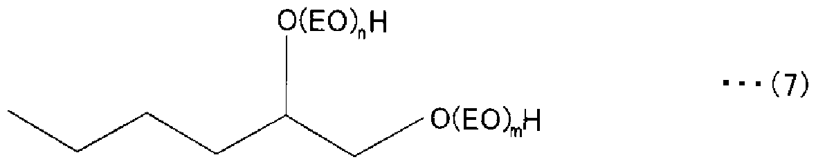


Claims


Priority Applications (5)
| Application Number | Priority Date | Filing Date | Title |
|---|---|---|---|
| KR1020067006247A KR101162380B1 (ko) | 2005-04-19 | 2005-04-19 | 기록액, 액체 카트리지, 액체 토출 장치 및 액체 토출 방법 |
| EP05733992A EP1876208A4 (en) | 2005-04-19 | 2005-04-19 | RECORDING LIQUID, LIQUID CARTRIDGE, LIQUID EXPRESSION DEVICE AND LIQUID DISPENSING METHOD |
| JP2007514379A JPWO2006114867A1 (ja) | 2005-04-19 | 2005-04-19 | 記録液、液体カートリッジ、液体吐出装置及び液体吐出方法 |
| PCT/JP2005/007482 WO2006114867A1 (ja) | 2005-04-19 | 2005-04-19 | 記録液、液体カートリッジ、液体吐出装置及び液体吐出方法 |
| CNA2005800010229A CN1946816A (zh) | 2005-04-19 | 2005-04-19 | 记录液体、液体盒、液体喷射装置和液体喷射方法 |
Applications Claiming Priority (1)
| Application Number | Priority Date | Filing Date | Title |
|---|---|---|---|
| PCT/JP2005/007482 WO2006114867A1 (ja) | 2005-04-19 | 2005-04-19 | 記録液、液体カートリッジ、液体吐出装置及び液体吐出方法 |
Publications (1)
| Publication Number | Publication Date |
|---|---|
| WO2006114867A1 true WO2006114867A1 (ja) | 2006-11-02 |
Family
ID=37214505
Family Applications (1)
| Application Number | Title | Priority Date | Filing Date |
|---|---|---|---|
| PCT/JP2005/007482 Ceased WO2006114867A1 (ja) | 2005-04-19 | 2005-04-19 | 記録液、液体カートリッジ、液体吐出装置及び液体吐出方法 |
Country Status (5)
| Country | Link |
|---|---|
| EP (1) | EP1876208A4 (ja) |
| JP (1) | JPWO2006114867A1 (ja) |
| KR (1) | KR101162380B1 (ja) |
| CN (1) | CN1946816A (ja) |
| WO (1) | WO2006114867A1 (ja) |
Families Citing this family (3)
| Publication number | Priority date | Publication date | Assignee | Title |
|---|---|---|---|---|
| JP5330763B2 (ja) * | 2007-09-25 | 2013-10-30 | 富士フイルム株式会社 | 画像形成方法及び画像形成装置 |
| CN106103609B (zh) * | 2014-03-28 | 2020-11-03 | 马姆杰特科技有限公司 | 用于改善印刷头寿命的油墨配制品 |
| JP7505261B2 (ja) * | 2020-05-21 | 2024-06-25 | セイコーエプソン株式会社 | 圧電素子、液体吐出ヘッドおよび液体吐出装置 |
Citations (4)
| Publication number | Priority date | Publication date | Assignee | Title |
|---|---|---|---|---|
| JPH0770491A (ja) * | 1993-09-03 | 1995-03-14 | Ricoh Co Ltd | インクジェット用記録液及びそれを用いた記録方法 |
| JPH1046075A (ja) * | 1995-11-30 | 1998-02-17 | Dainippon Ink & Chem Inc | インクジェット記録用水性インク |
| JP2003192966A (ja) * | 2001-12-26 | 2003-07-09 | Sakata Corp | 水性インクジェット用インク組成物 |
| JP2005008853A (ja) * | 2003-05-29 | 2005-01-13 | Sony Corp | 記録液、液体カートリッジ、液体吐出装置及び液体吐出方法 |
Family Cites Families (8)
| Publication number | Priority date | Publication date | Assignee | Title |
|---|---|---|---|---|
| DE19749082A1 (de) * | 1997-11-06 | 1999-05-12 | Bayer Ag | Nanoskalige anorganische Pigmente enthaltende Ink-Jet-Tinten |
| GB2357514A (en) * | 1999-12-23 | 2001-06-27 | Sericol Ltd | An ink for decoration of paper substrates for poster displays |
| JP5268219B2 (ja) * | 2000-09-28 | 2013-08-21 | ヒューレット−パッカード デベロップメント カンパニー エル.ピー. | 市販のオフセット媒体及びオフセットインクと併用される水性インクジェットインク |
| US6444017B1 (en) * | 2000-10-30 | 2002-09-03 | Hewlett-Packard Company | Aqueous ink jet inks for use with commercial offset media and offset ink |
| US6776830B2 (en) * | 2001-04-17 | 2004-08-17 | Seiko Epson Corporation | Aqueous ink composition for use in an ink-jet printer |
| US6881250B2 (en) * | 2003-01-15 | 2005-04-19 | Xerox Corporation | Tailored ink for piston driven electrostatic liquid drop modulator |
| JP4517591B2 (ja) * | 2003-06-05 | 2010-08-04 | 富士ゼロックス株式会社 | インクジェット用インクセット、及びインクジェット記録方法 |
| US20050137282A1 (en) * | 2003-12-19 | 2005-06-23 | Cagle Phillip C. | Liquid vehicle systems for improving latex ink-jet ink frequency response |
-
2005
- 2005-04-19 KR KR1020067006247A patent/KR101162380B1/ko not_active Expired - Fee Related
- 2005-04-19 EP EP05733992A patent/EP1876208A4/en not_active Withdrawn
- 2005-04-19 WO PCT/JP2005/007482 patent/WO2006114867A1/ja not_active Ceased
- 2005-04-19 JP JP2007514379A patent/JPWO2006114867A1/ja active Pending
- 2005-04-19 CN CNA2005800010229A patent/CN1946816A/zh active Pending
Patent Citations (4)
| Publication number | Priority date | Publication date | Assignee | Title |
|---|---|---|---|---|
| JPH0770491A (ja) * | 1993-09-03 | 1995-03-14 | Ricoh Co Ltd | インクジェット用記録液及びそれを用いた記録方法 |
| JPH1046075A (ja) * | 1995-11-30 | 1998-02-17 | Dainippon Ink & Chem Inc | インクジェット記録用水性インク |
| JP2003192966A (ja) * | 2001-12-26 | 2003-07-09 | Sakata Corp | 水性インクジェット用インク組成物 |
| JP2005008853A (ja) * | 2003-05-29 | 2005-01-13 | Sony Corp | 記録液、液体カートリッジ、液体吐出装置及び液体吐出方法 |
Non-Patent Citations (1)
| Title |
|---|
| See also references of EP1876208A4 * |
Also Published As
| Publication number | Publication date |
|---|---|
| KR20080000499A (ko) | 2008-01-02 |
| EP1876208A1 (en) | 2008-01-09 |
| EP1876208A4 (en) | 2008-05-28 |
| JPWO2006114867A1 (ja) | 2008-12-11 |
| CN1946816A (zh) | 2007-04-11 |
| KR101162380B1 (ko) | 2012-07-04 |
Similar Documents
| Publication | Publication Date | Title |
|---|---|---|
| US8075125B2 (en) | Liquid spraying cartridge containing a recording liquid having a pH of over 4 and under 6 | |
| JP2006117883A (ja) | 記録液、液体カートリッジ、液体吐出装置及び液体吐出方法 | |
| US20070206060A1 (en) | Recording liquid, liquid cartridge, liquid ejection cartridge, liquid ejection apparatus, and liquid ejection method | |
| JP2006182800A (ja) | 記録液、液体カートリッジ、液体吐出装置及び液体吐出方法 | |
| US7470017B2 (en) | Recording liquid, liquid cartridge emitting device and liquid emitting method | |
| JPWO2005054382A1 (ja) | 記録液、液体カートリッジ、液体吐出装置及び液体吐出方法 | |
| WO2006114867A1 (ja) | 記録液、液体カートリッジ、液体吐出装置及び液体吐出方法 | |
| JP4760359B2 (ja) | 記録液、液体カートリッジ、液体吐出装置及び液体吐出方法 | |
| JP4075758B2 (ja) | 記録液、液体カートリッジ、液体吐出装置及び液体吐出方法 | |
| WO2005037938A1 (ja) | 記録液、液体カートリッジ、液体吐出装置及び液体吐出方法 | |
| JP2005008853A (ja) | 記録液、液体カートリッジ、液体吐出装置及び液体吐出方法 | |
| JP2006117772A (ja) | 記録液、液体カートリッジ、液体吐出装置及び液体吐出方法 | |
| JP2005225002A (ja) | 液体カートリッジ、液体吐出カートリッジ、液体吐出装置及び液体吐出方法 | |
| JP2006188633A (ja) | 記録液、液体カートリッジ、液体吐出装置及び液体吐出方法 | |
| JP2008063540A (ja) | 記録液製造装置及び記録液の製造方法 | |
| JP2007161959A (ja) | 記録液、液体カートリッジ、液体吐出装置及び液体吐出方法 | |
| JP2006117802A (ja) | インク、インクカートリッジ、及びインクジェット記録方法 | |
| JP2006117773A (ja) | 記録液、液体カートリッジ、液体吐出装置及び液体吐出方法 | |
| JP2007002069A (ja) | 記録液、記録液カートリッジ及び記録方法 |
Legal Events
| Date | Code | Title | Description |
|---|---|---|---|
| WWE | Wipo information: entry into national phase |
Ref document number: 200580001022.9 Country of ref document: CN |
|
| WWE | Wipo information: entry into national phase |
Ref document number: 2007514379 Country of ref document: JP |
|
| WWE | Wipo information: entry into national phase |
Ref document number: 2005733992 Country of ref document: EP |
|
| WWE | Wipo information: entry into national phase |
Ref document number: 1020067006247 Country of ref document: KR |
|
| 121 | Ep: the epo has been informed by wipo that ep was designated in this application | ||
| NENP | Non-entry into the national phase |
Ref country code: DE |
|
| NENP | Non-entry into the national phase |
Ref country code: RU |
|
| WWW | Wipo information: withdrawn in national office |
Ref document number: RU |
|
| WWP | Wipo information: published in national office |
Ref document number: 2005733992 Country of ref document: EP |