WO2006138135A2 - Efficient filter weight computation for a mimo system - Google Patents
Efficient filter weight computation for a mimo system Download PDFInfo
- Publication number
- WO2006138135A2 WO2006138135A2 PCT/US2006/022228 US2006022228W WO2006138135A2 WO 2006138135 A2 WO2006138135 A2 WO 2006138135A2 US 2006022228 W US2006022228 W US 2006022228W WO 2006138135 A2 WO2006138135 A2 WO 2006138135A2
- Authority
- WO
- WIPO (PCT)
- Prior art keywords
- matrix
- channel response
- deriving
- spatial filter
- processor
- Prior art date
- Legal status (The legal status is an assumption and is not a legal conclusion. Google has not performed a legal analysis and makes no representation as to the accuracy of the status listed.)
- Ceased
Links
Classifications
-
- H—ELECTRICITY
- H04—ELECTRIC COMMUNICATION TECHNIQUE
- H04B—TRANSMISSION
- H04B7/00—Radio transmission systems, i.e. using radiation field
- H04B7/02—Diversity systems; Multi-antenna system, i.e. transmission or reception using multiple antennas
- H04B7/04—Diversity systems; Multi-antenna system, i.e. transmission or reception using multiple antennas using two or more spaced independent antennas
- H04B7/08—Diversity systems; Multi-antenna system, i.e. transmission or reception using multiple antennas using two or more spaced independent antennas at the receiving station
- H04B7/0837—Diversity systems; Multi-antenna system, i.e. transmission or reception using multiple antennas using two or more spaced independent antennas at the receiving station using pre-detection combining
- H04B7/0842—Weighted combining
- H04B7/0848—Joint weighting
- H04B7/0854—Joint weighting using error minimizing algorithms, e.g. minimum mean squared error [MMSE], "cross-correlation" or matrix inversion
-
- H—ELECTRICITY
- H04—ELECTRIC COMMUNICATION TECHNIQUE
- H04B—TRANSMISSION
- H04B7/00—Radio transmission systems, i.e. using radiation field
- H04B7/02—Diversity systems; Multi-antenna system, i.e. transmission or reception using multiple antennas
- H04B7/04—Diversity systems; Multi-antenna system, i.e. transmission or reception using multiple antennas using two or more spaced independent antennas
- H04B7/0413—MIMO systems
-
- H—ELECTRICITY
- H04—ELECTRIC COMMUNICATION TECHNIQUE
- H04L—TRANSMISSION OF DIGITAL INFORMATION, e.g. TELEGRAPHIC COMMUNICATION
- H04L1/00—Arrangements for detecting or preventing errors in the information received
- H04L1/02—Arrangements for detecting or preventing errors in the information received by diversity reception
-
- H—ELECTRICITY
- H04—ELECTRIC COMMUNICATION TECHNIQUE
- H04L—TRANSMISSION OF DIGITAL INFORMATION, e.g. TELEGRAPHIC COMMUNICATION
- H04L25/00—Baseband systems
- H04L25/02—Details ; arrangements for supplying electrical power along data transmission lines
- H04L25/03—Shaping networks in transmitter or receiver, e.g. adaptive shaping networks
- H04L25/03006—Arrangements for removing intersymbol interference
- H04L2025/0335—Arrangements for removing intersymbol interference characterised by the type of transmission
- H04L2025/03426—Arrangements for removing intersymbol interference characterised by the type of transmission transmission using multiple-input and multiple-output channels
-
- H—ELECTRICITY
- H04—ELECTRIC COMMUNICATION TECHNIQUE
- H04L—TRANSMISSION OF DIGITAL INFORMATION, e.g. TELEGRAPHIC COMMUNICATION
- H04L25/00—Baseband systems
- H04L25/02—Details ; arrangements for supplying electrical power along data transmission lines
- H04L25/03—Shaping networks in transmitter or receiver, e.g. adaptive shaping networks
- H04L25/03006—Arrangements for removing intersymbol interference
- H04L2025/03592—Adaptation methods
- H04L2025/03598—Algorithms
- H04L2025/03605—Block algorithms
-
- H—ELECTRICITY
- H04—ELECTRIC COMMUNICATION TECHNIQUE
- H04L—TRANSMISSION OF DIGITAL INFORMATION, e.g. TELEGRAPHIC COMMUNICATION
- H04L25/00—Baseband systems
- H04L25/02—Details ; arrangements for supplying electrical power along data transmission lines
- H04L25/03—Shaping networks in transmitter or receiver, e.g. adaptive shaping networks
- H04L25/03006—Arrangements for removing intersymbol interference
- H04L2025/03592—Adaptation methods
- H04L2025/03598—Algorithms
- H04L2025/03611—Iterative algorithms
-
- H—ELECTRICITY
- H04—ELECTRIC COMMUNICATION TECHNIQUE
- H04L—TRANSMISSION OF DIGITAL INFORMATION, e.g. TELEGRAPHIC COMMUNICATION
- H04L25/00—Baseband systems
- H04L25/02—Details ; arrangements for supplying electrical power along data transmission lines
- H04L25/0202—Channel estimation
- H04L25/024—Channel estimation channel estimation algorithms
- H04L25/0242—Channel estimation channel estimation algorithms using matrix methods
- H04L25/0246—Channel estimation channel estimation algorithms using matrix methods with factorisation
-
- H—ELECTRICITY
- H04—ELECTRIC COMMUNICATION TECHNIQUE
- H04L—TRANSMISSION OF DIGITAL INFORMATION, e.g. TELEGRAPHIC COMMUNICATION
- H04L25/00—Baseband systems
- H04L25/02—Details ; arrangements for supplying electrical power along data transmission lines
- H04L25/0202—Channel estimation
- H04L25/024—Channel estimation channel estimation algorithms
- H04L25/0242—Channel estimation channel estimation algorithms using matrix methods
- H04L25/0248—Eigen-space methods
Definitions
- the present disclosure relates generally to communication, and more specifically to techniques for computing filter weights in a communication system.
- a multiple-input multiple-output (MIMO) communication system employs multiple (T) transmit antennas at a transmitting station and multiple (R) receive antennas at a receiving station for data transmission.
- a MBvIO channel formed by the T transmit antennas and the R receive antennas may be decomposed into S spatial channels, where S ⁇ min ⁇ T, R ⁇ .
- the S spatial channels may be used to transmit data in a manner to achieve higher overall throughput and/or greater reliability.
- the transmitting station may simultaneously transmit T data streams from the T transmit antennas. These data streams are distorted by the MIMO channel response and further degraded by noise and interference.
- the receiving station receives the transmitted data streams via the R receive antennas.
- the received signal from each receive antenna contains scaled versions of the T data streams sent by the transmitting station.
- the transmitted data streams are thus dispersed among the R received signals from the R receive antennas.
- the receiving station would then perform receiver spatial processing on the R received signals with a spatial filter matrix in order to recover the transmitted data streams.
- a Hermitian matrix P is iteratively derived based on a channel response matrix H , and a matrix inversion is indirectly calculated by deriving the Hermitian matrix iteratively.
- the Hermitian matrix may be initialized to an identity matrix. One iteration is then performed for each row of the channel response matrix, and an efficient sequence of calculations is performed for each iteration.
- an intermediate row vector a is derived based on a channel response row vector h, , which is the z-th row of the channel response matrix.
- a scalar r t is derived based on the intermediate row vector and the channel response row vector.
- An intermediate matrix C,- is also derived based on the intermediate row vector.
- the Hermitian matrix is then updated based on the scalar and the intermediate matrix.
- the spatial filter matrix is derived based on the Hermitian matrix and the channel response matrix.
- multiple rotations are performed to iteratively obtain a first matrix P and a second matrix B for a pseudo-inverse matrix of the channel response matrix.
- a matrix Y containing the first and second matrices from the prior iteration is formed. Multiple Givens rotations are then performed on matrix Y to zero out elements in the first row of the matrix to obtain updated first and second matrices for the next iteration. After all of the iterations are completed, the spatial filter matrix is derived based on the first and second matrices.
- a matrix X is formed based on the channel response matrix and decomposed (e.g., using eigenvalue decomposition) to obtain a unitary matrix V and a diagonal matrix ⁇ .
- the decomposition may be achieved by iteratively performing Jacobi rotations on matrix X .
- the spatial filter matrix is then derived based on the unitary matrix, the diagonal matrix, and the channel response matrix.
- FIGS. 1, 2 and 3 show processes for computing an MMSE spatial filter matrix based on the first, second, and third embodiments, respectively.
- FIG. 4 shows a block diagram of an access point and a user terminal.
- the filter weight computation techniques described herein may be used for a single-carrier MEVIO system and a multi-carrier MEVIO system.
- Multiple carriers may be obtained with orthogonal frequency division multiplexing (OFDM), interleaved frequency division multiple access (IFDMA), localized frequency division multiple access (LFDMA), or some other modulation technique.
- OFDM, IFDMA, and LFDMA effectively partition the overall system bandwidth into multiple (K) orthogonal frequency subbands, which are also called tones, subcarriers, bins, and frequency channels. Each subband is associated with a respective subcarrier that may be modulated with data.
- OFDM transmits modulation symbols in the frequency domain on all or a subset of the K subbands.
- EFDMA transmits modulation symbols in the time domain on subbands that are uniformly spaced across the K subbands.
- LFDMA transmits modulation symbols in the time domain and typically on adjacent subbands. For clarity, much of the following description is for a single-carrier MEVIO system with a single subband.
- a MDVlO channel formed by multiple (T) transmit antennas at a transmitting station and multiple (R) receive antennas at a receiving station may be characterized by an R x T channel response matrix H , which may be given as:
- the transmitting station may transmit T modulation symbols simultaneously from the T transmit antennas in each symbol period.
- the transmitting station may or may not perform spatial processing on the modulation symbols prior to transmission.
- each modulation symbol is sent from one transmit antenna without any spatial processing.
- the receiving station obtains R received symbols from the R receive antennas in each symbol period.
- the received symbols may be expressed as:
- s is a TxI vector with T modulation symbols sent by the transmitting station
- r is an R xI vector with R received symbols obtained by the receiving station from the R receive antennas
- n is an R x 1 vector of noise.
- the noise may be assumed to be additive white Gaussian noise (AWGN) with a zero mean vector and a covariance matrix of ⁇ I , where is the variance of the noise and I is the identity matrix.
- AWGN additive white Gaussian noise
- the receiving station may use various receiver spatial processing techniques to recover the modulation symbols sent by the transmitting station.
- M is a T xR MMSE spatial filter matrix
- P is a TxT Hermitian covariance matrix for the estimation error s-s ;
- I is a T x 1 vector that is an estimate of s ; and
- ff denotes a conjugate transpose.
- the MMS ⁇ spatial filter matrix M has a matrix inverse calculation. Direct calculation of the matrix inversion is computationally intensive.
- the MMS ⁇ spatial filter matrix may be more efficiently derived based on the embodiments described below, which indirectly calculate the matrix inversion with an iterative process instead of directly calculating the matrix inversion.
- the Hermitian matrix P is computed based on the Riccati equation. Hermitian matrix P may be expressed as:
- a TxT Hermitian matrix P,- may be defined as:
- Equation (5) The matrix inversion lemma may be applied to equation (5) to obtain the following:
- Equation (6) is referred to as the Riccati equation.
- Equation (6) may be factored to obtain the following:
- Equations (6) and (7) are different forms of a solution to equation (5).
- the same variables P, and r t are used for both equations (6) and (7) even though these variables have different values in the two equations.
- P 0 is an identity matrix
- a is a IxT intermediate row vector of complex-valued elements
- C is a T x T intermediate Hermitian matrix
- Equation set (8) the sequence of operations is structured for efficient computation by hardware.
- Scalar ⁇ is computed before matrix C 1 .
- the division by ⁇ in equation (7) is achieved with an inversion and a multiply.
- the inversion of ⁇ may be performed in parallel with the computation of C, .
- the inversion of r t may be achieved with a shifter to normalize ⁇ and a look-up table to produce an inverted ⁇ value.
- the normalization of ⁇ may be compensated for in the multiplication with C, .
- FIG. 1 shows a process 100 for computing the MMSE spatial filter matrix M based on the first embodiment.
- each iteration of the Riccati equation is performed by block 120.
- the intermediate row vector a is computed based on the channel response row vector h, and the Hermitian matrix P 1-1 from the prior iteration, as shown in equation (8a) (block 122).
- the scalar ⁇ is computed based on the noise variance , the intermediate row vector a, , and the channel response row vector h, , as shown in equation (8b) (block 124).
- Scalar ⁇ is then inverted (block 126).
- Intermediate matrix C is computed based on the intermediate row vector a, , as shown in equation (8c) (block 128).
- Matrix P 1 is then updated based on the inverted scalar ⁇ and the intermediate matrix C 1 , as shown in equation (8d) (block 130).
- the Hermitian matrix P is determined by deriving the square root of P , which is P 1/2 , based on an iterative procedure.
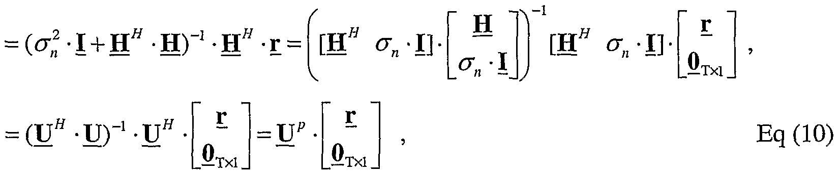
- the receiver spatial processing in equation (3) may be expressed as:
- QR decomposition may be performed on the augmented channel matrix, as follows:
- Q is a (R +T) x T matrix with orthonormal columns; R is a T x T matrix that is non-singular; B is an R xT matrix containing the first R rows of Q ; and Q 2 is a TxT matrix containing the last T rows of Q .
- the QR decomposition in equation (11) decomposes the augmented channel matrix into an orthonormal matrix Q and a non-singular matrix R .
- a non-singular matrix is a matrix that an inverse can be computed for.
- the Hermitian matrix P may then be expressed as:
- R is the Cholesky factorization or matrix square root of P . Hence, P is equal to
- R 1 and is called the square-root of P .
- Sub-matrix H ⁇ . which is also the MMSE spatial filter matrix, may then be expressed as:
- Equation (10) may then be expressed as:
- Matrices P 1/2 and B may be computed iteratively as follows:
- Y 1 . is a (T + R + l)x(T + l) matrix containing elements derived based on P , M 1/2 ,
- B M and h,- ; ⁇ ; is a (T + 1) x (T + 1) unitary transformation matrix;
- Z is a (T + R + 1) x (T + 1) transformed matrix containing elements for P, 1/2 ,
- e is an R xI vector with one (1.0) as the i-th element and zeros elsewhere; and k, is a TxI vector and I 1 is an R xI vector, both of which are non-essential.
- the first column of the transformed matrix Z 1 contains rl 12 , k, , and I 1 .
- the last T columns of Z contain updated P, 1/2 and B, .
- the first column of Z 1 does not need to be calculated since only P 1 and B, are used in the next iteration.
- P, 1/2 is an upper triangular matrix.
- P R /2 is provided as P m
- B R is provided as B .
- the MMSE spatial filter matrix M may then be computed as based on P 1/2 and B , as shown in equation
- the transformation in equation (17) may be performed by successively zeroing out one element in the first row of Y 1 at a time with a 2 x 2 Givens rotation.
- T inner iterations of the Givens rotation may be performed to zero out the last T elements in the first row of Y 1 .
- Givens rotation may be expressed as:
- the Givens rotation may be performed in- place on two columns of Y 1 for each inner iteration, so that intermediate matrices Y 1 ; , Y -Ij > Y ⁇ 1J an( i Y, ,j+ i a ⁇ e n °t needed and are described above for clarity.
- the Givens rotation matrix G tJ is determined based on the first element (which is always a real value) and the (j ' + l) -th element in the first row of Y 1 ⁇ .
- the first element may be denoted as a
- the ( j + 1) -th element may be denoted as b • e j ⁇ .
- the Givens rotation matrix G 1 may then be derived as follows:
- FIG. 2 shows a process 200 for computing the MMSE spatial filter matrix
- R outer iterations of the unitary transformation in equation (17) are then performed (block 220).
- matrix Y 1 is initially formed with the channel response row vector h, and matrices P 1- .', 2 and B 1-1 , as shown in equation (17) (block 222).
- Matrix Y is then referred to as matrix Y I>; for the inner iterations (block 224).
- T inner iterations of the Givens rotation are then performed on matrix Y, 7 (block 230).
- the Givens rotation matrix G (J is derived based on the first and (j + ⁇ ) -th elements in the first row of Y_ tJ , as shown in equation (19) (block 232).
- the Givens rotation matrix G (J is then applied to the first and (j + 1) -th columns of Y 1 . _ ; to obtain Y,- ,J+ i , as shown in equation (18) (block 234).
- a determination is then made whether all T inner iterations have been performed (block 236). If the answer is 'No', then index j is incremented (block 238), and the process returns to block 232 to perform another inner iteration.
- V is a TxT unitary matrix of eigenvectors
- ⁇ is a TxT diagonal matrix with real eigenvalues along the diagonal.
- Eigenvalue decomposition of a 2x2 Hermitian matrix X 2x2 may be achieved using various techniques.
- eigenvalue decomposition of X 2x2 is achieved by performing a complex Jacobi rotation on X 2x2 to obtain a 2x2 matrix V 2x2 of eigenvectors of X 2x2 .
- the elements of X 2x2 and V 2x2 may be given as:
- V 2x2 may be computed directly from the elements of X 2x2 , as follows:
- Eigenvalue decomposition of a T xT Hermitian matrix X that is larger than 2x2 may be performed with an iterative process. This iterative process uses the Jacobi rotation repeatedly to zero out off-diagonal elements in X .
- a single iteration of the Jacobi rotation to update matrices D,- and V 1 - may be performed as follows. First, a 2x2 Hermitian matrix D ⁇ is formed based on the current matrix D,- , as follows:
- D pq is a 2x2 submatrix of D 1 .
- the four elements of O pq are four elements al locations (p,p) , (p,q) , (q,p) and (q, q) in D,. .
- Indices p and q may be selected as described below.
- Eigenvalue decomposition of J) pq is then performed as shown in equation set (22) to obtain a 2x2 unitary matrix V pg of eigenvectors of O pq .
- X 2x2 in equation (21) is replaced with D ffl , and
- V 2x2 from equation (22j) or (22k) is provided as ⁇ _ pq .
- T_ pq is an identity matrix with four elements at locations (p, p) , (p, q) , (q, p) and (q, q) replaced with elements V 1 1 , V 1 2 , V 2 1 and V 2 2 , respectively, in Y_ pq .
- Matrix D is then updated as follows:
- n M l " ⁇ -Url p ⁇ ⁇ Eq (24)
- Equation (24) zeros out two off-diagonal elements at locations (p,q) and (q,p) in D,- .
- the computation may alter the values of other off-diagonal elements in D 1 ..
- Matrix V 1 - is also updated as follows:
- V 4+1 V, - T M . Eq (25)
- V,- may be viewed as a cumulative transformation matrix that contains all of the Jacobi rotation matrices ⁇ _ pq used on D,- .
- Each iteration of the Jacobi rotation zeros out two off-diagonal elements of D 1 .. Multiple iterations of the Jacobi rotation may be performed for different values of indices p and q to zero out all of the off-diagonal elements of D,- .
- a single sweep across all possible values of indices p and q may be performed as follows. Index p is stepped from 1 through T - 1 in increments of one. For each value of p, index q is stepped from p + 1 through T in increments of one. The Jacobi rotation is performed for each different combination of values forp and q. Multiple sweeps may be performed until D,. and V 1 - are sufficiently accurate estimates of ⁇ and V , respectively.
- Equation (20) may be rewritten as follows:
- AT 1 is a diagonal matrix whose elements are the inverse of the corresponding elements in ⁇ .
- V . ⁇ may be inverted to obtain ⁇ "1 .
- the MMSE spatial filter matrix may then be computed as follows:
- FIG. 3 shows a process 300 for computing the MMSE spatial filter matrix M based on the third embodiment.
- Hermitian matrix P "1 is initially derived based on the channel response matrix H , as shown in equation (20) (block 312).
- Eigenvalue decomposition of P "1 is then performed to obtain unitary matrix V and diagonal matrix ⁇ , as also shown in equation (20) (block 314).
- the eigenvalue decomposition may be iteratively performed with a number of Jacobi rotations, as described above.
- the MMSE spatial filter matrix M is then derived based on the unitary matrix V , the diagonal matrix ⁇ , and the channel response matrix H , as shown in equation (27) (block 316).
- the MMSE spatial filter matrix M derived based on each of the embodiments described above is a biased MMSE solution.
- the biased spatial filter matrix M may be scaled by a diagonal matrix D mni ⁇ e to obtain an unbiased MMSE spatial filter matrix M mmse .
- the computation described above may also be used to derive spatial filter matrices for a zero-forcing (ZF) technique (which is also called a channel correlation matrix inversion (CCMI) technique), a maximal ratio combining (MRC) technique, and so on.
- ZF zero-forcing
- CCMI channel correlation matrix inversion
- MRC maximal ratio combining
- the receiving station may perform zero-forcing and MRC receiver spatial processing, as follows:
- M- ⁇ is a T x R zero-forcing spatial filter matrix
- M mrc is a TxR MRC spatial filter matrix
- P ⁇ (H" - H) "1 is a TxT Hermitian matrix
- [diag (P z/ )] is a TxT diagonal matrix containing the diagonal elements of P z/ .
- P tf may be computed using the embodiments described above for the MMSE spatial filter matrix.
- x is a TxI vector with T transmit symbols to be sent from the T transmit antennas
- W is a TxS transmit matrix.
- Transmit matrix W may be (1) a matrix of right singular vectors obtained by performing singular value decomposition of H , (2) a matrix of eigenvectors obtained by performing eigenvalue decomposition of ⁇ .” • H , or (3) a steering matrix selected to spatially spread the modulation symbols across the S spatial channels of the MDVIO channel.
- the computation described above may be performed based on H e# instead of H .
- a channel response matrix H(fc) may be obtained for each subband k of interest.
- a spatial filter matrix M(Jc) may then be derived for each subband k based on the channel response matrix H(Z:) for that subband.
- the computation described above for the spatial filter matrix may be performed using various types of processors such as a floating-point processor, a fixed- point processor, a Coordinate Rotational Digital Computer (CORDIC) processor, a look-up table, and so on, or a combination thereof.
- a CORDIC processor implements an iterative algorithm that allows for fast hardware calculation of trigonometric functions such as sine, cosine, magnitude, and phase using simple shift and add/subtract hardware.
- a CORDIC processor may iteratively compute each of variables r, C 1 and S 1 in equation set (22), with more iterations producing higher accuracy for the variable.
- a transmit (TX) data processor 414 receives traffic data from a data source 412 and other data from a controller/processor 430. TX data processor 414 formats, encodes, interleaves, and modulates the data and generates data symbols, which are modulation symbols for data.
- a TX spatial processor 420 multiplexes the data symbols with pilot symbols, performs spatial processing with transmit matrix W if applicable, and provides N ap streams of transmit symbols.
- Each transmitter unit (TMTR) 422 processes a respective transmit symbol stream and generates a downlink modulated signal.
- N ap downlink modulated signals from transmitter units 422a through 422ap are transmitted from antennas 424a through 424ap, respectively.
- N ut antennas 452a through 452ut receive the transmitted downlink modulated signals, and each antenna provides a received signal to a respective receiver unit (RCVR) 454.
- Each receiver unit 454 performs processing complementary to the processing performed by transmitter units 422 and provides received pilot symbols and received data symbols.
- a channel estimator/processor 478 processes the received pilot symbols and provides an estimate of the downlink channel response H dn .
- a processor 480 derives a downlink spatial filter matrix M dn based on H dn and using any of the embodiments described above.
- a receive (RX) spatial processor 460 performs receiver spatial processing (or spatial matched filtering) on the received data symbols from all N ut receiver units 454a through 454ut with the downlink spatial filter matrix M dn and provides detected data symbols, which are estimates of the data symbols transmitted by access point 410.
- An RX data processor 470 processes (e.g., symbol demaps, deinterleaves, and decodes) the detected data symbols and provides decoded data to a data sink 472 and/or controller 480.
- the processing for the uplink may be the same or different from the processing for the downlink.
- Data from a data source 486 and signaling from controller 480 are processed (e.g., encoded, interleaved, and modulated) by a TX data processor 488, multiplexed with pilot symbols, and possibly spatially processed by TX spatial processor 490.
- the transmit symbols from TX spatial processor 490 are further processed by transmitter units 454a through 454ut to generate N ut uplink modulated signals, which are transmitted via antennas 452a through 452ut.
- the uplink modulated signals are received by antennas 424a through 424ap and processed by receiver units 422a through 422ap to generate received pilot symbols and received data symbols for the uplink transmission.
- a channel estimator/processor 428 processes the received pilot symbols and provides an estimate of the uplink channel response H up .
- Processor 430 derives an uplink spatial filter matrix M up based on H up and using any of the embodiments described above.
- RX spatial processor 440 performs receiver spatial processing on the received data symbols with the uplink spatial filter matrix M up and provides detected data symbols.
- An RX data processor 442 further processes the detected data symbols and provides decoded data to a data sink 444 and/or controller 430.
- Controllers 430 and 480 control the operation at access point 410 and user terminal 450, respectively.
- Memory units 432 and 482 store data and program codes used by controllers 430 and 480, respectively.
- the blocks in FIGS. 1 through 4 represent functional blocks that may be embodied in hardware (one or more devices), firmware (one or more devices), software (one or more modules), or combinations thereof.
- the filter weight computation techniques described herein may be implemented in hardware, firmware, software, or a combination thereof.
- the processing units used to compute the filter weights may be implemented within one or more application specific integrated circuits (ASICs), digital signal processors (DSPs), digital signal processing devices (DSPDs), programmable logic devices (PLDs), field programmable gate arrays (FPGAs), processors, controllers, micro-controllers, microprocessors, electronic devices, other electronic units designed to perform the functions described herein, or a combination thereof.
- the various processors at access point 410 in FIG. 4 may also be implemented with one or more hardware processors.
- the various processors at user terminal 450 may be implemented with one or more hardware processors.
- the filter weight computation techniques may be implemented with modules (e.g., procedures, functions, and so on) that perform the functions described herein.
- the software codes may be stored in a memory unit (e.g., memory unit 432 or 482 in FIG. 4) and executed by a processor (e.g., processor 430 or 480).
- the memory unit may be implemented within the processor or external to the processor.
Landscapes
- Engineering & Computer Science (AREA)
- Computer Networks & Wireless Communication (AREA)
- Signal Processing (AREA)
- Physics & Mathematics (AREA)
- Mathematical Physics (AREA)
- Power Engineering (AREA)
- Radio Transmission System (AREA)
- Complex Calculations (AREA)
- Filters That Use Time-Delay Elements (AREA)
- Image Processing (AREA)
- Mobile Radio Communication Systems (AREA)
Abstract
Description


Claims


Priority Applications (9)
| Application Number | Priority Date | Filing Date | Title |
|---|---|---|---|
| EP06772504A EP1894329A4 (en) | 2005-06-16 | 2006-06-07 | Efficient filter weight computation for a mimo system |
| KR1020117015072A KR101078633B1 (en) | 2005-06-16 | 2006-06-07 | Efficient filter weight computation for a mimo system |
| BRPI0612225-6A BRPI0612225A2 (en) | 2005-06-16 | 2006-06-07 | efficient filter weight computation for a multiple input and multiple output system (minimum) |
| KR1020107009561A KR101162127B1 (en) | 2005-06-16 | 2006-06-07 | Efficient filter weight computation for a mimo system |
| CN200680029759.6A CN101243629B (en) | 2005-06-16 | 2006-06-07 | High Efficiency Filter Weight Calculation for MIMO System |
| JP2008516943A JP4955670B2 (en) | 2005-06-16 | 2006-06-07 | Efficient filter weight calculation for MIMO systems |
| KR1020117015071A KR101078632B1 (en) | 2005-06-16 | 2006-06-07 | Efficient filter weight computation for a mimo system |
| CA002612342A CA2612342A1 (en) | 2005-06-16 | 2006-06-07 | Efficient filter weight computation for a mimo system |
| KR1020107009562A KR101162126B1 (en) | 2005-06-16 | 2006-06-07 | Efficient filter weight computation for a mimo system |
Applications Claiming Priority (4)
| Application Number | Priority Date | Filing Date | Title |
|---|---|---|---|
| US69175605P | 2005-06-16 | 2005-06-16 | |
| US60/691,756 | 2005-06-16 | ||
| US11/158,586 US20060285531A1 (en) | 2005-06-16 | 2005-06-21 | Efficient filter weight computation for a MIMO system |
| US11/158,586 | 2005-06-21 |
Publications (2)
| Publication Number | Publication Date |
|---|---|
| WO2006138135A2 true WO2006138135A2 (en) | 2006-12-28 |
| WO2006138135A3 WO2006138135A3 (en) | 2007-10-04 |
Family
ID=37570976
Family Applications (1)
| Application Number | Title | Priority Date | Filing Date |
|---|---|---|---|
| PCT/US2006/022228 Ceased WO2006138135A2 (en) | 2005-06-16 | 2006-06-07 | Efficient filter weight computation for a mimo system |
Country Status (10)
| Country | Link |
|---|---|
| US (1) | US20060285531A1 (en) |
| EP (3) | EP2204931A3 (en) |
| JP (3) | JP4955670B2 (en) |
| KR (5) | KR101162127B1 (en) |
| CN (1) | CN101243629B (en) |
| BR (1) | BRPI0612225A2 (en) |
| CA (1) | CA2612342A1 (en) |
| RU (2) | RU2404513C2 (en) |
| SG (1) | SG162800A1 (en) |
| WO (1) | WO2006138135A2 (en) |
Cited By (4)
| Publication number | Priority date | Publication date | Assignee | Title |
|---|---|---|---|---|
| WO2009116910A1 (en) * | 2008-03-19 | 2009-09-24 | Telefonaktiebolaget L M Ericsson (Publ) | Simplified impairments matrix calculation for sinr estimation |
| WO2010033261A1 (en) * | 2008-09-17 | 2010-03-25 | Qualcomm Incorporated | An mmse mimo decoder using qr decomposition |
| WO2010033524A1 (en) * | 2008-09-17 | 2010-03-25 | Qualcomm Incorporated | Methods and systems for hybrid mimo decoding |
| CN101909031B (en) * | 2009-06-05 | 2013-06-26 | 北京信威通信技术股份有限公司 | MMSE detection method for spread-spectrum OFDMA communication system |
Families Citing this family (46)
| Publication number | Priority date | Publication date | Assignee | Title |
|---|---|---|---|---|
| US7366326B2 (en) * | 2003-06-24 | 2008-04-29 | University Of Maryland, Baltimore County | Real-time implementation of field programmable gate arrays (FPGA) design in hyperspectral imaging |
| US8204149B2 (en) | 2003-12-17 | 2012-06-19 | Qualcomm Incorporated | Spatial spreading in a multi-antenna communication system |
| US7336746B2 (en) | 2004-12-09 | 2008-02-26 | Qualcomm Incorporated | Data transmission with spatial spreading in a MIMO communication system |
| US8169889B2 (en) | 2004-02-18 | 2012-05-01 | Qualcomm Incorporated | Transmit diversity and spatial spreading for an OFDM-based multi-antenna communication system |
| US8285226B2 (en) | 2004-05-07 | 2012-10-09 | Qualcomm Incorporated | Steering diversity for an OFDM-based multi-antenna communication system |
| US8923785B2 (en) | 2004-05-07 | 2014-12-30 | Qualcomm Incorporated | Continuous beamforming for a MIMO-OFDM system |
| US7978649B2 (en) | 2004-07-15 | 2011-07-12 | Qualcomm, Incorporated | Unified MIMO transmission and reception |
| US7711762B2 (en) * | 2004-11-15 | 2010-05-04 | Qualcomm Incorporated | Efficient computation for eigenvalue decomposition and singular value decomposition of matrices |
| US7895254B2 (en) * | 2004-11-15 | 2011-02-22 | Qualcomm Incorporated | Eigenvalue decomposition and singular value decomposition of matrices using Jacobi rotation |
| JP4429945B2 (en) * | 2005-03-23 | 2010-03-10 | 株式会社エヌ・ティ・ティ・ドコモ | MIMO multiplex communication apparatus and signal separation method |
| US7830988B2 (en) * | 2005-03-28 | 2010-11-09 | Nec Corporation | MIMO decoder and MIMO decoding method |
| US7602855B2 (en) * | 2005-04-01 | 2009-10-13 | Interdigital Technology Corporation | Method and apparatus for singular value decomposition of a channel matrix |
| US8737494B2 (en) * | 2006-01-09 | 2014-05-27 | Broadcom Corporation | Method and system for quantization for a general beamforming matrix in feedback information |
| WO2007012053A1 (en) * | 2005-07-20 | 2007-01-25 | Stmicroelectronics, S.R.L. | Apparatus and method for detecting communications from multiple sources |
| WO2008110854A2 (en) * | 2007-03-14 | 2008-09-18 | Stmicroelectronics S.R.L. | A method and apparatus for multiple antenna communications, computer program product therefor |
| US9025689B2 (en) | 2005-07-20 | 2015-05-05 | Stmicroelectronics S.R.L. | Method and apparatus for multiple antenna communications, and related systems and computer program |
| TWI274482B (en) * | 2005-10-18 | 2007-02-21 | Ind Tech Res Inst | MIMO-OFDM system and pre-coding and feedback method therein |
| US7818357B2 (en) * | 2005-11-23 | 2010-10-19 | Rambus Inc. | Systems and methods for implementing CORDIC rotations for projectors and related operators |
| US8543070B2 (en) | 2006-04-24 | 2013-09-24 | Qualcomm Incorporated | Reduced complexity beam-steered MIMO OFDM system |
| US8290089B2 (en) | 2006-05-22 | 2012-10-16 | Qualcomm Incorporated | Derivation and feedback of transmit steering matrix |
| JP2008067308A (en) * | 2006-09-11 | 2008-03-21 | Fuji Xerox Co Ltd | Color processing device, color processing method, and program |
| US7995457B2 (en) * | 2007-04-16 | 2011-08-09 | Broadcom Corporation | Method and system for SFBC/STBC transmission of orthogonally coded signals with angle feedback in a diversity transmission system |
| US8457265B2 (en) * | 2007-08-23 | 2013-06-04 | Qualcomm Incorporated | Method and apparatus for generating coefficients in a multi-input-multi-output (MIMO) system |
| KR101329012B1 (en) * | 2007-10-11 | 2013-11-12 | 삼성전자주식회사 | A multiple input multiple output receiver and method for detecting signal thereof |
| JP5122428B2 (en) * | 2008-02-04 | 2013-01-16 | 株式会社エヌ・ティ・ティ・ドコモ | Mobile communication system, receiving apparatus and method |
| US8385439B2 (en) * | 2008-05-27 | 2013-02-26 | Nec Laboratories America, Inc. | Polarization mode dispersion compensation in multilevel coded-modulation schemes using blast algorithm and iterative polarization cancellation |
| CN101621354B (en) * | 2008-07-06 | 2013-07-31 | 财团法人工业技术研究院 | Signal detection method and receiving device using the method |
| TWI381668B (en) * | 2008-07-07 | 2013-01-01 | Ind Tech Res Inst | Signal detecting method and receiver using the same |
| WO2010056069A2 (en) * | 2008-11-14 | 2010-05-20 | 엘지전자주식회사 | Method and apparatus for data transmission using a plurality of resources in a multiple antenna system |
| KR100983126B1 (en) * | 2008-12-22 | 2010-09-17 | 성균관대학교산학협력단 | OPM channel equalizer and method |
| US8488724B2 (en) | 2009-05-14 | 2013-07-16 | Silvus Technologies, Inc. | Wideband interference mitigation for devices with multiple receivers |
| US8724746B2 (en) * | 2011-03-17 | 2014-05-13 | Futurewei Technologies, Inc. | System and method for signaling and detecting in wireless communications systems |
| TW201322006A (en) * | 2011-11-18 | 2013-06-01 | Ind Tech Res Inst | Data processing method and device using the same |
| KR101319795B1 (en) | 2011-12-23 | 2013-10-17 | 삼성전기주식회사 | Operation method of access point and wireless communication system using access point |
| CN102882579B (en) * | 2012-09-24 | 2015-01-28 | 东南大学 | Parallel matrix inversion method for multi-antenna system |
| US9819516B2 (en) | 2013-03-28 | 2017-11-14 | Nokia Solutions And Networks Oy | Channel estimation in wireless communications |
| CN103532890B (en) * | 2013-10-29 | 2017-03-29 | 东南大学 | A kind of SVD decomposition methods to complex channel matrix |
| US20160036561A1 (en) * | 2014-07-29 | 2016-02-04 | MagnaCom Ltd. | Orthogonal Frequency Division Multiplexing Based Communications Over Nonlinear Channels |
| US9485126B2 (en) * | 2014-08-21 | 2016-11-01 | The Boeing Company | Signal combining system for constant envelope transmission of information |
| US9525470B1 (en) * | 2015-10-19 | 2016-12-20 | Xilinx, Inc. | Adaptive multiple-input multiple-output (MIMO) data detection and precoding |
| CN106919537A (en) * | 2017-03-07 | 2017-07-04 | 电子科技大学 | A kind of efficient implementation method of the Jacobi conversion based on FPGA |
| WO2019141352A1 (en) * | 2018-01-17 | 2019-07-25 | Huawei Technologies Co., Ltd. | Signal decoder and method for performing hermitian matrix inversion |
| CN108512581B (en) * | 2018-03-01 | 2021-03-09 | 东南大学 | Precoding recurrence method for large-scale MIMO (multiple input multiple output) increasing and decreasing antennas |
| CN109004965B (en) * | 2018-07-26 | 2021-04-02 | 大连理工大学 | Design method and device of hybrid beam forming filter based on millimeter wave MIMO system secure communication |
| CN112596701B (en) * | 2021-03-05 | 2021-06-01 | 之江实验室 | FPGA acceleration realization method based on unilateral Jacobian singular value decomposition |
| US12284058B2 (en) * | 2022-06-16 | 2025-04-22 | Samsung Electronics Co., Ltd. | Self-tuning fixed-point least-squares solver |
Family Cites Families (21)
| Publication number | Priority date | Publication date | Assignee | Title |
|---|---|---|---|---|
| WO1998009385A2 (en) * | 1996-08-29 | 1998-03-05 | Cisco Technology, Inc. | Spatio-temporal processing for communication |
| US6600796B1 (en) * | 1999-11-12 | 2003-07-29 | Lucent Technologies Inc. | Method and apparatus for receiving wireless transmissions using multiple-antenna arrays |
| WO2001041343A1 (en) * | 1999-12-02 | 2001-06-07 | Samsung Electronics Co., Ltd | Apparatus and method for transmitting and receiving data in a cdma communication system |
| US6987819B2 (en) * | 2000-12-29 | 2006-01-17 | Motorola, Inc. | Method and device for multiple input/multiple output transmit and receive weights for equal-rate data streams |
| JP3714910B2 (en) * | 2001-02-20 | 2005-11-09 | 株式会社エヌ・ティ・ティ・ドコモ | Turbo receiving method and receiver thereof |
| US20030012315A1 (en) * | 2001-07-06 | 2003-01-16 | John Fan | System and method for multistage error correction coding wirelessly transmitted information in a multiple antennae communication system |
| US20030125040A1 (en) * | 2001-11-06 | 2003-07-03 | Walton Jay R. | Multiple-access multiple-input multiple-output (MIMO) communication system |
| EP1337082B1 (en) * | 2002-02-14 | 2005-10-26 | Lucent Technologies Inc. | Receiver and method for multi-input multi-output iterative detection using feedback of soft estimates |
| US7076263B2 (en) * | 2002-02-19 | 2006-07-11 | Qualcomm, Incorporated | Power control for partial channel-state information (CSI) multiple-input, multiple-output (MIMO) systems |
| EP1769585A4 (en) * | 2002-03-01 | 2009-12-02 | Ipr Licensing Inc | System and method for joint maximal ratio combining using time-domain based signal processing |
| US6636568B2 (en) * | 2002-03-01 | 2003-10-21 | Qualcomm | Data transmission with non-uniform distribution of data rates for a multiple-input multiple-output (MIMO) system |
| US6801580B2 (en) * | 2002-04-09 | 2004-10-05 | Qualcomm, Incorporated | Ordered successive interference cancellation receiver processing for multipath channels |
| US6757321B2 (en) * | 2002-05-22 | 2004-06-29 | Interdigital Technology Corporation | Segment-wise channel equalization based data estimation |
| US7613248B2 (en) * | 2002-06-24 | 2009-11-03 | Qualcomm Incorporated | Signal processing with channel eigenmode decomposition and channel inversion for MIMO systems |
| US7254192B2 (en) * | 2002-07-12 | 2007-08-07 | Texas Instruments Incorporated | Iterative detection in MIMO systems |
| US8208364B2 (en) * | 2002-10-25 | 2012-06-26 | Qualcomm Incorporated | MIMO system with multiple spatial multiplexing modes |
| US7742546B2 (en) * | 2003-10-08 | 2010-06-22 | Qualcomm Incorporated | Receiver spatial processing for eigenmode transmission in a MIMO system |
| CN1281003C (en) * | 2004-02-26 | 2006-10-18 | 上海交通大学 | Time-domain adaptive channel estimating method based on pilot matrix |
| US7593489B2 (en) * | 2005-03-14 | 2009-09-22 | Koshy John C | Iterative STBICM MIMO receiver using group-wise demapping |
| US7602855B2 (en) * | 2005-04-01 | 2009-10-13 | Interdigital Technology Corporation | Method and apparatus for singular value decomposition of a channel matrix |
| EP1878206A4 (en) * | 2005-04-25 | 2012-12-19 | Xocyst Transfer Ag L L C | Beamforming systems and methods |
-
2005
- 2005-06-21 US US11/158,586 patent/US20060285531A1/en not_active Abandoned
-
2006
- 2006-06-07 CA CA002612342A patent/CA2612342A1/en not_active Abandoned
- 2006-06-07 BR BRPI0612225-6A patent/BRPI0612225A2/en not_active Application Discontinuation
- 2006-06-07 KR KR1020107009561A patent/KR101162127B1/en not_active Expired - Fee Related
- 2006-06-07 JP JP2008516943A patent/JP4955670B2/en not_active Expired - Fee Related
- 2006-06-07 SG SG201004263-8A patent/SG162800A1/en unknown
- 2006-06-07 EP EP10004386A patent/EP2204931A3/en not_active Withdrawn
- 2006-06-07 CN CN200680029759.6A patent/CN101243629B/en active Active
- 2006-06-07 WO PCT/US2006/022228 patent/WO2006138135A2/en not_active Ceased
- 2006-06-07 EP EP06772504A patent/EP1894329A4/en not_active Withdrawn
- 2006-06-07 RU RU2008101671/09A patent/RU2404513C2/en not_active IP Right Cessation
- 2006-06-07 KR KR1020117015072A patent/KR101078633B1/en not_active Expired - Fee Related
- 2006-06-07 KR KR1020107009562A patent/KR101162126B1/en not_active Expired - Fee Related
- 2006-06-07 KR KR1020117015071A patent/KR101078632B1/en not_active Expired - Fee Related
- 2006-06-07 KR KR1020087001310A patent/KR20080016967A/en not_active Ceased
- 2006-06-07 EP EP10004387A patent/EP2204932A3/en not_active Withdrawn
-
2010
- 2010-03-22 RU RU2010110954/07A patent/RU2521489C2/en not_active IP Right Cessation
-
2011
- 2011-02-09 JP JP2011025958A patent/JP5362754B2/en not_active Expired - Fee Related
- 2011-02-09 JP JP2011025957A patent/JP5329583B2/en not_active Expired - Fee Related
Non-Patent Citations (2)
| Title |
|---|
| SARESTONIEMI M ET AL.: "Core matrix inversion techniques for SC/MMSE MIMO turbo equalization", IEEE 59TH VEHICULAR TECHNOLOGY CONFERENCE (VTC) 2004, HELD IN MILAN, ITALY, vol. 1, 17 May 2004 (2004-05-17), pages 394 - 398 |
| See also references of EP1894329A4 |
Cited By (8)
| Publication number | Priority date | Publication date | Assignee | Title |
|---|---|---|---|---|
| WO2009116910A1 (en) * | 2008-03-19 | 2009-09-24 | Telefonaktiebolaget L M Ericsson (Publ) | Simplified impairments matrix calculation for sinr estimation |
| US7986919B2 (en) | 2008-03-19 | 2011-07-26 | Telefonaktiebolaget Lm Ericsson (Publ) | Simplified impairments matrix calculation for SINR estimation |
| WO2010033261A1 (en) * | 2008-09-17 | 2010-03-25 | Qualcomm Incorporated | An mmse mimo decoder using qr decomposition |
| WO2010033524A1 (en) * | 2008-09-17 | 2010-03-25 | Qualcomm Incorporated | Methods and systems for hybrid mimo decoding |
| US8320510B2 (en) | 2008-09-17 | 2012-11-27 | Qualcomm Incorporated | MMSE MIMO decoder using QR decomposition |
| KR101239760B1 (en) * | 2008-09-17 | 2013-03-07 | 퀄컴 인코포레이티드 | An mmse mimo decoder using qr decomposition |
| US8488684B2 (en) | 2008-09-17 | 2013-07-16 | Qualcomm Incorporated | Methods and systems for hybrid MIMO decoding |
| CN101909031B (en) * | 2009-06-05 | 2013-06-26 | 北京信威通信技术股份有限公司 | MMSE detection method for spread-spectrum OFDMA communication system |
Also Published As
| Publication number | Publication date |
|---|---|
| EP2204931A3 (en) | 2010-09-29 |
| JP5329583B2 (en) | 2013-10-30 |
| KR101162126B1 (en) | 2012-07-04 |
| BRPI0612225A2 (en) | 2010-10-26 |
| KR20100054880A (en) | 2010-05-25 |
| CA2612342A1 (en) | 2006-12-28 |
| RU2404513C2 (en) | 2010-11-20 |
| WO2006138135A3 (en) | 2007-10-04 |
| EP1894329A4 (en) | 2009-07-29 |
| JP2011147143A (en) | 2011-07-28 |
| KR20080016967A (en) | 2008-02-22 |
| EP2204931A2 (en) | 2010-07-07 |
| JP4955670B2 (en) | 2012-06-20 |
| KR101078632B1 (en) | 2011-11-01 |
| KR20100054879A (en) | 2010-05-25 |
| RU2010110954A (en) | 2011-09-27 |
| KR20110084336A (en) | 2011-07-21 |
| JP2008544644A (en) | 2008-12-04 |
| SG162800A1 (en) | 2010-07-29 |
| KR20110084554A (en) | 2011-07-25 |
| RU2521489C2 (en) | 2014-06-27 |
| US20060285531A1 (en) | 2006-12-21 |
| JP5362754B2 (en) | 2013-12-11 |
| KR101162127B1 (en) | 2012-07-03 |
| EP2204932A2 (en) | 2010-07-07 |
| EP1894329A2 (en) | 2008-03-05 |
| JP2011151812A (en) | 2011-08-04 |
| CN101243629B (en) | 2014-04-09 |
| RU2008101671A (en) | 2009-07-27 |
| EP2204932A3 (en) | 2010-09-29 |
| KR101078633B1 (en) | 2011-11-01 |
| CN101243629A (en) | 2008-08-13 |
Similar Documents
| Publication | Publication Date | Title |
|---|---|---|
| WO2006138135A2 (en) | Efficient filter weight computation for a mimo system | |
| JP4648401B2 (en) | Eigenvalue decomposition and singular value decomposition of matrix using Jacobi rotation | |
| US7895254B2 (en) | Eigenvalue decomposition and singular value decomposition of matrices using Jacobi rotation | |
| US7346115B2 (en) | Iterative eigenvector computation for a MIMO communication system | |
| JP5269320B2 (en) | Calibration of downlink and uplink channel responses in wireless MIMO communication systems | |
| WO2008032849A1 (en) | Wireless communication apparatus | |
| HK1119857A (en) | Efficient filter weight computation for a mimo system | |
| Lin et al. | Implementation of the SVD-based precoding sub-system for the compressed beamforming weights feedback in IEEE 802.11 n/ac WLAN | |
| HK1104699A (en) | Iterative eigenvector computation for a mimo communication system |
Legal Events
| Date | Code | Title | Description |
|---|---|---|---|
| WWE | Wipo information: entry into national phase |
Ref document number: 200680029759.6 Country of ref document: CN |
|
| 121 | Ep: the epo has been informed by wipo that ep was designated in this application | ||
| ENP | Entry into the national phase |
Ref document number: 2612342 Country of ref document: CA |
|
| ENP | Entry into the national phase |
Ref document number: 2008516943 Country of ref document: JP Kind code of ref document: A |
|
| WWE | Wipo information: entry into national phase |
Ref document number: 2006772504 Country of ref document: EP |
|
| NENP | Non-entry into the national phase |
Ref country code: DE |
|
| WWE | Wipo information: entry into national phase |
Ref document number: 2238/MUMNP/2007 Country of ref document: IN |
|
| WWE | Wipo information: entry into national phase |
Ref document number: 2008101671 Country of ref document: RU |
|
| WWE | Wipo information: entry into national phase |
Ref document number: 1020107009561 Country of ref document: KR Ref document number: 1020107009562 Country of ref document: KR |
|
| ENP | Entry into the national phase |
Ref document number: PI0612225 Country of ref document: BR Kind code of ref document: A2 Ref document number: PI0612225 Country of ref document: BR Kind code of ref document: A2 Effective date: 20071214 |
|
| WWE | Wipo information: entry into national phase |
Ref document number: 1020117015071 Country of ref document: KR Ref document number: 1020117015072 Country of ref document: KR |