WO2007006426A2 - Process of producing a foil of an al-fe-si type aluminium alloy and foil thereof - Google Patents

Process of producing a foil of an al-fe-si type aluminium alloy and foil thereof Download PDF

Info

Publication number
WO2007006426A2
WO2007006426A2 PCT/EP2006/006332 EP2006006332W WO2007006426A2 WO 2007006426 A2 WO2007006426 A2 WO 2007006426A2 EP 2006006332 W EP2006006332 W EP 2006006332W WO 2007006426 A2 WO2007006426 A2 WO 2007006426A2
Authority
WO
WIPO (PCT)
Prior art keywords
process according
product
weight
alloy
anneal
Prior art date
Legal status (The legal status is an assumption and is not a legal conclusion. Google has not performed a legal analysis and makes no representation as to the accuracy of the status listed.)
Ceased
Application number
PCT/EP2006/006332
Other languages
French (fr)
Other versions
WO2007006426A3 (en
WO2007006426B1 (en
Inventor
Andrew David Howells
Guenther Hoellrigl
Armelle Danielou
Florence Lauret
Current Assignee (The listed assignees may be inaccurate. Google has not performed a legal analysis and makes no representation or warranty as to the accuracy of the list.)
Novelis Inc Canada
Original Assignee
Novelis Inc Canada
Priority date (The priority date is an assumption and is not a legal conclusion. Google has not performed a legal analysis and makes no representation as to the accuracy of the date listed.)
Filing date
Publication date
Family has litigation
First worldwide family litigation filed litigation Critical https://patents.darts-ip.com/?family=34937709&utm_source=google_patent&utm_medium=platform_link&utm_campaign=public_patent_search&patent=WO2007006426(A2) "Global patent litigation dataset” by Darts-ip is licensed under a Creative Commons Attribution 4.0 International License.
Priority to CA2610682A priority Critical patent/CA2610682C/en
Application filed by Novelis Inc Canada filed Critical Novelis Inc Canada
Priority to EP06762282.9A priority patent/EP1902149B2/en
Priority to ES06762282T priority patent/ES2318764T5/en
Priority to DK06762282.9T priority patent/DK1902149T5/en
Priority to BRPI0613385-1A priority patent/BRPI0613385B1/en
Priority to DE602006004594T priority patent/DE602006004594D1/en
Priority to US11/995,023 priority patent/US8206519B2/en
Priority to SI200630213T priority patent/SI1902149T2/en
Publication of WO2007006426A2 publication Critical patent/WO2007006426A2/en
Publication of WO2007006426A3 publication Critical patent/WO2007006426A3/en
Publication of WO2007006426B1 publication Critical patent/WO2007006426B1/en
Anticipated expiration legal-status Critical
Priority to US13/480,259 priority patent/US20120230862A1/en
Ceased legal-status Critical Current

Links

Classifications

    • CCHEMISTRY; METALLURGY
    • C22METALLURGY; FERROUS OR NON-FERROUS ALLOYS; TREATMENT OF ALLOYS OR NON-FERROUS METALS
    • C22CALLOYS
    • C22C21/00Alloys based on aluminium
    • BPERFORMING OPERATIONS; TRANSPORTING
    • B22CASTING; POWDER METALLURGY
    • B22DCASTING OF METALS; CASTING OF OTHER SUBSTANCES BY THE SAME PROCESSES OR DEVICES
    • B22D11/00Continuous casting of metals, i.e. casting in indefinite lengths
    • B22D11/001Continuous casting of metals, i.e. casting in indefinite lengths of specific alloys
    • B22D11/003Aluminium alloys
    • CCHEMISTRY; METALLURGY
    • C22METALLURGY; FERROUS OR NON-FERROUS ALLOYS; TREATMENT OF ALLOYS OR NON-FERROUS METALS
    • C22FCHANGING THE PHYSICAL STRUCTURE OF NON-FERROUS METALS AND NON-FERROUS ALLOYS
    • C22F1/00Changing the physical structure of non-ferrous metals or alloys by heat treatment or by hot or cold working
    • C22F1/04Changing the physical structure of non-ferrous metals or alloys by heat treatment or by hot or cold working of aluminium or alloys based thereon

Definitions

  • the present invention relates to a method of making an aluminium alloy product having a gauge below 200 ⁇ m. It also relates to an aluminium alloy product having a gauge below the same value and to containers for food packaging applications made from this aluminium alloy product.
  • Alloys of aluminium have been used for many years as a foil for household cooking purposes, food packaging and other applications.
  • a series of alloy compositions have been developed for such uses and they include alloys based on the compositions AA8006, AA8011, AA8111, AA8014, AA8015, AA8021 and AA8079, (where these compositions are those designated by the internationally recognised standards of the Aluminum Association of America).
  • Alloys of the 3XXX series may also be used for foil applications, alloy AA3005 for example.
  • Alloys of the AA8079 or AA8021 type have a high Fe content and a low Si content.
  • Alloys of the AA8011 type have a more balanced Fe and Si content and such compositional variations affect the kind of intermetallic phases formed during solidification, which in turn they affect the final annealing response.
  • foil manufacturers typically incorporate an interannealing step to soften the cold rolled product before final cold rolling.
  • a product which is just cold rolled, would have high strength (due to the work hardening) but limited ductility.
  • a final annealing operation is carried out, either through a batch anneal or a continuous annealing line.
  • the essential variables are temperature and time and, largely depending on these factors, processes of recovery, recrystallization and grain growth may proceed within the cold worked product.
  • the parameters are set to ensure that a small grain-sized structure is maintained, large grains having a detrimental impact on mechanical properties.
  • the microstructure of a cold rolled sheet or foil consists of fine grains of a micron scale and a high density of intermetallic phases formed during solidification.
  • the intermetallics are broken down during rolling and have a typical particle size between 0.1 and 1.5 ⁇ m. This provides the main pre-requisite for an optimum annealing response.
  • the other important metallurgical feature is the high cold rolling degree, resulting in a fine grain structure.
  • these grain structures are highly anisotropic.
  • the number of dislocations is reduced and a sub-grain structure can form. With increasing time or temperature the sub-grain size gradually increases. Initially in such a case there is no appreciable change to the microstructure, with the product retaining much of its anisotropy. Whilst there is a significant drop in strength from the as-cold rolled state and an increase in ductility, the ductility may not reach the levels achieved in a partially recrystallized material.
  • recrystallization begins, being the gradual formation of a new, discernible, grain structure. Retarding forces, in the form of grain boundary precipitates / intermetallics pin the grain boundaries during recrystallization to restrict grain growth.
  • the annealing treatment may, if there is sufficient supersaturated solute within the alloy matrix, also lead to the formation of fine intermetallic dispersoids. These too help to prevent grain growth.
  • the ultimate strength of the alloy on its own is not the most important property. It is generally the case that as the strength of an alloy product increases the elongation will decline. In reality, alloy product design is always about optimising a balance of properties. A good balance in the case of deep drawn containers would be an optimum combination of strength and formability (reflected by tensile elongation). This balance can be assessed by multiplying the ultimate tensile strength (UTS) by the elongation at failure (E). In addition it is desirable for the alloy to have a good balance of properties in both the transverse and longitudinal directions because forming rarely, if ever, takes place in one dimension.
  • the container walls have a certain degree of stiffness.
  • the stiffness of a material is closely related to its yield stress (YS). Therefore, good yield strength is also desirable.
  • YS yield stress
  • the alloy product demonstrates strain hardening during deformation because this helps to prevent necking during forming.
  • An alloy product with a YS close to its UTS would possess different deformation characteristics with limited, if any, strain hardening.
  • WO 03/069003 describes an alloy of the high Fe / low Si type produced via a continuous casting route.
  • the alloy disclosed comprises, in weight %, Fe 1.5-1.9, Si ⁇ 0.4, Mn 0.04-0.15, other elements and balance aluminium.
  • the processing route used to make this product is to continuously cast the alloy, cold roll with an optional interanneal with a final anneal after cold rolling at between 200 and 430 0 C for a period of at least 30 hours.
  • the preferred batch annealing process is a two- stage process involving a first step between 200 and 300 0 C and a second step between 300 and 430 0 C.
  • JP-A-03153835 discloses a fin material for use in heat exchangers where the alloy composition is, in weight %, Fe 1.1-1.5, Si 0.35-0.8, Mn 0.1-0.4, balance aluminium.
  • the alloy was semi-continuously cast into water-cooled moulds of an internal size 30x150mm, that is, on a laboratory scale.
  • the casting was hot rolled, intermediately rolled, cold rolled with a maximum cold rolling reduction of 30% down to a thickness of 70 ⁇ m.
  • the description of intermediate rolling followed by a smaller percentage of cold reduction suggests an intermediate anneal was used.
  • JP-A-60200943 discloses a similar alloy having a composition of, in weight %,
  • This alloy was also developed for use as a fin material within brazed heat exchangers.
  • the alloy was cast as an ingot, i.e. in a DC semi-continuous manner, homogenised at 580 0 C for 10 hours and scalped. The ingots were then hot rolled at 525°C to a gauge of 4mm and intermediate annealed at 380 0 C for 1 hour.
  • One specific alloy has a YS of 13.7kg/mm 2 , (134MPa) 1 a UTS of 16kg/mm 2 , (157MPa), but the elongation is reduced to 9%, giving a product of UTS x elongation of 1413.
  • the alloy is continuously cast using a belt caster, cold rolled with an interanneal at a temperature between 280-350 0 C, and final annealed.
  • the final gauge is 0.3mm, (300 ⁇ m), and the final anneal was a partial anneal by way of a batch process involving heating the cold rolled product to between 250 and 300 0 C.
  • the alloy of this disclosure developed a UTS of around 125-160MPa and elongation values of between about 28 to 14.5%. Multiples of UTS and elongation can be calculated and they range from 2295 up to 3476. No data are shown concerning transverse properties or with respect to YS.
  • AA8011 has a composition as follows, in weight %: Fe 0.6-1.0, Si 0.50-0.90, Cu ⁇ 0.10, Mn ⁇ 0.20, Mg ⁇ 0.05, Cr ⁇ 0.05, Zn ⁇ 0.10, Ti ⁇ 0.08, other elements ⁇ 0.05 and total others ⁇ 0.15, balance Al.
  • An alloy with Fe at the lower end of this range is known, nominally Fe 0.65 and Si 0.65.
  • This alloy is known with and without Mn and is known to be continuous cast and is used for non-demanding products like household foil.
  • Another alloy is known with a nominal Fe content of 1.1 and Si also at 1.1. In these alloys, where the ratio of Fe to Si is 1 :1, the addition of Mn leads to an unstable annealing response at temperatures of 320 0 C and above. As a result Mn is avoided in such alloys.
  • a first aspect of the invention is a process of manufacturing an aluminium alloy product comprising the following steps:
  • the alloy composition is chosen to create the appropriate balance of intermetallics after solidification, control their size distribution (and hence effect on the annealing reaction), all of which determines the final microstructure and hence the property balance.
  • a microstructure is developed which has a good balance between the forces driving grain boundary mobility and the retarding forces necessary to stabilise the grain size. This balance is stable over a wider range of annealing conditions leading to greater flexibility in manufacturing operations. This is because the supersaturated solute of Fe and Mn (which leads to dispersoid formation during annealing) and the intermetallic particles from the cast structure both act as retarding forces against grain coarsening.
  • composition of the alloy is described, in particular with respect to other elements and the balance aluminium, in the same way as recognized by the Aluminum Association Register of International Alloy Designations and Chemical Composition Limits for Wrought Aluminum and Wrought Aluminum Alloys.
  • Fe is added to provide mechanical strength although, because the structure is dependent on the kind of intermetallics and dispersoids formed, its content should preferably be considered together with the Mn and Si content. If the Fe content is too low the resulting mechanical strength will be too low. If the Fe content is too high it will promote coarse intermetallic phases to appear and these phases can be detrimental to the surface quality of drawn containers. Preferred embodiments are that the amount of Fe present is between 1.1 and 1.7 weight %, and more preferably between 1.2 and 1.6 weight %.
  • the presence of Si helps reduce the solid solution of Fe and Mn, enabling continuous recrystallization to start within a low temperature annealing range.
  • the addition of Si in combination with Fe helps promote the formation of cubic ⁇ - AI(FeMn)Si phase and it has been found that a predominance of this phase instead of the Si-free AI(FeMn) or of the monoclinic ⁇ -form of AIFeSi helps avoid smut formation and blackening during deep drawing.
  • the predominant intermetallic phase present be cubic ⁇ - AI(FeMn)Si. If the Si content is too low the precipitates will be of the binary AIFe type. If the Si content reaches close to parity with the Fe content, as with the balanced AA8011 type alloys mentioned above, the ⁇ -phase is less likely to form and, instead, the ⁇ -form of AIFeSi will be formed.
  • An alternative hypothesis is that the shape of the cubic ⁇ -phase during and after cold working has an effect. Because it is more rounded than the angular monoclinic ⁇ - form, fewer aluminium fines are generated during rolling and other forming operations. Fewer fines result in reduced surface damage.
  • Si is present within the range 0.3 to 0.8 weight %, preferably within the range 0.4 to 0.7 weight %, and more preferably from 0.5 to 0.7 weight %.
  • the Fe:Si ratio is preferably between 1.5 and 5, more preferably between 1.5 and 3.
  • Mn also promotes the formation of the cubic ⁇ -AIFeSi phase.
  • Mn provides a small strengthening effect. If the Mn content is too high segregation problems will be encountered within the continuously cast product and the cast product would have to be homogenized. For this reason, if present, Mn is present in an amount up to 0.25%. Since it is desirable to be able to use recycled scrap and to gain the benefit of promoting the appropriate phase formation, it is preferred that Mn is present in an amount above 0.05 weight %. It is further preferred that Mn be present in an amount between 0.05 and 0.20 weight %.
  • the continuous casting can be carried out in a variety of ways including belt casting, a preferred method is to employ twin roll casting. A preferred thickness of the cast product is between 2 and 10mm, more preferably between 3 and 8mm.
  • the final gauge after cold rolling be below 180 ⁇ m, more preferably below 165 ⁇ m. It is preferred that the gauge be above 35 ⁇ m, more preferably above 60 ⁇ m, more particularly where the intended application is in food packaging containers.
  • the final annealing may be performed by a batch process or by a continuous annealing process.
  • the final annealing process establishes the final balance of mechanical properties for the aluminium strip product. As explained above it is important during this stage to be able to control the recovery / recrystallization reaction taking place within the cold worked metal. In reality, with this alloy and the inventive process it is possible to use a wide range of annealing conditions and achieve good mechanical properties. In the event a batch process is used, the temperature of the anneal is between
  • the product according to the invention is so stable during annealing that the duration can be very long, with times of up to 60 hours and more being possible, this duration being inclusive of both the slow heat up to temperature and the hold at temperature.
  • the duration of the batch anneal be between 10 and 45 hours.
  • the temperature of the annealing treatment is between 400 and 520 0 C, preferably between 450 and 520 0 C.
  • the duration the strip spends within the furnace is much shorter, usually of the order of seconds, for instance between 4 and 10 seconds, and is usually adjusted to bring about the necessary microstructural transformation during the annealing step.
  • Continuous annealing on an industrial line can be simulated by immersing samples into furnaces set at lower temperatures but for longer durations.
  • a second aspect of the invention is an aluminium alloy product having a gauge below 200 ⁇ m and comprising the following alloy composition in weight %: Fe 1.0 - 1.8 Si 0.3 - 0.8 Mn up to 0.25 other elements less than or equal to 0.05 each and less than or equal to 0.15 in total balance aluminium wherein the aluminium alloy product possesses the following properties: in the transverse direction: a yield stress >100MPa a UTS >130MPa an elongation > 19%, and a product of UTS x elongation >2500 and in the longitudinal direction: a yield stress >100MPa UTS >140MPa an elongation >18%, and a product of UTS x elongation >2500.
  • the alloy product of the second aspect of the invention is obtainable by the process of the first aspect of the invention.
  • the composition may be more preferably controlled in the same way as described above.
  • the transverse yield stress is >110MPa, more preferably >120MPa and it is preferred that the longitudinal yield strength is >110MPa, more preferably >120MPa.
  • transverse UTS be greater than 135MPa 1 more preferably >140MPa. It is preferred that the longitudinal UTS be greater than 150MPa.
  • the transverse elongation for the inventive alloy product is preferred to be above 20% and more preferred to be 22%.
  • the longitudinal elongation is preferred to be above 19% and more preferred to be above 20%.
  • the transverse direction this is preferably >3000 and, in the longitudinal direction, it is preferred if this product is >3000.
  • the process and product according to invention has a very useful balance of properties and adaptability such that its use can be contemplated within a wide range of typical foil applications including but not limited to, deep drawn containers, smooth-walled or wrinkle-walled containers and household cooking foil.
  • Alloys 1 and 2 are alloys within the scope of the invention.
  • Alloy 4 is an AA8011 type alloy with Fe towards the lower end of the composition range, i.e. similar to products commercially available, but with an addition of Mn.
  • Alloy 5 is an alloy according to the prior art WO 03/069003. For each composition the other elements were ⁇ 0.05 each and 0.15 in total with the balance Al.
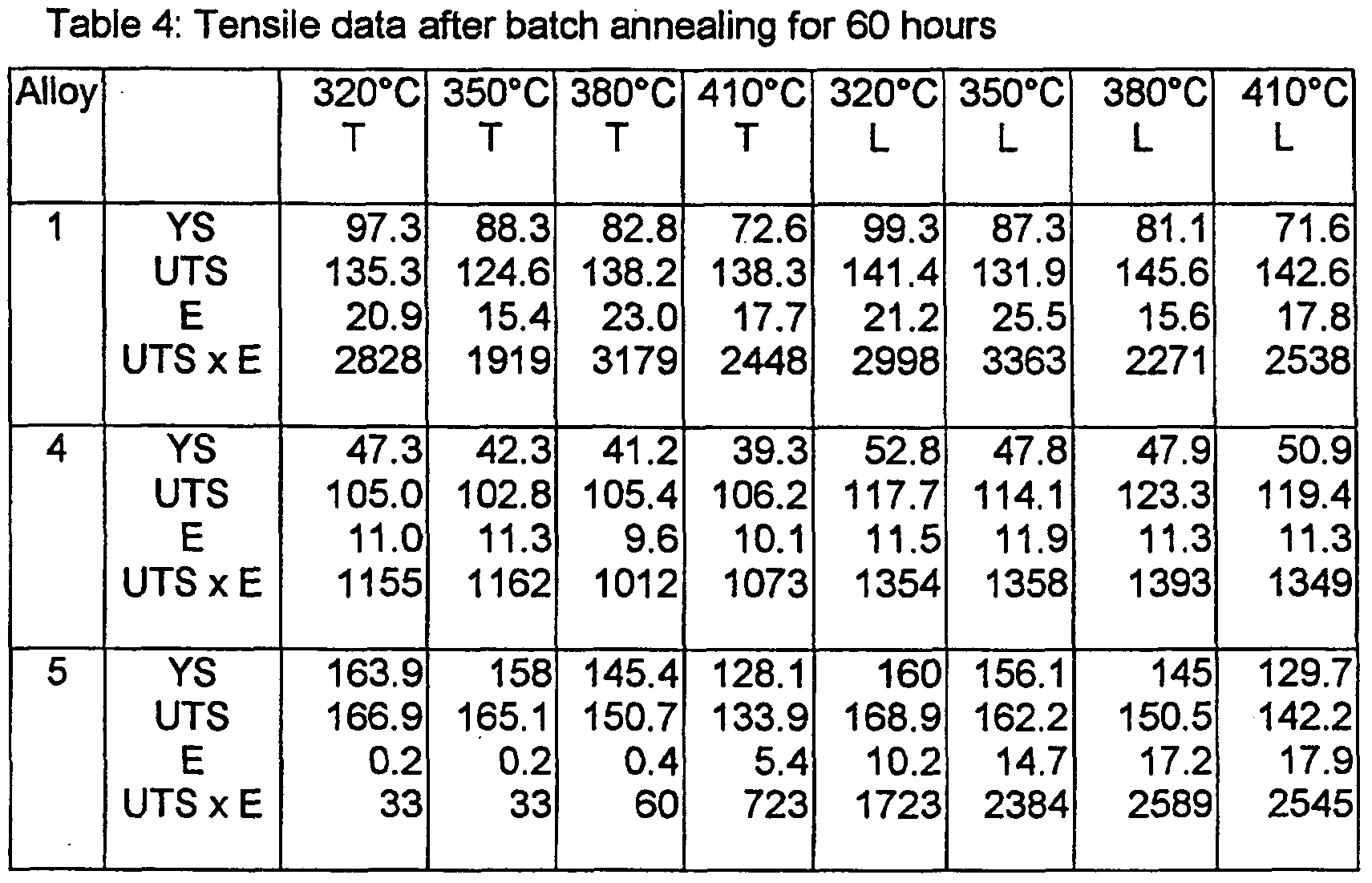
  • All alloys were continuously cast in a twin roll caster to the gauges shown in Table 1. They were then cold rolled on a lab-scale cold mill to a final gauge of 150 ⁇ m without an interannealing step. Each cold rolled product of alloys 1 , 4 and 5 was then subjected to batch annealing treatments at 320, 350, 380 and 41O 0 C for periods of 20, 40 and 60 hours. Alloy 2 was batch annealed at these temperatures for a duration of 45 hours. Alloy 5 in particular, was found to have very inconsistent mechanical properties due to a completely different tensile deformation behaviour. As mentioned above, in order to assess the balance of strength and ductility the product of UTS and elongation was calculated. The mechanical properties are shown in Tables 2, 3 and 4 and in Figures 1 to 6.
  • the inventive alloy 1 always has the better combination of UTS and elongation in the transverse direction compared with alloys 4 or 5.
  • alloy 5 is able to match the combination of UTS and elongation only when it is s annealed at high temperatures. As described above, at such temperatures there is an increased danger of uncontrolled recrystallization and coarse grain growth and this is not satisfactory from an industrial processing perspective.
  • Alloy 2, also according to the invention provides the best combination of properties; a combination that alloy 5 did not match.
  • Alloy 1 was continuously cast in a twin roll caster to the same gauge as in
  • the processing route with an interanneal at 320 0 C and the final anneal 30O 0 C 5 reflects the recommended production route from WO 02/064848.
  • the mechanical properties of alloy 1 after these treatments are given in Table 5 and Figures 8 to 13. They show there is a significant difference between the mechanical properties attainable with the current invention and the product manufactured according to WO 02/064848. 0 Table 5:
  • the YS of the interannealed version was very much inferior to the inventive method.
  • alloy 2 was continuously cast by twin roll casting to the same gauge as in Example 1 and cold rolled on an industrial cold mill to gauges of 78, and 116 ⁇ m without interanneals using conventional cold rolling pass schedules.
  • the cold rolled product of gauge 78 ⁇ m was batch annealed at 35O 0 C for 25 hours and the 116 ⁇ m gauge product was annealed at 320°C for 30 hours.
  • the mechanical test results are shown in Table 7.
  • Lab-scale cold rolling involves different thermal and strain conditions.
  • the strip In an industrial mill the strip is deformed / reduced in gauge to a greater extent through each pass. As a result its temperature rises, towards 100 0 C and above. After a pass the warm strip is coiled and the thermal mass means a coil retains heat for some time. As the temperature rises recovery can start such that recovery is taking place both during further rolling and when the metal is in a coil. Recovery taking place like this is known as dynamic recovery and, since recovery enhances ductility, explains the enhanced properties seen after industrial scale processing, especially with respect to elongation.
  • Alloys 1, 4 and 5 were cast and rolled to a final gauge in the same way as described in Example 1. They were then immersed into a hot furnace for 10 minutes at each of the following temperatures, 320, 350, 380 and 41O 0 C to simulate an industrial-scale continuous annealing line.
  • the mechanical properties in the transverse direction only are shown in Table 8 and in Figure 7. Only the transverse properties are shown because it is the transverse properties that usually represent the worst case scenario for ductility. Good ductility in the transverse direction usually corresponds to good ductility in the longitudinal direction.
  • the inventive alloy 1 always had the better balance of mechanical properties.
  • the elongation values measured here for the process of the invention are relatively low, it should be remembered that these tests were conducted on foil rolled using a lab-scale mill. Therefore they did not experience the kind of dynamic recovery process necessary to provide optimum properties. But these results do show the relative combination of properties for different alloys. Indeed, these data serve to illustrate that alloy 5 cannot be continuously annealed, rendering it a less adaptable alloy product for industrial processing in different manufacturing plants.
  • Alloy 1 was twin roll cast to a gauge of 6.05mm and then cold rolled on an industrial cold mill, without interanneal, to final gauges of 79 ⁇ m and 120 ⁇ m using conventional pass schedules. Coils of both gauges were then continuously annealed by passing them through a furnace set at a temperature of 499°C. For the 120 ⁇ m gauge material this meant a strip speed of 125m/min and a duration within the furnace of around 8 seconds. For the 79 ⁇ m gauge foil the strip speed was 160m/min giving a duration within the furnace of around 6 seconds.
  • Table 9 The mechanical properties are shown in Table 9.
  • the product at 120 ⁇ m gauge was then successfully formed into deep drawn, smooth-walled containers with no sign of any surface blackening. Likewise, the 79 ⁇ m gauge product was formed into wrinkle-wall containers with no sign of surface blackening.

Landscapes

  • Chemical & Material Sciences (AREA)
  • Engineering & Computer Science (AREA)
  • Mechanical Engineering (AREA)
  • Materials Engineering (AREA)
  • Metallurgy (AREA)
  • Organic Chemistry (AREA)
  • Crystallography & Structural Chemistry (AREA)
  • Thermal Sciences (AREA)
  • Physics & Mathematics (AREA)
  • Continuous Casting (AREA)
  • Metal Rolling (AREA)
  • Laminated Bodies (AREA)
  • Chemical Vapour Deposition (AREA)
  • Crystals, And After-Treatments Of Crystals (AREA)
  • Conductive Materials (AREA)
  • Silicon Compounds (AREA)
  • Containers Having Bodies Formed In One Piece (AREA)
  • Heat Treatment Of Steel (AREA)
  • Heat Treatment Of Sheet Steel (AREA)

Abstract

The present invention relates to a method of making an aluminium alloy product having a gauge below 200µm. It also relates to an aluminium alloy product having a gauge below the same value and to containers for food packaging applications made from the aluminium alloy product. The invention is a process of manufacturing an aluminium alloy comprising the following steps: continuous casting an aluminium alloy melt of the following composition, (in weight %): Fe 1.0 - 1.8, Si 0.3 - 0.8, Mn up to 0.25, other elements less than or equal to 0.05 each and less than or equal to 0.15 in total, balance aluminium, cold rolling the cast product without an interanneal step to a gauge below 200µm and final annealing the cold rolled product.

Description

ALUMINIUM FOIL ALLOY
The present invention relates to a method of making an aluminium alloy product having a gauge below 200μm. It also relates to an aluminium alloy product having a gauge below the same value and to containers for food packaging applications made from this aluminium alloy product.
Alloys of aluminium have been used for many years as a foil for household cooking purposes, food packaging and other applications. A series of alloy compositions have been developed for such uses and they include alloys based on the compositions AA8006, AA8011, AA8111, AA8014, AA8015, AA8021 and AA8079, (where these compositions are those designated by the internationally recognised standards of the Aluminum Association of America). Alloys of the 3XXX series may also be used for foil applications, alloy AA3005 for example. Alloys of the AA8079 or AA8021 type have a high Fe content and a low Si content. Alloys of the AA8011 type have a more balanced Fe and Si content and such compositional variations affect the kind of intermetallic phases formed during solidification, which in turn they affect the final annealing response.
In a continuous casting process the higher Si containing alloys are considered to reduce casting productivity because centre line segregation effects become worse at higher casting speeds.
In producing thin foil products it is usually considered that the rolled product must not become too hard otherwise it becomes difficult to roll the foil down to final gauge. For this reason, foil manufacturers typically incorporate an interannealing step to soften the cold rolled product before final cold rolling. A product, which is just cold rolled, would have high strength (due to the work hardening) but limited ductility. In order to increase ductility and thus render the products suitable for manipulation and forming, a final annealing operation is carried out, either through a batch anneal or a continuous annealing line. The essential variables are temperature and time and, largely depending on these factors, processes of recovery, recrystallization and grain growth may proceed within the cold worked product. In thin gauge products like foil, the parameters are set to ensure that a small grain-sized structure is maintained, large grains having a detrimental impact on mechanical properties.
The microstructure of a cold rolled sheet or foil consists of fine grains of a micron scale and a high density of intermetallic phases formed during solidification. The intermetallics are broken down during rolling and have a typical particle size between 0.1 and 1.5μm. This provides the main pre-requisite for an optimum annealing response. The other important metallurgical feature is the high cold rolling degree, resulting in a fine grain structure. However these grain structures are highly anisotropic. During recovery the number of dislocations is reduced and a sub-grain structure can form. With increasing time or temperature the sub-grain size gradually increases. Initially in such a case there is no appreciable change to the microstructure, with the product retaining much of its anisotropy. Whilst there is a significant drop in strength from the as-cold rolled state and an increase in ductility, the ductility may not reach the levels achieved in a partially recrystallized material.
As the temperature or time increases recrystallization begins, being the gradual formation of a new, discernible, grain structure. Retarding forces, in the form of grain boundary precipitates / intermetallics pin the grain boundaries during recrystallization to restrict grain growth. The annealing treatment may, if there is sufficient supersaturated solute within the alloy matrix, also lead to the formation of fine intermetallic dispersoids. These too help to prevent grain growth.
It is the case, for some alloys, (of the high Fe / low Si variety for example), that optimum properties can only be achieved within a narrow annealing window, usually at high annealing temperatures. These higher temperatures are necessary because the high density of sub-micron particles mean that the grain boundary pinning effect is already high. In addition, during annealing, the precipitation of intermetallic dispersoids reinforces the grain boundary pinning effect. In effect there is no continuous recrystallization reaction at the low temperature range and it might only start at around 3800C and above. Only when the dispersoids / intermetallics become coarser at higher temperatures do the pinning forces start to decline and grain reorganization is possible. However, since the temperatures for this are very high, the metal then enters a regime where the balance between the forces driving grain growth and grain boundary pinning is unstable and uncontrolled grain growth can appear suddenly.
Production routes where direct chill, (DC), casting is used are more complicated and expensive than continuous cast routes because they usually involve more processing steps, some of which are lengthy and energy intensive, such as homogenization. It is desirable, therefore, to use continuous casting initially to remove steps like homogenization and there has been substantial work in optimising alloys and processes with this in mind. But even with a continuous cast product to start with; reduction to final gauge usually involves an interannealing step, itself energy expensive and time consuming.
For most applications and application in deep drawn containers in particular, the ultimate strength of the alloy on its own is not the most important property. It is generally the case that as the strength of an alloy product increases the elongation will decline. In reality, alloy product design is always about optimising a balance of properties. A good balance in the case of deep drawn containers would be an optimum combination of strength and formability (reflected by tensile elongation). This balance can be assessed by multiplying the ultimate tensile strength (UTS) by the elongation at failure (E). In addition it is desirable for the alloy to have a good balance of properties in both the transverse and longitudinal directions because forming rarely, if ever, takes place in one dimension.
For some containers it is required that the container walls have a certain degree of stiffness. The stiffness of a material is closely related to its yield stress (YS). Therefore, good yield strength is also desirable. On the other hand if the YS is very close to the UTS an alloy product is not ideal for use in drawn containers. It is desirable that the alloy product demonstrates strain hardening during deformation because this helps to prevent necking during forming. An alloy product with a YS close to its UTS would possess different deformation characteristics with limited, if any, strain hardening.
With regard to deep drawn containers it is desirable for surface blackening to be avoided during forming operations which we have found to be related to the composition of the intermetallic phases after solidification. In addition to these qualities it is desirable, as a means of reducing alloy costs through recycling, to be able to accommodate elements such as Mn within the melt composition. Further, it is desirable, from an operational perspective, to be able to process an alloy product through different manufacturing operations to enable best use of a range of available equipment, such as batch and continuous annealing furnaces.
WO 03/069003 describes an alloy of the high Fe / low Si type produced via a continuous casting route. The alloy disclosed comprises, in weight %, Fe 1.5-1.9, Si<0.4, Mn 0.04-0.15, other elements and balance aluminium. The processing route used to make this product is to continuously cast the alloy, cold roll with an optional interanneal with a final anneal after cold rolling at between 200 and 4300C for a period of at least 30 hours. The preferred batch annealing process is a two- stage process involving a first step between 200 and 3000C and a second step between 300 and 4300C. JP-A-03153835 discloses a fin material for use in heat exchangers where the alloy composition is, in weight %, Fe 1.1-1.5, Si 0.35-0.8, Mn 0.1-0.4, balance aluminium. The alloy was semi-continuously cast into water-cooled moulds of an internal size 30x150mm, that is, on a laboratory scale. The casting was hot rolled, intermediately rolled, cold rolled with a maximum cold rolling reduction of 30% down to a thickness of 70μm. The description of intermediate rolling followed by a smaller percentage of cold reduction suggests an intermediate anneal was used. Ultimate tensile strengths between 13.0 and 14.7 kg/mm2 are reported (127 - 144MPa)1 presumably in the longitudinal direction, but no information is provided about the YS1 elongation or the transverse properties. JP-A-60200943 discloses a similar alloy having a composition of, in weight %,
Fe >1.25-1.75, Si 0.41-0.8, Mn 0.10-0.70, balance aluminium and impurities. This alloy was also developed for use as a fin material within brazed heat exchangers. The alloy was cast as an ingot, i.e. in a DC semi-continuous manner, homogenised at 5800C for 10 hours and scalped. The ingots were then hot rolled at 525°C to a gauge of 4mm and intermediate annealed at 3800C for 1 hour. They were then subjected to cold rolling down to a gauge of 0.35mm, intermediate annealed for a second time in a continuous process with a temperature of 4800C for 15 seconds and then final cold rolled to a gauge of 0.20mm (i.e. 200μm), and annealed at 2050C for 10 minutes to simulate a paint bake treatment. One specific alloy has a YS of 13.7kg/mm2, (134MPa)1 a UTS of 16kg/mm2, (157MPa), but the elongation is reduced to 9%, giving a product of UTS x elongation of 1413. The same alloy is also shown with a YS of 4.916kg/mm2, (48MPa)1 a UTS of 12.0kg/mm2, (118MPa)1 and an elongation of 34%, giving a UTS x elongation value of 4012. There is no disclosure of the transverse mechanical properties. However, the treatment of 10 minutes at 205pC is a recovery anneal. Such an anneal will retain the anisotropy of the cold working process. WO 02/064848 describes a process for manufacturing a foil product where the alloy composition is, in weight %, Fe 1.2-1.7, Si 0.4-0.8, Mn 0.07-0.20, remainder aluminium and incidental impurities. The alloy is continuously cast using a belt caster, cold rolled with an interanneal at a temperature between 280-3500C, and final annealed. The final gauge is 0.3mm, (300μm), and the final anneal was a partial anneal by way of a batch process involving heating the cold rolled product to between 250 and 3000C. After this processing route the alloy of this disclosure developed a UTS of around 125-160MPa and elongation values of between about 28 to 14.5%. Multiples of UTS and elongation can be calculated and they range from 2295 up to 3476. No data are shown concerning transverse properties or with respect to YS.
Further alloys are known and sold for food packaging applications. This includes alloys based on AA8011. AA8011 has a composition as follows, in weight %: Fe 0.6-1.0, Si 0.50-0.90, Cu <0.10, Mn <0.20, Mg <0.05, Cr <0.05, Zn <0.10, Ti <0.08, other elements <0.05 and total others <0.15, balance Al. An alloy with Fe at the lower end of this range is known, nominally Fe 0.65 and Si 0.65. This alloy is known with and without Mn and is known to be continuous cast and is used for non-demanding products like household foil. Another alloy is known with a nominal Fe content of 1.1 and Si also at 1.1. In these alloys, where the ratio of Fe to Si is 1 :1, the addition of Mn leads to an unstable annealing response at temperatures of 3200C and above. As a result Mn is avoided in such alloys.
It is an object of this invention to provide a new and economic method of manufacturing an aluminium alloy product, a method that leads to a combination of good mechanical properties in terms of the balance between strength and elongation in both longitudinal and transverse directions, which avoids the creation of blackening deposits during deep drawing operations and which provides wide processing windows for either a batch annealed or continuous annealed product. It is a further object of this invention to provide aluminium alloy products displaying an enhanced combination of properties particularly useful in the manufacture of deep-drawn containers thereby being easy to form and not prone to surface blackening defects.
Accordingly a first aspect of the invention is a process of manufacturing an aluminium alloy product comprising the following steps:
(a) continuous casting an aluminium alloy melt of the following composition, (in weight %):
Fe 1.0 - 1.8 Si 0.3 - 0.8 Mn up to 0.25 other elements less than or equal to 0.05 each and less than or equal to 0.15 in total balance aluminium
(b) cold rolling the cast product without an interanneal step to a gauge below 200μm
(c) final annealing the cold rolled product
The alloy composition is chosen to create the appropriate balance of intermetallics after solidification, control their size distribution (and hence effect on the annealing reaction), all of which determines the final microstructure and hence the property balance. By combining the alloy composition with this process route a microstructure is developed which has a good balance between the forces driving grain boundary mobility and the retarding forces necessary to stabilise the grain size. This balance is stable over a wider range of annealing conditions leading to greater flexibility in manufacturing operations. This is because the supersaturated solute of Fe and Mn (which leads to dispersoid formation during annealing) and the intermetallic particles from the cast structure both act as retarding forces against grain coarsening. In addition to this, it is possible to achieve high isotropic YS1 UTS and elongation values and to reduce surface blackening during forming operations.
The composition of the alloy is described, in particular with respect to other elements and the balance aluminium, in the same way as recognized by the Aluminum Association Register of International Alloy Designations and Chemical Composition Limits for Wrought Aluminum and Wrought Aluminum Alloys.
Fe is added to provide mechanical strength although, because the structure is dependent on the kind of intermetallics and dispersoids formed, its content should preferably be considered together with the Mn and Si content. If the Fe content is too low the resulting mechanical strength will be too low. If the Fe content is too high it will promote coarse intermetallic phases to appear and these phases can be detrimental to the surface quality of drawn containers. Preferred embodiments are that the amount of Fe present is between 1.1 and 1.7 weight %, and more preferably between 1.2 and 1.6 weight %.
The presence of Si helps reduce the solid solution of Fe and Mn, enabling continuous recrystallization to start within a low temperature annealing range. The addition of Si in combination with Fe helps promote the formation of cubic α- AI(FeMn)Si phase and it has been found that a predominance of this phase instead of the Si-free AI(FeMn) or of the monoclinic β-form of AIFeSi helps avoid smut formation and blackening during deep drawing. It is a preferred feature of the invention that the predominant intermetallic phase present be cubic α- AI(FeMn)Si. If the Si content is too low the precipitates will be of the binary AIFe type. If the Si content reaches close to parity with the Fe content, as with the balanced AA8011 type alloys mentioned above, the α-phase is less likely to form and, instead, the β-form of AIFeSi will be formed.
It is believed that the cubic α-phase has a better adhesion to the matrix compared with the monoclinic β-form or AlM(FeMn) phases, (M = 4-6), and that, during forming, is less likely to detach. As a result the cubic α-phase is less likely to stick to the die surface and cause damage to the aluminium surface. An alternative hypothesis is that the shape of the cubic α-phase during and after cold working has an effect. Because it is more rounded than the angular monoclinic β- form, fewer aluminium fines are generated during rolling and other forming operations. Fewer fines result in reduced surface damage. In order to promote the formation of the cubic α-phase, therefore, Si is present within the range 0.3 to 0.8 weight %, preferably within the range 0.4 to 0.7 weight %, and more preferably from 0.5 to 0.7 weight %. The Fe:Si ratio is preferably between 1.5 and 5, more preferably between 1.5 and 3.
Mn also promotes the formation of the cubic α-AIFeSi phase. In addition, Mn provides a small strengthening effect. If the Mn content is too high segregation problems will be encountered within the continuously cast product and the cast product would have to be homogenized. For this reason, if present, Mn is present in an amount up to 0.25%. Since it is desirable to be able to use recycled scrap and to gain the benefit of promoting the appropriate phase formation, it is preferred that Mn is present in an amount above 0.05 weight %. It is further preferred that Mn be present in an amount between 0.05 and 0.20 weight %. Although the continuous casting can be carried out in a variety of ways including belt casting, a preferred method is to employ twin roll casting. A preferred thickness of the cast product is between 2 and 10mm, more preferably between 3 and 8mm.
With regard to step (b), preferred embodiments are that the final gauge after cold rolling be below 180μm, more preferably below 165μm. It is preferred that the gauge be above 35μm, more preferably above 60μm, more particularly where the intended application is in food packaging containers.
With regard to step (c), the final annealing may be performed by a batch process or by a continuous annealing process. The final annealing process establishes the final balance of mechanical properties for the aluminium strip product. As explained above it is important during this stage to be able to control the recovery / recrystallization reaction taking place within the cold worked metal. In reality, with this alloy and the inventive process it is possible to use a wide range of annealing conditions and achieve good mechanical properties. In the event a batch process is used, the temperature of the anneal is between
300 and 4200C. The product according to the invention is so stable during annealing that the duration can be very long, with times of up to 60 hours and more being possible, this duration being inclusive of both the slow heat up to temperature and the hold at temperature. However, since an excellent combination of properties can be achieved at shorter annealing durations and because of a desire to minimize energy costs, it is preferred that the duration of the batch anneal be between 10 and 45 hours.
In the event a continuous anneal is used the temperature of the annealing treatment is between 400 and 5200C, preferably between 450 and 5200C. The duration the strip spends within the furnace is much shorter, usually of the order of seconds, for instance between 4 and 10 seconds, and is usually adjusted to bring about the necessary microstructural transformation during the annealing step. Continuous annealing on an industrial line can be simulated by immersing samples into furnaces set at lower temperatures but for longer durations.
The skilled person will understand that there is a range of factors to consider in controlling the continuous annealing operation. For example one might vary the speed of the metal through the furnace depending on the gauge of the strip, the heat transfer conditions within the furnace (which can vary from furnace to furnace depending on the movement of air within the furnace) and the maximum set furnace temperatures. Establishing optimum conditions for each continuous annealing line is an established practice within the industry. With this invention it is possible to operate the continuous annealing line with a wide range of settings and achieve the same results.
Following this process route it is possible to obtain an improved alloy product compared with the prior art alloy products mentioned above.
A second aspect of the invention is an aluminium alloy product having a gauge below 200μm and comprising the following alloy composition in weight %: Fe 1.0 - 1.8 Si 0.3 - 0.8 Mn up to 0.25 other elements less than or equal to 0.05 each and less than or equal to 0.15 in total balance aluminium wherein the aluminium alloy product possesses the following properties: in the transverse direction: a yield stress >100MPa a UTS >130MPa an elongation > 19%, and a product of UTS x elongation >2500 and in the longitudinal direction: a yield stress >100MPa UTS >140MPa an elongation >18%, and a product of UTS x elongation >2500.
The alloy product of the second aspect of the invention is obtainable by the process of the first aspect of the invention.
The same matters with regard to intermetallic phases and their influence on the annealing reaction of the product should be borne in mind and therefore the composition may be more preferably controlled in the same way as described above. With regard to the mechanical properties it is preferred that the transverse yield stress is >110MPa, more preferably >120MPa and it is preferred that the longitudinal yield strength is >110MPa, more preferably >120MPa.
It is preferred that the transverse UTS be greater than 135MPa1 more preferably >140MPa. It is preferred that the longitudinal UTS be greater than 150MPa.
The transverse elongation for the inventive alloy product is preferred to be above 20% and more preferred to be 22%. The longitudinal elongation is preferred to be above 19% and more preferred to be above 20%.
For the product of ultimate tensile strength and elongation, for the transverse direction this is preferably >3000 and, in the longitudinal direction, it is preferred if this product is >3000. The process and product according to invention has a very useful balance of properties and adaptability such that its use can be contemplated within a wide range of typical foil applications including but not limited to, deep drawn containers, smooth-walled or wrinkle-walled containers and household cooking foil.
The invention will now be illustrated by reference to the following examples, tables and figures. EΞxamples 1 to 3 relate to batch annealing in the final anneal and Examples 4 and 5 relate to continuous annealing in the final anneal. All mechanical tests were carried out according to DIN-EN 10002. The YS and UTS values are always stated in MPa and elongation (E) as a percentage. "T" refers to the transverse direction, "L" to the longitudinal. All alloy contents are expressed in weight %.
Example 1
Table 1 summarises the alloy compositions investigated. Alloys 1 and 2 are alloys within the scope of the invention. Alloy 4 is an AA8011 type alloy with Fe towards the lower end of the composition range, i.e. similar to products commercially available, but with an addition of Mn. Alloy 5 is an alloy according to the prior art WO 03/069003. For each composition the other elements were <0.05 each and 0.15 in total with the balance Al.
All alloys were continuously cast in a twin roll caster to the gauges shown in Table 1. They were then cold rolled on a lab-scale cold mill to a final gauge of 150μm without an interannealing step. Each cold rolled product of alloys 1 , 4 and 5 was then subjected to batch annealing treatments at 320, 350, 380 and 41O0C for periods of 20, 40 and 60 hours. Alloy 2 was batch annealed at these temperatures for a duration of 45 hours. Alloy 5 in particular, was found to have very inconsistent mechanical properties due to a completely different tensile deformation behaviour. As mentioned above, in order to assess the balance of strength and ductility the product of UTS and elongation was calculated. The mechanical properties are shown in Tables 2, 3 and 4 and in Figures 1 to 6.
Figure imgf000013_0001
Figure imgf000013_0002
Figure imgf000014_0001
Figure imgf000014_0002
As can be seen, in Figures 1, 3 and 5, the inventive alloy 1 always has the better combination of UTS and elongation in the transverse direction compared with alloys 4 or 5. In the longitudinal direction, (as shown by Figures 2, 4 and 6), alloy 5 is able to match the combination of UTS and elongation only when it is s annealed at high temperatures. As described above, at such temperatures there is an increased danger of uncontrolled recrystallization and coarse grain growth and this is not satisfactory from an industrial processing perspective. Alloy 2, also according to the invention, provides the best combination of properties; a combination that alloy 5 did not match. These results show that the process o according to the invention provides a superior product and enables manufacturers to choose from a wider range of annealing conditions.
Example 2
5 Alloy 1 was continuously cast in a twin roll caster to the same gauge as in
Table 1 and then cold rolled on a lab-scale cold mill to a gauge of 1.5mm. At this point, some samples were subject to an interanneal and others were not. For those interannealed, the heat up rate was 500C per hour and they were held at a temperature of 32O0C for 4 hours. They were then air-cooled. All samples were 0 then cold rolled to a final gauge of 210μm. Samples of the cold rolled product, with and without the interanneal, were subjected to four final batch annealing treatments. All the anneals were for a duration of 4 hours and at temperatures of 250, 300 and 3500C.
The processing route with an interanneal at 3200C and the final anneal 30O0C 5 reflects the recommended production route from WO 02/064848. The mechanical properties of alloy 1 after these treatments are given in Table 5 and Figures 8 to 13. They show there is a significant difference between the mechanical properties attainable with the current invention and the product manufactured according to WO 02/064848. 0 Table 5:
Figure imgf000016_0001
The mechanical properties of alloy 1 after processing according to WO 02/064848 are always lower than the new inventive method in both longitudinal and transverse directions. In particular, the YS for the interannealed samples was considerably lower when the final anneal was 3000C and above.
To investigate the effect of interannealing on properties after continuous annealing, samples of alloy 1 processed in the same way as described in this Example above to a gauge of 210m, with and without interanneal, were immersed in a furnace at 350C for 10 minutes to simulate a continuous anneal. The transverse properties are shown in Table 6.
Table 6:
Figure imgf000016_0002
As with the batch annealing, the YS of the interannealed version was very much inferior to the inventive method.
Example 3
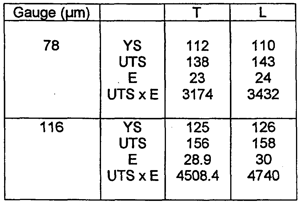
In order to demonstrate the typical level of properties achievable on an industrial scale and at different gauges, alloy 2 was continuously cast by twin roll casting to the same gauge as in Example 1 and cold rolled on an industrial cold mill to gauges of 78, and 116μm without interanneals using conventional cold rolling pass schedules. The cold rolled product of gauge 78μm was batch annealed at 35O0C for 25 hours and the 116μm gauge product was annealed at 320°C for 30 hours. The mechanical test results are shown in Table 7.
Table 7:
Figure imgf000017_0001
Whilst Examples 1 and 2 illustrate the relative advantages of the inventive process as applied to alloys 1 and 2 over the prior art, this Example illustrates the kind of properties attainable in full industrial production.
Lab-scale cold rolling, as used in Examples 1 and 2, involves different thermal and strain conditions. In an industrial mill the strip is deformed / reduced in gauge to a greater extent through each pass. As a result its temperature rises, towards 1000C and above. After a pass the warm strip is coiled and the thermal mass means a coil retains heat for some time. As the temperature rises recovery can start such that recovery is taking place both during further rolling and when the metal is in a coil. Recovery taking place like this is known as dynamic recovery and, since recovery enhances ductility, explains the enhanced properties seen after industrial scale processing, especially with respect to elongation.
Example 4
Alloys 1, 4 and 5 were cast and rolled to a final gauge in the same way as described in Example 1. They were then immersed into a hot furnace for 10 minutes at each of the following temperatures, 320, 350, 380 and 41O0C to simulate an industrial-scale continuous annealing line. The mechanical properties in the transverse direction only are shown in Table 8 and in Figure 7. Only the transverse properties are shown because it is the transverse properties that usually represent the worst case scenario for ductility. Good ductility in the transverse direction usually corresponds to good ductility in the longitudinal direction.
Table 8:
Figure imgf000018_0001
As shown by these results, the inventive alloy 1 always had the better balance of mechanical properties. Although the elongation values measured here for the process of the invention are relatively low, it should be remembered that these tests were conducted on foil rolled using a lab-scale mill. Therefore they did not experience the kind of dynamic recovery process necessary to provide optimum properties. But these results do show the relative combination of properties for different alloys. Indeed, these data serve to illustrate that alloy 5 cannot be continuously annealed, rendering it a less adaptable alloy product for industrial processing in different manufacturing plants.
Example 5
Alloy 1 was twin roll cast to a gauge of 6.05mm and then cold rolled on an industrial cold mill, without interanneal, to final gauges of 79μm and 120μm using conventional pass schedules. Coils of both gauges were then continuously annealed by passing them through a furnace set at a temperature of 499°C. For the 120μm gauge material this meant a strip speed of 125m/min and a duration within the furnace of around 8 seconds. For the 79μm gauge foil the strip speed was 160m/min giving a duration within the furnace of around 6 seconds. The mechanical properties are shown in Table 9.
Table 9:
Figure imgf000019_0001
The product at 120μm gauge was then successfully formed into deep drawn, smooth-walled containers with no sign of any surface blackening. Likewise, the 79μm gauge product was formed into wrinkle-wall containers with no sign of surface blackening.
An alloy of the following composition: Fe 1.50, Si 0.60 and Mn 0.09, other elements <0.05 each and <0.15 in total, balance Al1 was twin roll cast to a gauge of 6.29mm and then cold rolled on an industrial mill to a gauge of 135μm using conventional pass schedules. It was then subjected to simulated continuous annealing treatments of 10 minutes in a furnace at 325, 350 and 375°C. The mechanical properties are shown in Table 10.
Table 10:
Figure imgf000020_0001
The results from this Example show that it is possible, with an alloy made according to the invention and on an industrial scale continuous annealing line, to achieve a very good combination of properties in both longitudinal and transverse directions. These results also show that it is possible with the alloy and process according to the invention to obtain similar properties over a wide range of gauges and strip speeds. A consistent annealing response like this is very useful for flexible manufacturing. In addition, the consistency of results when compared with the industrial scale batch annealing results of Example 3, show that the alloy and process of the invention enables highly flexible manufacturing in the sense that a producer is not limited to a single set of available heat treatment facilities but can switch from batch annealing to continuous annealing and still expect similar product characteristics.

Claims

1. A process of manufacturing an aluminium alloy product comprising the following steps: (a) continuous casting an aluminium alloy melt of the following composition, (in weight %):
Figure imgf000021_0001
Si 0.3 - 0.8
Mn up to 0.25 other elements less than or equal to 0.05 each and less than or equal to 0.15 in total balance aluminium (b) cold rolling the cast product without an interanneal step to a gauge below 200μm (c) final annealing the cold rolled product
2. A process according to claim 1 in which the continuous casting (a) takes place in a twin roll caster.
3. A process according to claims 1 or 2 in which the Fe content is 1.1 to 1.7 weight %.
4. A process according to claim 3 in which the Fe content is 1.2 to 1.6 weight %.
5. A process according to any one of claims 1 to 4 in which the Si content is 0.4 to 0.7 weight %.
6. A process according to claim 5 in which the Si content is 0.5 to 0.7 weight %.
7. A process according to any one of claims 1 to 6 in which the Fe: Si ratio is between 1.5 and 5.
8. A process according to claim 7 in which the Fe:Si ratio is between 1.5 and 3.
9. A process according to any one of claims 1 to 8 in which the predominant intermetallic phase is the cubic α-AIFeSi phase.
10. A process according to claims 1 to 9 in which the Mn content is 0.05 to 0.25 weight %.
11. A process according to claim 10 in which the Mn content is 0.05 to 0.20 weight %.
12. A process according to claim 11 in which the Mn content is 0.05 to 0.15 weight %.
13. A process according to any one of claims 1 to 12 in which the final anneal (c) is a batch anneal.
14. A process according to claim 13 in which the batch anneal is carried out within the temperature range 300 to 4200C.
15. A process according to claim 14 in which the batch anneal is carried out within the temperature range 300 to 3800C.
16. A process according to claim 15 in which the batch anneal is carried out within the temperature range 320 to 3800C.
17. A process according to any one of claims 1 to 12 in which the final anneal (c) is a continuous anneal.
18. A process according to claim 17 in which the continuous anneal is carried out within the temperature range 400 to 52O0C.
19. A process according to claim 18 in which the continuous anneal is carried out within the temperature range 450 to 5200C.
20. An aluminium alloy product having a gauge below 200μm and the following composition in weight %: Fe 1.0- 1.8
Si 0.3 - 0.8
Mn up to 0.25 other elements less than or equal to 0.05 each and less than or equal to 0.15 in total balance aluminium wherein the aluminium alloy product possesses the following properties: in the transverse direction: a yield stress >100MPa a UTS >130MPa an elongation >19, and a product of UTS x elongation >2500 in the longitudinal direction: a yield stress >100MPa a UTS >140MPa an elongation >18, and a product of UTS x elongation >2500.
21. A product according to claim 20 obtainable by the process according to any one of claims 1 to 19.
2. A deep drawn container manufactured from the alloy product of claims 20 or 21.
PCT/EP2006/006332 2005-06-29 2006-06-29 Process of producing a foil of an al-fe-si type aluminium alloy and foil thereof Ceased WO2007006426A2 (en)

Priority Applications (9)

Application Number Priority Date Filing Date Title
US11/995,023 US8206519B2 (en) 2005-06-29 2006-06-29 Aluminium foil alloy
DE602006004594T DE602006004594D1 (en) 2005-06-29 2006-06-29 ALUMINUM ALLOY FILM AND METHOD FOR THE PRODUCTION THEREOF
EP06762282.9A EP1902149B2 (en) 2005-06-29 2006-06-29 Process of producing a foil of an al-fe-si type aluminium alloy and foil thereof
ES06762282T ES2318764T5 (en) 2005-06-29 2006-06-29 Production procedure of an Al-Fe-Si type aluminum alloy sheet and sheet of the same
DK06762282.9T DK1902149T5 (en) 2005-06-29 2006-06-29 PROCEDURE FOR THE PREPARATION OF AN ALUMINUM ALLOY FILM OF THE AL-FE-SI TYPE AND ITS FILM
BRPI0613385-1A BRPI0613385B1 (en) 2005-06-29 2006-06-29 PRODUCTION PROCESS OF AN ALUMINUM ALLOY PRODUCT, ALUMINUM ALLOY PRODUCT OBTAINED BY THE PROCESS
SI200630213T SI1902149T2 (en) 2005-06-29 2006-06-29 Aluminium alloy foil and its production process
CA2610682A CA2610682C (en) 2005-06-29 2006-06-29 Process of producing a foil of an al-fe-si type aluminium alloy and foil thereof
US13/480,259 US20120230862A1 (en) 2005-06-29 2012-05-24 Aluminium foil alloy

Applications Claiming Priority (2)

Application Number Priority Date Filing Date Title
EP05014016 2005-06-29
EP05014016.9 2005-07-08

Related Child Applications (1)

Application Number Title Priority Date Filing Date
US13/480,259 Division US20120230862A1 (en) 2005-06-29 2012-05-24 Aluminium foil alloy

Publications (3)

Publication Number Publication Date
WO2007006426A2 true WO2007006426A2 (en) 2007-01-18
WO2007006426A3 WO2007006426A3 (en) 2007-07-12
WO2007006426B1 WO2007006426B1 (en) 2007-08-23

Family

ID=34937709

Family Applications (1)

Application Number Title Priority Date Filing Date
PCT/EP2006/006332 Ceased WO2007006426A2 (en) 2005-06-29 2006-06-29 Process of producing a foil of an al-fe-si type aluminium alloy and foil thereof

Country Status (11)

Country Link
US (2) US8206519B2 (en)
EP (1) EP1902149B2 (en)
CN (1) CN101248199A (en)
AT (1) ATE419405T1 (en)
BR (1) BRPI0613385B1 (en)
CA (1) CA2610682C (en)
DE (1) DE602006004594D1 (en)
DK (1) DK1902149T5 (en)
ES (1) ES2318764T5 (en)
SI (1) SI1902149T2 (en)
WO (1) WO2007006426A2 (en)

Cited By (4)

* Cited by examiner, † Cited by third party
Publication number Priority date Publication date Assignee Title
TWI425116B (en) * 2009-01-16 2014-02-01 Nippon Steel & Sumitomo Metal Corp Corrosion resistance of the molten Zn-Al-Mg-Si-Cr alloy plating steel
RU2507299C2 (en) * 2009-06-23 2014-02-20 Линде Аг Annealing of cold-rolled metallic strip
JP2016216752A (en) * 2015-05-14 2016-12-22 三菱アルミニウム株式会社 Aluminum foil and manufacturing method therefor
WO2022139717A1 (en) * 2020-12-23 2022-06-30 Assan Alümi̇nyum Sanayi̇ Ve Ti̇caret Anoni̇m Şi̇rketi̇ An aluminum alloy material suitable for use in the food industry and production method thereof

Families Citing this family (9)

* Cited by examiner, † Cited by third party
Publication number Priority date Publication date Assignee Title
CN101812617A (en) * 2010-04-22 2010-08-25 江阴博威合金材料有限公司 Air-conditioning foil applicable to stamping of various punches and manufacturing method thereof
CN102634700B (en) * 2012-05-15 2014-09-17 山东大学 Casting aluminum-silicon alloy inoculant, and preparation method and application thereof
US20140087617A1 (en) * 2012-09-27 2014-03-27 Rogers Corporation Aluminum poly(aryl ether ketone) laminate, methods of manufacture thereof, and articles comprising the same
MX2016016891A (en) * 2014-07-09 2017-06-20 Hydro Aluminium Rolled Prod Use of an aluminium alloy or of an aluminium sheet product made from an alloy of this type for an aluminium-plastic composite part.
EP3235916B1 (en) 2016-04-19 2018-08-15 Rheinfelden Alloys GmbH & Co. KG Cast alloy
JP6461248B2 (en) 2017-07-06 2019-01-30 三菱アルミニウム株式会社 Aluminum alloy foil and method for producing aluminum alloy foil
JP6461249B2 (en) * 2017-07-06 2019-01-30 三菱アルミニウム株式会社 Aluminum alloy foil and method for producing aluminum alloy foil
CN109402460B (en) * 2018-12-25 2023-06-23 江苏中基新能源科技集团有限公司 Double-zero aluminum foil for alloying SP medicine bag with high peel strength and high heat sealing strength
CN121759730A (en) * 2026-02-28 2026-03-31 广西国潮铝业有限公司 Current collector battery aluminum foil and preparation method thereof

Family Cites Families (8)

* Cited by examiner, † Cited by third party
Publication number Priority date Publication date Assignee Title
JPS60200943A (en) 1984-03-23 1985-10-11 Sumitomo Light Metal Ind Ltd Aluminum alloy having superior strength and workability
US4671985A (en) * 1984-11-05 1987-06-09 Swiss Aluminium Ltd. Thin, deformable composite laminate
JPH07820B2 (en) 1986-04-21 1995-01-11 昭和アルミニウム株式会社 Aluminum alloy foil for packaging with little springback after molding
JP2968290B2 (en) 1989-11-10 1999-10-25 三菱アルミニウム株式会社 A ▲ High-strength Al ▲ alloy fin material for heat exchange
US5503689A (en) * 1994-04-08 1996-04-02 Reynolds Metals Company General purpose aluminum alloy sheet composition, method of making and products therefrom
JP4058536B2 (en) 1997-10-31 2008-03-12 日本軽金属株式会社 Method for producing aluminum alloy foil
US6531006B2 (en) * 2001-02-13 2003-03-11 Alcan International Limited Production of high strength aluminum alloy foils
FR2836154B1 (en) * 2002-02-15 2004-10-22 Pechiney Rhenalu THIN STRIPS IN ALUMINUM-IRON ALLOY

Cited By (6)

* Cited by examiner, † Cited by third party
Publication number Priority date Publication date Assignee Title
TWI425116B (en) * 2009-01-16 2014-02-01 Nippon Steel & Sumitomo Metal Corp Corrosion resistance of the molten Zn-Al-Mg-Si-Cr alloy plating steel
US8911879B2 (en) 2009-01-16 2014-12-16 Nippon Steel & Sumitomo Metal Corporation Hot-dip Zn—Al—Mg—Si—Cr alloy-coated steel material with excellent corrosion resistance
RU2507299C2 (en) * 2009-06-23 2014-02-20 Линде Аг Annealing of cold-rolled metallic strip
JP2016216752A (en) * 2015-05-14 2016-12-22 三菱アルミニウム株式会社 Aluminum foil and manufacturing method therefor
WO2022139717A1 (en) * 2020-12-23 2022-06-30 Assan Alümi̇nyum Sanayi̇ Ve Ti̇caret Anoni̇m Şi̇rketi̇ An aluminum alloy material suitable for use in the food industry and production method thereof
US12325900B2 (en) 2020-12-23 2025-06-10 Assan Alüminyum Sanayi Ve Ticaret Anonim Sirketi Aluminum alloy material suitable for use in the food industry and production method thereof

Also Published As

Publication number Publication date
CN101248199A (en) 2008-08-20
US20110165015A1 (en) 2011-07-07
ES2318764T3 (en) 2009-05-01
EP1902149A2 (en) 2008-03-26
WO2007006426A3 (en) 2007-07-12
CA2610682C (en) 2014-05-27
DK1902149T4 (en) 2019-07-01
ATE419405T1 (en) 2009-01-15
EP1902149B1 (en) 2008-12-31
BRPI0613385B1 (en) 2014-08-12
ES2318764T5 (en) 2019-12-13
DE602006004594D1 (en) 2009-02-12
US8206519B2 (en) 2012-06-26
EP1902149B2 (en) 2019-05-22
SI1902149T1 (en) 2009-04-30
US20120230862A1 (en) 2012-09-13
DK1902149T5 (en) 2019-08-26
WO2007006426B1 (en) 2007-08-23
SI1902149T2 (en) 2019-09-30
DK1902149T3 (en) 2009-03-30
CA2610682A1 (en) 2007-01-18
BRPI0613385A2 (en) 2011-05-24

Similar Documents

Publication Publication Date Title
US20120230862A1 (en) Aluminium foil alloy
JP3194742B2 (en) Improved lithium aluminum alloy system
CN103025901B (en) Damage-tolerant aluminum materials with layered microstructures
CN100519797C (en) Al-Mg alloy sheet with excellent formability at high temperatures and high speeds and method of production of same
WO2009096622A1 (en) Magnesium alloy panel having high strength and manufacturing method thereof
JP7639270B2 (en) Aluminum alloy forgings and manufacturing method thereof
CN105593392B (en) Bendability and the excellent high-strength aluminium alloy plate of shape freezing and its manufacture method
AU2006210790B2 (en) Aluminum-zinc-magnesium-scandium alloys and methods of fabricating same
JPS63235454A (en) Method for manufacturing aluminum-based alloy flat-rolled products
JP2002348625A (en) Aluminum alloy sheet excellent in warm formability and method for producing the same
CN113474479B (en) Process for producing sheet or strip from aluminum alloys and sheet, strip or shaped parts produced therefrom
JP7639269B2 (en) Aluminum alloy forgings and manufacturing method thereof
WO2021119804A1 (en) High strength aluminum alloys
JPH0959736A (en) Aluminum alloy sheet excellent in high-speed superplastic forming and its forming method
JPH0447019B2 (en)
JPH10259441A (en) Aluminum alloy plate excellent in high-speed superplastic formability and having few cavities after forming, and method for producing the same
JP4164206B2 (en) High-strength, high-formability aluminum alloy sheet with excellent recrystallization grain refinement during high-temperature annealing
JP4152095B2 (en) Method for producing semi-molten billet of aluminum alloy for transportation equipment
JP2008062255A (en) SUPERPLASTIC MOLDING METHOD FOR Al-Mg-Si BASED ALUMINUM ALLOY SHEET HAVING REDUCED GENERATION OF CAVITY, AND Al-Mg-Si BASED ALUMINUM ALLOY MOLDED SHEET
JP7318275B2 (en) Al-Mg-Si-based aluminum alloy cold-rolled sheet and its manufacturing method, and Al-Mg-Si-based aluminum alloy cold-rolled sheet for forming and its manufacturing method
JP2026501369A (en) Method for producing 6xxx alloy sheet with excellent surface quality
JPH0570910A (en) Production of soft aluminum alloy material for welded structure
JPH0733554B2 (en) Aluminum alloy rolled sheet for forming, which has excellent resistance to stress corrosion cracking, and method for producing the same
JPH11193435A (en) Aluminum alloy foil having excellent strength and moldability and its production
JPH0959751A (en) Method for manufacturing Al-Mg alloy plate for forming

Legal Events

Date Code Title Description
121 Ep: the epo has been informed by wipo that ep was designated in this application
DPE1 Request for preliminary examination filed after expiration of 19th month from priority date (pct application filed from 20040101)
WWE Wipo information: entry into national phase

Ref document number: 2006762282

Country of ref document: EP

WWE Wipo information: entry into national phase

Ref document number: 2610682

Country of ref document: CA

NENP Non-entry into the national phase

Ref country code: DE

WWW Wipo information: withdrawn in national office

Country of ref document: DE

WWE Wipo information: entry into national phase

Ref document number: 200680024963.9

Country of ref document: CN

WWP Wipo information: published in national office

Ref document number: 2006762282

Country of ref document: EP

WWE Wipo information: entry into national phase

Ref document number: 11995023

Country of ref document: US

DPE1 Request for preliminary examination filed after expiration of 19th month from priority date (pct application filed from 20040101)
ENP Entry into the national phase

Ref document number: PI0613385

Country of ref document: BR

Kind code of ref document: A2

Effective date: 20080108