WO2007015462A1 - 高効率増幅器 - Google Patents
高効率増幅器 Download PDFInfo
- Publication number
- WO2007015462A1 WO2007015462A1 PCT/JP2006/315153 JP2006315153W WO2007015462A1 WO 2007015462 A1 WO2007015462 A1 WO 2007015462A1 JP 2006315153 W JP2006315153 W JP 2006315153W WO 2007015462 A1 WO2007015462 A1 WO 2007015462A1
- Authority
- WO
- WIPO (PCT)
- Prior art keywords
- amplifier
- phase line
- output
- electrical length
- impedance
- Prior art date
- Legal status (The legal status is an assumption and is not a legal conclusion. Google has not performed a legal analysis and makes no representation as to the accuracy of the status listed.)
- Ceased
Links
Classifications
-
- H—ELECTRICITY
- H03—ELECTRONIC CIRCUITRY
- H03F—AMPLIFIERS
- H03F3/00—Amplifiers with only discharge tubes or only semiconductor devices as amplifying elements
- H03F3/68—Combinations of amplifiers, e.g. multi-channel amplifiers for stereophonics
-
- H—ELECTRICITY
- H03—ELECTRONIC CIRCUITRY
- H03F—AMPLIFIERS
- H03F1/00—Details of amplifiers with only discharge tubes, only semiconductor devices or only unspecified devices as amplifying elements
- H03F1/02—Modifications of amplifiers to raise the efficiency, e.g. gliding Class A stages, use of an auxiliary oscillation
- H03F1/0205—Modifications of amplifiers to raise the efficiency, e.g. gliding Class A stages, use of an auxiliary oscillation in transistor amplifiers
- H03F1/0288—Modifications of amplifiers to raise the efficiency, e.g. gliding Class A stages, use of an auxiliary oscillation in transistor amplifiers using a main and one or several auxiliary peaking amplifiers whereby the load is connected to the main amplifier using an impedance inverter, e.g. Doherty amplifiers
-
- H—ELECTRICITY
- H03—ELECTRONIC CIRCUITRY
- H03F—AMPLIFIERS
- H03F3/00—Amplifiers with only discharge tubes or only semiconductor devices as amplifying elements
- H03F3/60—Amplifiers in which coupling networks have distributed constants, e.g. with waveguide resonators
Definitions
- the present invention relates to a high efficiency amplifier used for broadcasting and communication.
- An RF amplifier for broadcasting and communication is desired to amplify an RF signal linearly with high efficiency.
- an amplifier cannot achieve both high efficiency and high linearity.
- the efficiency of the amplifier increases as the power level of the input signal increases, and exhibits the characteristic that the maximum efficiency is reached when the amplifier reaches saturation.
- PAPR peak-to-average power ratio
- FIG. 14 shows the configuration of the Dono and tee amplifier as the conventional high-efficiency amplifier shown in Non-Patent Document 1, the electrical length of each part, and the respective parts when the level of the input signal is small! It is a figure which shows the impedance dance which saw.
- the Doherty amplifier shown in Fig. 14 has an input terminal 1, an input distribution circuit 2, a class A or class AB biased carrier amplifier 3, an offset phase line 4, a 90 ° phase line 5, a phase line 6, a class B or C Class-biased peak amplifier 7, offset phase line 8, 90 ° phase line 9 and output terminal 10.
- FIG. 14 also shows the impedance reference point 11 on the output side of the carrier amplifier 3, the impedance reference point 12 on the output side of the peak amplifier 7, and the output synthesis point 13 of the path distributed by the input distribution circuit 2. Is shown.
- the impedance reference point 11 on the output side of the carrier amplifier 3 has a load impedance viewed from the load side on the output side of the carrier amplifier 3.
- the impedance reference point 12 on the output side of the peak amplifier 7 is the point where the impedance is viewed at the output side of the peak amplifier 7 and the output side of the offset phase line 8 is maximized.
- FIG. 15 shows the configuration of the Dono and Tee amplifiers as the conventional high-efficiency amplifier shown in Non-Patent Document 1 above, the electrical length of each part, and the level of the input signal. It is a diagram showing the impedance seen, and the same symbols as in FIG. 14 are the same.
- the offset phase line 4 connected to the carrier amplifier 3 has an electrical length ⁇ such that the output impedance when the output side of the carrier amplifier 3 is viewed from the impedance reference point 11 on the output side of the carrier amplifier 3 is maximized.
- the offset phase line 8 connected to the peak amplifier 7 is such that the output impedance when the output side of the peak amplifier 7 is viewed from the impedance reference point 12 on the output side of the peak amplifier 7 is maximized.
- the electrical length of the 90 ° phase line 5 and 90 ° phase line 9 is 90 °
- the electrical length of the phase line 6 is 90 + 0 ⁇ .
- the RF signal input from the input terminal 1 is distributed by the input side distribution circuit 2 into two paths: a path on the carrier amplifier 3 side and a path on the peak amplifier 7 side.
- the RF signal from the input side distribution circuit 3 is input to the carrier amplifier 3, and the RF signal from the carrier amplifier 3 passes through the offset phase line 4 and the 90 ° phase line 5 and is the output combining point. Is output to 13.
- the RF signal from the input side distribution circuit 2 is input to the peak amplifier 7 via the phase line 6, and the RF signal from the peak amplifier 7 is output to the output combining point via the offset phase line 8. Is output to 13.
- the RF signal from the carrier amplifier 3 and the RF output signal from the peak amplifier 7 are combined and output.
- the class B or C biased peak amplifier 7 when the level of the input signal is small, the class B or C biased peak amplifier 7 is turned off, that is, the RF signal is not amplified, and the action of the offset phase line 8
- the output impedance of the peak amplifier 7 viewed from the impedance reference point 12 on the output side of the peak amplifier 7 is ideally infinite (open).
- the impedance reference point 12 and the output combining point 13 are directly connected and can be regarded as the same point. Therefore, the output impedance viewed from the output combining point 13 to the peak amplifier 7 side is ideal. It becomes infinite (open).
- the peak amplifier 7 subjected to class B or class C noise is turned on, that is, a state in which the RF signal is amplified. Then, the RF signals from the carrier amplifier 3 and the peak amplifier 7 are synthesized and output. At this time, the load impedances of the output side viewed from the impedance reference point 11 on the output side of the carrier amplifier 3 and the impedance reference point 12 on the output side of the peak amplifier 7 are both R.
- the carrier amplifier 3 is designed so that the saturation power is small but the efficiency is high when the load impedance is 2R, and the carrier amplifier 3 and the peak amplifier when the load impedance is a scale.
- 7 is designed so that the saturation power is large, the carrier amplifier 3 operates with high efficiency when the input signal level is small, and the carrier amplifier 3 and the peak when the input signal level is large. The amplifier 7 can be operated so as to increase the saturation power.
- FIG. 16 shows an efficiency characteristic with respect to output power of the Doherty amplifier.
- the maximum efficiency point can be reached at two points: the saturation point a as a Doherty amplifier and the point b with an output back-off of 6 dB.
- b is the first efficiency maximum point when only carrier amplifier 3 operates when the input signal level is low
- a is carrier amplifier 3 when the input signal level is high. This is the second efficiency maximum point when the peak amplifier 7 is operated.
- Non-Special Reference 1 Youngoo Yangjeonghyeon, Ha'Bumjae Shin'Bumman Kim, A Fully Matched N— Way Doherty Amplifier With Optimized Linearity ”, IEEE Trans. Microwave Theory Tech., Vol.3, pp.986-993 , Mar. 2003.
- the 90 ° phase line 5 is used on the output side of the carrier amplifier 3, so that the impedance reference point 11 on the output side of the carrier amplifier 3 can be
- the load impedance is 2R when the signal is small and R when the signal is large.
- the output back-off is greater than 6 dB, and it is impossible to reach the maximum efficiency at the operating level! /
- the present invention has been made to solve the above-described problems, and provides a high-efficiency amplifier capable of improving the efficiency at a small signal operation level in which the output back-off is larger than 6 dB. With the goal.
- a high efficiency amplifier includes an input distribution circuit that distributes an input signal to first and second paths, a carrier amplifier connected to the first path, and a connection to the second path.
- the impedance seen from the impedance reference point on the output side of the carrier amplifier is 2R + a (R is a load resistance, ⁇ is positive)
- the electrical length of the first phase line and the electrical length of the third phase line are set, and the electrical length of the second phase line is set to the electrical length of the first phase line and the third phase.
- the output cannock-off that maximizes the efficiency can be made larger than 6 dB, and the efficiency can be improved when the output back-off can be improved at a small signal operation level larger than 6 dB. It is done.
- FIG. 1 is a diagram showing the configuration of a high efficiency amplifier according to Embodiment 1 of the present invention, the electrical length of each part, and the impedance viewed from each part when the level of an input signal is small.
- FIG. 2 is a diagram illustrating a load modulation locus of a high efficiency amplifier according to the first embodiment of the present invention on a Smith chart.
- FIG. 3 is a diagram showing the configuration of the high efficiency amplifier according to Embodiment 1 of the present invention, the electrical length of each part, and the impedance viewed from each part when the level of the input signal is large.
- FIG. 4 is a diagram showing efficiency characteristics with respect to output power of the high efficiency amplifier according to the first embodiment of the present invention.
- FIG. 5 is a diagram showing the configuration of the high efficiency amplifier according to Embodiment 2 of the present invention, the electrical length of each part, and the impedance viewed from each part when the level of the input signal is small.
- FIG. 6 is a diagram showing the configuration of the high efficiency amplifier according to the second embodiment of the present invention, the electrical length of each part, and the impedance viewed from each part when the level of the input signal is large.
- FIG. 7 is a diagram showing efficiency characteristics with respect to output power of the high efficiency amplifier according to the second embodiment of the present invention.
- FIG. 8 is a diagram showing the configuration of a high efficiency amplifier according to Embodiment 3 of the present invention, the electrical length of each part, and the impedance viewed from each part when the level of the input signal is small.
- FIG. 9 is a diagram showing frequency characteristics of an isolator of a high efficiency amplifier according to Embodiment 3 of the present invention.
- FIG. 10 is a block diagram showing an internal configuration of a carrier amplifier and a peak amplifier in a high efficiency amplifier according to Embodiment 4 of the present invention.
- FIG. 11 is a diagram showing efficiency characteristics of a carrier amplifier and a peak amplifier with respect to an electrical length of a phase line in a high efficiency amplifier according to Embodiment 4 of the present invention.
- FIG. 12 is a diagram showing the configuration of a high efficiency amplifier according to Embodiment 5 of the present invention and the electrical length of each part It is.
- FIG. 13 is a diagram showing efficiency characteristics with respect to output power of the high efficiency amplifier according to the fifth embodiment of the present invention.
- FIG. 14 is a diagram showing the configuration of a Dono / Tee amplifier as a conventional high-efficiency amplifier, the electrical length of each part, and the impedance seen from each part when the level of the input signal is small.
- FIG. 15 is a diagram showing the configuration of a Dono / Tee amplifier as a conventional high-efficiency amplifier, the electrical length of each part, and the impedance seen from each part when the level of the input signal is large.
- FIG. 16 is a diagram showing efficiency characteristics with respect to output power of a Dono / Tee amplifier as a conventional high-efficiency amplifier.
- FIG. 1 is a diagram showing the configuration of the high-efficiency amplifier according to Embodiment 1 of the present invention, the electrical length of each part, and the impedance viewed from each part when the level of the input signal is small.
- the high-efficiency amplifier shown in Fig. 1 has an input terminal 1, an input distribution circuit 2, a class A or class AB biased carrier amplifier 3, an offset phase line 4, a phase line 21, a phase line 22, a class B or class C noise.
- the impedance reference point 11 on the output side of the carrier amplifier 3, the impedance reference point 12 on the output side of the peak amplifier 7, and the output of the path distributed by the input distribution circuit 2 are shown.
- a force composite point 13 is shown.
- the high-efficiency amplifier shown in FIG. 1 has the 90 ° phase line 5 of the conventional Doherty amplifier shown in FIG. 14 replaced with the phase line 21, the phase line 6 replaced with the phase line 22, and the output side of the peak amplifier 7
- a phase line 23 is added between the impedance reference point 12 and the output combining point 13, and the other configurations are the same as those shown in FIG.
- the electrical length of the offset phase line 4 is 0, the electrical length of the offset phase line 8 is 0, the electrical length of the phase line 21 is 0, the electrical length of the phase cP 1 line 22 is 0, and the electrical length of the phase line 23 is 0.
- a phase line 21 having an electrical length ⁇ is connected between the impedance reference point 11 1 on the output side of the carrier amplifier 3 and the output combining point 13, and the input distribution circuit
- Phase line 23 of electrical length ⁇ is connected between impedance reference point 12 on the side and output combining point 13.
- the phase line 21 is a phase line having an electrical length of 0 [deg] shown in the following equation (1), and is connected between the impedance reference point 11 on the output side of the carrier amplifier 3 and the output combining point 13. Is done.
- ⁇ indicates the characteristic impedance of the phase lines 21 and 23.
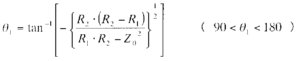
- the phase line 23 is a phase line having an electrical length ⁇ [deg] expressed by the following equation (2):
- phase line 22 is a phase line having an electrical length ⁇ [deg] shown in the following equation (3).
- the peak amplifier 7 that is biased to class C or class C is turned off, i.e., does not amplify the RF signal, and only the RF signal from the carrier amplifier 3 is the output synthesis point. Is output to 13. In this way, when the level of the input signal is small, the peak amplifier 7 is turned off, so that the output impedance of the peak amplifier 7 viewed from the impedance reference point 12 on the output side of the peak amplifier 7 is ideal. Is infinite ( ⁇ pen), and the electrical length 0 of the phase line 23 is less than 90 °.
- the 2 2 phase line 23 acts as a capacitive open stub.
- the impedance of the phase line 23 viewed from the output synthesis point 13 is converted into an impedance Z1 having a capacitive reactance whose resistance component is smaller than RZ2.
- the carrier amplifier 3 has an impedance conversion action by the phase line 21 having the electrical length ⁇ .
- the load impedance seen from the output impedance reference point 11 is converted to a real resistance 2R + a that is greater than 2R.
- FIG. 2 is a diagram illustrating a load modulation locus of a high efficiency amplifier on a Smith chart.
- the load modulation trajectory is RZ2 to 2R as shown by the dotted line in FIG. 2, whereas in the high efficiency amplifier of the first embodiment, as shown by the solid line in FIG.
- the locus of load modulation is Z1 ⁇ 2R + a.
- FIG. 3 is a diagram showing the configuration of the high-efficiency amplifier according to Embodiment 1 of the present invention, the electrical length of each part, and the impedance of each part when the level of the input signal is large.
- the reference numerals are the same.
- the peak amplifier 7 biased with class B or class C is in an on state, that is, a state in which the RF signal is amplified.
- the RF signal from amplifier 7 is synthesized and output.
- the load impedances of the output side viewed from the impedance reference point 11 on the output side of the carrier amplifier 3 and the impedance reference point 12 on the output side of the peak amplifier 7 are both R.
- the carrier amplifier 3 when the load impedance is 2R + a, the carrier amplifier 3 is designed so that the saturation power is small but the efficiency is high, and the load impedance is When the carrier amplifier 3 and the peak amplifier 7 are designed so that the saturation power is large when R, the carrier amplifier 3 operates at a high efficiency when the input signal level is small, and the input signal level When is large, the carrier amplifier 3 and the peak amplifier 7 can be operated so as to increase the saturated power.
- this Embodiment 1 can realize a highly efficient operation in a state where the output back-off from the saturation point is large.
- FIG. 4 is a diagram showing efficiency characteristics with respect to output power of the high efficiency amplifier.
- the conventional Dono and Tee amplifiers are compared with the high efficiency amplifier of the first embodiment.
- the impedance viewed from the output impedance reference point 11 of the carrier amplifier 3 is the real resistance. Since the transition from 2R + a (a is positive) to R, as shown in Fig. 4, the output backoff is larger than the point b of the output backoff 6dB in addition to the saturation point a as a Doherty amplifier. 6 + ⁇ ) ⁇ ( ⁇ is positive) It becomes possible to reach the maximum efficiency point c.
- the impedance viewed from the impedance reference point 11 on the output side of the carrier amplifier 3 as viewed from the output side is set to the impedance 2R of the conventional Doherty amplifier. Therefore, the maximum efficiency point for the first time should be set to the point c of the small signal level where the output back-off is larger than the point b of 6 dB of the output back-off of the conventional Dono-tee amplifier. Is possible. That is, in the first embodiment, high efficiency at a small signal operation level with an output back-off greater than 6 dB becomes more effective, and high efficiency can be achieved.
- the offset phase line 4 is connected to the output side of the carrier amplifier 3 and the offset phase line 8 is connected to the output side of the peak amplifier 7.
- the above equation (3) becomes the following equation (4).
- the input distribution circuit 2 distributes the input signal to two paths (first and second paths), connects the carrier amplifier 3 to one path, and the other
- the peak amplifier 7 is connected to the path of
- the 90 ° phase line (impedance conversion circuit) 9 is connected to the output combining point 13 of the two paths
- a phase line (first phase line) 21 is connected between 13
- a phase line (second phase line) 22 is connected between the input distribution circuit 2 and the peak amplifier 7, and the output side of the peak amplifier 7
- the phase line 21 having the electrical length ⁇ is connected between the impedance reference point 11 on the output side of the carrier amplifier 3 and the output combining point 13, and the input distribution is performed.
- a phase line 22 of electrical length ⁇ is connected between the circuit 2 and the peak amplifier 7, and the peak amplifier 7
- the electrical length 0 of the phase line 21 and the phase line 23 are set so that the impedance viewed from the impedance reference point 11 on the output side of the carrier amplifier 3 is 2R + a.
- the maximum output can knock-off can be greater than 6 dB, the output back-off is greater than 6 dB, and the efficiency can be improved for small signal operation levels.
- FIG. 5 is a diagram showing the configuration of the high efficiency amplifier according to Embodiment 2 of the present invention, the electrical length of each part, and the impedance of each part when the level of the input signal is small.
- the high-efficiency amplifier shown in FIG. 5 is obtained by adding a phase line (fourth phase line) 24 to the high-efficiency amplifier shown in FIG. 1 of the first embodiment, and the other configurations are the same as those in FIG. .
- FIG. 6 shows the configuration of the high efficiency amplifier according to Embodiment 2 of the present invention and the electrical length of each part. It is a figure which shows the impedance seen from each part in case the level of an input signal is large.
- the high-efficiency amplifier shown in FIG. 6 is obtained by adding a phase line 24 to the high-efficiency amplifier shown in FIG. 3 of the first embodiment, and the other configurations are the same as those in FIG.
- the phase line 24 is a phase line having an electrical length ⁇ [deg] shown in the following equation (5), and is connected between the input distribution circuit 3 and the peak amplifier 6.
- ⁇ is the electrical length of the carrier amplifier 3
- ⁇ is the electrical length of the peak amplifier 7.
- the peak amplifier 7 that is biased to class B or class C is in an on state, that is, a state in which the RF signal is amplified.
- the RF signal from the amplifier 7 is synthesized and output.
- the difference ⁇ between the electrical length ⁇ of the carrier amplifier 3 that is class-class or class-classically biased and the electrical length ⁇ of the peak amplifier 7 that is class B or class C-noised is
- the RF signals from the carrier amplifier 3 and the peak amplifier 7 can be synthesized in the same phase at the output synthesis point 13. For this reason, the RF signal synthesis efficiency is improved in the region where the input signal level is high.
- FIG. 7 shows the efficiency characteristic with respect to the output power of the high efficiency amplifier.
- the conventional Doherty amplifier, the high efficiency amplifier of the first embodiment, and the high efficiency amplifier of the second embodiment are compared.
- the RF signal synthesis efficiency in the region where the level of the input signal is large is improved, and as a result, the high efficiency of the amplifier is improved. It is possible to make a habit.
- the offset phase line 4 is connected to the output side of the carrier amplifier 3 and the offset phase line 8 is connected to the output side of the peak amplifier 7.
- the offset phase line 4 and the offset phase line 8 may be deleted.
- the same effect as in the first embodiment can be obtained. Further, by correcting the difference between the electrical length ⁇ of the carrier amplifier 3 and the electrical length ⁇ of the peak amplifier 7 by the phase line 24 connected to the input side of the peak amplifier 7,
- FIG. 8 is a diagram showing the configuration of the high efficiency amplifier according to Embodiment 3 of the present invention, the electrical length of each part, and the impedance of each part when the level of the input signal is small.
- the high efficiency amplifier shown in FIG. 8 is obtained by adding an isolator 31 having a characteristic impedance R to the output side of the 90 ° phase circuit 9 in the high efficiency amplifier shown in FIG. Is the same as in Figure 1.
- FIG. 9 is a diagram showing the frequency characteristics of the isolator 31. As shown in FIG. 9, the isolator 31 has a frequency 2f that is a harmonic of the RF signal, for example, twice the frequency f of the RF signal.
- the offset phase line 4 is connected to the output side of the carrier amplifier 3, and the offset phase line 8 is connected to the output side of the peak amplifier 7.
- the offset phase line 4 and the offset phase line 8 may be deleted.
- an effect similar to that of the first embodiment can be obtained, and an isolator 31 having a characteristic impedance R can be provided on the output side of the 90 ° phase circuit 9.
- FIG. 10 is a block diagram showing the internal configuration of carrier amplifier 3 and peak amplifier 7 in the high efficiency amplifier according to Embodiment 4 of the present invention.
- Carrier amplifier 3 shown in Figure 10 The peak amplifier 7 includes an input terminal 41, a fundamental matching circuit 42, a power supply terminal 43, a noise circuit 44, a transistor (amplifying element) 45, a phase line (fifth phase line) 46, a power supply terminal 47, capacitors 48, 90. ° Phase line 49, fundamental wave matching circuit 50, and output terminal 51 are provided.
- the bias voltage from the power supply terminal 43 is supplied to the input side of the transistor 45 via the bias circuit 44.
- the capacitor 48 and the 90 ° phase line 49 constitute a bias circuit on the output side of the transistor 45, and the bias voltage from the power supply terminal 47 is connected to the transistor 45 via the phase line 49 and the phase line 46. Supplied to the output side.
- the RF signal input from the input terminal 41 is amplified by the transistor 45 via the fundamental wave matching circuit 42 and output from the output terminal 51 via the phase line 46 and the fundamental wave matching circuit 50.
- Capacitor 48 is sufficiently small at the frequency f of the RF signal!
- the 90 ° phase line 49 and the power supply terminal 47 are short at the frequency f of the RF signal.
- phase line 49 is RF signal frequency f and electrical length is 90 °
- the electrical length is 180 ° at the frequency 2f, which is twice the RF signal.
- phase line 46 Short between the phase line 46 and the 90 ° phase line 49 at a frequency 2f that is twice the RF signal.
- a point is formed.
- Impedance ZL (2f) at wave number 2f changes.
- amplifier efficiency is double
- the efficiency of the rear amplifier 3 and the peak amplifier 7 can be maximized.
- FIG. 11 shows the carrier amplifier 3 and the peak amplifier 7 with respect to the electric length 0 of the phase line 46.
- the efficiency E of the amplifier 7 can be obtained.
- the efficiency of the entire high efficiency amplifier can be maximized, the output back-off is large, and even at a small signal level. Efficiency can be improved.
- the same effects as those of the first embodiment can be obtained, and the bias voltages of the transistors 45 of the carrier amplifier 3 and the peak amplifier 7 can be changed with respect to the RF signal.
- 90 ° phase line 49 which is a short-circuited stub with an electrical length of 90 ° at frequency f
- phase line 46 Is supplied via the phase line 46, and the electrical length ⁇ of the phase line 46 is set to a frequency 2f that is twice the RF signal.
- FIG. 12 is a diagram showing the configuration of the high efficiency amplifier according to the fifth embodiment of the present invention and the electrical length of each part.
- the high-efficiency amplifier shown in FIG. 12 is the same as the high-efficiency amplifier shown in FIG. 1 of Embodiment 1 above, but is connected to the gate voltage generation circuit 61, the drain voltage generation circuit 62, and the peak amplifier 7 connected to the carrier amplifier 3.
- a gate voltage generation circuit 63 and a drain voltage generation circuit 64 are added, and other configurations are the same as those in FIG.
- the carrier amplifier 3 and the peak amplifier 7 use transistors (not shown) having the same saturation power when the same bias voltage is supplied.
- the bias voltage Vdl supplied from the drain voltage generation circuit 62 to the transistor of the carrier amplifier 3 is set smaller than the bias voltage Vd2 supplied from the drain voltage generation circuit 64 to the transistor of the peak amplifier 7. Therefore, the saturation power of the carrier amplifier 3 is smaller than the saturation power of the peak amplifier 7, and the maximum efficiency point can be reached at a larger output back-off point than in the first embodiment.
- FIG. 13 is a diagram showing efficiency characteristics with respect to output power of the high efficiency amplifier.
- the high efficiency amplifier of the first embodiment and the high efficiency amplifier of the fifth embodiment are compared.
- the output back-off (6 + j8 + ⁇ ) dB (j8) is larger than the point c of the output back-off (6 + j8) dB in addition to the saturation point a as a Dono and tee amplifier.
- ⁇ is positive
- V can reach the maximum efficiency point d.
- the noise voltage Vdl supplied to the drain of the transistor of the carrier amplifier 3 is smaller than the noise voltage Vd 2 supplied to the drain of the transistor of the peak amplifier 7.
- the output cannock-off for maximizing the efficiency can be made larger than 6 dB compared to the first embodiment, the output back-off is larger than 6 dB, and the efficiency can be further improved with the small signal operation level. If it can be improved, the effect can be obtained.
- the high-efficiency amplifier according to the present invention has, for example, an output back-off that maximizes the efficiency greater than 6dB, and the output back-off is less than 6dB. Suitable for things that improve!
Landscapes
- Engineering & Computer Science (AREA)
- Power Engineering (AREA)
- Amplifiers (AREA)
- Microwave Amplifiers (AREA)
Abstract
Description

Claims
Priority Applications (4)
| Application Number | Priority Date | Filing Date | Title |
|---|---|---|---|
| EP06782031A EP1912328B1 (en) | 2005-08-01 | 2006-07-31 | Highly efficient amplifier |
| JP2007529258A JPWO2007015462A1 (ja) | 2005-08-01 | 2006-07-31 | 高効率増幅器 |
| CN2006800265542A CN101228689B (zh) | 2005-08-01 | 2006-07-31 | 放大器 |
| US11/921,504 US7649412B2 (en) | 2005-08-01 | 2006-07-31 | High efficiency amplifier |
Applications Claiming Priority (2)
| Application Number | Priority Date | Filing Date | Title |
|---|---|---|---|
| JP2005-222986 | 2005-08-01 | ||
| JP2005222986 | 2005-08-01 |
Publications (1)
| Publication Number | Publication Date |
|---|---|
| WO2007015462A1 true WO2007015462A1 (ja) | 2007-02-08 |
Family
ID=37708742
Family Applications (1)
| Application Number | Title | Priority Date | Filing Date |
|---|---|---|---|
| PCT/JP2006/315153 Ceased WO2007015462A1 (ja) | 2005-08-01 | 2006-07-31 | 高効率増幅器 |
Country Status (6)
| Country | Link |
|---|---|
| US (1) | US7649412B2 (ja) |
| EP (1) | EP1912328B1 (ja) |
| JP (1) | JPWO2007015462A1 (ja) |
| KR (1) | KR100957895B1 (ja) |
| CN (1) | CN101228689B (ja) |
| WO (1) | WO2007015462A1 (ja) |
Cited By (8)
| Publication number | Priority date | Publication date | Assignee | Title |
|---|---|---|---|---|
| KR100862056B1 (ko) | 2007-08-06 | 2008-10-14 | (주) 와이팜 | 광대역 전력 증폭 장치 |
| JP2010245705A (ja) * | 2009-04-02 | 2010-10-28 | Nippon Telegr & Teleph Corp <Ntt> | 高効率増幅器 |
| WO2011046031A1 (ja) * | 2009-10-13 | 2011-04-21 | 日本電気株式会社 | 電力増幅器およびその動作方法 |
| US10411653B2 (en) | 2016-11-24 | 2019-09-10 | Murata Manufacturing Co., Ltd. | Power amplifier |
| WO2021220338A1 (ja) * | 2020-04-27 | 2021-11-04 | 三菱電機株式会社 | ドハティ増幅器 |
| DE112019007058T5 (de) | 2019-04-23 | 2021-12-30 | Mitsubishi Electric Corporation | Doherty-Verstärker und Kommunikationsvorrichtung |
| DE112019007283T5 (de) | 2019-06-07 | 2022-02-03 | Mitsubishi Electric Corporation | Doherty-verstärker |
| US12231089B2 (en) | 2020-06-01 | 2025-02-18 | Murata Manufacturing Co., Ltd. | Control circuit |
Families Citing this family (18)
| Publication number | Priority date | Publication date | Assignee | Title |
|---|---|---|---|---|
| DE102007046340B4 (de) | 2007-09-27 | 2025-01-02 | Apple Inc. | Verfahren und Vorrichtung zum Regeln eines Leistungsverstärkers |
| JP5234006B2 (ja) * | 2007-11-21 | 2013-07-10 | 富士通株式会社 | 電力増幅器 |
| KR101691418B1 (ko) * | 2009-05-15 | 2017-01-02 | 삼성전자주식회사 | 도허티 증폭기에서 피킹 증폭기의 성능을 최적화시키기 위한 장치 및 방법 |
| US8115546B2 (en) * | 2009-05-15 | 2012-02-14 | Samsung Electronics Co., Ltd. | Apparatus and method for maximizing performance of peaking amplifier in doherty amplifier |
| KR101709347B1 (ko) * | 2009-12-16 | 2017-03-09 | 삼성전자주식회사 | 결합셀 도허티 전력 증폭 장치 및 방법 |
| KR101101515B1 (ko) * | 2010-02-03 | 2012-01-05 | 삼성전기주식회사 | 전력 증폭기 |
| KR101677555B1 (ko) * | 2010-02-25 | 2016-11-21 | 삼성전자주식회사 | 도허티 증폭기에서 낮은 전력 영역에서의 효율을 향상시키기 위한 장치 |
| US9007142B1 (en) * | 2011-08-02 | 2015-04-14 | Anadigics, Inc. | Integrated output combiner for amplifier system |
| EP2806557B1 (en) | 2013-05-23 | 2017-03-08 | Ampleon Netherlands B.V. | Doherty amplifier |
| CN103684271A (zh) * | 2013-11-22 | 2014-03-26 | 小米科技有限责任公司 | 提高射频功率放大器效率的装置和方法 |
| JP5833094B2 (ja) * | 2013-12-26 | 2015-12-16 | 株式会社東芝 | 電力増幅装置、及び電力増幅装置の制御方法 |
| KR101694709B1 (ko) * | 2016-02-04 | 2017-01-10 | 포항공과대학교 산학협력단 | 오프셋 라인의 길이 조절을 이용한 도허티 증폭기의 효율 향상 회로 |
| US10211785B2 (en) * | 2016-12-29 | 2019-02-19 | Nxp Usa, Inc. | Doherty amplifiers with passive phase compensation circuits |
| WO2018151020A1 (ja) * | 2017-02-17 | 2018-08-23 | パナソニックIpマネジメント株式会社 | 高周波増幅器 |
| JP2019057809A (ja) * | 2017-09-20 | 2019-04-11 | 株式会社東芝 | 増幅器及び送信機 |
| WO2019142354A1 (ja) * | 2018-01-22 | 2019-07-25 | 三菱電機株式会社 | 増幅器 |
| JP7298700B2 (ja) * | 2019-02-13 | 2023-06-27 | 日本電気株式会社 | ドハティ電力増幅器 |
| JP7337270B2 (ja) | 2020-06-04 | 2023-09-01 | 三菱電機株式会社 | ドハティ増幅器 |
Citations (4)
| Publication number | Priority date | Publication date | Assignee | Title |
|---|---|---|---|---|
| JP2000196387A (ja) * | 1998-12-28 | 2000-07-14 | Nec Corp | マイクロ波増幅回路 |
| WO2001091282A2 (en) | 2000-05-26 | 2001-11-29 | D.S.P.C. Technologies Ltd. | Rf power amplifier and methods for improving the efficiency thereof |
| JP2003188651A (ja) * | 2001-12-13 | 2003-07-04 | Ntt Docomo Inc | 高効率増幅器 |
| JP2004503161A (ja) * | 2000-07-07 | 2004-01-29 | テレフオンアクチーボラゲツト エル エム エリクソン | 複合増幅器を有する送信機 |
Family Cites Families (12)
| Publication number | Priority date | Publication date | Assignee | Title |
|---|---|---|---|---|
| US5420541A (en) * | 1993-06-04 | 1995-05-30 | Raytheon Company | Microwave doherty amplifier |
| CA2204409A1 (en) * | 1995-11-30 | 1997-05-31 | James Frank Long | Amplifier circuit and method of tuning the amplifier circuit |
| US6472934B1 (en) * | 2000-12-29 | 2002-10-29 | Ericsson Inc. | Triple class E Doherty amplifier topology for high efficiency signal transmitters |
| KR100546491B1 (ko) * | 2001-03-21 | 2006-01-26 | 학교법인 포항공과대학교 | 초고주파 도허티 증폭기의 출력 정합 장치 |
| SE522479C2 (sv) * | 2002-01-16 | 2004-02-10 | Ericsson Telefon Ab L M | Sammansatt effektförstärkare |
| SE0200127D0 (en) | 2002-01-16 | 2002-01-16 | Ericsson Telefon Ab L M | Composite amplifier |
| US6791417B2 (en) * | 2002-01-28 | 2004-09-14 | Cree Microwave, Inc. | N-way RF power amplifier circuit with increased back-off capability and power added efficiency using selected phase lengths and output impedances |
| KR100450744B1 (ko) * | 2002-08-29 | 2004-10-01 | 학교법인 포항공과대학교 | 도허티 증폭기 |
| JP4209652B2 (ja) * | 2002-09-24 | 2009-01-14 | 三菱電機株式会社 | 高周波電力増幅器 |
| KR100480496B1 (ko) * | 2002-11-18 | 2005-04-07 | 학교법인 포항공과대학교 | 도허티 증폭기를 이용한 신호 증폭 장치 |
| JP4248367B2 (ja) * | 2003-10-21 | 2009-04-02 | 島田理化工業株式会社 | 電力合成形高効率増幅器 |
| JP2006166141A (ja) | 2004-12-08 | 2006-06-22 | Matsushita Electric Ind Co Ltd | ドハティ増幅器 |
-
2006
- 2006-07-31 JP JP2007529258A patent/JPWO2007015462A1/ja active Pending
- 2006-07-31 KR KR1020087002640A patent/KR100957895B1/ko not_active Expired - Fee Related
- 2006-07-31 WO PCT/JP2006/315153 patent/WO2007015462A1/ja not_active Ceased
- 2006-07-31 CN CN2006800265542A patent/CN101228689B/zh not_active Expired - Fee Related
- 2006-07-31 EP EP06782031A patent/EP1912328B1/en not_active Not-in-force
- 2006-07-31 US US11/921,504 patent/US7649412B2/en not_active Expired - Fee Related
Patent Citations (4)
| Publication number | Priority date | Publication date | Assignee | Title |
|---|---|---|---|---|
| JP2000196387A (ja) * | 1998-12-28 | 2000-07-14 | Nec Corp | マイクロ波増幅回路 |
| WO2001091282A2 (en) | 2000-05-26 | 2001-11-29 | D.S.P.C. Technologies Ltd. | Rf power amplifier and methods for improving the efficiency thereof |
| JP2004503161A (ja) * | 2000-07-07 | 2004-01-29 | テレフオンアクチーボラゲツト エル エム エリクソン | 複合増幅器を有する送信機 |
| JP2003188651A (ja) * | 2001-12-13 | 2003-07-04 | Ntt Docomo Inc | 高効率増幅器 |
Non-Patent Citations (3)
| Title |
|---|
| GOTO S. ET AL.: "F-Kyu Oyobi Gyaku F-Kyu Zofukuki o Gosei shita Doherty Zofukuki no Sekkei.Shisaku", 2005 NEN THE INSTITUTE OF ELECTRONICS, INFORMATION AND COMMUNICATION ENGINEERS SOGO TAIKAI KOEN RONBUNSHU C-2-8, 7 March 2005 (2005-03-07), XP003007835 * |
| ISHII K. ET AL.: "Doherty Zofukuki ni Okeru Peak Zofukuki no Saitekika Kento", 2005 NEN THE INSTITUTE OF ELECTRONICS, INFORMATION AND COMMUNICATION ENGINEERS SOGO TAIKAI KOEN RONBUNSHU C-2-7, 7 March 2005 (2005-03-07), XP003007834 * |
| See also references of EP1912328A4 |
Cited By (18)
| Publication number | Priority date | Publication date | Assignee | Title |
|---|---|---|---|---|
| KR100862056B1 (ko) | 2007-08-06 | 2008-10-14 | (주) 와이팜 | 광대역 전력 증폭 장치 |
| WO2009020325A3 (en) * | 2007-08-06 | 2009-04-02 | Wipam Inc | Broadband power amplifier |
| US8198938B2 (en) | 2007-08-06 | 2012-06-12 | Wipam, Inc. | Broadband power amplifier |
| TWI483543B (zh) * | 2007-08-06 | 2015-05-01 | Wipam Inc | 寬帶功率放大器 |
| JP2010245705A (ja) * | 2009-04-02 | 2010-10-28 | Nippon Telegr & Teleph Corp <Ntt> | 高効率増幅器 |
| WO2011046031A1 (ja) * | 2009-10-13 | 2011-04-21 | 日本電気株式会社 | 電力増幅器およびその動作方法 |
| JP5440818B2 (ja) * | 2009-10-13 | 2014-03-12 | 日本電気株式会社 | 電力増幅器およびその動作方法 |
| US8736364B2 (en) | 2009-10-13 | 2014-05-27 | Nec Corporation | Power amplifier and method of operation thereof |
| US10411653B2 (en) | 2016-11-24 | 2019-09-10 | Murata Manufacturing Co., Ltd. | Power amplifier |
| US10804856B2 (en) | 2016-11-24 | 2020-10-13 | Murata Manufacturing Co., Ltd. | Power amplifier |
| US11223327B2 (en) | 2016-11-24 | 2022-01-11 | Murata Manufacturing Co., Ltd. | Power amplifier |
| DE112019007058T5 (de) | 2019-04-23 | 2021-12-30 | Mitsubishi Electric Corporation | Doherty-Verstärker und Kommunikationsvorrichtung |
| US12176857B2 (en) | 2019-04-23 | 2024-12-24 | Mitsubishi Electric Corporation | Doherty amplifier and communication device |
| DE112019007283T5 (de) | 2019-06-07 | 2022-02-03 | Mitsubishi Electric Corporation | Doherty-verstärker |
| US12160201B2 (en) | 2019-06-07 | 2024-12-03 | Mitsubishi Electric Corporation | Doherty amplifier |
| WO2021220338A1 (ja) * | 2020-04-27 | 2021-11-04 | 三菱電機株式会社 | ドハティ増幅器 |
| US12512791B2 (en) | 2020-04-27 | 2025-12-30 | Mitsubishi Electric Corporation | Doherty amplifier |
| US12231089B2 (en) | 2020-06-01 | 2025-02-18 | Murata Manufacturing Co., Ltd. | Control circuit |
Also Published As
| Publication number | Publication date |
|---|---|
| EP1912328A1 (en) | 2008-04-16 |
| EP1912328A4 (en) | 2009-01-07 |
| KR100957895B1 (ko) | 2010-05-13 |
| CN101228689A (zh) | 2008-07-23 |
| KR20080023361A (ko) | 2008-03-13 |
| JPWO2007015462A1 (ja) | 2009-02-19 |
| US20090206926A1 (en) | 2009-08-20 |
| CN101228689B (zh) | 2010-09-22 |
| US7649412B2 (en) | 2010-01-19 |
| EP1912328B1 (en) | 2011-09-21 |
Similar Documents
| Publication | Publication Date | Title |
|---|---|---|
| WO2007015462A1 (ja) | 高効率増幅器 | |
| US7961048B2 (en) | Integrated power amplifiers for use in wireless communication devices | |
| Qureshi et al. | A 700-W peak ultra-wideband broadcast Doherty amplifier | |
| Hu et al. | A broadband mixed-signal CMOS power amplifier with a hybrid class-G Doherty efficiency enhancement technique | |
| US10250192B2 (en) | Class-E outphasing power amplifier with efficiency and output power enhancement circuits and method | |
| US8988147B2 (en) | Multi-way Doherty amplifier | |
| CN108768308A (zh) | 基于晶体管堆叠结构的非对称Doherty功率放大器 | |
| US20170373645A1 (en) | Doherty-Chireix Combined Amplifier | |
| JP5234006B2 (ja) | 電力増幅器 | |
| JP5217182B2 (ja) | 高周波増幅回路 | |
| US10511264B2 (en) | Adaptive impedance power amplifier | |
| Watkins et al. | How not to rely on Moore's Law alone: low-complexity envelope-tracking amplifiers | |
| Kang et al. | Broadband HBT Doherty power amplifiers for handset applications | |
| Hu et al. | A+ 27.3 dBm transformer-based digital Doherty polar power amplifier fully integrated in bulk CMOS | |
| CN113346844A (zh) | 一种F类高效Doherty功率放大器 | |
| Saad et al. | Driver topologies for RF Doherty power amplifiers | |
| Kim et al. | High efficiency hybrid EER transmitter for WCDMA application using optimized power amplifier | |
| Bhardwaj et al. | A linearity enhancement technique for envelope tracked cascode power amplifiers | |
| WO2021245891A1 (ja) | ドハティ増幅器 | |
| Dalwadi et al. | Efficient Doherty feed-forward linear power amplifier for CDMA 2000 base-station applications | |
| JP2007043305A (ja) | 高効率増幅器 | |
| WO2020246029A1 (ja) | ドハティ増幅器 | |
| Colantonio et al. | Doherty power amplifier and GaN technology | |
| JP2008167300A (ja) | ドハティ増幅器 | |
| JP2009232373A (ja) | 増幅器 |
Legal Events
| Date | Code | Title | Description |
|---|---|---|---|
| WWE | Wipo information: entry into national phase |
Ref document number: 200680026554.2 Country of ref document: CN |
|
| 121 | Ep: the epo has been informed by wipo that ep was designated in this application | ||
| WWE | Wipo information: entry into national phase |
Ref document number: 2007529258 Country of ref document: JP |
|
| WWE | Wipo information: entry into national phase |
Ref document number: 11921504 Country of ref document: US |
|
| WWE | Wipo information: entry into national phase |
Ref document number: 2006782031 Country of ref document: EP |
|
| WWE | Wipo information: entry into national phase |
Ref document number: 1020087002640 Country of ref document: KR |
|
| NENP | Non-entry into the national phase |
Ref country code: DE |