WO2007018815A2 - Method and apparatus for coding an information signal using pitch delay contour adjustment - Google Patents
Method and apparatus for coding an information signal using pitch delay contour adjustment Download PDFInfo
- Publication number
- WO2007018815A2 WO2007018815A2 PCT/US2006/025273 US2006025273W WO2007018815A2 WO 2007018815 A2 WO2007018815 A2 WO 2007018815A2 US 2006025273 W US2006025273 W US 2006025273W WO 2007018815 A2 WO2007018815 A2 WO 2007018815A2
- Authority
- WO
- WIPO (PCT)
- Prior art keywords
- pitch delay
- pitch
- delay
- variation
- parameter
- Prior art date
- Legal status (The legal status is an assumption and is not a legal conclusion. Google has not performed a legal analysis and makes no representation as to the accuracy of the status listed.)
- Ceased
Links
Classifications
-
- G—PHYSICS
- G10—MUSICAL INSTRUMENTS; ACOUSTICS
- G10L—SPEECH ANALYSIS TECHNIQUES OR SPEECH SYNTHESIS; SPEECH RECOGNITION; SPEECH OR VOICE PROCESSING TECHNIQUES; SPEECH OR AUDIO CODING OR DECODING
- G10L25/00—Speech or voice analysis techniques not restricted to a single one of groups G10L15/00 - G10L21/00
- G10L25/90—Pitch determination of speech signals
-
- G—PHYSICS
- G10—MUSICAL INSTRUMENTS; ACOUSTICS
- G10L—SPEECH ANALYSIS TECHNIQUES OR SPEECH SYNTHESIS; SPEECH RECOGNITION; SPEECH OR VOICE PROCESSING TECHNIQUES; SPEECH OR AUDIO CODING OR DECODING
- G10L19/00—Speech or audio signals analysis-synthesis techniques for redundancy reduction, e.g. in vocoders; Coding or decoding of speech or audio signals, using source filter models or psychoacoustic analysis
- G10L19/04—Speech or audio signals analysis-synthesis techniques for redundancy reduction, e.g. in vocoders; Coding or decoding of speech or audio signals, using source filter models or psychoacoustic analysis using predictive techniques
- G10L19/08—Determination or coding of the excitation function; Determination or coding of the long-term prediction parameters
- G10L19/09—Long term prediction, i.e. removing periodical redundancies, e.g. by using adaptive codebook or pitch predictor
-
- G—PHYSICS
- G10—MUSICAL INSTRUMENTS; ACOUSTICS
- G10L—SPEECH ANALYSIS TECHNIQUES OR SPEECH SYNTHESIS; SPEECH RECOGNITION; SPEECH OR VOICE PROCESSING TECHNIQUES; SPEECH OR AUDIO CODING OR DECODING
- G10L19/00—Speech or audio signals analysis-synthesis techniques for redundancy reduction, e.g. in vocoders; Coding or decoding of speech or audio signals, using source filter models or psychoacoustic analysis
- G10L19/04—Speech or audio signals analysis-synthesis techniques for redundancy reduction, e.g. in vocoders; Coding or decoding of speech or audio signals, using source filter models or psychoacoustic analysis using predictive techniques
-
- G—PHYSICS
- G10—MUSICAL INSTRUMENTS; ACOUSTICS
- G10L—SPEECH ANALYSIS TECHNIQUES OR SPEECH SYNTHESIS; SPEECH RECOGNITION; SPEECH OR VOICE PROCESSING TECHNIQUES; SPEECH OR AUDIO CODING OR DECODING
- G10L21/00—Speech or voice signal processing techniques to produce another audible or non-audible signal, e.g. visual or tactile, in order to modify its quality or its intelligibility
- G10L21/06—Transformation of speech into a non-audible representation, e.g. speech visualisation or speech processing for tactile aids
-
- G—PHYSICS
- G10—MUSICAL INSTRUMENTS; ACOUSTICS
- G10L—SPEECH ANALYSIS TECHNIQUES OR SPEECH SYNTHESIS; SPEECH RECOGNITION; SPEECH OR VOICE PROCESSING TECHNIQUES; SPEECH OR AUDIO CODING OR DECODING
- G10L21/00—Speech or voice signal processing techniques to produce another audible or non-audible signal, e.g. visual or tactile, in order to modify its quality or its intelligibility
Definitions
- the present invention relates, in general, to communication systems and, more particularly, to coding information signals in such communication systems.
- sampling frequency f is commonly 8000 Hz for telephone grade applications.
- a speech signal Since a speech signal is generally non-stationary, it is partitioned into finite length vectors called frames, each of which is presumed to be quasi- stationary. The length of such frames is normally on the order of 10 to 40 milliseconds. The parameters describing the speech signal are then updated at the associated frame length intervals.
- the original Code Excited Linear Prediction (CELP) algorithms further updates the pitch period (using what is called Long Term Prediction, or LTP) information on shorter sub-frame intervals, thus allowing smoother transitions from frame to frame.
- LTP Long Term Prediction
- ⁇ could be estimated using open-loop methods, far better performance was achieved using the closed-loop approach. Closed-loop methods involve a trial-and-error search of different possible values of r (typically integer values from 20 to 147) on a sub-frame basis, and choosing the value that satisfies some minimum error criterion.
- An enhancement to this method involves allowing ⁇ to take on integer plus fractional values, as given in US Pat. No. US 5,359,696.
- An example of a practical implementation of this method can be found in the GSM half rate speech coder, and is shown in FIG. 1 and described in US Pat. No. US 5,253,269.
- lags within the range of 21 to 22-2/3 are allowed 1/3 sample resolution
- lags within the range of 23 to 34-5/6 are allowed 1/6 sample resolution, and so on.
- the open-loop method involves generating an integer lag candidate list using an autocorrelation peak picking algorithm.
- the pitch period is estimated for the analysis window centered at the end of the current frame.
- the lag (pitch delay) contour is then generated, which consists of a linear interpolation of the past frame's lag to the current frame's lag.
- the linear prediction (LP) residual signal is then modified by means of sophisticated polyphase filtering and shifting techniques / which is designed to match the residual waveform to the estimated pitch delay contour.
- the primary reason for this residual modification process is to account for accuracy limitations of the open-loop integer lag estimation process. For example, if the integer lag is estimated to be 32 samples, when in fact the true lag is 32.5 samples, the residual waveform can be in conflict with the estimated lag by as many as 2.5 samples in a single 160 sample frame. This can severely degrade the performance of the LTP.
- the RCELP algorithm accounts for this by shifting the residual waveform during perceptually insignificant instances in the residual waveform (i.e., low energy) to match the estimated pitch delay contour.
- the effectiveness of the LTP is preserved, and the coding gain is maintained.
- the associated perceptual degradations due to the residual modification are claimed to be insignificant.
- the low bit rate has the consequence of constraining the resolution and/or dynamic range of the pitch delay adjustment parameters being coded. Therefore a need exists for improving performance of low bit rate long-term predictors by adaptively modifying the dynamic range and resolution of the predictor step-size, such that higher long-term prediction gain is achieved for a given bit-rate, or alternatively, a similar long-term prediction is achieved at a lower bit-rate when compared to the prior art.
- FIG. 1 is a block diagram of a prior-art speech encoder.
- FIG. 2 is a block diagram of a speech encoder.
- FIG. 3 is a block diagram of a speech decoder.
- FIG. 4 illustrates a graphical representation of signals as displayed in the time domain.
- FIG. 5 is a flow chart showing operation of the encoder and decoder of FIG. 2 and FIG. 3.
- an open-loop pitch delay contour estimator generates pitch delay information during coding of an information signal.
- the pitch delay contour i.e., a linear interpolation of the past frame's lag to the current frame's lag
- a pitch delay contour reconstruction block uses the pitch delay information in a decoder in reconstructing the information signal between frames.
- adjustment of the pitch delay contour is based on a standard deviation and/or a variance in pitch delay (r).
- a method for coding an information signal comprises the steps of dividing the information signal into blocks, estimating the pitch delay of the current and previous blocks of information and forming an adjustment in pitch delay based on a past changes (e.g., standard deviation and/or variance) in ⁇ .
- the method further includes the steps of adjusting the shape of the pitch delay contour at intervals of less than or equal to one block in length and coding the shape of the adjusted pitch delay contour to produce codes suitable for transmission to a destination.
- the step of adjusting the shape of the pitch delay contour at intervals of less than or equal to one block in length further comprises the steps of determining the adjusted pitch delay at a point at or between the current and previous pitch delays and forming a linear interpolation between the previous pitch delay point and the adjusted pitch delay point.
- the step of determining the adjusted pitch delay further comprises the step of maximizing the correlation between a target residual signal and the original residual signal.
- the previous pitch delay point further comprises a previously adjusted pitch delay point.
- the step of adjusting the shape of the pitch delay contour further comprises the steps of determining a plurality of adjusted pitch delay points at or between the current and previous pitch delays and forming a linear interpolation between the adjusted pitch delay points.
- a system for coding an information signal includes an coder which comprises means for dividing the information signal into blocks and means for estimating the pitch delay of the current and previous blocks of information and for adjusting a pitch delay based on a past changes (e.g., standard deviation and/or variance) in ⁇ .
- a past changes e.g., standard deviation and/or variance
- the information signal further comprises either a speech or an audio signal and the blocks of information signals further comprise frames of information signals.
- the pitch delay information further conaprises a pitch delay adjustment index.
- the system also includes a decoder for receiving the pitch delay information and for producing an adjusted pitch delay contour ⁇ c (n) for use in reconstructing the information signal.
- FIG. 2 generally depicts a speech compression system 200 employing adaptive step-size pitch delay adjustment in accordance with the preferred embodiment of the present invention.
- the input speech signal s(n) is processed by a linear prediction (LP) analysis filter 202 which flattens the short-term spectral envelope of input speech signal s(n).
- the output of the LP analysis filter is designated as the LP residual ⁇ (n).
- the LP residual signal ⁇ (n) is then used by the open-loop pitch delay estimator 204 to generate the open-loop pitch delay ⁇ n).
- the open- loop pitch delay ⁇ (m) is then used by pitch delay interpolation block 206 to produce a subframe delay interpolation endpoint matrix d(m',j) according to the expression:
- ⁇ n is the estimated open-loop pitch delay for the current frame m, which is centered at the end current frame
- i(m ⁇ l) is the estimated open-loop pitch delay for the previous frame m-1
- coefficients are given for the example of when the number of sub- frames is three (e.g, 0 ⁇ m' ⁇ 3), although a suitable set of coefficients can be derived for a value of sub-frames other than three.
- the pitch delay variability estimator 214 is also using the open-loop pitch delay ⁇ m) as input.
- the sample standard deviation of the open-loop pitch delay estimate is defined as:
- the variability estimate ⁇ ⁇ and the open-loop pitch delay ⁇ n) are then used as inputs to the adaptive step size generator 215, where the adaptive step size ⁇ (m) is calculated as a function of ⁇ 7 r as:
- a( ⁇ T ) is some function of the variability estimate of pitch delay.
- this function is given as:
- the adaptive step-size ⁇ 5(m) is input to the delay adjust coefficient generator 216, where the pitch delay adjust value ⁇ ⁇ rf/ (i) may be calculated as a function of the pitch delay adjust index i as:
- the pitch delay adjust value ⁇ ad fi) may take on integral multiples of the step-size ⁇ [m), where ⁇ (m) is a function of not only the average (mean) value of the pitch delay (as in the prior at), but also the variability estimate ⁇ r of the pitch delay value ⁇ ri).
- the various pitch delay adjust values may then be evaluated according to some distortion metric, and as a result, the optimal value of the pitch delay adjust value may be used throughout the remainder of the coding process.
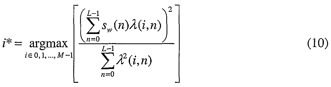
- the distortion metric is the perceptually weighted mean squared error between the z ' -th filtered adaptive codebook contribution ⁇ (i,ri), and the weighted target signal s w (n). This process is given in pitch delay adjust index search 218 and can be expressed as:
- i* is the optimal pitch delay adjust index corresponding to the maximum value obtained from the bracketed expression.
- a candidate pitch delay contour ⁇ c (n) is computed 210, and an adaptive codebook contribution E(n) is obtained 212 and filtered 220 to obtain the filtered adaptive codebook contribution ⁇ (n) as in the prior art.
- standard variables such as the fixed codebook indices, the FCB and ACB gain index, etc. are transmitted by transmitter 200.
- a delay adjust index (z) for each subframe is transmitted along with a code for the pitch delay value for the current frame ⁇ ri).
- the pitch delay from the previously transmitted frame ⁇ (m-l) is also used.
- the decoder will utilize i, ⁇ m), and ⁇ n-1) to produce an interpolation curve between successive pitch delay values.
- FIG. 3 is a block diagram of receiver 300.
- pitch delay parameter indexes are received by delay decoder 304 to produce ⁇ n).
- decoder 304 receives indices or "codes" representing ⁇ n), and decodes them to produce ⁇ (r ⁇ ) and ⁇ n- ⁇ ).
- Pitch delay values are output to pitch delay variability estimator 214 where the variation in pitch delay is determined and output to adaptive step size generator 215.
- a value for *(m) is computed by the generator 215.
- the adaptive step-size is output to delay adjust coefficient generator 216.
- a value for ⁇ ad] ( ⁇ ) is computed by generator216 as a function of the pitch delay adjust index i as discussed above, and output to endpoint modification circuitry 308.
- pitch delay ⁇ n) is output to delay interpolation block 307 and used to produce a subframe delay interpolation endpoint matrix d(m',j) according to equation 2.
- the shifted endpoints are then used by computation circuitry 310 to produce the adjusted delay contour ⁇ c (n), which is subsequently used to fetch samples from the ACB 312 (as in the prior art).
- the ACB contribution is then scaled and combined with the scaled fixed codebook contribution to produce a combined excitation signal, which is used as input to synthesis filter 302 to produce an output speech signal.
- the combined excitation signal is also used a feedback in order to update the ACB for the next subframe (as in the prior art).
- FIG. 4 shows a graphical representation of the signals of the previous section as displayed in the time domain. These signals are sampled based on a wideband speech coder configuration with a sampling frequency of 14 kHz. Therefore, signal 402 (the weighted speech signal s w (n)) comprises a one half second sample (7000 samples). For this example, the frame size is 280 samples, and the sub-frame size is 70. Signals 404-410 are displayed using one sample per sub-frame. From the input signal, the open-loop pitch delay ⁇ (n ⁇ ) 404 is estimated.
- the open-loop pitch delay ⁇ (n ⁇ ) 404 is estimated.
- the open-loop pitch delay estimate is fairly smooth for highly periodic speech (samples 0-2000 and 4000-6500), and in contrast is fairly erratic during non-voiced speech and transitions (samples 2000-4000 and 6500-7000).
- the step-size ftiri) 406 is shown. As can be seen, the step-size is relatively small when the variability of the pitch delay estimate is small, and conversely, the step-size is relatively large when the variability of the pitch delay estimate is large.
- the effects of the adaptive step-size can be seen further in the optimal pitch delay adjust value ⁇ adj (i) 408.
- the optimal pitch delay adjustment value is based on only four candidates (2 bits per sub-frame).
- the pitch delay adjusted endpoint d ⁇ m',l) 410 is shown to demonstrate the final composite estimate of the pitch delay contour in accordance with the present invention. When compared to the open-loop pitch delay 404, it is easy to see the overall effect of the invention.
- FIG. 5 is a flow chart showing operation of the encoder and decoder of FIG. 2 and FIG. 3, respectively.
- the logic flow begins at step 501 a pitch delay is estimated by delay estimation circuitry 204, or delay decoder 304 based on an input signal.
- the input signal is preferably speech, however other audio input signals are envisioned.
- pitch delay variability estimator 214 estimates the variation and /or standard deviation in pitch delay ( ⁇ ) based on the pitch delay estimate to produce an adaptive step- size value •(m).
- pitch delay adjust coefficient generator 216 uses • ⁇ m) and determines a value for an adjustment value (A, rf; )- As discussed above,
- a adj (i) (i - M / 2) - ⁇ (m), * e ⁇ 0, l, ..., M - l ⁇ , with
- the encoded pitch parameter comprise the endpoints of the pitch delay interpolation curve which are shifted up or down based on the adjustment value, and in particular according to the expression j) - d(m , j) + A adJ (i) , where i* is the optimal pitch delay adjust index corresponding to the maximum value obtained from equation 10.
- any encoded pitch parameter may be generated based on the adaptive step size.
- the present invention may be applied toward traditional closed loop pitch delay and pitch search methods (e.g., US Pat. No. 5,253,269) by allowing the search range and/or resolution (i.e., the step size) to be based on a function of the pitch delay variability. Such methods are currently limited to predetermined resolutions based solely on absolute range of the current pitch value being searched.
- any pitch delay parameter may be generated based on the adaptive step size.
- a speech decoder such as the GSM PIR may use an adaptive step size, based on the variation in pitch delay obtained from any first pitch delay parameter, to determine a range and resolution of the delta coded lag information (i.e., a second pitch delay parameter). Therefore, the second pitch delay parameter may be based on the adaptive step size.
- an alternate distortion metric may be used, such as the minimization of an accumulated shift parameter or the maximization of a normalized cross correlation parameter (as described in US Pat. No. 6,113,653) to achieve pitch delay contour adjustment in accordance with the present invention. It is obvious to one skilled in the art that the present invention is independent of the distortion metric being applied, and that any method may be used without departing from the spirit and scope of the present invention.
Landscapes
- Engineering & Computer Science (AREA)
- Multimedia (AREA)
- Computational Linguistics (AREA)
- Health & Medical Sciences (AREA)
- Audiology, Speech & Language Pathology (AREA)
- Human Computer Interaction (AREA)
- Physics & Mathematics (AREA)
- Signal Processing (AREA)
- Acoustics & Sound (AREA)
- Quality & Reliability (AREA)
- Data Mining & Analysis (AREA)
- Compression, Expansion, Code Conversion, And Decoders (AREA)
- Telephone Function (AREA)
- Transmission Systems Not Characterized By The Medium Used For Transmission (AREA)
- Compression Or Coding Systems Of Tv Signals (AREA)
- Picture Signal Circuits (AREA)
- Reduction Or Emphasis Of Bandwidth Of Signals (AREA)
Abstract
In a speech encoder/decoder (200/300) a pitch delay contour endpoint modifier (208) is employed to shift the endpoints of a pitch delay interpolation curve up or down. Particularly, the endpoints of the pitch delay interpolation curve are shifted based on a variation and/or a standard deviation in pitch delay.
Description
METHOD AND APPARATUS FOR CODING AN INFORMATION SIGNAL USING PITCH DELAY CONTOUR ADJUSTMENT
FIELD OF THE INVENTION
The present invention relates, in general, to communication systems and, more particularly, to coding information signals in such communication systems.
BACKGROUND OF THE INVENTION
Digital speech compression systems typically require estimation of the fundamental frequency of an input signal. The fundamental frequency / is usually estimated in terms of the pitch delay r (otherwise known as "lag"). The two are related by the expression

where the sampling frequency f is commonly 8000 Hz for telephone grade applications.
Since a speech signal is generally non-stationary, it is partitioned into finite length vectors called frames, each of which is presumed to be quasi- stationary. The length of such frames is normally on the order of 10 to 40 milliseconds. The parameters describing the speech signal are then updated at the associated frame length intervals. The original Code Excited Linear Prediction (CELP) algorithms further updates the pitch period (using what is called Long Term Prediction, or LTP) information on shorter sub-frame intervals, thus allowing smoother transitions from frame to frame. It was also noted that although τ could be estimated using open-loop methods, far better performance was achieved using the closed-loop approach. Closed-loop
methods involve a trial-and-error search of different possible values of r (typically integer values from 20 to 147) on a sub-frame basis, and choosing the value that satisfies some minimum error criterion.
An enhancement to this method involves allowing τ to take on integer plus fractional values, as given in US Pat. No. US 5,359,696. An example of a practical implementation of this method can be found in the GSM half rate speech coder, and is shown in FIG. 1 and described in US Pat. No. US 5,253,269. Here, lags within the range of 21 to 22-2/3 are allowed 1/3 sample resolution, lags within the range of 23 to 34-5/6 are allowed 1/6 sample resolution, and so on. In order to keep the search complexity low, a combination of open-loop and closed loop methods is used. The open-loop method involves generating an integer lag candidate list using an autocorrelation peak picking algorithm. The closed-loop method then searches the allowable lags in the neighborhood of the integer lag candidates for the optimal fractional lag value. Furthermore, the lags for sub-frames 2, 3, and 4 are coded based on the difference from the previous sub-frame. This allows the lag information to be coded using fewer bits since there is a high intra-frame correlation of the lag parameter. Even so, the GSM HR codec uses a total of 8 + (3 x 4) = 20 bits every 20 ms (1.0 kbps) to convey the pitch period information.
In an effort to reduce the bit rate of the pitch period information, an interpolation strategy was developed that allows the pitch information to be coded only once per frame (using only 7 bits => 350 bps), rather than with the usual sub-frame resolution. This technique is known as relaxed CELP (or RCELP), and is the basis for the Enhanced Variable Rate Codec (EVRC) standard for Code Division Multiple Access (CDMA) wireless telephone systems. The basic principle is as follows.
The pitch period is estimated for the analysis window centered at the end of the current frame. The lag (pitch delay) contour is then generated, which consists of a linear interpolation of the past frame's lag to the current
frame's lag. The linear prediction (LP) residual signal is then modified by means of sophisticated polyphase filtering and shifting techniques/ which is designed to match the residual waveform to the estimated pitch delay contour. The primary reason for this residual modification process is to account for accuracy limitations of the open-loop integer lag estimation process. For example, if the integer lag is estimated to be 32 samples, when in fact the true lag is 32.5 samples, the residual waveform can be in conflict with the estimated lag by as many as 2.5 samples in a single 160 sample frame. This can severely degrade the performance of the LTP. The RCELP algorithm accounts for this by shifting the residual waveform during perceptually insignificant instances in the residual waveform (i.e., low energy) to match the estimated pitch delay contour. By modifying the residual waveform to match the estimated pitch delay contour, the effectiveness of the LTP is preserved, and the coding gain is maintained. In addition, the associated perceptual degradations due to the residual modification are claimed to be insignificant.
A further improvement to processing of the pitch delay contour information has been proposed in US Pat. No. 6,113,653, in which a method of adjusting the pitch delay contour at intervals of less than of equal to one block in length is disclosed. In this method, a small number of bits are used to code an adjustment of the pitch delay contour according to some error minimization criteria. The method describes techniques for pitch delay contour adjustment by minimization of an accumulated shift parameter, or maximization of the cross correlation between the perceptually weighted input speech and the adaptive codebook (ACB) contribution passed through a perceptually weighted synthesis filter. Another well known pitch delay adjustment criterion may also include the minimization of the perceptually weighted error energy between the target speech and the filtered ACB contribution.
While this method utilizes a very efficient technique for estimating and coding pitch delay contour adjustment information, the low bit rate has the
consequence of constraining the resolution and/or dynamic range of the pitch delay adjustment parameters being coded. Therefore a need exists for improving performance of low bit rate long-term predictors by adaptively modifying the dynamic range and resolution of the predictor step-size, such that higher long-term prediction gain is achieved for a given bit-rate, or alternatively, a similar long-term prediction is achieved at a lower bit-rate when compared to the prior art.
BRIEF DESCRIPTION OF THE DRAWINGS
FIG. 1 is a block diagram of a prior-art speech encoder.
FIG. 2 is a block diagram of a speech encoder.
FIG. 3 is a block diagram of a speech decoder.
FIG. 4 illustrates a graphical representation of signals as displayed in the time domain.
FIG. 5 is a flow chart showing operation of the encoder and decoder of FIG. 2 and FIG. 3.
DETAILED DESCRIPTION OF THE PREFERRED EMBODIMENT
Stated generally, an open-loop pitch delay contour estimator generates pitch delay information during coding of an information signal. The pitch delay contour (i.e., a linear interpolation of the past frame's lag to the current frame's lag) is adjusted on a sub-frame basis which allows a more precise estimate of the true pitch delay contour. A pitch delay contour reconstruction block uses the pitch delay information in a decoder in reconstructing the information signal between frames. In the preferred embodiment of the present invention adjustment of the pitch delay contour is based on a standard deviation and/or a variance in pitch delay (r).
Stated more specifically, a method for coding an information signal comprises the steps of dividing the information signal into blocks, estimating the pitch delay of the current and previous blocks of information and forming an adjustment in pitch delay based on a past changes (e.g., standard deviation and/or variance) in τ. The method further includes the steps of adjusting the shape of the pitch delay contour at intervals of less than or equal to one block in length and coding the shape of the adjusted pitch delay contour to produce codes suitable for transmission to a destination.
The step of adjusting the shape of the pitch delay contour at intervals of less than or equal to one block in length further comprises the steps of determining the adjusted pitch delay at a point at or between the current and previous pitch delays and forming a linear interpolation between the previous pitch delay point and the adjusted pitch delay point. When determining the adjusted pitch delay point, a change in accumulated shift is minimized. The step of determining the adjusted pitch delay further comprises the step of maximizing the correlation between a target residual signal and the original residual signal. The previous pitch delay point further comprises a previously adjusted pitch delay point. Alternatively, the step of adjusting the shape of the pitch delay contour further comprises the steps of determining a plurality of adjusted pitch delay points at or between the current and previous pitch delays and forming a linear interpolation between the adjusted pitch delay points.
A system for coding an information signal is also disclosed. The system includes an coder which comprises means for dividing the information signal into blocks and means for estimating the pitch delay of the current and previous blocks of information and for adjusting a pitch delay based on a past changes (e.g., standard deviation and/or variance) in τ.
Within the system, the information signal further comprises either a speech or an audio signal and the blocks of information signals further comprise frames of information signals. The pitch delay information further
conaprises a pitch delay adjustment index. The system also includes a decoder for receiving the pitch delay information and for producing an adjusted pitch delay contour τc(n) for use in reconstructing the information signal.
FIG. 2 generally depicts a speech compression system 200 employing adaptive step-size pitch delay adjustment in accordance with the preferred embodiment of the present invention. As shown in FIG. 2, the input speech signal s(n) is processed by a linear prediction (LP) analysis filter 202 which flattens the short-term spectral envelope of input speech signal s(n). The output of the LP analysis filter is designated as the LP residual ε(n). The LP residual signal ε(n) is then used by the open-loop pitch delay estimator 204 to generate the open-loop pitch delay φn). (Details of this and some other processes in the following discussion are given in TIA-127 EVRC.) The open- loop pitch delay τ(m) is then used by pitch delay interpolation block 206 to produce a subframe delay interpolation endpoint matrix d(m',j) according to the expression:

l ≤ ro' < 3
where φn) is the estimated open-loop pitch delay for the current frame m, which is centered at the end current frame, i(m~l) is the estimated open-loop pitch delay for the previous frame m-1, and f(n) is a set of pitch delay interpolation coefficients, which may be defined as:
f = { 0.0, 0.3313, 0.6625, 1.0 } (3)
These coefficients are given for the example of when the number of sub- frames is three (e.g, 0< m'<3), although a suitable set of coefficients can be derived for a value of sub-frames other than three.
Also using the open-loop pitch delay τ{m) as input is the pitch delay variability estimator 214. In accordance with the current invention, the sample standard deviation of the open-loop pitch delay estimate is defined as:

τ =±∑φι-i) (5)
N ,=o
When the number of observations is two (N=2), it can be shown that the above expressions can be simplified to the following:

The variability estimate στ and the open-loop pitch delay φn) are then used as inputs to the adaptive step size generator 215, where the adaptive step size δ(m) is calculated as a function of <7ras:
δ{m) = a(στ ) 1 , (7)
where a(σT) is some function of the variability estimate of pitch delay. For the preferred embodiment of the present invention, this function is given as:
a(σr) = min{Aστ + B, aimx ) (8)
where A and B may be constants, στ represents the standard deviation in % and <jmax may be some maximum allowable value of «(στ).
The adaptive step-size <5(m) is input to the delay adjust coefficient generator 216, where the pitch delay adjust value ΔΛrf/(i) may be calculated as a function of the pitch delay adjust index i as:
Δflrf,(O = (ϊ - M /2) - £(m), ie {0, l, ..., M -l} (9)
where M is the number of candidate pitch delay adjustment indices. From the equations above, it can be seen that the pitch delay adjust value Δadfi) may take on integral multiples of the step-size δ[m), where δ(m) is a function of not only the average (mean) value of the pitch delay (as in the prior at), but also the variability estimate σr of the pitch delay value φri). The various pitch delay adjust values may then be evaluated according to some distortion metric, and as a result, the optimal value of the pitch delay adjust value may be used throughout the remainder of the coding process. In the preferred embodiment, the distortion metric is the perceptually weighted mean squared error between the z'-th filtered adaptive codebook contribution λ(i,ri), and the weighted target signal sw(n). This process is given in pitch delay adjust index search 218 and can be expressed as:
In order to obtain the signals used in Eq. 10, the pitch delay contour endpoint modifier 208 is employed to shift the endpoints of the pitch delay interpolation curve up or down according to the expression:
d'(m', j) = d(m',j) + AadJ (i) (11)
From this expression, a candidate pitch delay contour τc(n) is computed 210, and an adaptive codebook contribution E(n) is obtained 212 and filtered 220 to obtain the filtered adaptive codebook contribution λ(n) as in the prior art. During operation standard variables such as the fixed codebook indices, the FCB and ACB gain index, etc. are transmitted by transmitter 200. Along with these values, a delay adjust index (z) for each subframe is transmitted along with a code for the pitch delay value for the current frame φri). The pitch delay from the previously transmitted frame τ(m-l) is also used. The decoder will utilize i, τ{m), and φn-1) to produce an interpolation curve between successive pitch delay values. More particularly, the receiver will compute ΔΛd H) as a function of the pitch delay adjust index i as discussed above, and apply ΔΛd;(i) to shift the endpoints of the pitch delay interpolation curve up or down according to equation 11. FIG. 3 is a block diagram of receiver 300. As shown, pitch delay parameter indexes are received by delay decoder 304 to produce φn). More particularly, decoder 304 receives indices or "codes" representing φn), and decodes them to produceτ(rø) and φn-ϊ). Pitch delay values are output to pitch delay variability estimator 214 where the variation in pitch delay is determined and output to adaptive step size generator 215. A value for *(m) is computed by the generator 215. The adaptive step-size is output to delay adjust coefficient generator 216. A value for Δad](ϊ) is computed by generator216 as a function of the pitch delay adjust index i as discussed above, and output to endpoint modification circuitry 308. As with transmitter 200, pitch delay φn) is output to delay interpolation block 307 and used to produce a subframe delay interpolation endpoint matrix d(m',j) according to equation 2. Delay contour endpoint modification circuitry 308 takes the endpoint matrix and shifts the endpoints of the pitch delay interpolation curve up or down according to
d'(m , j) = d(m',j) + Aaιlj(i) . The shifted endpoints are then used by computation circuitry 310 to produce the adjusted delay contour τc(n), which is subsequently used to fetch samples from the ACB 312 (as in the prior art). The ACB contribution is then scaled and combined with the scaled fixed codebook contribution to produce a combined excitation signal, which is used as input to synthesis filter 302 to produce an output speech signal. The combined excitation signal is also used a feedback in order to update the ACB for the next subframe (as in the prior art).
FIG. 4 shows a graphical representation of the signals of the previous section as displayed in the time domain. These signals are sampled based on a wideband speech coder configuration with a sampling frequency of 14 kHz. Therefore, signal 402 (the weighted speech signal sw(n)) comprises a one half second sample (7000 samples). For this example, the frame size is 280 samples, and the sub-frame size is 70. Signals 404-410 are displayed using one sample per sub-frame. From the input signal, the open-loop pitch delay τ(nϊ) 404 is estimated.
As can be seen, the open-loop pitch delay estimate is fairly smooth for highly periodic speech (samples 0-2000 and 4000-6500), and in contrast is fairly erratic during non-voiced speech and transitions (samples 2000-4000 and 6500-7000). In accordance with the present invention, the step-size ftiri) 406 is shown. As can be seen, the step-size is relatively small when the variability of the pitch delay estimate is small, and conversely, the step-size is relatively large when the variability of the pitch delay estimate is large. The effects of the adaptive step-size can be seen further in the optimal pitch delay adjust value Δadj(i) 408. Here, the optimal pitch delay adjustment value is based on only four candidates (2 bits per sub-frame). During the highly periodic regions, the variation is small and resolution is emphasized to allow fine tuning of the pitch delay estimate. During non-voiced and transition regions, pitch delay variation is large and subsequently a wide dynamic range is emphasized to account for a high uncertainty in the pitch delay estimate. Finally, the pitch delay adjusted endpoint d\m',l) 410 is shown to
demonstrate the final composite estimate of the pitch delay contour in accordance with the present invention. When compared to the open-loop pitch delay 404, it is easy to see the overall effect of the invention.
FIG. 5 is a flow chart showing operation of the encoder and decoder of FIG. 2 and FIG. 3, respectively. In particular, the generation of the pitch delay adjustment value ΔJrf/ by encoder 200 and decoder 300 is described. The logic flow begins at step 501 a pitch delay is estimated by delay estimation circuitry 204, or delay decoder 304 based on an input signal. In the preferred embodiment of the present invention the input signal is preferably speech, however other audio input signals are envisioned. At step 503 pitch delay variability estimator 214 estimates the variation and /or standard deviation in pitch delay (τ) based on the pitch delay estimate to produce an adaptive step- size value •(m). More particularly, past values of rare analyzed to determine στ, *(m) is computed from στ per equation (7). . At step 505 pitch delay adjust coefficient generator 216 uses •{m) and determines a value for an adjustment value (A,rf;)- As discussed above,
Aadj (i) = (i - M / 2) - δ(m), * e {0, l, ..., M - l}, with
o sv(m . - TP1he va ilue f j-or Δ 4 nrf;i ■s t Lihen used J i by mod Ji-fJTi-cat Li-on
 circuitry 208 to generate a second pitch delay parameter, an in particular an encoded pitch parameter (step 507). In the preferred embodiment of the present invention the encoded pitch parameter comprise the endpoints of the pitch delay interpolation curve which are shifted up or down based on the adjustment value, and in particular according to the expression j) - d(m , j) + AadJ(i) , where i* is the optimal pitch delay adjust index corresponding to the maximum value obtained from equation 10.
While the invention has been particularly shown and described with reference to a particular embodiment, it will be understood by those skilled in the art that various changes in form and details may be made therein without departing from the spirit and scope of the invention. For example, while in
the preferred embodiment of the present invention endpoints of a pitch delay- interpolation curve are shifted based on the adaptive step size, one of ordinary skill in the art will recognize that any encoded pitch parameter may be generated based on the adaptive step size. More specifically, the present invention may be applied toward traditional closed loop pitch delay and pitch search methods (e.g., US Pat. No. 5,253,269) by allowing the search range and/or resolution (i.e., the step size) to be based on a function of the pitch delay variability. Such methods are currently limited to predetermined resolutions based solely on absolute range of the current pitch value being searched.
Use of the present invention in prior art decoding processes is also viewed to be obvious by one skilled in the art. For example, while in the preferred embodiment of the present invention endpoints of a pitch delay interpolation curve are shifted up or down based on the adaptive step size, one of ordinary skill in the art will recognize that any pitch delay parameter may be generated based on the adaptive step size. As in the previous discussion, a speech decoder such as the GSM PIR may use an adaptive step size, based on the variation in pitch delay obtained from any first pitch delay parameter, to determine a range and resolution of the delta coded lag information (i.e., a second pitch delay parameter). Therefore, the second pitch delay parameter may be based on the adaptive step size.
In addition, an alternate distortion metric may be used, such as the minimization of an accumulated shift parameter or the maximization of a normalized cross correlation parameter (as described in US Pat. No. 6,113,653) to achieve pitch delay contour adjustment in accordance with the present invention. It is obvious to one skilled in the art that the present invention is independent of the distortion metric being applied, and that any method may be used without departing from the spirit and scope of the present invention.
What we claim is:
Claims
1. A method of operating a speech encoder, the method comprising the steps of: estimating a pitch delay based on an input signal; estimating a variation in pitch delay based on the pitch delay estimate; determining an adaptive step size value based on the variation in pitch delay; and generating an encoded pitch parameter based on the adaptive step size.
2. The method of claim 1 wherein the step of estimating the pitch delay based on the input signal comprises the step of estimating the pitch delay based on either a speech or an audio signal.
3. The method of claim 1 wherein the step of estimating the variation in pitch delay comprises the step of estimating a variation and /or standard deviation in pitch delay.
4. The method of claim 1 wherein the step of determining the adaptive step size comprises the step of determining the adaptive step size dim), where δ(nι) may be expressed as:
δ(m) = a(στ )l κ '-
and where α(σv) is some function of the variability estimate of pitch delay, and φ?z) is a pitch delay estimate for frame number m.
5. The method of claim 4 wherein a(στ) = min(Aσr + B, amax )where A and B are predetermined values, στ represents the standard deviation in τ, and αmax is a maximum allowable value of o(σ^).
6. The method of claim 1 wherein the step of generating an encoded pitch parameter based on the adaptive step size comprises the step of determining a delay adjust value Δaιij where
AadJ(i) = (i - M /2) - δ(m\ /e {0, l, ..., M -l} and where M is the number of candidate pitch delay adjustment indices, δ{rn) is the adaptive step-size, and ie {θ, 1, ..., M -l} is the encoded pitch parameter.
7. The method of claim 6 wherein the delay adjust value AadJ is used to shift the endpoints of the pitch delay interpolation curve up or down according to the expression: d'(m , j) = d(m'j) + \dJ(i) where d(m , j) is a subframe delay interpolation endpoint matrix.
8. The method of claim 1 wherein the step of generating an encoded pitch parameter based on the adaptive step size comprises the step of evaluating a distortion criteria.
9. The method of claim 8 wherein the step of evaluating the distortion criteria comprises the step of evaluating one of the set of the minimization of a mean squared error parameter, the minimization of an accumulated shift parameter, and the maximization of a normalized cross correlation parameter.
10. A method of operating a speech decoder, the method comprising the steps of: receiving a first pitch delay parameter; estimating a variation in pitch delay based on the first pitch delay parameter; determining an adaptive step size based on the variation in pitch delay; and generating a second pitch delay parameter based on the adaptive step size.
11. The method of claim 10 wherein the step of estimating the variation in pitch delay comprises the step of estimating a variation and /or standard deviation in pitch delay.
12. The method of claim 10 wherein the step of determining the adaptive step size comprises the step of determining the adaptive step size δ(m), where δ(m) may be expressed as:
S(m) = a{στ ) ?
where o{σ^ is some function of the variability estimate of pitch delay, and ■ύitn) is a pitch delay estimate for frame number m.
13. The method of claim 12 wherein a(σT) = min(Aστ + B, a^ ) where A and B are predetermined, στ represents the standard deviation in τ, and am∞. is a maximum allowable value of a(σ^.
14. The method of claim 10 wherein the step of generating the second pitch delay parameter based on the adaptive step size comprises the step of determining a delay adjust value Δnii; where
Δβ&(i) = (i -M /2) - 5(m), i s {θ, l, ..., M -l} and where M is the number of candidate pitch delay adjustment indices, and δ(m) is the adaptive step-size.
15. The method of claim 14 wherein the delay adjust value Aa(lj is used to shift the endpoints of the pitch delay interpolation curve up or down according to the expression: d'(m'J) = d(m'J) + Aadj(i) where d{m , j) is a subframe delay interpolation endpoint matrix, and d\m , f) is the second pitch delay parameter.
16. An apparatus comprising: a variability estimator estimating a variation in pitch delay; a coefficient generator determining an adaptive step size based on the variation in pitch delay; and modification circuitry modifying a pitch parameter based on the adaptive step size.
17. The apparatus of claim 16 wherein the modification circuitry modifies endpoints of a pitch delay interpolation curve up or down based on the adaptive step size.
18. The apparatus of claim 16 wherein the pitch delay is based either a speech or an audio signal.
19. The apparatus of claim 16 wherein the variation in pitch delay comprises a variation and /or standard deviation in pitch delay.
20. The apparatus of claim 16 wherein the adaptive step size is computed as
δ(m) = a(στ)\ ^ }- \
and α(στ) is some function of the variability estimate of pitch delay.
Priority Applications (5)
| Application Number | Priority Date | Filing Date | Title |
|---|---|---|---|
| JP2008523898A JP4611424B2 (en) | 2005-07-27 | 2006-06-29 | Method and apparatus for encoding an information signal using pitch delay curve adjustment |
| DE602006012061T DE602006012061D1 (en) | 2005-07-27 | 2006-06-29 | METHOD AND DEVICE FOR CODING AN INFORMATION SIGNAL USING A SOUND DELAY CONTOUR SETTING |
| EP06785795A EP1922718B1 (en) | 2005-07-27 | 2006-06-29 | Method and apparatus for coding an information signal using pitch delay contour adjustment |
| CN2006800272071A CN101228573B (en) | 2005-07-27 | 2006-06-29 | Method and apparatus for coding an information signal using pitch delay contour adjustment |
| AT06785795T ATE456846T1 (en) | 2005-07-27 | 2006-06-29 | METHOD AND APPARATUS FOR ENCODING AN INFORMATION SIGNAL USING A PITCH DELAY CONTOUR ADJUSTMENT |
Applications Claiming Priority (2)
| Application Number | Priority Date | Filing Date | Title |
|---|---|---|---|
| US11/190,680 | 2005-07-27 | ||
| US11/190,680 US9058812B2 (en) | 2005-07-27 | 2005-07-27 | Method and system for coding an information signal using pitch delay contour adjustment |
Publications (2)
| Publication Number | Publication Date |
|---|---|
| WO2007018815A2 true WO2007018815A2 (en) | 2007-02-15 |
| WO2007018815A3 WO2007018815A3 (en) | 2007-10-04 |
Family
ID=37695451
Family Applications (1)
| Application Number | Title | Priority Date | Filing Date |
|---|---|---|---|
| PCT/US2006/025273 Ceased WO2007018815A2 (en) | 2005-07-27 | 2006-06-29 | Method and apparatus for coding an information signal using pitch delay contour adjustment |
Country Status (8)
| Country | Link |
|---|---|
| US (1) | US9058812B2 (en) |
| EP (1) | EP1922718B1 (en) |
| JP (1) | JP4611424B2 (en) |
| KR (1) | KR100979090B1 (en) |
| CN (1) | CN101228573B (en) |
| AT (1) | ATE456846T1 (en) |
| DE (1) | DE602006012061D1 (en) |
| WO (1) | WO2007018815A2 (en) |
Cited By (1)
| Publication number | Priority date | Publication date | Assignee | Title |
|---|---|---|---|---|
| US8886548B2 (en) | 2009-10-21 | 2014-11-11 | Panasonic Corporation | Audio encoding device, decoding device, method, circuit, and program |
Families Citing this family (81)
| Publication number | Priority date | Publication date | Assignee | Title |
|---|---|---|---|---|
| US9058812B2 (en) * | 2005-07-27 | 2015-06-16 | Google Technology Holdings LLC | Method and system for coding an information signal using pitch delay contour adjustment |
| US9339278B2 (en) | 2006-02-27 | 2016-05-17 | Biomet Manufacturing, Llc | Patient-specific acetabular guides and associated instruments |
| US8070752B2 (en) | 2006-02-27 | 2011-12-06 | Biomet Manufacturing Corp. | Patient specific alignment guide and inter-operative adjustment |
| US9345548B2 (en) * | 2006-02-27 | 2016-05-24 | Biomet Manufacturing, Llc | Patient-specific pre-operative planning |
| US8241293B2 (en) * | 2006-02-27 | 2012-08-14 | Biomet Manufacturing Corp. | Patient specific high tibia osteotomy |
| US8298237B2 (en) * | 2006-06-09 | 2012-10-30 | Biomet Manufacturing Corp. | Patient-specific alignment guide for multiple incisions |
| US9173661B2 (en) | 2006-02-27 | 2015-11-03 | Biomet Manufacturing, Llc | Patient specific alignment guide with cutting surface and laser indicator |
| US8608748B2 (en) * | 2006-02-27 | 2013-12-17 | Biomet Manufacturing, Llc | Patient specific guides |
| US9918740B2 (en) | 2006-02-27 | 2018-03-20 | Biomet Manufacturing, Llc | Backup surgical instrument system and method |
| US8282646B2 (en) | 2006-02-27 | 2012-10-09 | Biomet Manufacturing Corp. | Patient specific knee alignment guide and associated method |
| US8092465B2 (en) * | 2006-06-09 | 2012-01-10 | Biomet Manufacturing Corp. | Patient specific knee alignment guide and associated method |
| US7967868B2 (en) | 2007-04-17 | 2011-06-28 | Biomet Manufacturing Corp. | Patient-modified implant and associated method |
| US8407067B2 (en) | 2007-04-17 | 2013-03-26 | Biomet Manufacturing Corp. | Method and apparatus for manufacturing an implant |
| US20150335438A1 (en) | 2006-02-27 | 2015-11-26 | Biomet Manufacturing, Llc. | Patient-specific augments |
| US8133234B2 (en) * | 2006-02-27 | 2012-03-13 | Biomet Manufacturing Corp. | Patient specific acetabular guide and method |
| US8377066B2 (en) * | 2006-02-27 | 2013-02-19 | Biomet Manufacturing Corp. | Patient-specific elbow guides and associated methods |
| US8864769B2 (en) * | 2006-02-27 | 2014-10-21 | Biomet Manufacturing, Llc | Alignment guides with patient-specific anchoring elements |
| US9907659B2 (en) | 2007-04-17 | 2018-03-06 | Biomet Manufacturing, Llc | Method and apparatus for manufacturing an implant |
| US8473305B2 (en) | 2007-04-17 | 2013-06-25 | Biomet Manufacturing Corp. | Method and apparatus for manufacturing an implant |
| US10278711B2 (en) * | 2006-02-27 | 2019-05-07 | Biomet Manufacturing, Llc | Patient-specific femoral guide |
| US8858561B2 (en) * | 2006-06-09 | 2014-10-14 | Blomet Manufacturing, LLC | Patient-specific alignment guide |
| US8603180B2 (en) | 2006-02-27 | 2013-12-10 | Biomet Manufacturing, Llc | Patient-specific acetabular alignment guides |
| US8591516B2 (en) | 2006-02-27 | 2013-11-26 | Biomet Manufacturing, Llc | Patient-specific orthopedic instruments |
| US8608749B2 (en) | 2006-02-27 | 2013-12-17 | Biomet Manufacturing, Llc | Patient-specific acetabular guides and associated instruments |
| US9113971B2 (en) | 2006-02-27 | 2015-08-25 | Biomet Manufacturing, Llc | Femoral acetabular impingement guide |
| US20110190899A1 (en) * | 2006-02-27 | 2011-08-04 | Biomet Manufacturing Corp. | Patient-specific augments |
| US9289253B2 (en) | 2006-02-27 | 2016-03-22 | Biomet Manufacturing, Llc | Patient-specific shoulder guide |
| US8568487B2 (en) | 2006-02-27 | 2013-10-29 | Biomet Manufacturing, Llc | Patient-specific hip joint devices |
| US8535387B2 (en) | 2006-02-27 | 2013-09-17 | Biomet Manufacturing, Llc | Patient-specific tools and implants |
| US9795399B2 (en) | 2006-06-09 | 2017-10-24 | Biomet Manufacturing, Llc | Patient-specific knee alignment guide and associated method |
| US8346546B2 (en) * | 2006-08-15 | 2013-01-01 | Broadcom Corporation | Packet loss concealment based on forced waveform alignment after packet loss |
| US8265949B2 (en) | 2007-09-27 | 2012-09-11 | Depuy Products, Inc. | Customized patient surgical plan |
| US8425524B2 (en) | 2007-09-30 | 2013-04-23 | DePuy Synthes Products, LLC | Customized patient-specific multi-cutting blocks |
| US8357111B2 (en) | 2007-09-30 | 2013-01-22 | Depuy Products, Inc. | Method and system for designing patient-specific orthopaedic surgical instruments |
| US8170641B2 (en) | 2009-02-20 | 2012-05-01 | Biomet Manufacturing Corp. | Method of imaging an extremity of a patient |
| DE102009028503B4 (en) | 2009-08-13 | 2013-11-14 | Biomet Manufacturing Corp. | Resection template for the resection of bones, method for producing such a resection template and operation set for performing knee joint surgery |
| US8632547B2 (en) | 2010-02-26 | 2014-01-21 | Biomet Sports Medicine, Llc | Patient-specific osteotomy devices and methods |
| US9066727B2 (en) | 2010-03-04 | 2015-06-30 | Materialise Nv | Patient-specific computed tomography guides |
| US9271744B2 (en) | 2010-09-29 | 2016-03-01 | Biomet Manufacturing, Llc | Patient-specific guide for partial acetabular socket replacement |
| US9968376B2 (en) | 2010-11-29 | 2018-05-15 | Biomet Manufacturing, Llc | Patient-specific orthopedic instruments |
| US9241745B2 (en) | 2011-03-07 | 2016-01-26 | Biomet Manufacturing, Llc | Patient-specific femoral version guide |
| US8715289B2 (en) | 2011-04-15 | 2014-05-06 | Biomet Manufacturing, Llc | Patient-specific numerically controlled instrument |
| US9675400B2 (en) | 2011-04-19 | 2017-06-13 | Biomet Manufacturing, Llc | Patient-specific fracture fixation instrumentation and method |
| US8956364B2 (en) | 2011-04-29 | 2015-02-17 | Biomet Manufacturing, Llc | Patient-specific partial knee guides and other instruments |
| US8668700B2 (en) | 2011-04-29 | 2014-03-11 | Biomet Manufacturing, Llc | Patient-specific convertible guides |
| US8532807B2 (en) | 2011-06-06 | 2013-09-10 | Biomet Manufacturing, Llc | Pre-operative planning and manufacturing method for orthopedic procedure |
| US9084618B2 (en) | 2011-06-13 | 2015-07-21 | Biomet Manufacturing, Llc | Drill guides for confirming alignment of patient-specific alignment guides |
| US8764760B2 (en) | 2011-07-01 | 2014-07-01 | Biomet Manufacturing, Llc | Patient-specific bone-cutting guidance instruments and methods |
| US20130001121A1 (en) | 2011-07-01 | 2013-01-03 | Biomet Manufacturing Corp. | Backup kit for a patient-specific arthroplasty kit assembly |
| US8597365B2 (en) | 2011-08-04 | 2013-12-03 | Biomet Manufacturing, Llc | Patient-specific pelvic implants for acetabular reconstruction |
| US9295497B2 (en) | 2011-08-31 | 2016-03-29 | Biomet Manufacturing, Llc | Patient-specific sacroiliac and pedicle guides |
| US9066734B2 (en) | 2011-08-31 | 2015-06-30 | Biomet Manufacturing, Llc | Patient-specific sacroiliac guides and associated methods |
| US9386993B2 (en) | 2011-09-29 | 2016-07-12 | Biomet Manufacturing, Llc | Patient-specific femoroacetabular impingement instruments and methods |
| KR20130046336A (en) | 2011-10-27 | 2013-05-07 | 삼성전자주식회사 | Multi-view device of display apparatus and contol method thereof, and display system |
| US9554910B2 (en) | 2011-10-27 | 2017-01-31 | Biomet Manufacturing, Llc | Patient-specific glenoid guide and implants |
| US9301812B2 (en) | 2011-10-27 | 2016-04-05 | Biomet Manufacturing, Llc | Methods for patient-specific shoulder arthroplasty |
| US9451973B2 (en) | 2011-10-27 | 2016-09-27 | Biomet Manufacturing, Llc | Patient specific glenoid guide |
| WO2013062848A1 (en) | 2011-10-27 | 2013-05-02 | Biomet Manufacturing Corporation | Patient-specific glenoid guides |
| US9274683B2 (en) * | 2011-12-30 | 2016-03-01 | Google Inc. | Interactive answer boxes for user search queries |
| US9237950B2 (en) | 2012-02-02 | 2016-01-19 | Biomet Manufacturing, Llc | Implant with patient-specific porous structure |
| CA3210225A1 (en) * | 2012-11-15 | 2014-05-22 | Ntt Docomo, Inc. | Audio coding device, audio coding method, audio coding program, audio decoding device, audio decoding method, and audio decoding program |
| US9060788B2 (en) | 2012-12-11 | 2015-06-23 | Biomet Manufacturing, Llc | Patient-specific acetabular guide for anterior approach |
| US9204977B2 (en) | 2012-12-11 | 2015-12-08 | Biomet Manufacturing, Llc | Patient-specific acetabular guide for anterior approach |
| US9839438B2 (en) | 2013-03-11 | 2017-12-12 | Biomet Manufacturing, Llc | Patient-specific glenoid guide with a reusable guide holder |
| US9579107B2 (en) | 2013-03-12 | 2017-02-28 | Biomet Manufacturing, Llc | Multi-point fit for patient specific guide |
| US9498233B2 (en) | 2013-03-13 | 2016-11-22 | Biomet Manufacturing, Llc. | Universal acetabular guide and associated hardware |
| US9826981B2 (en) | 2013-03-13 | 2017-11-28 | Biomet Manufacturing, Llc | Tangential fit of patient-specific guides |
| US9517145B2 (en) | 2013-03-15 | 2016-12-13 | Biomet Manufacturing, Llc | Guide alignment system and method |
| US20150112349A1 (en) | 2013-10-21 | 2015-04-23 | Biomet Manufacturing, Llc | Ligament Guide Registration |
| US10282488B2 (en) | 2014-04-25 | 2019-05-07 | Biomet Manufacturing, Llc | HTO guide with optional guided ACL/PCL tunnels |
| US9408616B2 (en) | 2014-05-12 | 2016-08-09 | Biomet Manufacturing, Llc | Humeral cut guide |
| US9839436B2 (en) | 2014-06-03 | 2017-12-12 | Biomet Manufacturing, Llc | Patient-specific glenoid depth control |
| US9561040B2 (en) | 2014-06-03 | 2017-02-07 | Biomet Manufacturing, Llc | Patient-specific glenoid depth control |
| US9826994B2 (en) | 2014-09-29 | 2017-11-28 | Biomet Manufacturing, Llc | Adjustable glenoid pin insertion guide |
| US9833245B2 (en) | 2014-09-29 | 2017-12-05 | Biomet Sports Medicine, Llc | Tibial tubercule osteotomy |
| US9820868B2 (en) | 2015-03-30 | 2017-11-21 | Biomet Manufacturing, Llc | Method and apparatus for a pin apparatus |
| US10568647B2 (en) | 2015-06-25 | 2020-02-25 | Biomet Manufacturing, Llc | Patient-specific humeral guide designs |
| US10226262B2 (en) | 2015-06-25 | 2019-03-12 | Biomet Manufacturing, Llc | Patient-specific humeral guide designs |
| US10722310B2 (en) | 2017-03-13 | 2020-07-28 | Zimmer Biomet CMF and Thoracic, LLC | Virtual surgery planning system and method |
| US11051829B2 (en) | 2018-06-26 | 2021-07-06 | DePuy Synthes Products, Inc. | Customized patient-specific orthopaedic surgical instrument |
| CN113870885B (en) * | 2021-12-02 | 2022-02-22 | 北京百瑞互联技术有限公司 | Bluetooth audio squeal detection and suppression method, device, medium, and apparatus |
Family Cites Families (43)
| Publication number | Priority date | Publication date | Assignee | Title |
|---|---|---|---|---|
| US4201958A (en) * | 1977-12-27 | 1980-05-06 | Bell Telephone Laboratories, Incorporated | Delta modulation which partitions input signal into variable-time segments that are iteratively encoded |
| CA1252568A (en) * | 1984-12-24 | 1989-04-11 | Kazunori Ozawa | Low bit-rate pattern encoding and decoding capable of reducing an information transmission rate |
| JP2884163B2 (en) * | 1987-02-20 | 1999-04-19 | 富士通株式会社 | Coded transmission device |
| US5359696A (en) | 1988-06-28 | 1994-10-25 | Motorola Inc. | Digital speech coder having improved sub-sample resolution long-term predictor |
| US5097508A (en) | 1989-08-31 | 1992-03-17 | Codex Corporation | Digital speech coder having improved long term lag parameter determination |
| US5253269A (en) | 1991-09-05 | 1993-10-12 | Motorola, Inc. | Delta-coded lag information for use in a speech coder |
| SE469764B (en) * | 1992-01-27 | 1993-09-06 | Ericsson Telefon Ab L M | SET TO CODE A COMPLETE SPEED SIGNAL VECTOR |
| US5495555A (en) * | 1992-06-01 | 1996-02-27 | Hughes Aircraft Company | High quality low bit rate celp-based speech codec |
| CA2154911C (en) * | 1994-08-02 | 2001-01-02 | Kazunori Ozawa | Speech coding device |
| JP3087591B2 (en) * | 1994-12-27 | 2000-09-11 | 日本電気株式会社 | Audio coding device |
| US5699478A (en) * | 1995-03-10 | 1997-12-16 | Lucent Technologies Inc. | Frame erasure compensation technique |
| US5699485A (en) * | 1995-06-07 | 1997-12-16 | Lucent Technologies Inc. | Pitch delay modification during frame erasures |
| US5774837A (en) * | 1995-09-13 | 1998-06-30 | Voxware, Inc. | Speech coding system and method using voicing probability determination |
| US5704003A (en) * | 1995-09-19 | 1997-12-30 | Lucent Technologies Inc. | RCELP coder |
| US5819213A (en) * | 1996-01-31 | 1998-10-06 | Kabushiki Kaisha Toshiba | Speech encoding and decoding with pitch filter range unrestricted by codebook range and preselecting, then increasing, search candidates from linear overlap codebooks |
| US5809459A (en) * | 1996-05-21 | 1998-09-15 | Motorola, Inc. | Method and apparatus for speech excitation waveform coding using multiple error waveforms |
| US6014622A (en) * | 1996-09-26 | 2000-01-11 | Rockwell Semiconductor Systems, Inc. | Low bit rate speech coder using adaptive open-loop subframe pitch lag estimation and vector quantization |
| US6009395A (en) * | 1997-01-02 | 1999-12-28 | Texas Instruments Incorporated | Synthesizer and method using scaled excitation signal |
| FI113903B (en) * | 1997-05-07 | 2004-06-30 | Nokia Corp | Speech coding |
| US6507814B1 (en) * | 1998-08-24 | 2003-01-14 | Conexant Systems, Inc. | Pitch determination using speech classification and prior pitch estimation |
| US7072832B1 (en) * | 1998-08-24 | 2006-07-04 | Mindspeed Technologies, Inc. | System for speech encoding having an adaptive encoding arrangement |
| US6113653A (en) * | 1998-09-11 | 2000-09-05 | Motorola, Inc. | Method and apparatus for coding an information signal using delay contour adjustment |
| US6212496B1 (en) * | 1998-10-13 | 2001-04-03 | Denso Corporation, Ltd. | Customizing audio output to a user's hearing in a digital telephone |
| JP3180786B2 (en) * | 1998-11-27 | 2001-06-25 | 日本電気株式会社 | Audio encoding method and audio encoding device |
| DE69937907T2 (en) * | 1999-04-19 | 2008-12-24 | Fujitsu Ltd., Kawasaki | LANGUAGE CODIER PROCESSOR AND LANGUAGE CODING METHOD |
| US6636829B1 (en) * | 1999-09-22 | 2003-10-21 | Mindspeed Technologies, Inc. | Speech communication system and method for handling lost frames |
| US6782360B1 (en) * | 1999-09-22 | 2004-08-24 | Mindspeed Technologies, Inc. | Gain quantization for a CELP speech coder |
| US6604070B1 (en) * | 1999-09-22 | 2003-08-05 | Conexant Systems, Inc. | System of encoding and decoding speech signals |
| US20020016161A1 (en) * | 2000-02-10 | 2002-02-07 | Telefonaktiebolaget Lm Ericsson (Publ) | Method and apparatus for compression of speech encoded parameters |
| US6584438B1 (en) * | 2000-04-24 | 2003-06-24 | Qualcomm Incorporated | Frame erasure compensation method in a variable rate speech coder |
| US7010480B2 (en) * | 2000-09-15 | 2006-03-07 | Mindspeed Technologies, Inc. | Controlling a weighting filter based on the spectral content of a speech signal |
| US6804203B1 (en) * | 2000-09-15 | 2004-10-12 | Mindspeed Technologies, Inc. | Double talk detector for echo cancellation in a speech communication system |
| SE519981C2 (en) * | 2000-09-15 | 2003-05-06 | Ericsson Telefon Ab L M | Coding and decoding of signals from multiple channels |
| US6760698B2 (en) * | 2000-09-15 | 2004-07-06 | Mindspeed Technologies Inc. | System for coding speech information using an adaptive codebook with enhanced variable resolution scheme |
| US7272555B2 (en) * | 2001-09-13 | 2007-09-18 | Industrial Technology Research Institute | Fine granularity scalability speech coding for multi-pulses CELP-based algorithm |
| US20040002856A1 (en) * | 2002-03-08 | 2004-01-01 | Udaya Bhaskar | Multi-rate frequency domain interpolative speech CODEC system |
| AU2003214182A1 (en) * | 2002-03-12 | 2003-09-29 | Dilithium Networks Pty Limited | Method for adaptive codebook pitch-lag computation in audio transcoders |
| KR100499047B1 (en) * | 2002-11-25 | 2005-07-04 | 한국전자통신연구원 | Apparatus and method for transcoding between CELP type codecs with a different bandwidths |
| US7433815B2 (en) * | 2003-09-10 | 2008-10-07 | Dilithium Networks Pty Ltd. | Method and apparatus for voice transcoding between variable rate coders |
| US20050091044A1 (en) * | 2003-10-23 | 2005-04-28 | Nokia Corporation | Method and system for pitch contour quantization in audio coding |
| US7613607B2 (en) * | 2003-12-18 | 2009-11-03 | Nokia Corporation | Audio enhancement in coded domain |
| US7792670B2 (en) * | 2003-12-19 | 2010-09-07 | Motorola, Inc. | Method and apparatus for speech coding |
| US9058812B2 (en) * | 2005-07-27 | 2015-06-16 | Google Technology Holdings LLC | Method and system for coding an information signal using pitch delay contour adjustment |
-
2005
- 2005-07-27 US US11/190,680 patent/US9058812B2/en active Active
-
2006
- 2006-06-29 CN CN2006800272071A patent/CN101228573B/en not_active Expired - Fee Related
- 2006-06-29 EP EP06785795A patent/EP1922718B1/en not_active Expired - Lifetime
- 2006-06-29 DE DE602006012061T patent/DE602006012061D1/en not_active Expired - Lifetime
- 2006-06-29 KR KR1020087002013A patent/KR100979090B1/en not_active Expired - Fee Related
- 2006-06-29 JP JP2008523898A patent/JP4611424B2/en not_active Expired - Lifetime
- 2006-06-29 WO PCT/US2006/025273 patent/WO2007018815A2/en not_active Ceased
- 2006-06-29 AT AT06785795T patent/ATE456846T1/en not_active IP Right Cessation
Non-Patent Citations (1)
| Title |
|---|
| See references of EP1922718A4 * |
Cited By (1)
| Publication number | Priority date | Publication date | Assignee | Title |
|---|---|---|---|---|
| US8886548B2 (en) | 2009-10-21 | 2014-11-11 | Panasonic Corporation | Audio encoding device, decoding device, method, circuit, and program |
Also Published As
| Publication number | Publication date |
|---|---|
| KR20080021814A (en) | 2008-03-07 |
| EP1922718A4 (en) | 2008-09-03 |
| JP4611424B2 (en) | 2011-01-12 |
| EP1922718A2 (en) | 2008-05-21 |
| EP1922718B1 (en) | 2010-01-27 |
| US20070027680A1 (en) | 2007-02-01 |
| CN101228573B (en) | 2011-08-10 |
| WO2007018815A3 (en) | 2007-10-04 |
| JP2009504003A (en) | 2009-01-29 |
| ATE456846T1 (en) | 2010-02-15 |
| DE602006012061D1 (en) | 2010-03-18 |
| US9058812B2 (en) | 2015-06-16 |
| CN101228573A (en) | 2008-07-23 |
| KR100979090B1 (en) | 2010-08-31 |
Similar Documents
| Publication | Publication Date | Title |
|---|---|---|
| EP1922718B1 (en) | Method and apparatus for coding an information signal using pitch delay contour adjustment | |
| US7167828B2 (en) | Multimode speech coding apparatus and decoding apparatus | |
| US7016831B2 (en) | Voice code conversion apparatus | |
| US7299174B2 (en) | Speech coding apparatus including enhancement layer performing long term prediction | |
| KR101147878B1 (en) | Coding and decoding methods and devices | |
| US6427135B1 (en) | Method for encoding speech wherein pitch periods are changed based upon input speech signal | |
| US6202046B1 (en) | Background noise/speech classification method | |
| US9153237B2 (en) | Audio signal processing method and device | |
| US7003454B2 (en) | Method and system for line spectral frequency vector quantization in speech codec | |
| JP3565869B2 (en) | Audio signal decoding method with correction of transmission error | |
| JP2004038211A (en) | Audio encoding method and apparatus | |
| US7302385B2 (en) | Speech restoration system and method for concealing packet losses | |
| KR100409166B1 (en) | Method and apparatus for coding an information signal using delay contour adjustment | |
| JP2001154699A (en) | Concealment of frame erasure and method thereof | |
| EP1114415B1 (en) | Linear predictive analysis-by-synthesis encoding method and encoder | |
| JPWO2000063878A1 (en) | Audio encoding device, audio processing device, and audio processing method | |
| CN101266798B (en) | A method and device for gain smoothing in voice decoder | |
| JPH05232995A (en) | Method and device for encoding analyzed speech through generalized synthesis |
Legal Events
| Date | Code | Title | Description |
|---|---|---|---|
| WWE | Wipo information: entry into national phase |
Ref document number: 200680027207.1 Country of ref document: CN |
|
| 121 | Ep: the epo has been informed by wipo that ep was designated in this application | ||
| WWE | Wipo information: entry into national phase |
Ref document number: 2008523898 Country of ref document: JP |
|
| WWE | Wipo information: entry into national phase |
Ref document number: 1020087002013 Country of ref document: KR |
|
| NENP | Non-entry into the national phase |
Ref country code: DE |
|
| WWE | Wipo information: entry into national phase |
Ref document number: 2006785795 Country of ref document: EP |